Embed Size (px)
Citation preview
1
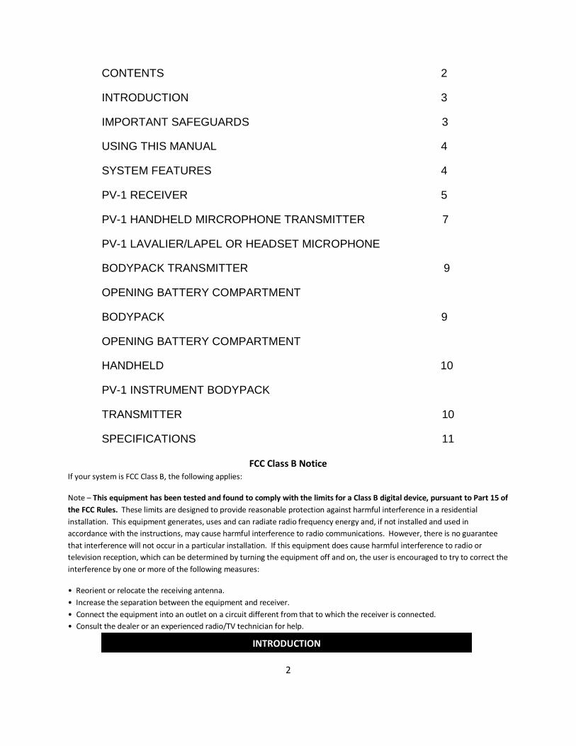
PV™1 VHF Wireless microphone system
2
CONTENTS 2
INTRODUCTION 3
IMPORTANT SAFEGUARDS 3
USING THIS MANUAL 4
SYSTEM FEATURES 4
PV-1 RECEIVER 5
PV-1 HANDHELD MIRCROPHONE TRANSMITTER 7
PV-1 LAVALIER/LAPEL OR HEADSET MICROPHONE
BODYPACK TRANSMITTER 9
OPENING BATTERY COMPARTMENT
BODYPACK 9
OPENING BATTERY COMPARTMENT
HANDHELD 10
PV-1 INSTRUMENT BODYPACK
TRANSMITTER 10
SPECIFICATIONS 11
FCC Class B Notice If your system is FCC Class B, the following applies:
Note – This equipment has been tested and found to comply with the limits for a Class B digital device, pursuant to Part 15 of the FCC Rules. These limits are designed to provide reasonable protection against harmful interference in a residential installation. This equipment generates, uses and can radiate radio frequency energy and, if not installed and used in accordance with the instructions, may cause harmful interference to radio communications. However, there is no guarantee that interference will not occur in a particular installation. If this equipment does cause harmful interference to radio or television reception, which can be determined by turning the equipment off and on, the user is encouraged to try to correct the interference by one or more of the following measures:
• Reorient or relocate the receiving antenna. • Increase the separation between the equipment and receiver. • Connect the equipment into an outlet on a circuit different from that to which the receiver is connected. • Consult the dealer or an experienced radio/TV technician for help.
INTRODUCTION
3
Thank you for purchasing a PEAVEY PV®-1 Diversity Wireless Microphone System. The PV-1 VHF wireless systems have user friendly features and are available in handheld, lavalier, headset and guitar models.
CAUTION!
1) DO NOT attempt to make internal adjustments to the system. Please refer all servicing to your authorized Peavey Service Center.
2) Turn the unit off if it is exposed to excessive moisture while in operation. Allow unit to dry thoroughly, then power back up. If unit fails to power up, then refer unit to your authorized Peavey Service Center.
WARNING! Risk of injury or death if used improperly
DURING INSTALLATION AND SET UP
To reduce the risk of shock DO NOT handle AC/DC adapter with wet hands.
To reduce the risks of fire or shock from damaged power cord always remove cord from outlet by grasping the adapter tightly while unplugging.
To reduce the risk of fire or shock from damaged power cord always turn unit off before moving it.
To reduce the risk of fire or shock DO NOT expose this equipment to moisture or dust.
To reduce the risk of fire or shock use only with specified voltage.
To reduce the risk of fire or shock DO NOT damage the power cord by placing it near a heat source or stacking heavy items on top of it.
To prevent damage to unit DO NOT place on surface that is unstable or that can tip over.
DURING OPERATION
To reduce the risk of fire or shock DO NOT remove the chassis cover. There are no user- serviceable parts inside. For all repairs refer unit to your authorized Peavey Service Center.
To reduce the risk of fire or shock DO NOT place water or metal items on top of unit.
To reduce the risk of fire or shock DO NOT allow metal, liquids or flammable items fall into unit.
To reduce the risk of fire or shock DO NOT touch AC outlet during thunderstorms.
IMPORTANT SAFEGUARDS
4
To prevent injury DO NOT place heavy items on top of unit.
Clear the dust out from the inside regularly. Accumulated dust can create a fire hazard as well as damage to the equipment.
Clear the dust out from plug and AC outlet. Again this accumulated dust can create a fire hazard.
Make sure the AC/DC adapter is plugged in entirely. No exposed metal.
When not in use for long periods of time, turn unit off and remove the AC adapter.
This booklet gives instructions for the operation of the PV-1 VHF wireless, including handheld, instrument, lavalier, headset and plug-in transmitter systems. Please read the instructions for your system completely before operating unit. This manual will first list the features of the PV-1 and then will take you step by step on how to operate your system. After reading the receiver instructions, turn to the section of the booklet that covers the type of transmitter used with your system. Each section will give you detailed operating instructions. Also included in this manual are system specifications and servicing information.
• Available on selected frequencies in the VHF band for long range performance • Proprietary compander circuitry for an industry-best 120dB Dynamic Range, and the clearest, most
natural sound available • Operating Range: Up to 250 feet typical (depending on site conditions)- 500+ feet line-of site • Noise-free transmitter ON-OFF operation
PV-1 RECEIVER
• Half-rack receiver design with retractable front panel dual antennas • Proprietary diversity digital processing circuitry to eliminate dropouts and maximize operating range • RF and AF 4-LED displays for monitoring incoming signal strength and audio level • Balanced XLR and unbalanced adjustable ¼” jack outputs • Mute (squelch) adjust control • Externally powered by AC/DC power adapter • Unique snap-out panel locking tabs for single receiver or dual receiver (side-by-side) optional rack
mounting kits available
USING THIS MANUAL
SYSTEM FEATURES
5
PV®-1 HANDHELD MIC TRANSMITTER
• Features the Peavey unidirectional neodymium dynamic cartridge for optimum true sound, maximum feedback rejection and minimal handling noise
• OFF/ON/STANDBY switch allows convenient audio muting with the transmitter “ON” • Low battery LED indicator flashes once for unit “ON”; lights steady for low battery alert
PV-1 BODYPACK TRANSMITTERS
• Choice of instrument headset or lavalier microphone bodypack transmitter • OFF/STANDBY/ON switch allows convenient audio muting with the transmitter “ON” • Low battery LED indicator flashes once for unit “ON’; lights steady for low battery alert • Locking 3.5mm mini-jack provides secure connection for removable microphone or instrument cable • Easily accessible input level adjust control for optimum sound
1. Powering the Receiver
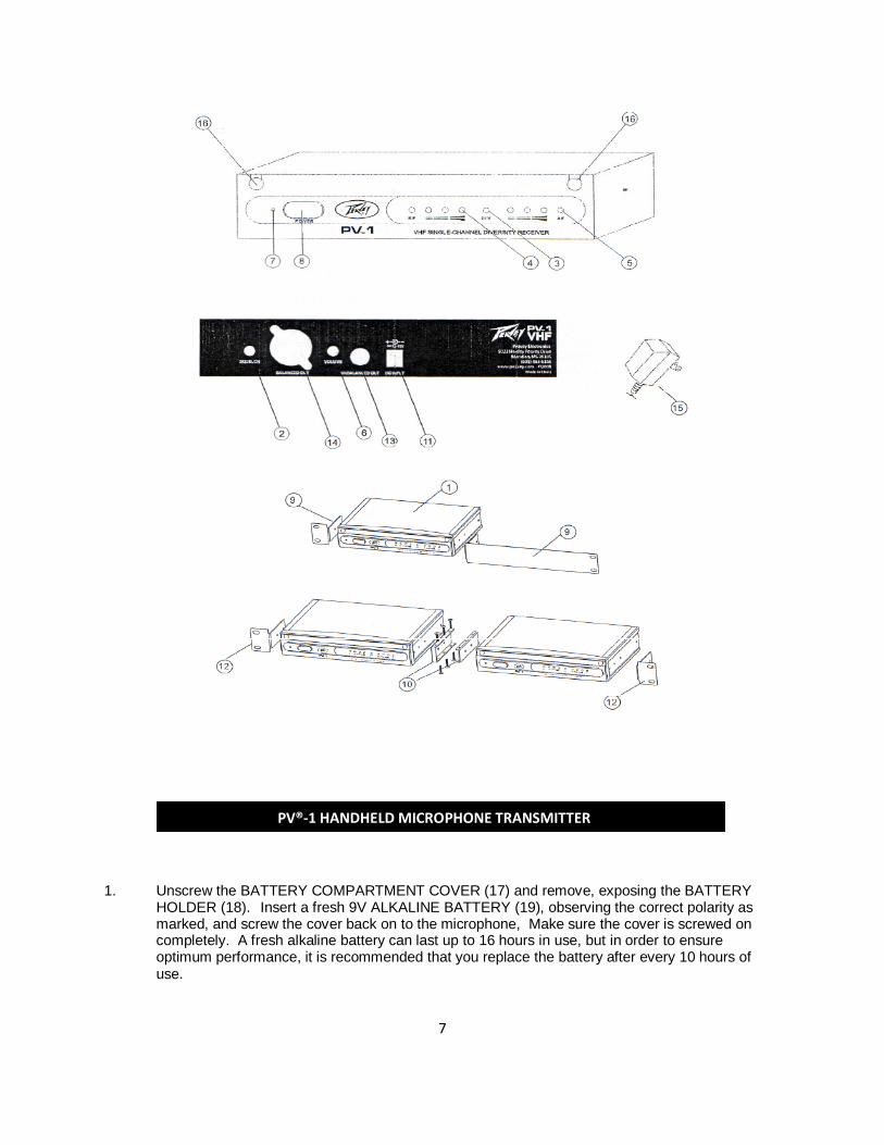
Plug the 12V AC/DC ADAPTER (15) provided into the DC INPUT JACK (11) on the back of the receiver. Then plug the power supply into an AC outlet. (Note: Any 12V DC source with 400mA capability can also be used.) Press the POWER SWITCH (8) to turn on the receiver. The POWER ON LED (7) will now light and the receiver is operational.
2. Antennas
The PV-1 receiver is supplied with TELESCOPIC ANTENNAS (16). These should be extended fully to obtain maximum range. Optimal antenna positions are 45 degrees from the receiver (at 90 degrees from each other). For maximum range, it is always best to maintain a line of sight (no obstructions) between the receiver antennas and the transmitter at all times whenever possible.
3. Squelch Adjustment
In normal operation, the Squelch CONTROL (2) should be set fully counterclockwise to the factory preset minimum RF level. However, in areas of high RF activity, the mute (or squelch, as it is sometimes called) may need to be adjusted to compensate for the adverse conditions in a particular location. If, with the transmitter off, the receiver’s A and/or B DIVERSITY LED INDICTORS (3) and/or one or more LEDs of the 4 LED RF LEVEL DISPLAY (4) flicker or stay on, the squelch control should be turned clockwise until the LEDs extinguish. When the squelch is properly adjusted, the A and/or B LEDs or the RF LEVEL LED displays will only light when the system transmitter is turned on. Turning the squelch control too far clockwise will reduce the range, but yield a quieter mute (squelch) function. During operation especially at ranges greater than 75 feet, one or the other of the A or B LEDs may extinguish briefly. This is normal. The unit’s diversity reception ensures that the received audio will not be interrupted. When both the A/B DIVERSITY LEDs and the 4 LED RF LEVEL display extinguish, the transmitter is out of range for that given location, and the user should move closer to the receiver to re-establish the radio link.
PV-1 RECEIVER
6
4. Connecting the Audio Output
The PV®-1 receiver provides both a fixed mic level BALANCED AUDIO OUTPIT XLR (14) and an adjustable line level UNBALANCED AUDIO OUTPUT ¼” JACK (13). The level from the UNBALANCED OUTPUT is controlled by the rear panel VOLUME CONTROL (6). (Note: As when making any connection, make sure the amplifier or mixing board volume is at the minimum level before plugging in the receiver to avoid possible sound system damage.)
Instrument Connection (using the PV-1 instrument transmitter)
Insert an audio cord with a ¼” mono phone plug in the UNBALANCED OUTPUT JACK (13) on the rear panel of the receiver. Plug the other end of the cord into an amplifier, effects, or mixing board. Adjust the VOLUME CONTROL (6) on the PV-1 receiver clockwise until the volume level is comfortable for your application. This setting is roughly equivalent to a direct instrument cord connection.
A. Microphone Connection (using the PV-1 transmitter with either a headset or lavalier microphone or the PV-1 handheld microphone transmitter)
For microphone use, either the BALANCED MIC AUDIO OUTPUT XLR (14) or the ¼” line level UNBALANCED OUTPUT (13) can be used. The XLR output is set at a non-adjustable microphone level, similar to hardwired mic levels. Plug an XLR connector into the XLR output jack on the rear of the unit and plug the other end into your amplifier or mixing board. (Note: Make sure mixing board is turned off and the volume is turned down when making connections.) For your convenience, the XLR output level is preset at the factory and is not adjustable with the receiver volume control. To use the ¼” UNBALANCED OUTPUT JACK (13), follow the instructions for the Instrument Connection (above), except start with the receiver volume at ½” MAX and adjust the volume control until the volume level is optima. If the volume control is set too high, you may overload your mixer or amp.
7
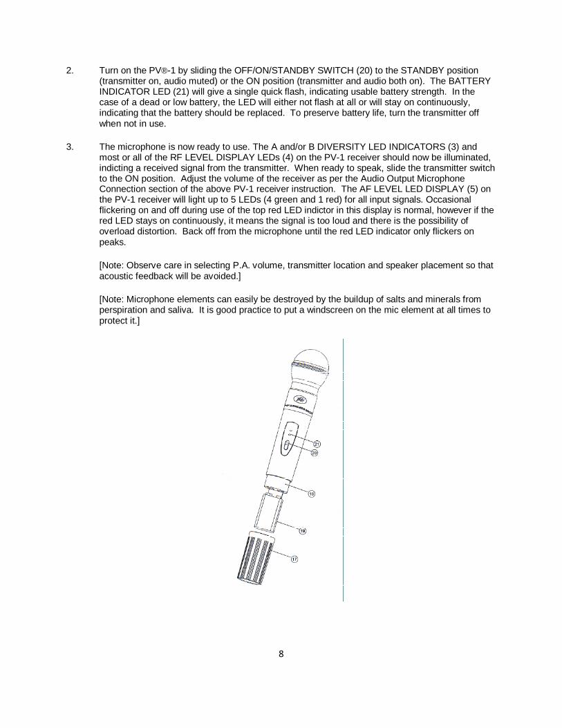
1. Unscrew the BATTERY COMPARTMENT COVER (17) and remove, exposing the BATTERY HOLDER (18). Insert a fresh 9V ALKALINE BATTERY (19), observing the correct polarity as marked, and screw the cover back on to the microphone, Make sure the cover is screwed on completely. A fresh alkaline battery can last up to 16 hours in use, but in order to ensure optimum performance, it is recommended that you replace the battery after every 10 hours of use.
PV®-1 HANDHELD MICROPHONE TRANSMITTER
8
2. Turn on the PV®-1 by sliding the OFF/ON/STANDBY SWITCH (20) to the STANDBY position (transmitter on, audio muted) or the ON position (transmitter and audio both on). The BATTERY INDICATOR LED (21) will give a single quick flash, indicating usable battery strength. In the case of a dead or low battery, the LED will either not flash at all or will stay on continuously, indicating that the battery should be replaced. To preserve battery life, turn the transmitter off when not in use.
3. The microphone is now ready to use. The A and/or B DIVERSITY LED INDICATORS (3) and most or all of the RF LEVEL DISPLAY LEDs (4) on the PV-1 receiver should now be illuminated, indicting a received signal from the transmitter. When ready to speak, slide the transmitter switch to the ON position. Adjust the volume of the receiver as per the Audio Output Microphone Connection section of the above PV-1 receiver instruction. The AF LEVEL LED DISPLAY (5) on the PV-1 receiver will light up to 5 LEDs (4 green and 1 red) for all input signals. Occasional flickering on and off during use of the top red LED indictor in this display is normal, however if the red LED stays on continuously, it means the signal is too loud and there is the possibility of overload distortion. Back off from the microphone until the red LED indicator only flickers on peaks.
[Note: Observe care in selecting P.A. volume, transmitter location and speaker placement so that acoustic feedback will be avoided.]
[Note: Microphone elements can easily be destroyed by the buildup of salts and minerals from perspiration and saliva. It is good practice to put a windscreen on the mic element at all times to protect it.]
9
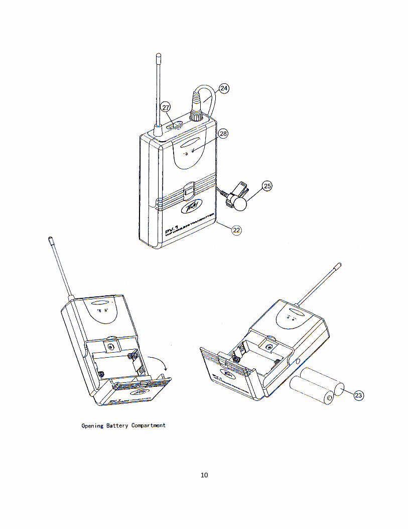
1. Snap open the BATTERY COMPARTMENT and insert 2 fresh AA BATTERIES (23), observing the correct polarity. Close the compartment.
2. The PV-1 is provided with a 3.5 mm LOCKING JACK (24) for connecting the microphone, plug in either the LAVALIER/LAPEL (25) OR THE HEADSET MICROPHONE as supplied. To secure the connection, insert locking mini-XLR into the jack. To unplug, reverse the process.
Slip the transmitter into a pocket or clip on to your clothes. To use the lavalier mic, attach it at chest level or higher. Do not place lavalier mic too close to the mouth – a distance of about six inches is recommended. To use the headset mic, place it on your head and adjust the mic boom so that the mic is about one inch to the side of the front of the mouth. (Note: The lavalier or headset mic wire is also the transmitter antenna, and rolling up or shortening the wire may reduce the effective operating range. Extend the wire fully during use, and keep it as straight as possible.)
3. Turn on the PV-1 by sliding the OFF/STANDBY/ON SWITCH (27) to the STANDBY position (transmitter on, audio muted) or the ON position (transmitter and audio both on). The BATTERY INDICATOR LED (28) will give a single quick flash, indicting usable battery strength. In the case of a dead or low battery, the LED either will not illuminate at all or will stay on continuously, indicating that the batteries should be replaced.
4. The microphone is now ready to use. The A and/or B DIVERSITY LED INDICATORS (3) and most or all of the RF DISPLAY LEDs (4) on the PV-1 receiver should now be illuminated, indicating a received signal from the transmitter. When ready to speak, slide the transmitter switch to the ON position and adjust the volume of the receiver as per the Audio Output Microphone Connection section of the above PV-1 receiver instructions. The AF LEVEL LED DISPLAY (5) on the PV-1 receiver will light up to 4 LEDs (3 green and 1 red) for all input signals. Occasional flickering on and off during use of the top red LED indicator in this display is normal, however if the red LED stays on continuously, it means the signal is too loud and there is the possibility of overload distortion. Re-position the microphone farther from the source until the red LED indicator flickers only on the loudest inputs.
[Note: Observe care in selecting P.A. volume, transmitter location and speaker placement so that acoustic feedback will be avoided. Please also observe the pickup patterns of the microphone selected: omnidirectional mics pick up sound equally from all directions and are prone to feedback if not used carefully. Unidirectional mics are more resistant to feedback, but pick up sound sources best that are directly in front of the mic. Also, mics that are farther from the sound source, such as lavaliers, require more acoustic gain and thus are also more prone to feedback than close-source mics such as handheld or headset mics that are used close to the mouth.]
[Note: Microphone elements can easily be destroyed by the buildup of salts and mineral from perspiration and saliva. It is good practice to put a windscreen on the mic element at all times to protect it.]
PV®-1 LAVALIER/LAPEL OR HEADSET MICROPHONE BODYPACK TRANSMITTER
10
11
• Frequency Response 40-20,000Hz, +/- 3dB • Dynamic Range 120dB • Total Harmonic Distortion <0.3% • Frequency Stability +/- 0.005%, Crystal controlled • Modulation FM (F3E), +/-20KHz max. • Operating Range Up to 250 ft. typical (depending on site conditions); up to 500+ feet
optimum line of sight
TRANSMITTERS
Audio Inputs • PV®-1 Peavey neodymium dynamic cartridge • PV-1 3.5mm mono locking jack for connecting to omni or unidirectional lavalier mic or
unidirectional headset mic, with phantom power (PV-1); or connecting to instrument cable (PV-1) Controls
• PV-1 OFF/ON switch • PV-1 OFF/ON switch, input level adjust • LED Indicator Unit “ON” (single flash) • Low Battery Alert (Steady) • RF Power Out 50mW (max. allowed by FCC) • Harmonic & Spurious Emissions> - • Battery 9V Alkaline Handheld – 2) AA Body Pack • Battery Life up to 15 hours • Dimensions 4.2” x 2.5” .88”
(10.7 x 6.4 x 2.2 cm) 9.5” x 1.37” (24.1 x 3.48 cm)
• Weight 3 oz (84g) – 7.5 oz (210g)
RECEIVER
• Reception Mode – Diversity • Controls – Power ON/OFF, volume control, mute control • Connectors – Balanced XLR and unbalanced adjustable ¼” audio jacks, 2.1mm barrel-
type DC input jack • LED Indicators – Power ON, 4 LED RF & AF level displays, A/B Diversity • Power Requirements – 12V @ 400mA, nominal, AC/DC adapter supplied
Features and specifications subject to change without notice.
SPECIFICATIONS

12