Embed Size (px)
Citation preview
PV Series
PVN Vertical Nozzled
PVD Vertical Ducted
Gas Fired Balanced FlueCabinet Heaters
Introduction
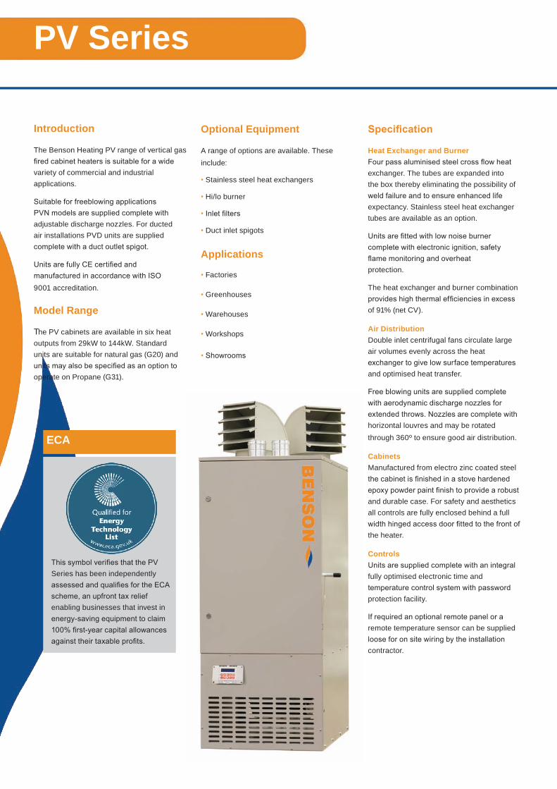
The Benson Heating PV range of vertical gasfired cabinet heaters is suitable for a widevariety of commercial and industrialapplications.
Suitable for freeblowing applicationsPVN models are supplied complete withadjustable discharge nozzles. For ductedair installations PVD units are suppliedcomplete with a duct outlet spigot.
Units are fully CE certified andmanufactured in accordance with ISO9001 accreditation.
Model Range
The PV cabinets are available in six heat outputs from 29kW to 144kW. Standard units are suitable for natural gas (G20) and units may also be specified as an option to operate on Propane (G31).
Optional Equipment
A range of options are available. These include:
• Stainless steel heat exchangers
• Hi/lo burner
• Inlet filters
• Duct inlet spigots
Applications
• Factories
• Greenhouses
• Warehouses
• Workshops
• Showrooms
Specification
Heat Exchanger and BurnerFour pass aluminised steel cross flow heat exchanger. The tubes are expanded intothe box thereby eliminating the possibility of weld failure and to ensure enhanced lifeexpectancy. Stainless steel heat exchanger tubes are available as an option.
Units are fitted with low noise burnercomplete with electronic ignition, safetyflame monitoring and overheatprotection.
The heat exchanger and burner combinationprovides high thermal efficiencies in excessof 91% (net CV).
Air DistributionDouble inlet centrifugal fans circulate largeair volumes evenly across the heatexchanger to give low surface temperaturesand optimised heat transfer.
Free blowing units are supplied completewith aerodynamic discharge nozzles forextended throws. Nozzles are complete withhorizontal louvres and may be rotatedthrough 360º to ensure good air distribution.
CabinetsManufactured from electro zinc coated steelthe cabinet is finished in a stove hardenedepoxy powder paint finish to provide a robustand durable case. For safety and aestheticsall controls are fully enclosed behind a fullwidth hinged access door fitted to the front ofthe heater.
ControlsUnits are supplied complete with an integralfully optimised electronic time andtemperature control system with passwordprotection facility.
If required an optional remote panel or aremote temperature sensor can be suppliedloose for on site wiring by the installationcontractor.
PV Series
This symbol verifies that the PV Series has been independently assessed and qualifies for the ECA scheme, an upfront tax relief enabling businesses that invest in energy-saving equipment to claim 100% first-year capital allowances against their taxable profits.
ECA
Installation
Units should be installed on a flat non-combustible base capable of supportingthe unit weight and ensuring that therecommended clearances for correctairflows and service access are observed.
Consideration must also be given to theroute and length of the flue, and ifrequired the ducted combustion air inlet.
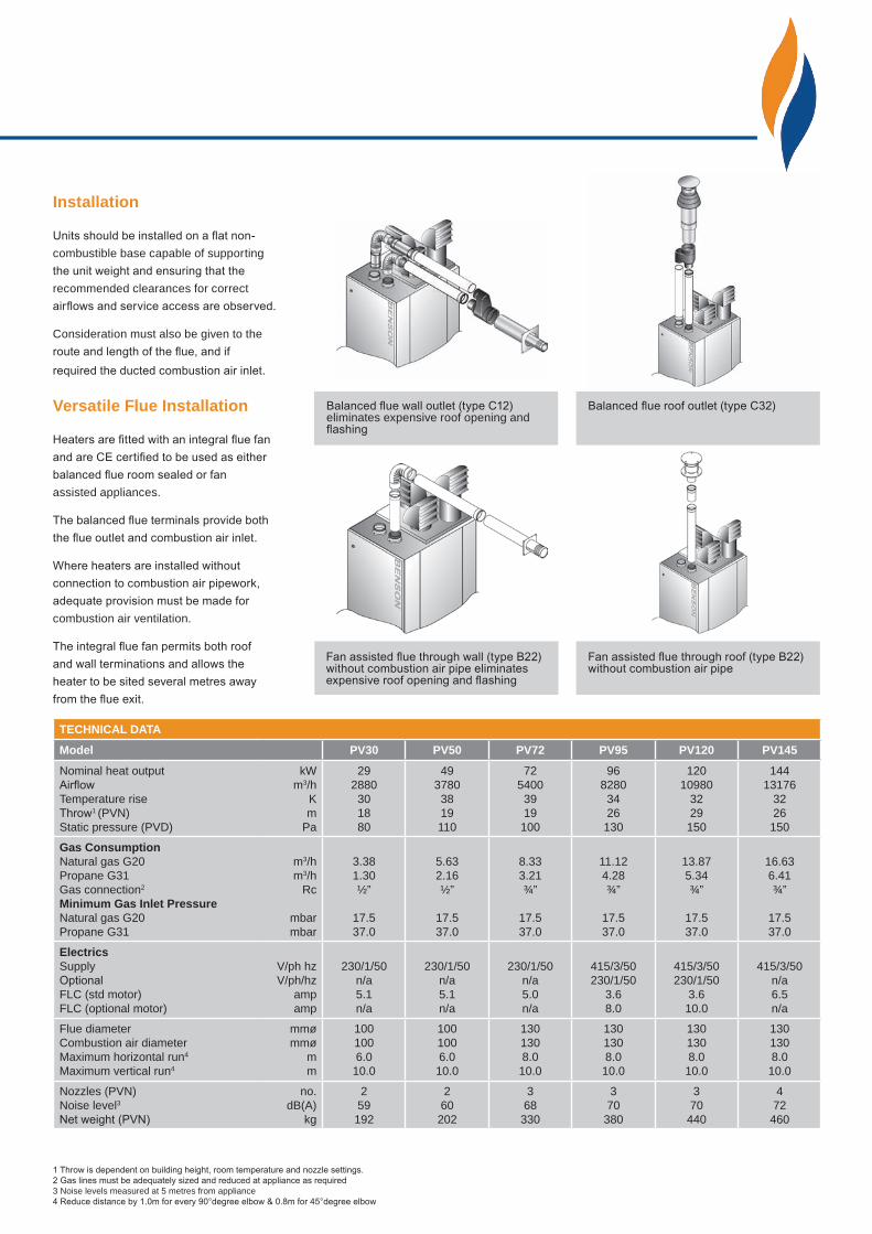
Versatile Flue Installation
Heaters are fitted with an integral flue fanand are CE certified to be used as eitherbalanced flue room sealed or fanassisted appliances.
The balanced flue terminals provide boththe flue outlet and combustion air inlet.
Where heaters are installed withoutconnection to combustion air pipework,adequate provision must be made forcombustion air ventilation.
The integral flue fan permits both roofand wall terminations and allows theheater to be sited several metres awayfrom the flue exit.
TECHNICAL DATA
Model PV30 PV50 PV72 PV95 PV120 PV145
Nominal heat outputAirflow Temperature rise Throw1 (PVN) Static pressure (PVD)
kWm3/h
K m
Pa
292880301880
4937803819110
7254003919100
9682803426130
12010980
3229150
14413176
3226150
Gas ConsumptionNatural gas G20Propane G31 Gas connection2
Minimum Gas Inlet PressureNatural gas G20Propane G31
m3/hm3/h
Rc
mbarmbar
3.381.30½”
17.5 37.0
5.632.16½”
17.537.0
8.333.21¾”
17.537.0
11.124.28¾”
17.537.0
13.875.34¾”
17.537.0
16.636.41¾”
17.537.0
ElectricsSupply OptionalFLC (std motor)FLC (optional motor)
V/ph hz V/ph/hz
amp amp
230/1/50n/a5.1n/a
230/1/50n/a5.1n/a
230/1/50n/a5.0n/a
415/3/50230/1/50
3.68.0
415/3/50230/1/50
3.610.0
415/3/50n/a6.5n/a
Flue diameter Combustion air diameter Maximum horizontal run4
Maximum vertical run4
mmø mmø
m m
1001006.010.0
1001006.010.0
1301308.010.0
1301308.010.0
1301308.010.0
1301308.010.0
Nozzles (PVN) Noise level3 Net weight (PVN)
no. dB(A)
kg
259192
260202
368330
370380
370440
472460
1 Throw is dependent on building height, room temperature and nozzle settings.2 Gas lines must be adequately sized and reduced at appliance as required3 Noise levels measured at 5 metres from appliance 4 Reduce distance by 1.0m for every 90°degree elbow & 0.8m for 45°degree elbow
Fan assisted flue through wall (type B22) without combustion air pipe eliminates expensive roof opening and flashing
Fan assisted flue through roof (type B22) without combustion air pipe
Balanced flue roof outlet (type C32) Balanced flue wall outlet (type C12) eliminates expensive roof opening and flashing
F
A
F
A
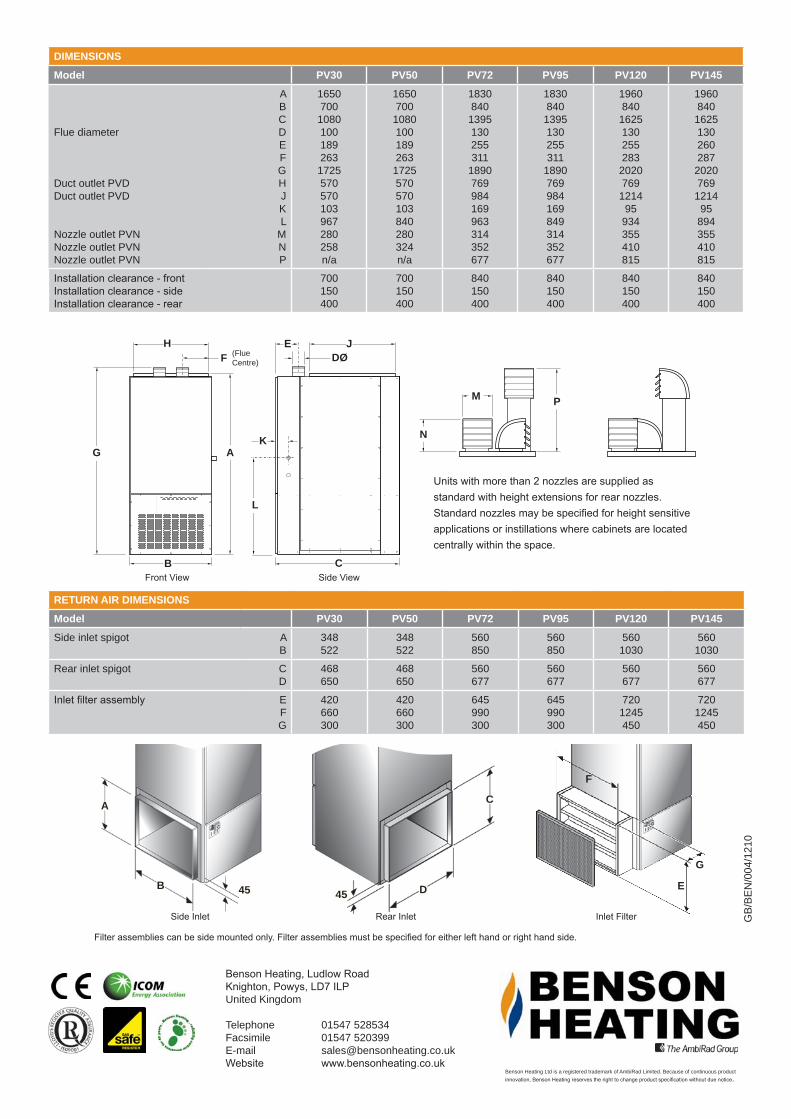
Units with more than 2 nozzles are supplied as standard with height extensions for rear nozzles. Standard nozzles may be specified for height sensitive applications or instillations where cabinets are located centrally within the space.
Page 6
DIMENSIONS
Power Vented Vertical Cabinet HeaterNatural Gas and Lpg Propane - PVN PVD
Note -Side inlet spigots require to be specified either left hand or right hand
Model 100 170 250 330 410 490A All mm 1650 1650 1990 1990 2140 2140B All mm 700 700 840 840 840 840C All mm 1050 1050 1395 1395 1750 1750D All mm ø 100 100 130 130 130 130E All mm 189 189 255 255 255 260F All mm 263 263 311 311 283 287G All mm 1725 1725 2050 2050 2200 2200H All mm 570 570 769 769 769 769J All mm 570 570 984 984 1339 1339K All mm 103 103 169 169 95 95L All mm 967 840 1091 977 1113 1033M All mm 280 280 280 280 314 314N All mm 258 324 324 324 352 352P All mm n/a n/a 609 609 677 677
Return Air Details
PM
N
45
C
D45
A
B
Side Return Air Inlet
Model 100 170 250 330 410 490
Side Inlet Spigot All A mm 348 348 427 427 640 640B mm 522 522 702 702 1155 1155
Rear Inlet Spigot All C mm 468 468 640 640 640 640D mm 650 650 677 677 677 677
RETURN AIR DIMENSIONS
Model PV30 PV50 PV72 PV95 PV120 PV145
Side inlet spigot AB
348522
348522
560850
560850
5601030
5601030
Rear inlet spigot CD
468650
468650
560677
560677
560677
560677
Inlet filter assembly EFG
420660300
420660300
645990300
645990300
7201245450
7201245450
Front View Side View
Benson Heating, Ludlow RoadKnighton, Powys, LD7 ILPUnited Kingdom
Telephone 01547 528534Facsimile 01547 520399E-mail [email protected] www.bensonheating.co.uk
Side Inlet Rear Inlet Inlet Filter
Filter assemblies can be side mounted only. Filter assemblies must be specified for either left hand or right hand side.
F
A
N
M P
JDØ
C
H
L
E
A
B
KG
F (Flue Centre)
A
B 45 45 D
C
F
G
E
DIMENSIONS
Model PV30 PV50 PV72 PV95 PV120 PV145
Flue diameter Duct outlet PVD Duct outlet PVD Nozzle outlet PVN Nozzle outlet PVNNozzle outlet PVN
ABCDEFGHJKL
MNP
1650 700 1080 100 189 263 1725 570 570 103 967 280 258n/a
1650 700 1080 100 189 263 1725 570 570 103 840 280 324n/a
1830 840 1395 130 255 311
1890 769 984 169 963 314 352 677
1830 840 1395 130 255 311
1890 769 984 169 849 314 352 677
1960 840 1625 130 255 283 2020 769 1214
95 934 355 410 815
1960 840 1625 130 260 287 2020 769 1214
95 894 355 410 815
Installation clearance - front Installation clearance - side Installation clearance - rear
700150400
700150400
840150400
840150400
840150400
840150400
Benson Heating Ltd is a registered trademark of AmbiRad Limited. Because of continuous productinnovation, Benson Heating reserves the right to change product specification without due notice.
GB/
BEN
/004
/121
0