Embed Size (px)
Citation preview
Page 1 of 12
PV Newsletter – March 2013: Components of Shell and Tube Heat Exchangers
March 15, 2013 www.codesignengg.com
PV NewsletterPV NewsletterPV NewsletterPV Newsletter Monthly Publication from CoDesign Engineering Skills Academy
Components of Shell-and-Tube Heat Exchangers
The principal components of shell-and-tube heat exchangers are:
� Tubes
� Tubesheet
� Shell and Shell-Side Nozzles
� Tube-Side Channel and Nozzles
� Baffles
� Tie-rods
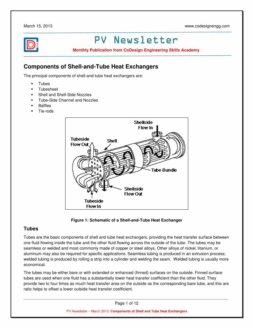
Figure 1: Schematic of a Shell-and-Tube Heat Exchanger
Tubes
Tubes are the basic components of shell and tube heat exchangers, providing the heat transfer surface between
one fluid flowing inside the tube and the other fluid flowing across the outside of the tube. The tubes may be
seamless or welded and most commonly made of copper or steel alloys. Other alloys of nickel, titanium, or
aluminum may also be required for specific applications. Seamless tubing is produced in an extrusion process;
welded tubing is produced by rolling a strip into a cylinder and welding the seam. Welded tubing is usually more
economical.
The tubes may be either bare or with extended or enhanced (finned) surfaces on the outside. Finned surface
tubes are used when one fluid has a substantially lower heat transfer coefficient than the other fluid. They
provide two to four times as much heat transfer area on the outside as the corresponding bare tube, and this are
ratio helps to offset a lower outside heat transfer coefficient.

Page 2 of 12
PV Newsletter – March 2013: Components of Shell and Tube Heat Exchangers
Normal tube diameters are 5/8”, ¾” and 1”. Tubes of smaller diameter can be used but they are more difficult to
clean mechanically. Tubes of larger diameter are sometimes used either to facilitate mechanical cleaning or to
achieve lower pressure drop. The normal tube wall thickness ranges from 12 to 16 BWG (from 0.109 inches to
0.065 inches thick). Tubes with thinner walls (18 to 20 BWG) are used when the tubing material is relatively
expensive such as titanium.
Tubesheets
The tubes are held in place by being inserted into holes in the tubesheets and then either expanded into grooves
cut into the holes or welded to the tubesheet where the tube protrudes from the surface. This prevents the fluid
on the shell side from mixing with the fluid on the tube side. The tubesheet is usually a single round plate of
metal that has been suitably drilled and grooved to take the tubes (in desired pattern - square or triangular), the
gaskets, the spacer rods, and the bolt circle where it is fastened to the shell.
The distance between the centers of the tube hole is called the tube pitch; normally the tube pitch is 1.25 times
the outside diameter of the tubes. Other tube pitches are frequently used to reduce the shell side pressure drop
and to control the velocity of the shell side fluid as it flows across the tube bundle. Triangular pitch is most often
applied because of higher heat transfer and compactness it provides. Square pitch facilitates mechanical
cleaning of the outside of the tubes.
Two tubesheets are required except for U-tube bundles. A rolled joint is the common term for a tube-to-tube
sheet joint resulting from a mechanical expansion of the tube against the tubesheet. This joint is most often
achieved using roller expanders; hence the term rolled joint. Less frequently, tubes are expanded by hydraulic
processes to affect a mechanical bond. Tubes can also be welded to the front or inboard face of the
tubesheet. Strength welding designates that the mechanical strength of the joint is provided primarily by the
welding procedure and the tubes are only lightly expanded against the tubesheet to eliminate the crevice that
would otherwise exist. Seal welding designate that the mechanical strength of the joint is provided primarily by
the tube expansion with the tubes welded to the tubesheet for better leak protection. The cost of seal-welded
joints is commonly justified by increased reliability, reduced maintenance costs, and fewer process leaks. Seal-
welded joints are required when clad tubesheets are used, when tubes with wall thickness less than 16 BWG
(0.065 inch) are used, and for some metals that cannot be adequately expanded to achieve an acceptable
mechanical bond (titanium and Alloy 2205 for instance).
Where mixing between the two fluids must be avoided, a double tubesheet such as is shown in Figure 2 may be
provided. The space between tubesheets is open to the atmosphere so any leakage of either fluids should be
quickly detected.
Figure 2: Double Tubesheet
The tubesheet, in addition to its mechanical requirements, must withstand corrosive attack by both fluids in heat
exchanger and must be electrochemically compatible with the tube and all tube-side material.
Page 3 of 12
PV Newsletter – March 2013: Components of Shell and Tube Heat Exchangers
Shell and Shell-Side Nozzles
The shell is simply the container for the shell-side fluid, and the nozzles are the inlet and exit ports. The shell
normally has a circular cross section and is commonly made by rolling a metal plate of appropriate dimensions
into a cylinder and welding the longitudinal joint. Small diameter shells can be made by cutting the pipe of the
desired diameter to the correct length. The roundness of the shell is important in fixing the maximum diameter of
the baffles that can be inserted, and therefore the effect of shell-to-baffle leakage.
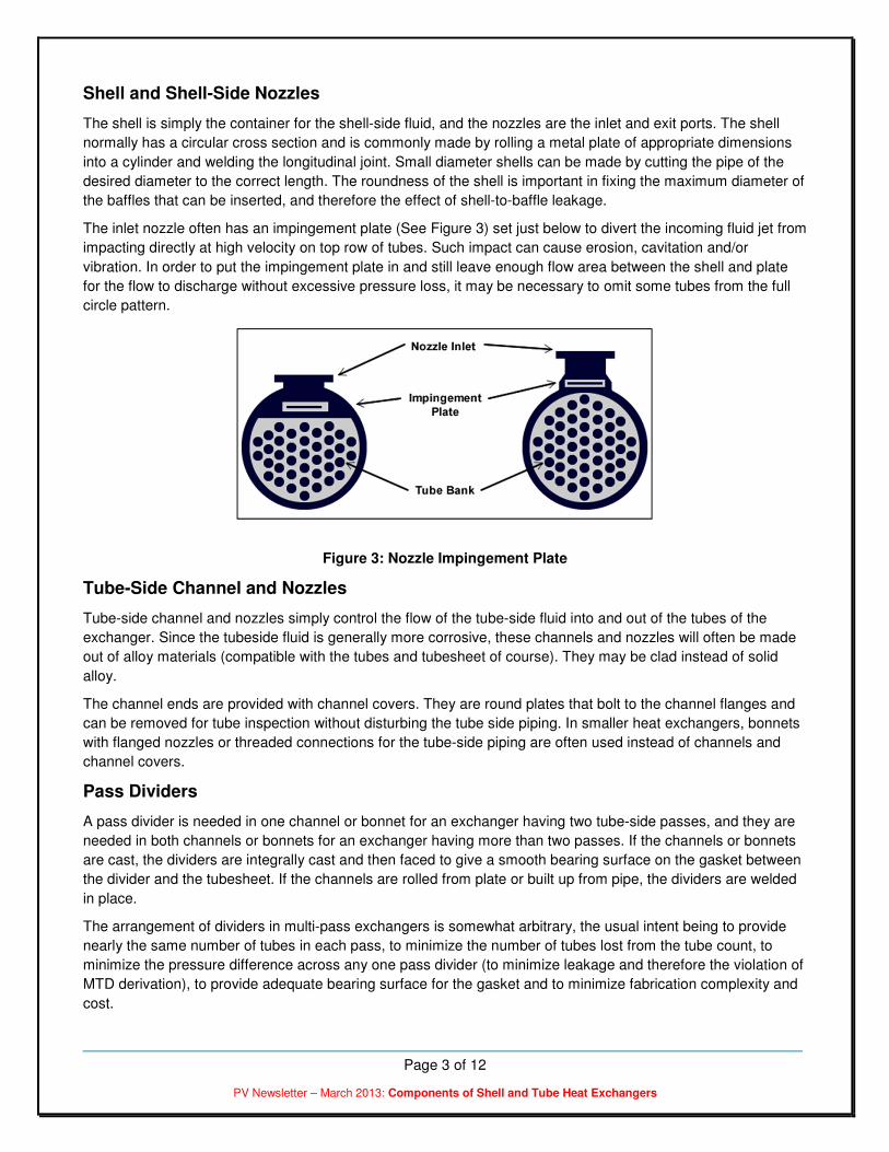
The inlet nozzle often has an impingement plate (See Figure 3) set just below to divert the incoming fluid jet from
impacting directly at high velocity on top row of tubes. Such impact can cause erosion, cavitation and/or
vibration. In order to put the impingement plate in and still leave enough flow area between the shell and plate
for the flow to discharge without excessive pressure loss, it may be necessary to omit some tubes from the full
circle pattern.
Figure 3: Nozzle Impingement Plate
Tube-Side Channel and Nozzles
Tube-side channel and nozzles simply control the flow of the tube-side fluid into and out of the tubes of the
exchanger. Since the tubeside fluid is generally more corrosive, these channels and nozzles will often be made
out of alloy materials (compatible with the tubes and tubesheet of course). They may be clad instead of solid
alloy.
The channel ends are provided with channel covers. They are round plates that bolt to the channel flanges and
can be removed for tube inspection without disturbing the tube side piping. In smaller heat exchangers, bonnets
with flanged nozzles or threaded connections for the tube-side piping are often used instead of channels and
channel covers.
Pass Dividers
A pass divider is needed in one channel or bonnet for an exchanger having two tube-side passes, and they are
needed in both channels or bonnets for an exchanger having more than two passes. If the channels or bonnets
are cast, the dividers are integrally cast and then faced to give a smooth bearing surface on the gasket between
the divider and the tubesheet. If the channels are rolled from plate or built up from pipe, the dividers are welded
in place.
The arrangement of dividers in multi-pass exchangers is somewhat arbitrary, the usual intent being to provide
nearly the same number of tubes in each pass, to minimize the number of tubes lost from the tube count, to
minimize the pressure difference across any one pass divider (to minimize leakage and therefore the violation of
MTD derivation), to provide adequate bearing surface for the gasket and to minimize fabrication complexity and
cost.

Page 4 of 12
PV Newsletter – March 2013: Components of Shell and Tube Heat Exchangers
Baffles
Baffles (See Figure 4) serve three functions:
1) They support the tubes in proper position during assembly and operation and prevent vibration of the tubes
caused by flow-induced eddies
2) They guide the shell-side flow back and forth across the tube field, increasing the velocity and heat transfer
coefficient
3) They maintain the tube spacing
Figure 4: Segmental Baffles
A segment, called the baffle cut, is cut away to permit the fluid to flow parallel to the tube axis as it flows from
one baffle space to another. Segmental cuts with the height of the segment approximately 25 percent of the
shell diameter are normally the optimum. Baffle cuts larger or smaller than the optimum typically result in poorly
distributed shell side flow with large eddies, dead zones behind the baffles and pressure drops higher than
expected.
The spacing between segmental baffles is called the baffle pitch. The baffle pitch and the baffle cut determine
the cross flow velocity and hence the rate of heat transfer and the pressure drop. The baffle pitch and baffle cut
are selected during the heat exchanger design to yield the highest fluid velocity and heat transfer rate while
respecting the allowable pressure drop. The baffle spacing should be correspondingly chosen to make the free
flow areas through the “window” (the area between the baffle edge and shell) and across the tube bank roughly
equal.
The orientation of the baffle cut is important for heat exchanger installed horizontally. When the shell side heat
transfer is sensible heating or cooling with no phase change, the baffle cut should be horizontal. This causes
the fluid to follow an up-and-down path and prevents stratification with warmer fluid at the top of the shell and
cooler fluid at the bottom of the shell. For shell side condensation, the baffle cut for segmental baffles is vertical
to allow the condensate to flow towards the outlet without significant liquid holdup by the baffle. For shell side
boiling, the baffle cut may be either vertical or horizontal depending on the service.
For many high velocity gas flows, the single segmental baffle configuration results in an undesirably high shell
side pressure drop. One way to retain the structural advantages of the segmental baffle and reduce the pressure
drop (and, regrettably, to some extent, the heat transfer coefficient too) is to use the double segmental baffle as
shown in Figure 5. Exact comparison must be made on a case-to-case basis, but the rough effect is to halve the
local velocity and therefore reduce the pressure drop by a factor of 4 from a comparable size single segmental
unit.
For sufficiently large units, it is possible to go to triple segmental arrangements and ultimately to strip and rod
baffles, the important point being always to insure that every tube is positively constrained at periodic distances
to prevent sagging and vibration.

Page 5 of 12
PV Newsletter – March 2013: Components of Shell and Tube Heat Exchangers
Other types of baffles are sometimes used such as: double segmental, triple segmental, helical baffle, EM baffle
and ROD baffle. Most of these types of baffles are designed to provide fluid flow paths other than cross
flow. These baffle types are typically used for unusual design conditions. Longitudinal baffles are sometimes
provided to divide the shell creating multiple passes on the shell side. This type of heat exchangers is
sometimes useful in heat recovery applications when several shell side passes allow the fluids to achieve a
severe temperature cross.
Figure 5: Double and Triple Segmental Baffles
Tie Rods
Tie rods and spacers are used for two reasons:
1) Hold the baffle assembly together; and
2) Maintain the selected baffle spacing.
The tie rods are secured at one end to the tubesheet and at the other end to the last baffle (See Figure 6). They
hold the baffle assembly together. The spacers are placed over the tie rods between each baffle to maintain the
selected baffle pitch. The minimum number of tie rod and spacers depends on the diameter of the shell and the
size of the tie rod and spacers.
Figure 6: Tie Rods
Page 6 of 12
PV Newsletter – March 2013: Components of Shell and Tube Heat Exchangers
Sources:Sources:Sources:Sources:
1. Wolverine Heat Transfer Data Book
2. HEI, “Standards for Closed Feedwater Heaters”, 8th Ed., The Heat Exchange Institute, Cleveland, Ohio
*** E N D O F T H E A R T I C L E ***
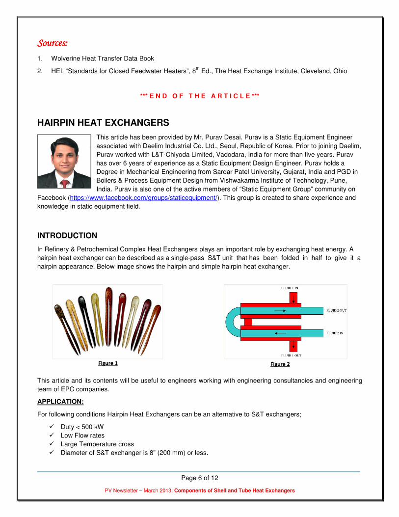
HAIRPIN HEAT EXCHANGERS
This article has been provided by Mr. Purav Desai. Purav is a Static Equipment Engineer
associated with Daelim Industrial Co. Ltd., Seoul, Republic of Korea. Prior to joining Daelim,
Purav worked with L&T-Chiyoda Limited, Vadodara, India for more than five years. Purav
has over 6 years of experience as a Static Equipment Design Engineer. Purav holds a
Degree in Mechanical Engineering from Sardar Patel University, Gujarat, India and PGD in
Boilers & Process Equipment Design from Vishwakarma Institute of Technology, Pune,
India. Purav is also one of the active members of “Static Equipment Group” community on
Facebook (https://www.facebook.com/groups/staticequipment/). This group is created to share experience and
knowledge in static equipment field.
INTRODUCTION
In Refinery & Petrochemical Complex Heat Exchangers plays an important role by exchanging heat energy. A
hairpin heat exchanger can be described as a single-pass S&T unit that has been folded in half to give it a
hairpin appearance. Below image shows the hairpin and simple hairpin heat exchanger.
This article and its contents will be useful to engineers working with engineering consultancies and engineering
team of EPC companies.
APPLICATION:
For following conditions Hairpin Heat Exchangers can be an alternative to S&T exchangers;
� Duty < 500 kW
� Low Flow rates
� Large Temperature cross
� Diameter of S&T exchanger is 8" (200 mm) or less.
Figure 1 Figure 2

Page 7 of 12
PV Newsletter – March 2013: Components of Shell and Tube Heat Exchangers
Conventional TEMA type S&T exchanger becomes uneconomical for above conditions because a large number
of small diameter shells in series are required to provide adequate velocities and near counter-current flow.
CONSTRUCTION:
It is classified based on construction as follows;
a) Double Pipe Heat Exchanger:
The basic double-pipe construction consists of a single pipe or tube, placed concentrically inside a larger
pipe or tube (Outer shell). Double pipe exchangers can have multiple configurations. Some typical
configurations are shown below in Figure 3 & Figure 4.
Configuration shown in figure 3 utilizes a front end closure at tube side inlet outlet nozzles, with
independent tube side and shell-side gasketing that prevent inter stream leakage. The closure
arrangement is also provided with external split ring that locks the tube element to the shell. At rear end
two inner tubes are joined together by a welded on U-bend, while the two outer shells are joined
together by a dished head and a flanged joint. The depth of dished head is sized to allow free axial
thermal movement of inner tubes & bend within the shell. This type of configuration is costly and may
need a special vendor.
Configuration shown in figure 4 is the simplest & cheapest construction which uses pipes, nozzles,
flange, standard 90º bend, gaskets and bolting. The disadvantage here is it does not utilize the bend
portion in heat transfer. So for the same heat duty requirement, it may need more no of shells.
b) Multitube Heat Exchanger:
Multitube heat exchanger contains bundle of U-tubes instead of a single inner tube as double pipe. Each
leg of the U-bundle has its own tubesheet and design permits free thermal movement of the bundle and
its withdrawal from the shell. The front end and rear end construction of multitube heat exchanger is
Figure 3
Figure 4
Page 8 of 12
PV Newsletter – March 2013: Components of Shell and Tube Heat Exchangers
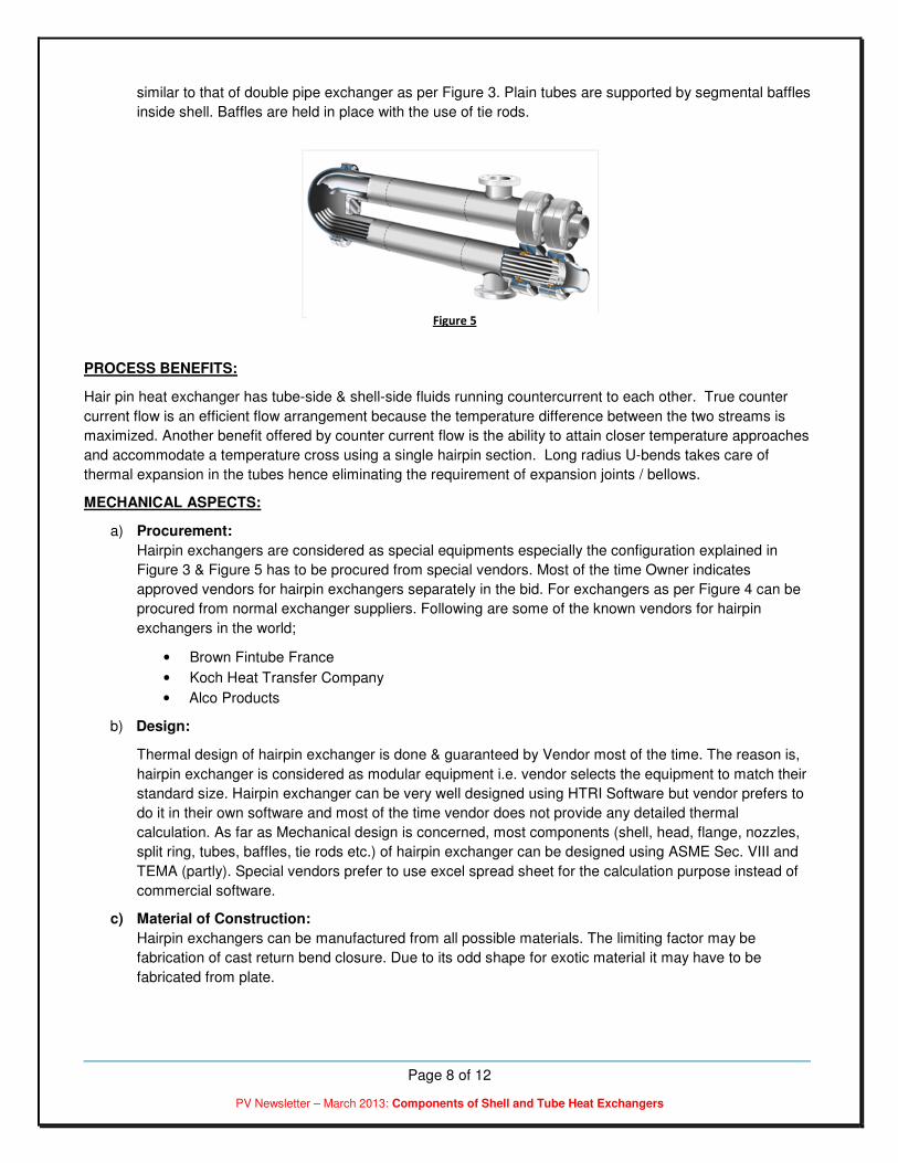
similar to that of double pipe exchanger as per Figure 3. Plain tubes are supported by segmental baffles
inside shell. Baffles are held in place with the use of tie rods.
PROCESS BENEFITS:
Hair pin heat exchanger has tube-side & shell-side fluids running countercurrent to each other. True counter
current flow is an efficient flow arrangement because the temperature difference between the two streams is
maximized. Another benefit offered by counter current flow is the ability to attain closer temperature approaches
and accommodate a temperature cross using a single hairpin section. Long radius U-bends takes care of
thermal expansion in the tubes hence eliminating the requirement of expansion joints / bellows.
MECHANICAL ASPECTS:
a) Procurement:
Hairpin exchangers are considered as special equipments especially the configuration explained in
Figure 3 & Figure 5 has to be procured from special vendors. Most of the time Owner indicates
approved vendors for hairpin exchangers separately in the bid. For exchangers as per Figure 4 can be
procured from normal exchanger suppliers. Following are some of the known vendors for hairpin
exchangers in the world;
• Brown Fintube France
• Koch Heat Transfer Company
• Alco Products
b) Design:
Thermal design of hairpin exchanger is done & guaranteed by Vendor most of the time. The reason is,
hairpin exchanger is considered as modular equipment i.e. vendor selects the equipment to match their
standard size. Hairpin exchanger can be very well designed using HTRI Software but vendor prefers to
do it in their own software and most of the time vendor does not provide any detailed thermal
calculation. As far as Mechanical design is concerned, most components (shell, head, flange, nozzles,
split ring, tubes, baffles, tie rods etc.) of hairpin exchanger can be designed using ASME Sec. VIII and
TEMA (partly). Special vendors prefer to use excel spread sheet for the calculation purpose instead of
commercial software.
c) Material of Construction:
Hairpin exchangers can be manufactured from all possible materials. The limiting factor may be
fabrication of cast return bend closure. Due to its odd shape for exotic material it may have to be
fabricated from plate.
Figure 5

Page 9 of 12
PV Newsletter – March 2013: Components of Shell and Tube Heat Exchangers
d) Range:
Hairpin exchangers are available in nominal shell size of 2" to 30". Hairpin Exchangers are used for
temperature range of -200 ºC to +700 ºC and up to pressure of 350 bars. It can withstand pressure up
to 680 bars with special designs. Based on the service, the unit is available with bare tubes, finned tubes
& Twisted tubes construction.
e) Return bend closure of hairpin exchanger has a special shape. It is usual practice of special vendor’s to
use casting material due to ease of fabrication. Most owners also accept the use of casting for return
bend closure.
f) Material of gaskets must be compatible to process fluid.
g) Unlike conventional S&T exchangers, Tube bundle of hairpin exchanger is removed from return bend
closure side. This information is very important for piping engineers as they have to allocate space for
bundle removal in plant layout.
h) Supports: Most special vendors provide special bracket type supports for hairpin exchangers. This
support contains sleeves thru which the shell passes. The shell is welded to sleeve at one place and
other places are kept loose to take care of thermal expansion. Refer Figure 7. Such arrangement
eliminates the need of sliding plate.
i) Modular construction: The smallest hairpin exchanger may comprise only a single two leg section, but
greater capacities may be achieved by stacking additional section in parallel or series or combination of
both. The modular construction allows it to do so very easily. The stacking arrangement shall be decided
in conjunction with piping engineer based on plot availability & piping routing feasibility.
j) Nozzle Loads: Hairpin exchangers are compact in size and have comparatively small size inlet
and outlet nozzles. Due to this fact nozzle loads/moments of conventional S&T heat exchangers cannot
Figure 7
Figure 6
Page 10 of 12
PV Newsletter – March 2013: Components of Shell and Tube Heat Exchangers
be applied to hairpin exchangers. Further tube side nozzles are attached to tube closure so large
amount of load can crush the gasket which can result in leakage. Hence, it is always advisable to get the
maximum allowable nozzle loads from hairpin exchanger vendor and design the connected piping
system accordingly.
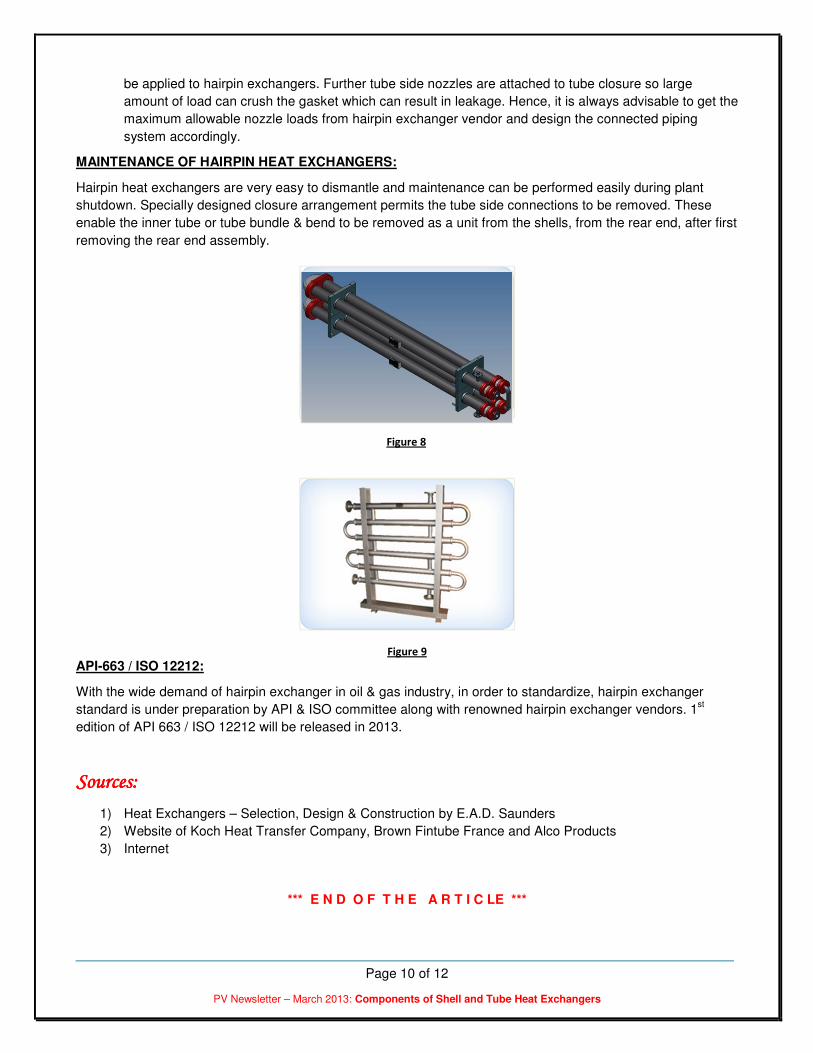
MAINTENANCE OF HAIRPIN HEAT EXCHANGERS:
Hairpin heat exchangers are very easy to dismantle and maintenance can be performed easily during plant
shutdown. Specially designed closure arrangement permits the tube side connections to be removed. These
enable the inner tube or tube bundle & bend to be removed as a unit from the shells, from the rear end, after first
removing the rear end assembly.
API-663 / ISO 12212:
With the wide demand of hairpin exchanger in oil & gas industry, in order to standardize, hairpin exchanger
standard is under preparation by API & ISO committee along with renowned hairpin exchanger vendors. 1st
edition of API 663 / ISO 12212 will be released in 2013.
Sources:Sources:Sources:Sources:
1) Heat Exchangers – Selection, Design & Construction by E.A.D. Saunders
2) Website of Koch Heat Transfer Company, Brown Fintube France and Alco Products
3) Internet
*** E N D O F T H E A R T I C LE ***
Figure 8
Figure 9

Page 11 of 12
PV Newsletter – March 2013: Components of Shell and Tube Heat Exchangers
About CoDesign Engineering:
CoDesign Engineering specializes in the core business of providing training and consultancy for design and
fabrication of ASME code pressure vessels, and the ecosystem that includes piping, welding, valves, geometric
dimensioning and tolerancing, process improvement, and engineering management. Some of the training
courses (lasting from two days to five days) that we provide include:
• Design and Fabrication of ASME Section VIII, Div. 1 Pressure Vessels
• Design and Fabrication of ASME Section VIII, Div. 2 Pressure Vessels
• Shell & Tube Heat Exchangers - Thermal and Mechanical Design
• ASME Section IX - Welding Technology
• Engineering Management
We also provide several one-day workshops:
• Know Your Power Piping
• Know Your Process Piping
• Know Your ASME Section VIII Pressure Vessel Code
• Know Your Shell & Tube Heat Exchangers
• A to Z of Pressure Vessels
• Transitioning to ASME Section VIII, Div. 2
Our trainings can be offered at most cities in India and in US.
Please contact [email protected] for the training calendar and rates.
Visit our website www.codesignengg.com for contents of the courses.

Page 12 of 12
PV Newsletter – March 2013: Components of Shell and Tube Heat Exchangers
Did you like this article?Did you like this article?Did you like this article?Did you like this article?
I would request you to provide me your feedback on the article in this newsletter (and the previous
newsletters as well). I would also request you to send me email addresses for your acquaintances
that would benefit by receiving this newsletter. If you would like to contribute articles, please let me
know. Finally, if you would like the newsletter to be sent to a different email address, or not receive it
at all, kindly email me at [email protected].
Ramesh Tiwari holds a Master’s degree in Mechanical Engineering from Clemson University in South Carolina, and
is a registered Professional Engineer from the state of Maryland in the United States. He has over 22 years of
experience designing pressure vessels, heat exchangers and tanks. Ramesh is a member of ASME Section VIII
Subgroup on Heat Transfer Equipment, and member of ASME B31.1 IWG for Power Piping. He is also an approved
pressure vessel instructor at National Thermal Power Corporation (NTPC), a premier thermal power generating
company in India.
Disclaimer: I feel it is necessary to place a disclaimer statement to protect myself, the contributors and the newsletter. The information provided in this newsletter is for educational purpose only. As a qualified engineer, I take this opportunity to remind all potential users that it is YOUR responsibility to ensure that all designs are verified, and that such designs comply with the current editions of the relevant codes. I accept no liability for any loss or damage which may result from improper use of information in this newsletter.