Embed Size (px)
Citation preview
Putting the audio back in audio/video
White Paper
2
Table of contents
Putting the audio back in audio/video
Introduction 3
Breadth of audio format support 4
“Free run” video mode 5
Full breakaway audio switching 6
Breakaway switching in a DigitalMedia™ transmitter 7
Breakaway switching in a DigitalMedia chassis 8
DSP downmix 11
Using downstream EDIDs to intelligently select the right audio track 13
Integration of DigitalMedia with Sonnex™ 15
HD-DA-2 as a utility device 17
Wrapping it up 18
Crestron, the Crestron logo, DigitalMedia and Sonnex are either trademarks or registered trademarks of Crestron Electronics, Inc. in the United States and/or other countries. iPod is a either a trademark or registered trademark of Apple Inc. in the United States and/or other countries. Dolby and the Dolby logo are either trademarks or registered trademarks of Dolby Laboratories in the United States and/or other countries. DTS-HD and the DTS-HD logo are either trademarks or registered trademarks of DTS, Inc. in the United States and/or other countries. HDMI is a either a trademark or registered trademark of HDMI Licensing LLC in the United States and/or other countries. TOSLINK is either a trademark or registered trademark of Toshiba Corporation in the United States and/or other countries. Other trademarks, registered trademarks, and trade names may be used in this document to refer to either the entities claiming the marks and names or their products. Crestron disclaims any proprietary interest in the marks and names of others. ©2012 Crestron Electronics, Inc.
3
Putting the audio back in audio/video
With its ability to transport high definition digital audio and video, HDMI® is a great format for connecting high-end devices in
point-to-point configurations, or even basic switching systems (e.g., one display, an A/V receiver, and a collection of sources).
However, when there is a need for high definition audio and video in a large and complex distribution environment, HDMI pres-
ents some challenges, especially regarding audio.
To overcome those challenges, a modern digital A/V distribution system must be engineered from the ground up to manage audio
as thoughtfully as it manages video. Too many systems on the market treat audio as merely an afterthought. This shortcoming
results in system designers and integrators having to take on these challenges themselves, with inelegant systems of disparate
components. Time and money must be invested at each job to overcome the same problems, over and over again. Alternatively,
the designer could simplify his design, but the cost is a diminished experience for the end user.
Crestron’s DigitalMedia product line was designed to be the best digital transport network for video and audio signals. Thousands
of hours of engineering and design were invested in building a system that eliminates the complexities of mixing high definition
audio and video in one system. The result is a distribution network that can provide the best possible experience for end users,
without the extra time, equipment, and troubleshooting associated with less evolved approaches to solving HDMI’s
audio challenges.
In this paper, we will investigate some of the situations where DigitalMedia’s sophisticated audio features can improve user experi-
ence, while simplifying design and installation. We will also explore some of the technologies and architectures that
make this possible.
Breadth of audio format support
Introduction
4
The Crestron DigitalMedia product portfolio includes over 70 products, with support for five different types of audio inputs: HDMI,
S/PDIF optical, S/PDIF coaxial, Serial Digital Interface (SDI), and analog stereo. Each of these input types has unique format capa-
bilities, and DigitalMedia supports all major formats for each type of input. Via HDMI, DigitalMedia supports multichannel PCM,
high resolution lossless formats from Dolby (TruHD) and DTS (Master Audio), and the low-bitrate compressed formats (AC-3,
DTS). Using S/PDIF inputs, DigitalMedia can receive stereo PCM or low-bitrate compressed formats. SDI can carry up to eight chan-
nels of PCM audio, and DigitalMedia can receive them all. Finally,
DigitalMedia supports analog stereo inputs.
Any of these input types – digital or analog – can be routed
through a DigitalMedia network to any type of audio sink. If a par-
ticular format is more than an audio sink can handle (for example,
DTS Master Audio routed to a stereo-only TV), then DigitalMedia’s downmixing
DSPs can create a CD-quality stereo mix compatible with the audio sink. (More
on audio downmixing on page 11.) DigitalMedia provides analog outputs for
connectivity to analog-only audio sinks.
It is important to note that all of these audio formats can be routed over any type of DigitalMedia infrastructure – CAT5, multimode
fiber, and single mode fiber. Regardless of your source format and your sink capabilities, DigitalMedia can guarantee your audio is
delivered, reliably, in the highest quality possible.
Breadth of audio format support
It is important to note that all
of these audio formats can
be routed over any type of
DigitalMedia infrastructure –
CAT5, multimode fiber,
and single mode fiber.
5
Putting the audio back in audio/video
HDMI is a high speed video bus. It transmits data in an electrical encoding called transition-minimized digital signaling. While the vast bulk
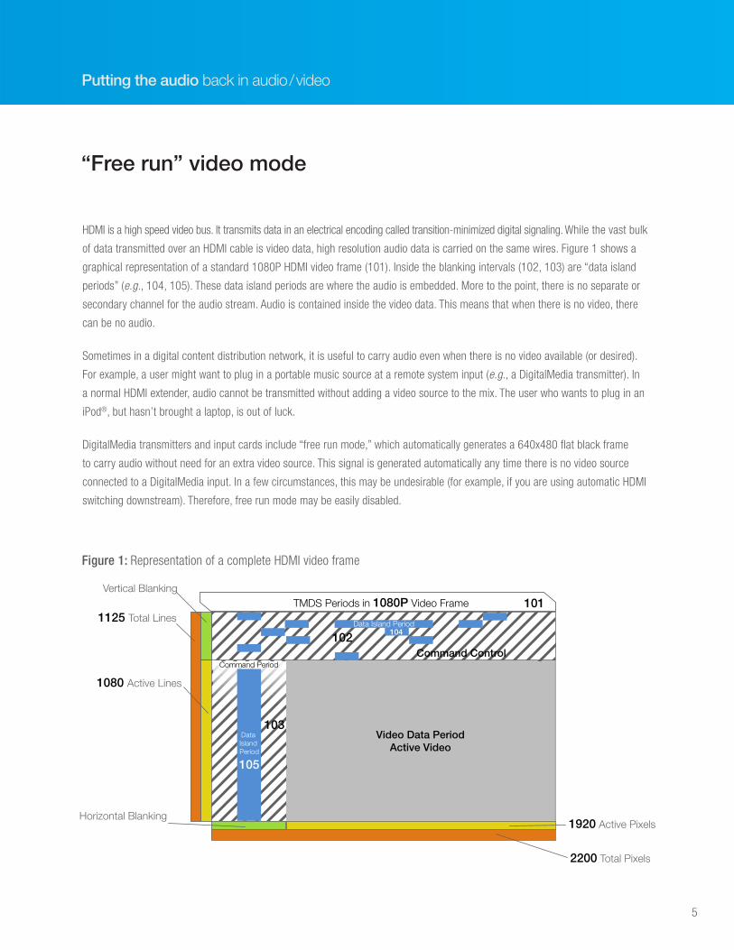
of data transmitted over an HDMI cable is video data, high resolution audio data is carried on the same wires. Figure 1 shows a
graphical representation of a standard 1080P HDMI video frame (101). Inside the blanking intervals (102, 103) are “data island
periods” (e.g., 104, 105). These data island periods are where the audio is embedded. More to the point, there is no separate or
secondary channel for the audio stream. Audio is contained inside the video data. This means that when there is no video, there
can be no audio.
Sometimes in a digital content distribution network, it is useful to carry audio even when there is no video available (or desired).
For example, a user might want to plug in a portable music source at a remote system input (e.g., a DigitalMedia transmitter). In
a normal HDMI extender, audio cannot be transmitted without adding a video source to the mix. The user who wants to plug in an
iPod®, but hasn’t brought a laptop, is out of luck.
DigitalMedia transmitters and input cards include “free run mode,” which automatically generates a 640x480 flat black frame
to carry audio without need for an extra video source. This signal is generated automatically any time there is no video source
connected to a DigitalMedia input. In a few circumstances, this may be undesirable (for example, if you are using automatic HDMI
switching downstream). Therefore, free run mode may be easily disabled.
“Free run” video mode
Video Data PeriodActive Video
Command Control
TMDS Periods in 1080P Video Frame1125 Total Lines
1080 Active Lines
Vertical Blanking
Horizontal Blanking1920 Active Pixels
2200 Total Pixels
103
102 104
101
Data Island Period
Command Period
Data Island Period
105
Figure 1: Representation of a complete HDMI video frame
6
Full breakaway audio switching
The most basic digital audio and video
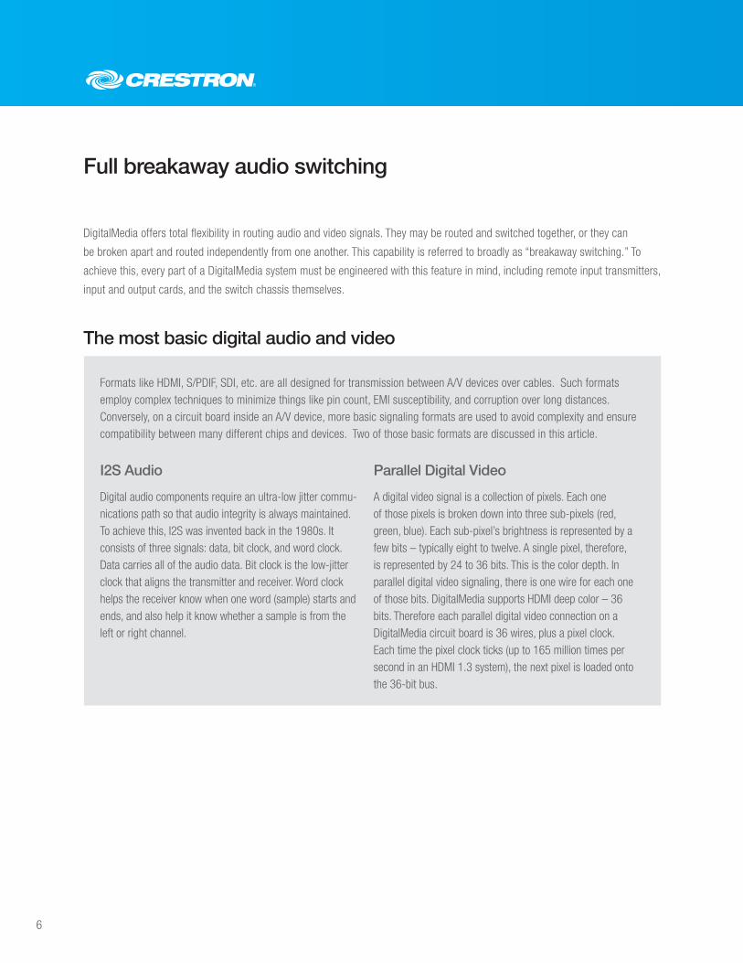
DigitalMedia offers total flexibility in routing audio and video signals. They may be routed and switched together, or they can
be broken apart and routed independently from one another. This capability is referred to broadly as “breakaway switching.” To
achieve this, every part of a DigitalMedia system must be engineered with this feature in mind, including remote input transmitters,
input and output cards, and the switch chassis themselves.
Digital audio components require an ultra-low jitter commu-nications path so that audio integrity is always maintained. To achieve this, I2S was invented back in the 1980s. It consists of three signals: data, bit clock, and word clock. Data carries all of the audio data. Bit clock is the low-jitter clock that aligns the transmitter and receiver. Word clock helps the receiver know when one word (sample) starts and ends, and also help it know whether a sample is from the left or right channel.
A digital video signal is a collection of pixels. Each one of those pixels is broken down into three sub-pixels (red, green, blue). Each sub-pixel’s brightness is represented by a few bits – typically eight to twelve. A single pixel, therefore, is represented by 24 to 36 bits. This is the color depth. In parallel digital video signaling, there is one wire for each one of those bits. DigitalMedia supports HDMI deep color – 36 bits. Therefore each parallel digital video connection on a DigitalMedia circuit board is 36 wires, plus a pixel clock. Each time the pixel clock ticks (up to 165 million times per second in an HDMI 1.3 system), the next pixel is loaded onto the 36-bit bus.
Formats like HDMI, S/PDIF, SDI, etc. are all designed for transmission between A/V devices over cables. Such formats employ complex techniques to minimize things like pin count, EMI susceptibility, and corruption over long distances. Conversely, on a circuit board inside an A/V device, more basic signaling formats are used to avoid complexity and ensure compatibility between many different chips and devices. Two of those basic formats are discussed in this article.
I2S Audio Parallel Digital Video
7
Putting the audio back in audio/video
Breakaway switching in a DigitalMedia transmitter
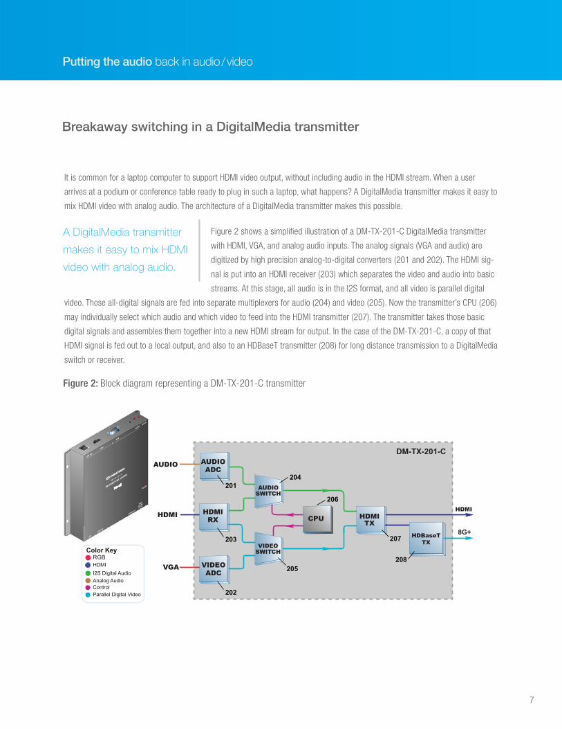
It is common for a laptop computer to support HDMI video output, without including audio in the HDMI stream. When a user
arrives at a podium or conference table ready to plug in such a laptop, what happens? A DigitalMedia transmitter makes it easy to
mix HDMI video with analog audio. The architecture of a DigitalMedia transmitter makes this possible.
Figure 2 shows a simplified illustration of a DM-TX-201-C DigitalMedia transmitter
with HDMI, VGA, and analog audio inputs. The analog signals (VGA and audio) are
digitized by high precision analog-to-digital converters (201 and 202). The HDMI sig-
nal is put into an HDMI receiver (203) which separates the video and audio into basic
streams. At this stage, all audio is in the I2S format, and all video is parallel digital
video. Those all-digital signals are fed into separate multiplexers for audio (204) and video (205). Now the transmitter’s CPU (206)
may individually select which audio and which video to feed into the HDMI transmitter (207). The transmitter takes those basic
digital signals and assembles them together into a new HDMI stream for output. In the case of the DM-TX-201-C, a copy of that
HDMI signal is fed out to a local output, and also to an HDBaseT transmitter (208) for long distance transmission to a DigitalMedia
switch or receiver.
A DigitalMedia transmitter
makes it easy to mix HDMI
video with analog audio.
HDMI
VGA
HDMIRX
AUDIOADC
VIDEOADC
VIDEOSWITCH
HDMITX
AUDIO
HDMI
HDBaseTTX
AUDIOSWITCH
DM-TX-201-C
CPU
8G+
208
207
205
204
206
201
203
202
RGB
I2S Digital Audio
Color Key
ControlParallel Digital Video
HDMI
Analog Audio
USB HID
HDMI
RGB
AUDIOSETUP
D M - T X - 2 0 1 - C
D M C O M P U T E R C E N T E R
RESET
IN
LAN
DM OUT
HDMI OUT
PWR
24 VDC
0.75A
Figure 2: Block diagram representing a DM-TX-201-C transmitter
8
In a DigitalMedia matrix switch, audio and video may be routed with complete
independence. Any audio input may be combined with any video input, and the
combination may be routed to any output. Also recall that audio may be routed on
its own (thanks to free run mode, described earlier). Different mixes of audio/video
inputs may be used at each output, thanks to the extremely flexible architecture of
DigitalMedia switches.
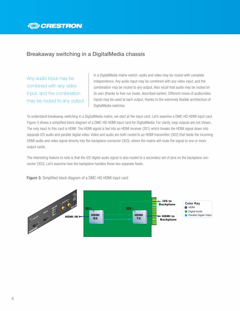
To understand breakaway switching in a DigitalMedia matrix, we start at the input card. Let’s examine a DMC-HD HDMI input card.
Figure 3 shows a simplified block diagram of a DMC-HD HDMI input card for DigitalMedia. For clarity, loop outputs are not shown.
The only input to this card is HDMI. The HDMI signal is fed into an HDMI receiver (301) which breaks the HDMI signal down into
separate I2S audio and parallel digital video. Video and audio are both routed to an HDMI transmitter (302) that feeds the incoming
HDMI audio and video signal directly into the backplane connector (303), where the matrix will route the signal to one or more
output cards.
The interesting feature to note is that the I2S digital audio signal is also routed to a secondary set of pins on the backplane con-
nector (303). Let’s examine how the backplane handles these two separate feeds.
Breakaway switching in a DigitalMedia chassis
Any audio input may be
combined with any video
input, and the combination
may be routed to any output.
HDMIRXHDMI IN
I2S toBackplane
HDMI toBackplane
HDMITX
Digital Audio
Color Key
Parallel Digital Video
HDMI301 302
AUDIO OUTR
L
HDMI OUT
HDMI IN
USB HIDDMC-HD
Figure 3: Simplified block diagram of a DMC-HD HDMI input card
9
Putting the audio back in audio/video
INPUTCARD
HDMIRX
HDMIRX
INPUTCARD
HDMI
AUDIOSWITCH
HDMITX
CPU
OUTPUTCARD
I2S Digital Audio
Color Key
ControlParallel Digital Video
HDMI
AudioCrossPoint
HDMICrossPoint
BackPlane
401
402
403
407
408
409
OUTPUTCARD
404
405
406
CPU
HDMITX
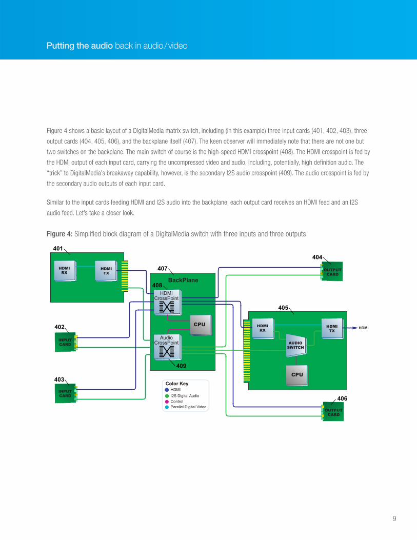
Figure 4: Simplified block diagram of a DigitalMedia switch with three inputs and three outputs
Figure 4 shows a basic layout of a DigitalMedia matrix switch, including (in this example) three input cards (401, 402, 403), three
output cards (404, 405, 406), and the backplane itself (407). The keen observer will immediately note that there are not one but
two switches on the backplane. The main switch of course is the high-speed HDMI crosspoint (408). The HDMI crosspoint is fed by
the HDMI output of each input card, carrying the uncompressed video and audio, including, potentially, high definition audio. The
“trick” to DigitalMedia’s breakaway capability, however, is the secondary I2S audio crosspoint (409). The audio crosspoint is fed by
the secondary audio outputs of each input card.
Similar to the input cards feeding HDMI and I2S audio into the backplane, each output card receives an HDMI feed and an I2S
audio feed. Let’s take a closer look.
10
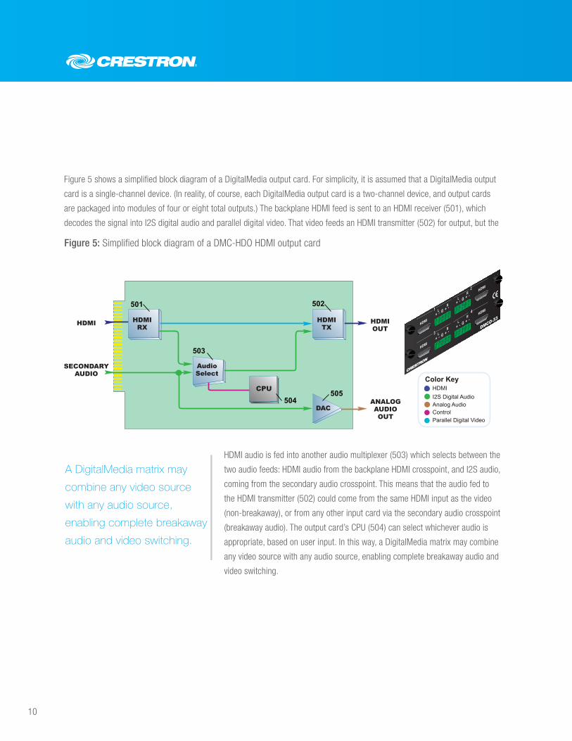
Figure 5 shows a simplified block diagram of a DigitalMedia output card. For simplicity, it is assumed that a DigitalMedia output
card is a single-channel device. (In reality, of course, each DigitalMedia output card is a two-channel device, and output cards
are packaged into modules of four or eight total outputs.) The backplane HDMI feed is sent to an HDMI receiver (501), which
decodes the signal into I2S digital audio and parallel digital video. That video feeds an HDMI transmitter (502) for output, but the
HDMI audio is fed into another audio multiplexer (503) which selects between the
two audio feeds: HDMI audio from the backplane HDMI crosspoint, and I2S audio,
coming from the secondary audio crosspoint. This means that the audio fed to
the HDMI transmitter (502) could come from the same HDMI input as the video
(non-breakaway), or from any other input card via the secondary audio crosspoint
(breakaway audio). The output card’s CPU (504) can select whichever audio is
appropriate, based on user input. In this way, a DigitalMedia matrix may combine
any video source with any audio source, enabling complete breakaway audio and
video switching.
AudioSelect
HDMIOUT
HDMIRX
DAC
HDMI
ANALOGAUDIOOUT
SECONDARYAUDIO
HDMITX
I2S Digital AudioAnalog Audio
Color Key
ControlParallel Digital Video
HDMICPU
501
503
504505
502
DMCO-33
1
2
3
4
HDMI
HDMI
HDMI
HDMIL R
L R
L R
L R
+ - G + -
+ - G + -
+ - G + -
+ - G + -
Figure 5: Simplified block diagram of a DMC-HDO HDMI output card
A DigitalMedia matrix may
combine any video source
with any audio source,
enabling complete breakaway
audio and video switching.
11
Putting the audio back in audio/video
We have established that DigitalMedia is a complete video and audio switch, with
full breakaway audio routing capability to complement the powerful video routing
capabilities of the switch. But what if your audio sinks have different capabilities
than one another? Home theater audio is typically managed by a powerful HDMI
A/V receiver, supporting all the latest and greatest high definition audio formats such as Dolby® TruHD and DTS Master Audio.
That’s great, but the TV in the kitchen can only support stereo PCM audio. HDMI itself can only carry a single audio stream – high
definition, or stereo. Not both.
How the secondary audio matrix enables multiple audio tracks
DSP downmix
What if your audio sinks
have different capabilities
than one another?
Traditionally there are two approaches to solve this problem:
1. Manage your high-quality HDMI audio in your HDMI matrix, leaving stereo audio management to an entirely separate distribution
system. This approach requires that you limit your sources to those devices which can simultaneously output high definition
HDMI audio and low quality analog audio, and requires you to manage the expense, cabling, and integration of two complex and
disparate systems.
2. Give up your high definition audio. Configure your sources to output stereo only and route these signals through your HDMI
distribution system.
Obviously, neither of these choices is ideal.
DigitalMedia solves this problem elegantly by taking advantage of the sec-
ondary audio crosspoint and adding in some audio DSP horsepower to create
its own stereo downmix of high definition audio content. Unlike traditional
HDMI, DigitalMedia can carry two separate audio streams simultaneously.
Unlike traditional HDMI,
DigitalMedia can carry two
separate audio
streams simultaneously.
12
INPUTCARD
HDMIRX
HDMIRX
INPUTCARD
CPUHDMI
AUDIOSWITCH
HDMITX
CPU
OUTPUTCARD
I2S Digital Audio
Color Key
ControlParallel Digital Video
HDMI
AudioCrossPoint
HDMICrossPoint
BackPlane
702
701
OUTPUTCARD
DSP
HDMITX
HDMI
Figure 7: Simplified block diagram of a DigitalMedia switch with DSP input cards
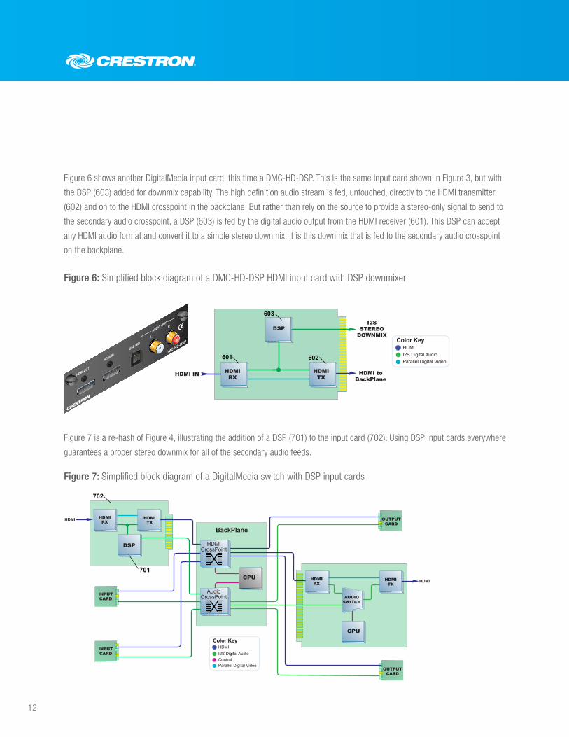
Figure 6 shows another DigitalMedia input card, this time a DMC-HD-DSP. This is the same input card shown in Figure 3, but with
the DSP (603) added for downmix capability. The high definition audio stream is fed, untouched, directly to the HDMI transmitter
(602) and on to the HDMI crosspoint in the backplane. But rather than rely on the source to provide a stereo-only signal to send to
the secondary audio crosspoint, a DSP (603) is fed by the digital audio output from the HDMI receiver (601). This DSP can accept
any HDMI audio format and convert it to a simple stereo downmix. It is this downmix that is fed to the secondary audio crosspoint
on the backplane.
Figure 7 is a re-hash of Figure 4, illustrating the addition of a DSP (701) to the input card (702). Using DSP input cards everywhere
guarantees a proper stereo downmix for all of the secondary audio feeds.
Figure 6: Simplified block diagram of a DMC-HD-DSP HDMI input card with DSP downmixer
HDMIRX
DSP
HDMI IN
I2SSTEREO
DOWNMIX
HDMI toBackPlane
HDMITX
I2S Digital Audio
Color Key
Parallel Digital Video
HDMI
601
603
602
AUDIO OUT
L
R
USB HID
HDMI OUT
HDMI INDMC-HD-DSP
13
Putting the audio back in audio/video
Using downstream EDIDs to intelligently select the right audio track
Refer back to Figure 5, showing a DigitalMedia HDMI output card. Imagine we are not using breakaway audio; the HDMI audio sig-
nal and secondary audio signals coming from the backplane are both from the same input card (and therefore the same source).
Now, however, the HDMI audio is high definition multichannel and the secondary audio is its stereo downmix. Obviously we need
the stereo downmix to feed the DAC (505) for analog output, but what about the HDMI output? How will the user know which audio
track to feed to the HDMI output? How will the user make this selection?
In fact, the user will not need to be involved at all. Neither will the system integrator or programmer. DigitalMedia will intelligently
and automatically select the correct audio track by checking the EDID of the downstream device it detects on its HDMI output.
14
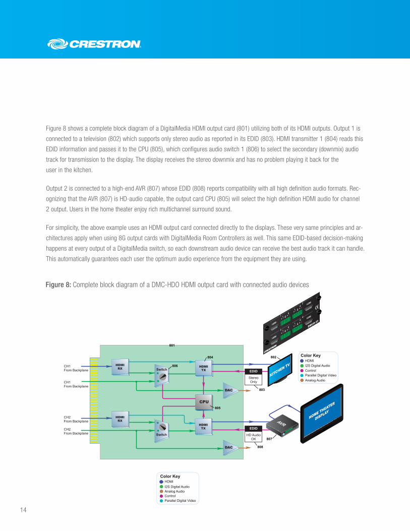
Figure 8 shows a complete block diagram of a DigitalMedia HDMI output card (801) utilizing both of its HDMI outputs. Output 1 is
connected to a television (802) which supports only stereo audio as reported in its EDID (803). HDMI transmitter 1 (804) reads this
EDID information and passes it to the CPU (805), which configures audio switch 1 (806) to select the secondary (downmix) audio
track for transmission to the display. The display receives the stereo downmix and has no problem playing it back for the
user in the kitchen.
Output 2 is connected to a high-end AVR (807) whose EDID (808) reports compatibility with all high definition audio formats. Rec-
ognizing that the AVR (807) is HD-audio capable, the output card CPU (805) will select the high definition HDMI audio for channel
2 output. Users in the home theater enjoy rich multichannel surround sound.
For simplicity, the above example uses an HDMI output card connected directly to the displays. These very same principles and ar-
chitectures apply when using 8G output cards with DigitalMedia Room Controllers as well. This same EDID-based decision-making
happens at every output of a DigitalMedia switch, so each downstream audio device can receive the best audio track it can handle.
This automatically guarantees each user the optimum audio experience from the equipment they are using.
Figure 8: Complete block diagram of a DMC-HDO HDMI output card with connected audio devices
HDMIRX
HDMIRX
I2S Digital Audio
Color Key
ControlParallel Digital Video
HDMI
HDMITX
CH1 From Backplane
CH1 From Backplane
CH2 From Backplane
CH2 From Backplane
806
804
801
Switch
Switch
CPU
HDMITX
805
KITCHEN TV
HOME THEATER
DISPLAY
AVR
803
807
808
EDID
HD AudioOK
EDID
StereoOnly
I2S Digital AudioAnalog Audio
Color Key
ControlParallel Digital Video
HDMI
802
Analog Audio
DAC
DAC
DMCO-33
1
2
3
4
HDMI
HDMI
HDMI
HDMIL R
L R
L R
L R
+ - G + -
+ - G + -
+ - G + -
+ - G + -
15
Putting the audio back in audio/video
Integration of DigitalMedia with Sonnex
DigitalMedia is a great solution for routing video and audio throughout a facility. Still, there are many applications that call for a
separate and dedicated audio distribution system, like Crestron Sonnex™ or with an external mixing console. This is especially
true when there are many more audio-only zones than A/V zones. DigitalMedia is engineered to easily integrate with your audio
distribution system.
A key problem for the integration of audio and video systems is sharing of sources. If your source only has a single output, you
must include extra signal splitters or DAs to connect it to both systems. You may also need to convert digital outputs to analog,
depending on the capabilities of your source and your audio distribution system. DigitalMedia makes this integration simple by
providing audio loop outputs for each system input.
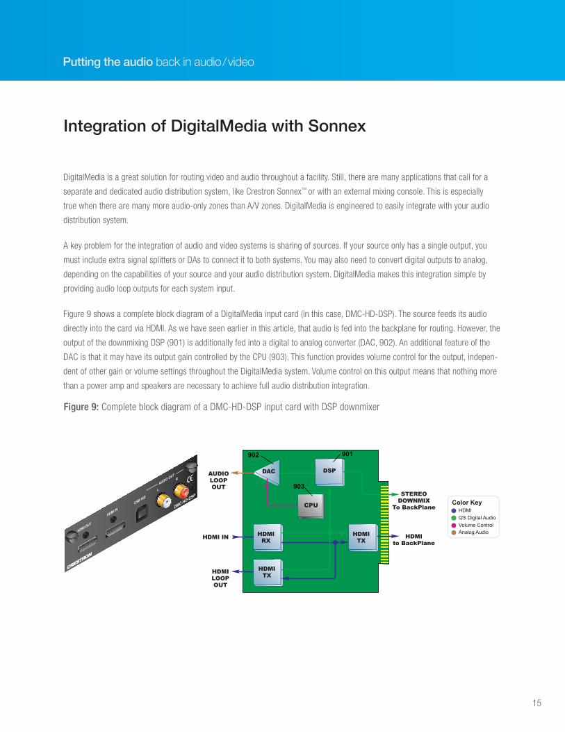
Figure 9 shows a complete block diagram of a DigitalMedia input card (in this case, DMC-HD-DSP). The source feeds its audio
directly into the card via HDMI. As we have seen earlier in this article, that audio is fed into the backplane for routing. However, the
output of the downmixing DSP (901) is additionally fed into a digital to analog converter (DAC, 902). An additional feature of the
DAC is that it may have its output gain controlled by the CPU (903). This function provides volume control for the output, indepen-
dent of other gain or volume settings throughout the DigitalMedia system. Volume control on this output means that nothing more
than a power amp and speakers are necessary to achieve full audio distribution integration.
HDMIRX
DAC
HDMITX
DSPAUDIOLOOPOUT
HDMI IN
HDMILOOPOUT
STEREODOWNMIX
To BackPlane
HDMIto BackPlane
HDMITX
I2S Digital Audio
Color Key
Volume ControlAnalog Audio
HDMICPU
901
903
902
AUDIO OUT
L
R
USB HID
HDMI OUT
HDMI INDMC-HD-DSP
Figure 9: Complete block diagram of a DMC-HD-DSP input card with DSP downmixer
16
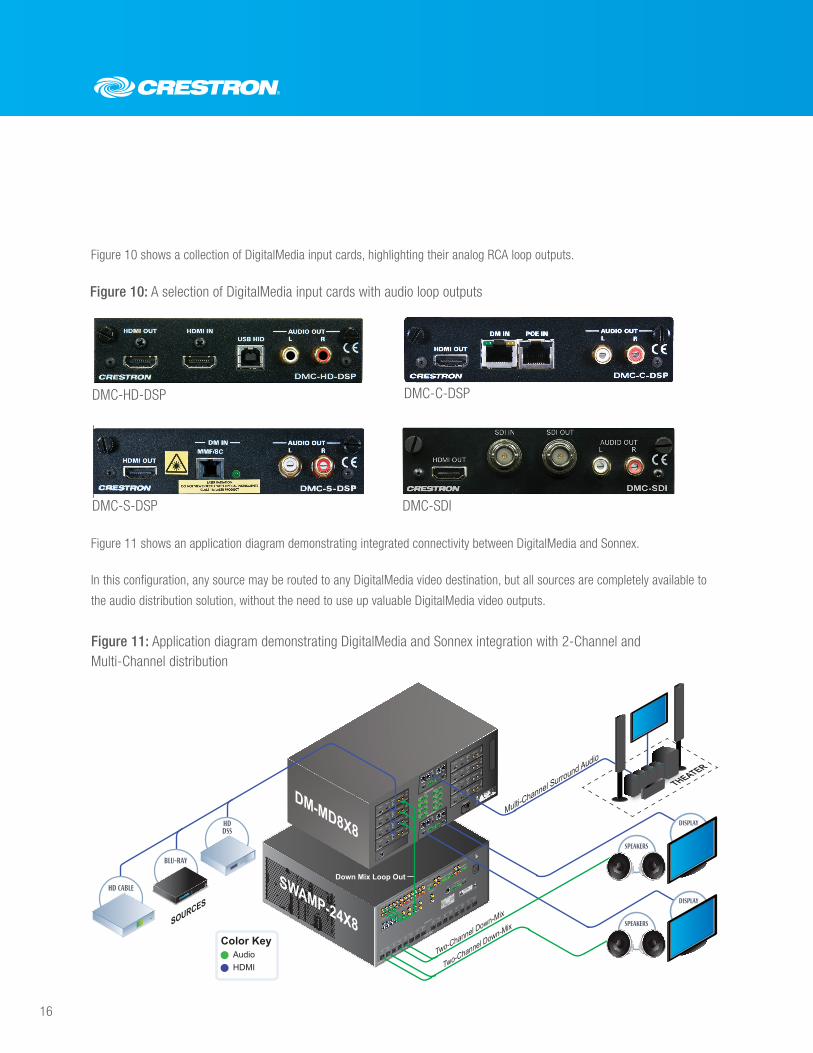
Figure 10 shows a collection of DigitalMedia input cards, highlighting their analog RCA loop outputs.
Figure 11 shows an application diagram demonstrating integrated connectivity between DigitalMedia and Sonnex.
In this configuration, any source may be routed to any DigitalMedia video destination, but all sources are completely available to
the audio distribution solution, without the need to use up valuable DigitalMedia video outputs.
4
7
CAUTION
RISK OF ELECTRIC SHOCK
DO NOT OPEN
AVIS: RISQUE DE CHOC ELECTRIQUE NE PAS OUVRIR
LEFT B
RIDGE RIGHT
+ -
+ -
8 OHMS ONLY
+ -
LEFT
RIGHT
LEFT
RIGHT
LEFT
RIGHT
LEFT
RIGHT
LEFT
RIGHT
LEFT
RIGHT
LEFT
RIGHT
LEFT
RIGHT
+ -
+ -
+ -
+ -
+ -
+ -
+ -
+ -
+ -
+ -
+ -
+ -
+ -
+ -
+ -
1
2
3
4
5
6
7
8
SPEAKER OUTPUTS
8Ω 120 W 4Ω 240 W
CLASS 2 WIRING
ELECTRONICS INC. ROCKLEIGH, N.J. 07647 USA
ANALOG SOURCES
BALANCED
+ - G + -
BALANCED
+ - G + -
BALANCED
+ - G + -
BALANCED
+ - G + -
SPDIF OUT
LOOP THRU
24 Y Z G24 Y Z G
SETUP
SPDIF SOURCES
DIGITAL OUT
L
R
1
2
3
4
5
6
7
8
9
10
11 1
2
1
2
3
4
5
6
7
8
17
18
19
20
21
22
23
24
13
14
15
16
10
9
LAN
G
DM OUTPUTS
DM OUTPUTS
100-250V~4.0A
50/60 Hz
24 A B GE I G
24 A B GE I G
24 A B GE I G
24 A B GE I G
24 A B GE I G
24 A B GE I G
24 A B GE I G
24 A B GE I G
AUDIO OUTR
L
HDMI OUT
HDMI IN
USB HID
DMC-HD-DSP
AUDIO OUTR
L
HDMI OUT
HDMI IN
USB HID
DMC-HD-DSP
AUDIO OUTR
L
HDMI OUT
HDMI IN
USB HID
DMC-HD-DSP
AUDIO OUTR
L
HDMI OUT
HDMI IN
USB HID
DMC-HD-DSP
AUDIO OUTR
L
HDMI OUT
HDMI IN
USB HID
DMC-HD-DSP
AUDIO OUTR
L
HDMI OUT
HDMI IN
USB HID
DMC-HD-DSP
AUDIO OUTR
L
HDMI OUT
HDMI IN
USB HID
DMC-HD-DSP
AUDIO OUTR
L
HDMI OUT
HDMI IN
USB HID
DMC-HD-DSP
DM-MD8X8
SWAMP-24X8
LAN
Color KeyAudioHDMI
HDMI
DM OUTPOE IN
+ - G + -
POE IN
DMCO-53
DM OUT
HDMI
HDMI
+ - G + -
HDMI
DM OUTPOE IN
+ - G + -
POE IN
DMCO-53
DM OUT
HDMI
HDMI
+ - G + -
DISPLAY
SPEAKERS
THEATER
Two-Channel Down-Mix
Two-Channel Down-Mix
Down Mix Loop Out
DISPLAY
BLU-RAY
TM
HDDSS
SOURCES
HD CABLE
SPEAKERS
Multi-Channel Surround Audio
Figure 11: Application diagram demonstrating DigitalMedia and Sonnex integration with 2-Channel and Multi-Channel distribution
DMC-HD-DSP
DMC-S-DSP
DMC-C-DSP
DMC-SDI
Figure 10: A selection of DigitalMedia input cards with audio loop outputs
17
Putting the audio back in audio/video
Not only is the HD-DA-2 a reliable, HDCP-compliant HDMI distribution amp, it is also a handy audio problem solver. Perhaps your
source is a PC with DVI video and S/PDIF audio. The HD-DA-2 can combine the S/PDIF audio from a TOSLINK® or coax source with
HDMI video and provide dual HDMI outputs with this new mix of audio and video.
Or perhaps your source is HDMI-only, but you need to feed the audio into an analog pre-amp or audio distribution system. HD-
DA-2 can extract stereo audio from an HDMI signal, convert the audio to analog, and send that signal out via RCA jacks. Connect
the analog outputs to your audio distribution system and HDMI outputs to your display. Additionally, the HD-DA-2 can be used as a
pure extractor, without connecting a display.
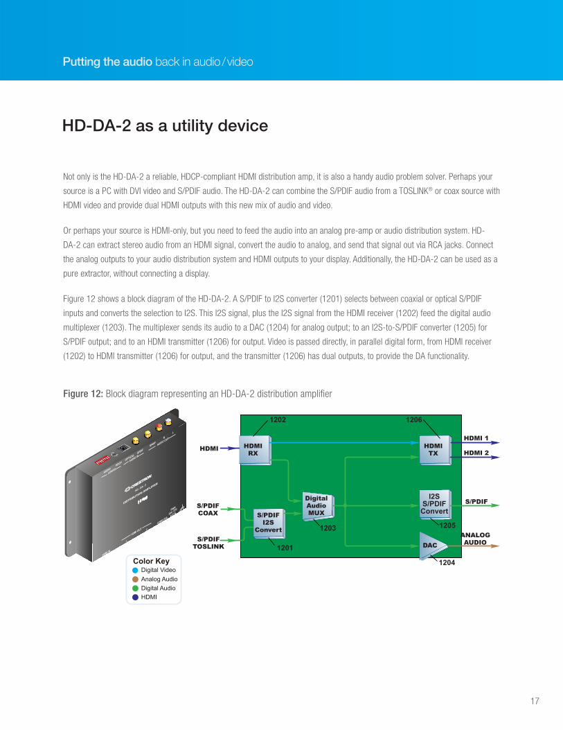
Figure 12 shows a block diagram of the HD-DA-2. A S/PDIF to I2S converter (1201) selects between coaxial or optical S/PDIF
inputs and converts the selection to I2S. This I2S signal, plus the I2S signal from the HDMI receiver (1202) feed the digital audio
multiplexer (1203). The multiplexer sends its audio to a DAC (1204) for analog output; to an I2S-to-S/PDIF converter (1205) for
S/PDIF output; and to an HDMI transmitter (1206) for output. Video is passed directly, in parallel digital form, from HDMI receiver
(1202) to HDMI transmitter (1206) for output, and the transmitter (1206) has dual outputs, to provide the DA functionality.
HD-DA-2 as a utility device
DigitalAudioMUX
HDMI 1
HDMI 2
Analog AudioDigital AudioHDMI
Color KeyDigital Video
HDMIRX
HDMITX
S/PDIFCOAX
S/PDIFTOSLINK
HDMI
S/PDIF
ANALOGAUDIO
S/PDIFI2S
Convert
1202 1206
I2SS/PDIFConvert
1201
1203
1204
1205
DAC
AUDIO HDCP
OPTICAL SPDIF
SPDIF
R
L
CONFIG
AUDIO IN
AUDIO OUT
HD - DA - 2
DISTRIBUTION AMPLIFIER
HDMI OUT
HDMI IN
1
2
C
OMPUTER
PWR
24V0.21A
Figure 12: Block diagram representing an HD-DA-2 distribution amplifier
18
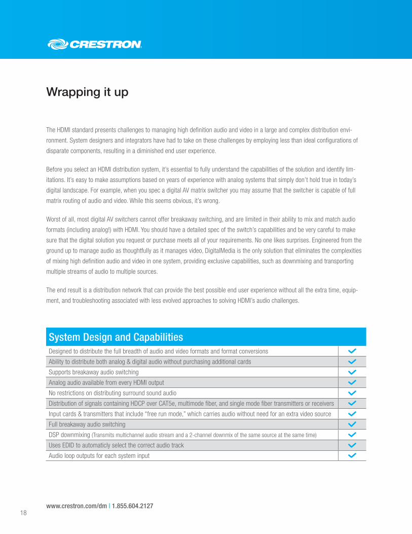
The HDMI standard presents challenges to managing high definition audio and video in a large and complex distribution envi-
ronment. System designers and integrators have had to take on these challenges by employing less than ideal configurations of
disparate components, resulting in a diminished end user experience.
Before you select an HDMI distribution system, it’s essential to fully understand the capabilities of the solution and identify lim-
itations. It’s easy to make assumptions based on years of experience with analog systems that simply don’t hold true in today’s
digital landscape. For example, when you spec a digital AV matrix switcher you may assume that the switcher is capable of full
matrix routing of audio and video. While this seems obvious, it’s wrong.
Worst of all, most digital AV switchers cannot offer breakaway switching, and are limited in their ability to mix and match audio
formats (including analog!) with HDMI. You should have a detailed spec of the switch’s capabilities and be very careful to make
sure that the digital solution you request or purchase meets all of your requirements. No one likes surprises. Engineered from the
ground up to manage audio as thoughtfully as it manages video, DigitalMedia is the only solution that eliminates the complexities
of mixing high definition audio and video in one system, providing exclusive capabilities, such as downmixing and transporting
multiple streams of audio to multiple sources.
The end result is a distribution network that can provide the best possible end user experience without all the extra time, equip-
ment, and troubleshooting associated with less evolved approaches to solving HDMI’s audio challenges.
Wrapping it up
www.crestron.com/dm | 1.855.604.2127
System Design and CapabilitiesDesigned to distribute the full breadth of audio and video formats and format conversions
Ability to distribute both analog & digital audio without purchasing additional cards
Supports breakaway audio switching
Analog audio available from every HDMI output
No restrictions on distributing surround sound audio
Distribution of signals containing HDCP over CAT5e, multimode fiber, and single mode fiber transmitters or receivers
Input cards & transmitters that include “free run mode,” which carries audio without need for an extra video source
Full breakaway audio switching
DSP downmixing (Transmits multichannel audio stream and a 2-channel downmix of the same source at the same time)
Uses EDID to automaticly select the correct audio track
Audio loop outputs for each system input


![MG_RG_SDK-X_Introduction_Tutorial_1 [Crestron]](https://img.pdfslide.us/doc/110x75/61911ef5eb807b51a5439990/mgrgsdk-xintroductiontutorial1-crestron.jpg)