Embed Size (px)
Citation preview

Advanced Enzyme-Catalyzed CO2 Capture in Low-Energy Solvents
Alex Zaks, Ph.D.
2012 NETL CO2 Capture Technology Meeting
Pittsburgh, PA July 9-12, 2012
Putting enzymes to work™

• Acknowledgement: This material is based upon work supported by the Department of Energy National Energy Technology Laboratory under Award Number DE-FE0004228.
• Disclaimer: This presentation was prepared as an account of work sponsored by
an agency of the United States Government. Neither the United States Government nor any agency thereof, nor any of their employees, makes any warranty, express or implied, or assumes any legal liability or responsibility for the accuracy, completeness, or usefulness of any information, apparatus, product, or process disclosed, or represents that completeness, or usefulness of any information, apparatus, product, or process disclosed, or represents that its use would not infringe privately owned rights. Reference herein to any specific commercial product, process, or service by trade name, trademark, manufacturer, or otherwise does not necessarily constitute or imply its endorsement, recommendation, or favoring by the United States Government or any agency thereof. The views and opinions of authors expressed herein do not necessarily state or reflect those of the United States Government or any agency.
2

AKERMIN, INC.
• St. Louis-based biotechnology company
• Developing next generation cost and energy efficient, environmentally benign systems for CO2 capture
• Technology based on integrating an enzyme within a proprietary biocatalyst delivery system which permits: • Use of low energy solutions of carbonates
• Incorporation into a traditional chemical absorption process
3

PROJECT OVERVIEW
• Project participants
• Project duration: 33 months (initiated in October 2010)
• Funding Total Project: $ 4,749,469
DOE Funding: $ 2,909,678
Akermin Cost share: $ 1,839,791
4

PROJECT OBJECTIVES
• Engineer Bench-Scale Carbon Capture System
– ~5 kWe (500 SLPM flue gas)
• Demonstrate 90% CO2 capture from flue gas in a bench-scale unit in the presence of biocatalyst and potassium carbonate
• Characterize rate enhancement of biocatalyst
• Demonstrate tolerance to flue gas impurities
• Evaluate impact of external conditions on process performance
• Demonstrate CO2 capture on flue gas for duration of 6 months
• Generate process data to further refine simulation models
• Model and evaluate the capital and operational costs for full-scale coal-fired power plant
5

6 Confidential to Akermin, Inc.

TECHNOLOGY FUNDAMENTALS Basic unit design for CO2 capture incorporating biocatalyst
7
45 oC
105 oC
FLUE GAS
STEAM
CONDENSATE
CROSS EXCHANGER
PUMP “LEAN
PRODUCT GAS
ID FAN
PRODUCT CO 2
CONDENSER
ADVANCED CO 2 COMPRESSION
REBOILER
VAPOR
STRIPPER
ABSORBER
Akermin Inc . ( 2011 )
LIQUID
Biocatalyst delivery system
K2CO3/KHCO3 lean solution
K2CO3/KHCO3 reach solution

THERMOSTABILITY OF FREE CARBONIC ANHYDRASE
0%
20%
40%
60%
80%
100%
120%
140%
0 20 40 60 80 100 120 140 160 180 200 220 240
Perc
ent
Rel
ativ
e R
ate
Lifetime (days)
Room Temp. 40 ° C 50 ° C 60° C 70° C 80° C
T1/2 ~ 110 days at 40 oC T1/2 ~ 60 days at 50 oC T1/2 <1 day at 80 oC
8
40 oC
22 oC
50 oC
60 oC
70 oC 80 oC
0.5 M K2CO3/0.5 M KHCO3, pH 10.0

CHARACTERISTICS OF BIOCATALYST DELIVERY SYSTEM
• Compatible with commercial mass transfer devices
• Impose minimal internal diffusional limitations – CO2 permeable or highly porous support
• Provide protective environment against inactivation by temperature, solvents, and shear forces
– Encapsulation/entrapment-based
• Low cost, scalable – Commercially available starting materials; simple one/two-
step protocol
9
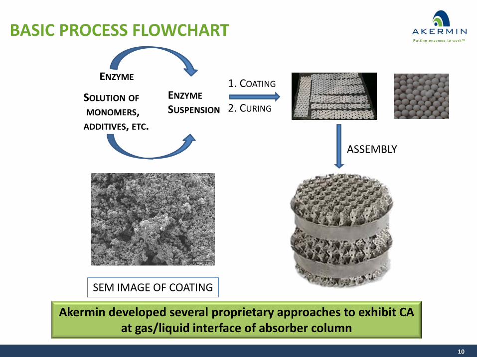
BASIC PROCESS FLOWCHART
10
Akermin developed several proprietary approaches to exhibit CA at gas/liquid interface of absorber column
ENZYME
SOLUTION OF MONOMERS, ADDITIVES, ETC.
ENZYME SUSPENSION
1. COATING
2. CURING
ASSEMBLY
SEM IMAGE OF COATING

PERFORMANCE OF BIOCATALYST IN A COUNTER-CURRENT FLOW COLUMN
11
Up to 22-fold increase of KG was demonstrated
20% carbonate (w/w) pH 10.1; p = 1 psig; CO2 absorption at 45oC;
KG per packing area, lab-scale test reactor interfacial area ~ 30%

BIOCATALYST MAXIMIZES MASS TRANSFER AND REDUCES COLUMN HEIGHT
*Aspen Plus modeling by PNNL
12
10X 16X
Enhancement over 10X reduces the absorber height to less than 130 feet for a 550 mWe coal-fired power plant*
4X

STUDY OF CA INHIBITION BY PRODUCTS OF HYDRATION OF FLUE GAS IMPURITIES Solution study
Contaminant
Anticipated Concentration
Soluble Product IC50 (mM)
NOX ~80 ppm Nitrate (NO3
-) ~ 1000
Nitrite (NO2-) > 2000
SOX ~45 ppm Sulfate (SO4
-2) > 500
Sulfite (SO3-2) >> 10
Chloride < 1ppm Chloride (Cl-) > 2000
13
Sulfate, sulfite, nitrate, nitrite and chloride have little or no inhibitory potency

TESTING ON FLUE GAS
• Evaluate resistance of the biocatalyst delivery system to Hg, SOx and NOx
• Demonstrate endurance performance using actual flue gas
– Flue gas was generated at the Advanced Coal and Energy Research Facility at Washington University in St. Louis
– Flue gas was gathered into a 10 m3 bag from a short duration combustion test
14

50%
55%
60%
65%
70%
75%
80%
85%
90%
95%
100%
0 5 10 15 20 25
CO2 C
aptu
red
(% C
O2 f
low
)
Time (Days)
Coal Flue Gas at Wash U
Reference Sample Reference Mixture
TESTING ON FLUE GAS
15
~ 90-95% CO2 capture sustained for over 23 days on flue gas (~14% feed) ~ 90-92% CO2 capture on Reference Mixture (~15% CO2 in air) for 14 days
Overall performance is stable in both cases
Wyoming Powder River Basin subbituminous coal

STUDY OF TRACE CONTAMINANTS: 20 PPM SO2 AND 20 PPM NO2
16
0%
10%
20%
30%
40%
50%
60%
70%
80%
90%
100%
0 1 2 3 4 5 6 7 8
CO2 C
aptu
red
(% C
O2 f
low
)
DCP-9-3 with neat gas
DCP-9-3 with 20 ppm SO2 + 20 ppm NO2
~90% capture maintained over the duration of the experiment
Time on stream (days)

0%
10%
20%
30%
40%
50%
60%
70%
80%
90%
100%
0 10 20 30 40 50 60 70 80 90
CO2 C
aptu
re (%
)
Time on Stream (Days)
LONG-TERM PERFORMANCE OF CLOSED LOOP REACTOR
400 mL/min 15% CO2; 20% carbonate (w/w) pH 10.1; p = 1 psig; CO2 absorption at 45oC;
thermal swing desorption at 105oC
>20 million CO2 molecules hydrated by one CA molecule over 75 days Initial performance >400 kg CO2 captured per day per kg of CA
Akermin’s Closed Loop Reactor
Biocatalyst delivery system
Soluble enzyme
17
Gas Flow Out
Absorber Column
CO2 Gas Flow In
Reboiler
Desorber Column
CO2 Gas Out

ADVANTAGES OF BIOCATALYST DELIVERY SYSTEM WITH CARBONATE CHEMISTRY • Significant Rate Enhancement
– Lower absorber column heights resulting in lower capital expenditures
• Energy-efficient process: Low Parasitic Load – Flexibility to regenerate at wide range of pressures/temperatures
• Carbonate solution has negligible vapor pressure – Lower solution losses and no need for wash columns resulting in lower capital and operating
expenses
• Operation at lower temperatures (40°C) and pH values – Low corrosion rates relative to conventional amine & carbonate processes
• Carbonate solution does not degrade in presence of oxygen and impurities, which reduces both capital and operating expenses
– No need for reforming – No expected polishing FGD
• Carbonate solution is low cost commodity chemical – Combined with lower solution losses, equates to lower replacement costs
• Environmentally-friendly process – No solvent or nitrosamine emissions to the atmosphere – Benign (potentially reusable) by-products with lower disposal costs
18
A simple process chemistry and design that yields a low-cost solution for CO2 capture

PROGRESS AND CURRENT STATUS

PROJECT STATUS
• Key Milestones Completed to Date – Demonstrated >80% physical protein retention – Completed Wetted Wall kinetic testing for K2CO3
– Defined preferred conditions for low energy operation
– Demonstrated 10+ fold acceleration of CO2 capture
– Completed baseline techno-economic analysis – Finalized Bench unit column design, M&E balance – Executed Site Agreement with NCCC – Performed testing of flue gas contaminants
20

BENCH UNIT SPECIFICATIONS
• Absorber Design Case – 500 SLPM flue gas (nominal)
– 90% Capture, nominal 0.175 tpd CO2
– Sulzer 500 m2/m3 packing
– Nominal Liquid: 300 kg/hr (nominal)
– 20 wt% K2CO3, lean pH ~10
• Heat recuperative cross exchanger and trim coolers
• Emerson Delta-V Control System
21

UPCOMING ACTIVITIES
Fabrication of Bench Unit June – October 2012
Scale-up coating process and coat ~100 m2 of contactor
November 2012
Install/Commission November 2012
Initial Testing (blank) December 2012
Initial Testing (biocatalyst) January 2013
Operate unit for six months January – June 2013
Model and evaluate the capital operational costs for full-scale coal-fired power plant
June 2013
22

ACKNOWLEDGMENTS
23
AKERMIN: John Reardon, PI; Director, Engineering Dr. Tizah Anjeh, Senior Scientist Dr. Tracy Bucholz, Senior Scientist Dr. Matt Hulvey, Senior Scientist Dr. Brett Rambo, Senior Scientist Dr. Mark Walker, Senior Scientist Dr. Donghui Jacobs, Research Scientist Carrie Duesing, Sr. Research Associate Dawn Powell, Sr. Research Associate Keith Killian, Research Associate Jonathan Tuttle, Engineering Associate Luke Weber, Research Associate
PNNL: Charles Freeman, PM Mark Bearden, PI Dr. James Collett, PI Dale King, PI
BATTELLE: Bradley Chadwell, PM U.S. DOE-NETL Andrew Jones, PM
Special thanks to: Novozymes for their generous support with providing carbonic anhydrase. Emerson for design and supply of bench unit controls and instrumentation.

![Kinetics of enzyme-catalyzed cross-linking of feruloylated ...orbit.dtu.dk/...2011_Kinetics_of_enz-catalyzed_F-ara_x-linking[1].pdf · Kinetics of Enzyme-Catalyzed Cross-Linking of](https://img.pdfslide.us/doc/110x75/5ab87eb37f8b9aa6018cb720/kinetics-of-enzyme-catalyzed-cross-linking-of-feruloylated-orbitdtudk2011kineticsofenz-catalyzedf-arax-linking1pdfkinetics.jpg)