Embed Size (px)
Citation preview
Putting ‘LIFE’ into the Yaqin MS-22B and MS-23
© Les Carpenter_G4CNH 2014 May be copied without consent provided the contents are not used for commercial purposes or financial gain of any kind. Based on the
excellent WAD design, all rights reserved. Page 1 of 64
These are the beasts that won’t deliver what is expected!
But with some surgery they can be made to sound so much better!
REVISED JANUARY 2020 – SPECIAL EDITION WITH CUSTOM PCB – PAGE 46
MS22B MS23B
Description Page Description Page
Some History 2 Fitting EQ’s 32
Are You Experienced 3 Continuity And Resistance Checks 33
Tools 3 Optional Re-Work Of Top Valve Cover 36
YouTube Video Link 3 Alternative Way To Keep Original Cover 38
Parts List (Stock Board Conversion) 4 View Of Fully Converted MS23 42
Block Diagrams 5 Circuit After Conversion 43
Taking Apart 6 Power Supply After Conversion 44
HT (B+) Discharge Check 7` Heater Shut Down Problem 45
Pre-wiring New Valve Holder 8 Making A Lesbox4/MS23 Swap Board 46
Hum reduction and checking RCA Grounds 10 Testing swap board in isolation 51
Output Resistors 11 Reverse RIAA Network 53
Template For Mounting V3 12 Fitting Lesbox swap board to replace stock 54
Making EQ’s 13 Cutting 28mm hole 56
The Circuit Board Conversion 16 Wiring up supply wires 57
Preparation for Track Cutting And Drilling 18 Complete assembly 58
1_Cleaning off solder resist 18 Swap Board circuit 60
2_Track cutting 20 Notes on rev 2.0 boards 61
3_Track drilling 22 Circuit of rev 2 board 62
4_Fitting parts in old locations 24 Optional Ground Lift 63
Drilling Holes For V3 Wires 29 Suggested labels and switch cable 64
Wiring Up V3 30

Putting ‘LIFE’ into the Yaqin MS-22B and MS-23
© Les Carpenter_G4CNH 2014 May be copied without consent provided the contents are not used for commercial purposes or financial gain of any kind. Based on the
excellent WAD design, all rights reserved. Page 2 of 64
Some History
Many years ago there was a British company called World Audio Design or WAD who manufactured
various amplifiers as kits for home construction. Unfortunately they ceased trading leaving a legacy of
many happy customers with high performance products using the highest quality components. The
pricing was very good considering how much one has to pay for similar high end equipment today,
maybe they under-priced themselves but their disappearance has been sadly lamented to this day. Then
came the age of relatively cheap Chinese valve amplifiers, not just offering good performance, but they
looked good too. Compare the following photographs of a WAD amplifier and a Yaqin MC10L and
you will see for yourself.
Because their kits were no longer available, the Author built a copy of the WAD Phono Amplifier into
a small die-cast box and this performed really well. Many solid state designs were tried later, some
using the latest operational amplifiers but none came anywhere near to the quality of this simple little
RIAA box.
The Author was keen to obtain and evaluate the Yaqin MS22B and one came his way as part of an
amplifier deal. When he replaced his home made effort with this lovely looking piece of kit, he was
very disappointed at the sound it produced. Visitors would plead with him to take it out of circuit and
put his amp back into operation, was it that bad? Yes it really was!
So rather than put this amplifier away in a cupboard until its innards dried out, he decided to take a
look at the circuit board with the idea of transplanting the WAD circuit into the much nicer looking
enclosure. The WAD circuit uses three valves (called Tubes or Lamps in some other countries) yet the
Yaqin only used two with a transistor acting as a buffer. Buffer? It is a name given to a stage that is
designed to stop the effects of a following stage affecting the performance of the previous stage and
also be able to drive external cables with minimum losses. A crude analogy would be using an oven
glove as a buffer so you can pick up hot things without affecting your hand. Hope that is a bit clearer
Anyway, Yaqin feed their RIAA circuitry from the same buffer circuit output that also feeds the signal
to the output sockets. In theory therefor, different loading conditions could possibly affect the RIAA

Putting ‘LIFE’ into the Yaqin MS-22B and MS-23
© Les Carpenter_G4CNH 2014 May be copied without consent provided the contents are not used for commercial purposes or financial gain of any kind. Based on the
excellent WAD design, all rights reserved. Page 3 of 64
operation? Ideally the buffer should only feed signals out to the following amplifier and nowhere else
and as stated, one of its properties is to be able to drive into the loads presented by the following
equipment. Well the WAD circuit did not like the transistor at all, as expected the RIAA curves were
all over the place so a Mosfet transistor was tried and it worked well but not as good as a third valve.
So even though it means more effort in making a hole for a third valve, it is a worthwhile improvement
and the only recommended way to go by the author.
Are you experienced?
You may feel that the following work is too much for you but take heart, there are others who have
successfully done the conversion despite little knowledge of electronics or soldering. Soldering is a
skill but it can easily be mastered by practicing on old circuit boards and there are plenty of internet
sites that show how to solder, cleanliness is the key, make sure your iron tip is clean and well tinned.
Avoid using lead free solder, get a small reel of 60/40 leaded flux solder and you will make good
joints.
Tools
Apart from the usual screwdrivers, cutters and pliers, a Dremel with some attachments will be found
most useful, the drill bit being a 0.8mm PCB drill. The author prefers to use a speed controllable hand
drill for drilling the PCB holes and also for cutting the tube holder mounting hole, a stepped cone cutter
makes short work of cutting this.
Some solder wick to remove unwanted solder from the circuit board is also required along with some
heat shrink tubing to cover component leads and the third valve terminals. If you don’t have a heat gun
then being nifty with a cigarette lighter can give good results . Also some fine abrasive paper or a
fibre glass pen to clean away the Green solder resist from the track ready for soldering. A Multimeter
for pre-switch-on and safety checks and above all, be prepared to take your time to produce a good job.
The task looks daunting, but not if you take your time and re-check your work as you go. The rewards
are most significant!
The Author is indebted to Juha Järvelä and Mark Kerr for their contributions of other tweaks to the
design and the supply of excellent photographs to complement and even better his own.
This revised edition of ‘Putting ‘LIFE’ into the Yaqin MS-22B and MS-23’ details the conversion steps
that the author takes, having now converted many MS22 and MS23’s.
CHECK OUT THIS FANTASTIC VIDEO PRODUCED BY ZONE1242 ON YouTube! https://youtu.be/eSt5KbBcDEo
If you are fitting a replacement board then jump to page 54
Putting ‘LIFE’ into the Yaqin MS-22B and MS-23
© Les Carpenter_G4CNH 2014 May be copied without consent provided the contents are not used for commercial purposes or financial gain of any kind. Based on the
excellent WAD design, all rights reserved. Page 4 of 64
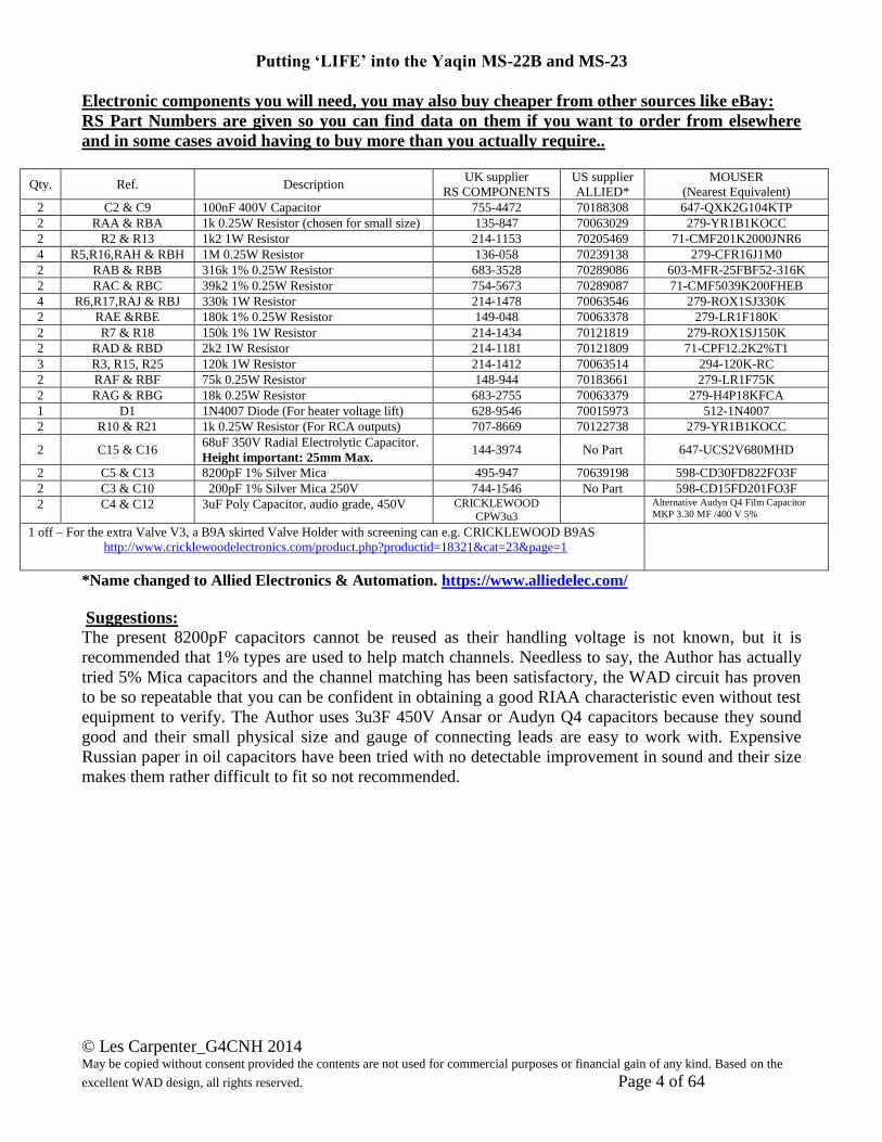
Electronic components you will need, you may also buy cheaper from other sources like eBay:
RS Part Numbers are given so you can find data on them if you want to order from elsewhere
and in some cases avoid having to buy more than you actually require..
Qty. Ref. Description UK supplier
RS COMPONENTS
US supplier
ALLIED*
MOUSER
(Nearest Equivalent)
2 C2 & C9 100nF 400V Capacitor 755-4472 70188308 647-QXK2G104KTP
2 RAA & RBA 1k 0.25W Resistor (chosen for small size) 135-847 70063029 279-YR1B1KOCC
2 R2 & R13 1k2 1W Resistor 214-1153 70205469 71-CMF201K2000JNR6
4 R5,R16,RAH & RBH 1M 0.25W Resistor 136-058 70239138 279-CFR16J1M0
2 RAB & RBB 316k 1% 0.25W Resistor 683-3528 70289086 603-MFR-25FBF52-316K
2 RAC & RBC 39k2 1% 0.25W Resistor 754-5673 70289087 71-CMF5039K200FHEB
4 R6,R17,RAJ & RBJ 330k 1W Resistor 214-1478 70063546 279-ROX1SJ330K
2 RAE &RBE 180k 1% 0.25W Resistor 149-048 70063378 279-LR1F180K
2 R7 & R18 150k 1% 1W Resistor 214-1434 70121819 279-ROX1SJ150K
2 RAD & RBD 2k2 1W Resistor 214-1181 70121809 71-CPF12.2K2%T1
3 R3, R15, R25 120k 1W Resistor 214-1412 70063514 294-120K-RC
2 RAF & RBF 75k 0.25W Resistor 148-944 70183661 279-LR1F75K
2 RAG & RBG 18k 0.25W Resistor 683-2755 70063379 279-H4P18KFCA
1 D1 1N4007 Diode (For heater voltage lift) 628-9546 70015973 512-1N4007
2 R10 & R21 1k 0.25W Resistor (For RCA outputs) 707-8669 70122738 279-YR1B1KOCC
2 C15 & C16 68uF 350V Radial Electrolytic Capacitor.
Height important: 25mm Max. 144-3974 No Part 647-UCS2V680MHD
2 C5 & C13 8200pF 1% Silver Mica 495-947 70639198 598-CD30FD822FO3F
2 C3 & C10 200pF 1% Silver Mica 250V 744-1546 No Part 598-CD15FD201FO3F
2 C4 & C12 3uF Poly Capacitor, audio grade, 450V CRICKLEWOOD
CPW3u3 Alternative Audyn Q4 Film Capacitor
MKP 3.30 MF /400 V 5%
1 off – For the extra Valve V3, a B9A skirted Valve Holder with screening can e.g. CRICKLEWOOD B9AS
http://www.cricklewoodelectronics.com/product.php?productid=18321&cat=23&page=1
*Name changed to Allied Electronics & Automation. https://www.alliedelec.com/
Suggestions:
The present 8200pF capacitors cannot be reused as their handling voltage is not known, but it is
recommended that 1% types are used to help match channels. Needless to say, the Author has actually
tried 5% Mica capacitors and the channel matching has been satisfactory, the WAD circuit has proven
to be so repeatable that you can be confident in obtaining a good RIAA characteristic even without test
equipment to verify. The Author uses 3u3F 450V Ansar or Audyn Q4 capacitors because they sound
good and their small physical size and gauge of connecting leads are easy to work with. Expensive
Russian paper in oil capacitors have been tried with no detectable improvement in sound and their size
makes them rather difficult to fit so not recommended.

Putting ‘LIFE’ into the Yaqin MS-22B and MS-23
© Les Carpenter_G4CNH 2014 May be copied without consent provided the contents are not used for commercial purposes or financial gain of any kind. Based on the
excellent WAD design, all rights reserved. Page 5 of 64
Basically, you will be converting the circuitry from the feedback arrangement used by Yaqin (called a
Yin Yang circuit) to the straight filter technique as shown in block form below.
Whilst you are doing these changes, you will also add a diode to the heater regulator to give the heater
voltage a lift of approximately 0.7V and take it from 11.8V to the more ideal 12.6V.
You will also be doing some changes at the RCA jacks that will remove the hum loop that has given
owners such a headache; of course you may have already done this.
It is the Author’s opinion that any small residual hum that still remains is either due to the magnetic
fields from the mains transformer acting upon the metal parts of the input triodes of each channel. Also
power line frequency vibrations from the transformer cannot be ruled out. Real high end RIAA
amplifiers use a remote power supply to get over such problems, however the level is so small after
converting the MS22/23 that it cannot be heard at normal listening levels on the main amplifier.
IMPORTANT SAFETY NOTE!
PLEASE CHECK THAT THE POWER INPUT IS REMOVED BEFORE STARTING!
AS YOU PROCEED THERE ARE DIFFERENCES BETWEEN THE 22B AND THE 23B
WHICH HAVE TO BE OBSERVED.
Nothing too severe, the circuit is the same; just the mechanics have altered slightly.
MS23B changes will be highlighted in Blue as you go through the conversion.
Putting ‘LIFE’ into the Yaqin MS-22B and MS-23
© Les Carpenter_G4CNH 2014 May be copied without consent provided the contents are not used for commercial purposes or financial gain of any kind. Based on the
excellent WAD design, all rights reserved. Page 6 of 64
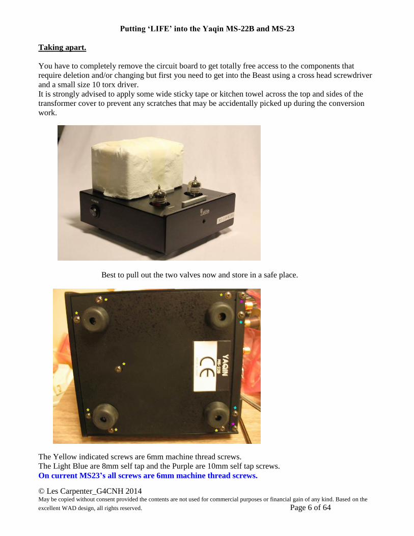
Taking apart.
You have to completely remove the circuit board to get totally free access to the components that
require deletion and/or changing but first you need to get into the Beast using a cross head screwdriver
and a small size 10 torx driver.
It is strongly advised to apply some wide sticky tape or kitchen towel across the top and sides of the
transformer cover to prevent any scratches that may be accidentally picked up during the conversion
work.
Best to pull out the two valves now and store in a safe place.
The Yellow indicated screws are 6mm machine thread screws.
The Light Blue are 8mm self tap and the Purple are 10mm self tap screws.
On current MS23’s all screws are 6mm machine thread screws.
Putting ‘LIFE’ into the Yaqin MS-22B and MS-23
© Les Carpenter_G4CNH 2014 May be copied without consent provided the contents are not used for commercial purposes or financial gain of any kind. Based on the
excellent WAD design, all rights reserved. Page 7 of 64
The cover should now slide slightly towards the front to disengage the rear lip after which the cover
can be lifted away. The Author found this slightly difficult due to a foot screw fouling on the internal
screening frame. In this respect it will be found helpful to also remove the top right hand foot as shown
in the above picture. This is not a problem on MS23’s that use a different type of foot.
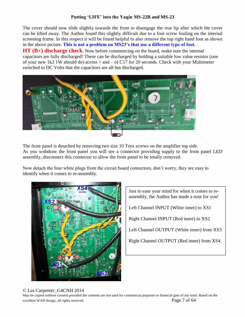
HT (B+) discharge check. Now before commencing on the board, make sure the internal
capacitors are fully discharged! These can be discharged by holding a suitable low value resistor (one
of your new 1k2 1W should do) across + and – of C17 for 20 seconds. Check with your Multimeter
switched to DC Volts that the capacitors are all but discharged.
The front panel is detached by removing two size 10 Torx screws on the amplifier top side.
As you withdraw the front panel you will see a connector providing supply to the front panel LED
assembly, disconnect this connector to allow the front panel to be totally removed.
Now detach the four white plugs from the circuit board connectors, don’t worry, they are easy to
identify when it comes to re-assembly.
Just to ease your mind for when it comes to re-
assembly, the Author has made a note for you!
Left Channel INPUT (White inner) to XS1
Right Channel INPUT (Red inner) to XS2
Left Channel OUTPUT (White inner) from XS3
Right Channel OUTPUT (Red inner) from XS4.
Putting ‘LIFE’ into the Yaqin MS-22B and MS-23
© Les Carpenter_G4CNH 2014 May be copied without consent provided the contents are not used for commercial purposes or financial gain of any kind. Based on the
excellent WAD design, all rights reserved. Page 8 of 64
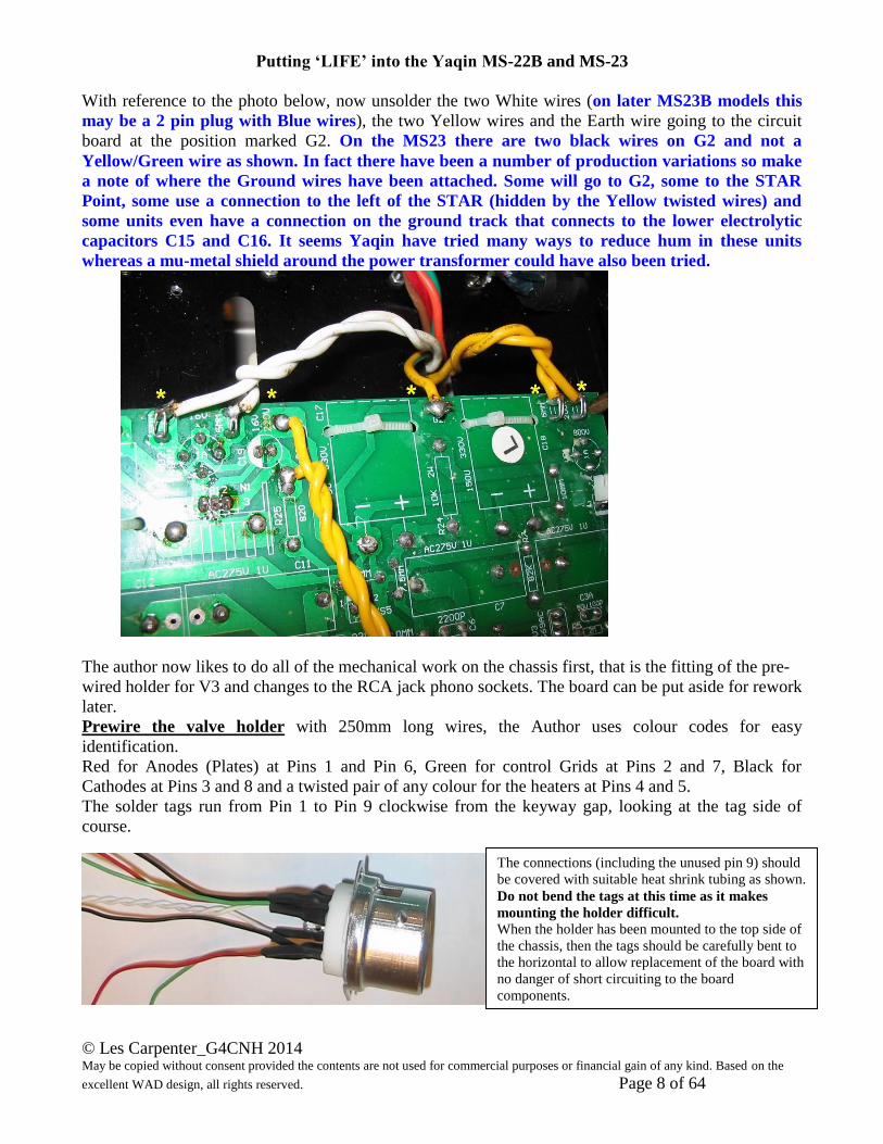
With reference to the photo below, now unsolder the two White wires (on later MS23B models this
may be a 2 pin plug with Blue wires), the two Yellow wires and the Earth wire going to the circuit
board at the position marked G2. On the MS23 there are two black wires on G2 and not a
Yellow/Green wire as shown. In fact there have been a number of production variations so make
a note of where the Ground wires have been attached. Some will go to G2, some to the STAR
Point, some use a connection to the left of the STAR (hidden by the Yellow twisted wires) and
some units even have a connection on the ground track that connects to the lower electrolytic
capacitors C15 and C16. It seems Yaqin have tried many ways to reduce hum in these units
whereas a mu-metal shield around the power transformer could have also been tried.
The author now likes to do all of the mechanical work on the chassis first, that is the fitting of the pre-
wired holder for V3 and changes to the RCA jack phono sockets. The board can be put aside for rework
later.
Prewire the valve holder with 250mm long wires, the Author uses colour codes for easy
identification.
Red for Anodes (Plates) at Pins 1 and Pin 6, Green for control Grids at Pins 2 and 7, Black for
Cathodes at Pins 3 and 8 and a twisted pair of any colour for the heaters at Pins 4 and 5.
The solder tags run from Pin 1 to Pin 9 clockwise from the keyway gap, looking at the tag side of
course.
The connections (including the unused pin 9) should
be covered with suitable heat shrink tubing as shown.
Do not bend the tags at this time as it makes
mounting the holder difficult. When the holder has been mounted to the top side of
the chassis, then the tags should be carefully bent to
the horizontal to allow replacement of the board with
no danger of short circuiting to the board
components.

Putting ‘LIFE’ into the Yaqin MS-22B and MS-23
© Les Carpenter_G4CNH 2014 May be copied without consent provided the contents are not used for commercial purposes or financial gain of any kind. Based on the
excellent WAD design, all rights reserved. Page 9 of 64
We can now turn our attention to the chassis modifications, first look at the following photo.
Remove the two 6mm long size 10 Torx headed screws and the central cross head screw (marked with
asterisks), the latter secures an internal screening frame and may be either threaded or of the self-
tapping variety.

Putting ‘LIFE’ into the Yaqin MS-22B and MS-23
© Les Carpenter_G4CNH 2014 May be copied without consent provided the contents are not used for commercial purposes or financial gain of any kind. Based on the
excellent WAD design, all rights reserved. Page 10 of 64
First step: Hum reduction and checking RCA Ground connections:
Check that the Ground lugs of the RCA sockets are not soldered together, this applies to both the
INPUT and OUTPUT socket pairs.
As shown in the photo, if you find the two Ground tags soldered together then separate the tags and
Black wires. The newer units appear to have some kind of thread locking varnish applied which makes
it difficult to loosen the fixing nut. The author removes both Black wires and excess solder, then
reheats the connection whilst turning one of the RCA jacks with a 15mm socket or combination
wrench. With luck the two tags will separate and you should continue turning until the tags are well
spaced apart. Finally reconnect the respective Black wires to their own independent tags.
If later on, after the conversion, you find you are still suffering from bad hum problems, then trying the
procedures outlined in the following link may solve the problem for you.
http://www.g4cnh.com/public/Special_Grounding_Mod.pdf
Putting ‘LIFE’ into the Yaqin MS-22B and MS-23
© Les Carpenter_G4CNH 2014 May be copied without consent provided the contents are not used for commercial purposes or financial gain of any kind. Based on the
excellent WAD design, all rights reserved. Page 11 of 64
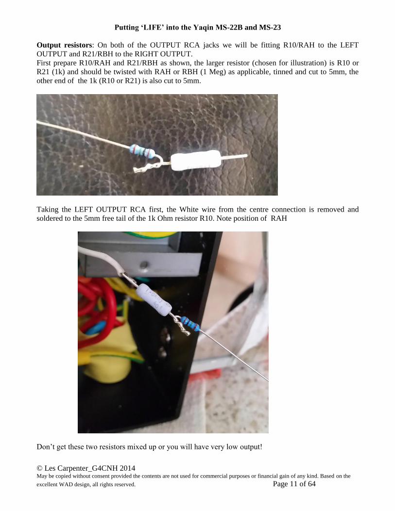
Output resistors: On both of the OUTPUT RCA jacks we will be fitting R10/RAH to the LEFT
OUTPUT and R21/RBH to the RIGHT OUTPUT.
First prepare R10/RAH and R21/RBH as shown, the larger resistor (chosen for illustration) is R10 or
R21 (1k) and should be twisted with RAH or RBH (1 Meg) as applicable, tinned and cut to 5mm, the
other end of the 1k (R10 or R21) is also cut to 5mm.
Taking the LEFT OUTPUT RCA first, the White wire from the centre connection is removed and
soldered to the 5mm free tail of the 1k Ohm resistor R10. Note position of RAH
Don’t get these two resistors mixed up or you will have very low output!
Putting ‘LIFE’ into the Yaqin MS-22B and MS-23
© Les Carpenter_G4CNH 2014 May be copied without consent provided the contents are not used for commercial purposes or financial gain of any kind. Based on the
excellent WAD design, all rights reserved. Page 12 of 64
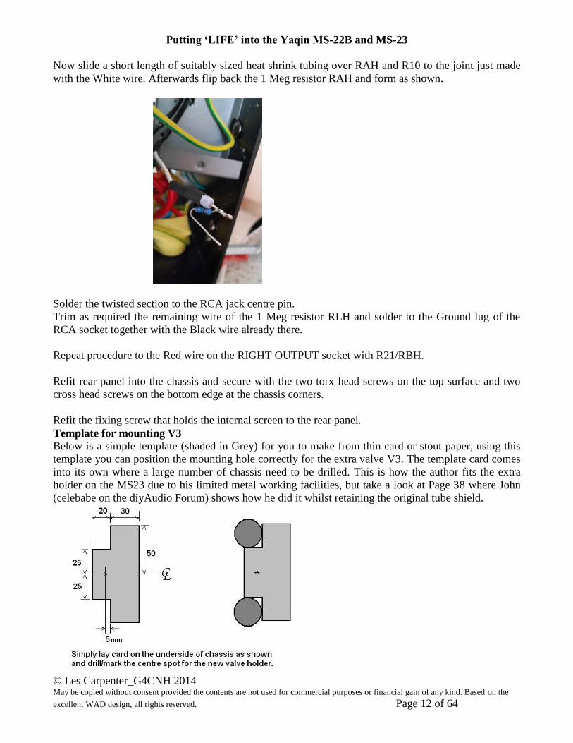
Now slide a short length of suitably sized heat shrink tubing over RAH and R10 to the joint just made
with the White wire. Afterwards flip back the 1 Meg resistor RAH and form as shown.
Solder the twisted section to the RCA jack centre pin.
Trim as required the remaining wire of the 1 Meg resistor RLH and solder to the Ground lug of the
RCA socket together with the Black wire already there.
Repeat procedure to the Red wire on the RIGHT OUTPUT socket with R21/RBH.
Refit rear panel into the chassis and secure with the two torx head screws on the top surface and two
cross head screws on the bottom edge at the chassis corners.
Refit the fixing screw that holds the internal screen to the rear panel.
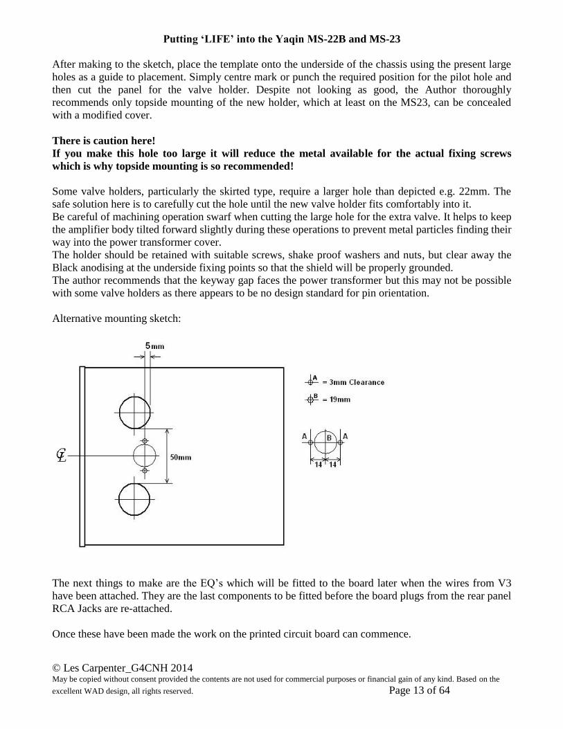
Template for mounting V3
Below is a simple template (shaded in Grey) for you to make from thin card or stout paper, using this
template you can position the mounting hole correctly for the extra valve V3. The template card comes
into its own where a large number of chassis need to be drilled. This is how the author fits the extra
holder on the MS23 due to his limited metal working facilities, but take a look at Page 38 where John
(celebabe on the diyAudio Forum) shows how he did it whilst retaining the original tube shield.
Putting ‘LIFE’ into the Yaqin MS-22B and MS-23
© Les Carpenter_G4CNH 2014 May be copied without consent provided the contents are not used for commercial purposes or financial gain of any kind. Based on the
excellent WAD design, all rights reserved. Page 13 of 64
After making to the sketch, place the template onto the underside of the chassis using the present large
holes as a guide to placement. Simply centre mark or punch the required position for the pilot hole and
then cut the panel for the valve holder. Despite not looking as good, the Author thoroughly
recommends only topside mounting of the new holder, which at least on the MS23, can be concealed
with a modified cover.
There is caution here!
If you make this hole too large it will reduce the metal available for the actual fixing screws
which is why topside mounting is so recommended!
Some valve holders, particularly the skirted type, require a larger hole than depicted e.g. 22mm. The
safe solution here is to carefully cut the hole until the new valve holder fits comfortably into it.
Be careful of machining operation swarf when cutting the large hole for the extra valve. It helps to keep
the amplifier body tilted forward slightly during these operations to prevent metal particles finding their
way into the power transformer cover.
The holder should be retained with suitable screws, shake proof washers and nuts, but clear away the
Black anodising at the underside fixing points so that the shield will be properly grounded.
The author recommends that the keyway gap faces the power transformer but this may not be possible
with some valve holders as there appears to be no design standard for pin orientation.
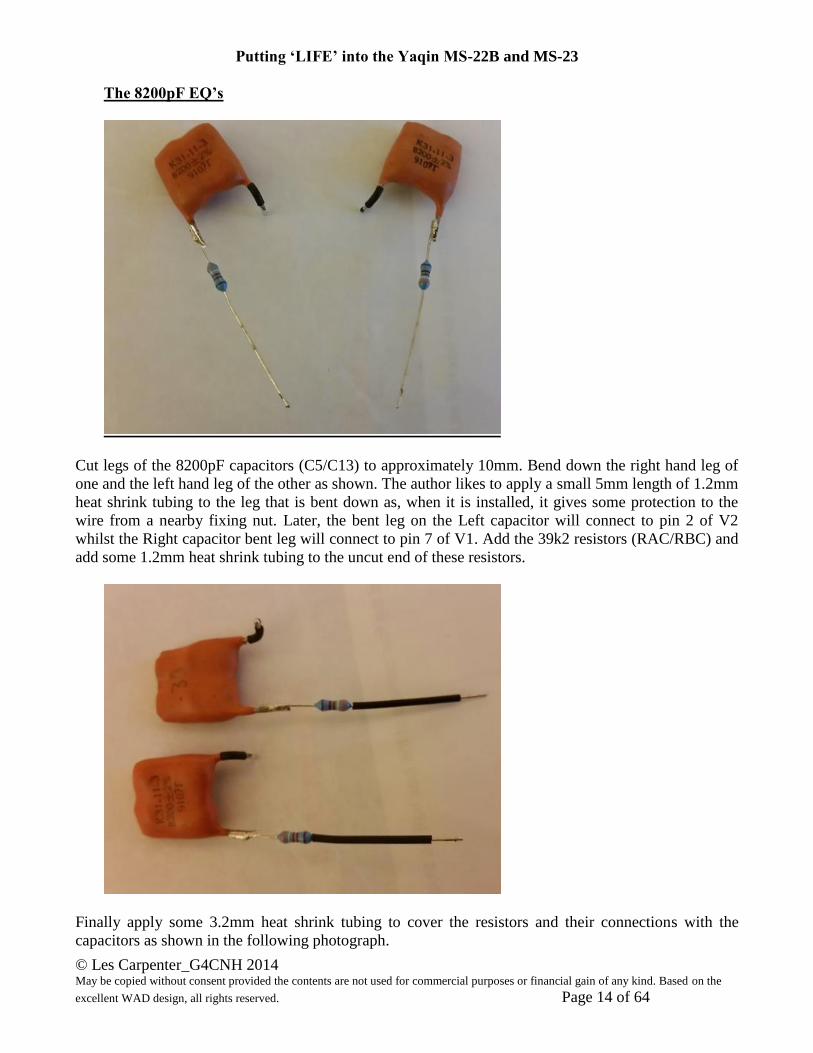
Alternative mounting sketch:
The next things to make are the EQ’s which will be fitted to the board later when the wires from V3
have been attached. They are the last components to be fitted before the board plugs from the rear panel
RCA Jacks are re-attached.
Once these have been made the work on the printed circuit board can commence.
Putting ‘LIFE’ into the Yaqin MS-22B and MS-23
© Les Carpenter_G4CNH 2014 May be copied without consent provided the contents are not used for commercial purposes or financial gain of any kind. Based on the
excellent WAD design, all rights reserved. Page 14 of 64
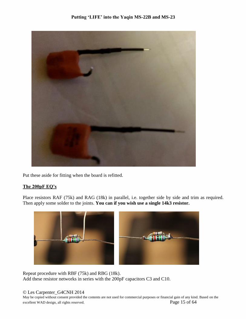
The 8200pF EQ’s
Cut legs of the 8200pF capacitors (C5/C13) to approximately 10mm. Bend down the right hand leg of
one and the left hand leg of the other as shown. The author likes to apply a small 5mm length of 1.2mm
heat shrink tubing to the leg that is bent down as, when it is installed, it gives some protection to the
wire from a nearby fixing nut. Later, the bent leg on the Left capacitor will connect to pin 2 of V2
whilst the Right capacitor bent leg will connect to pin 7 of V1. Add the 39k2 resistors (RAC/RBC) and
add some 1.2mm heat shrink tubing to the uncut end of these resistors.
Finally apply some 3.2mm heat shrink tubing to cover the resistors and their connections with the
capacitors as shown in the following photograph.
Putting ‘LIFE’ into the Yaqin MS-22B and MS-23
© Les Carpenter_G4CNH 2014 May be copied without consent provided the contents are not used for commercial purposes or financial gain of any kind. Based on the
excellent WAD design, all rights reserved. Page 15 of 64
Put these aside for fitting when the board is refitted.
The 200pF EQ’s
Place resistors RAF (75k) and RAG (18k) in parallel, i.e. together side by side and trim as required.
Then apply some solder to the joints. You can if you wish use a single 14k3 resistor.
Repeat procedure with RBF (75k) and RBG (18k).
Add these resistor networks in series with the 200pF capacitors C3 and C10.
Putting ‘LIFE’ into the Yaqin MS-22B and MS-23
© Les Carpenter_G4CNH 2014 May be copied without consent provided the contents are not used for commercial purposes or financial gain of any kind. Based on the
excellent WAD design, all rights reserved. Page 16 of 64
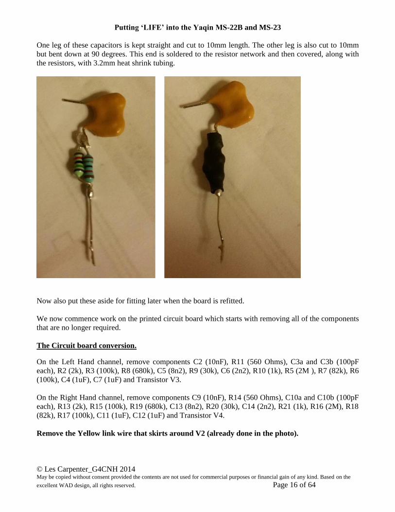
One leg of these capacitors is kept straight and cut to 10mm length. The other leg is also cut to 10mm
but bent down at 90 degrees. This end is soldered to the resistor network and then covered, along with
the resistors, with 3.2mm heat shrink tubing.
Now also put these aside for fitting later when the board is refitted.
We now commence work on the printed circuit board which starts with removing all of the components
that are no longer required.
The Circuit board conversion.
On the Left Hand channel, remove components C2 (10nF), R11 (560 Ohms), C3a and C3b (100pF
each), R2 (2k), R3 (100k), R8 (680k), C5 (8n2), R9 (30k), C6 (2n2), R10 (1k), R5 (2M ), R7 (82k), R6
(100k), C4 (1uF), C7 (1uF) and Transistor V3.
On the Right Hand channel, remove components C9 (10nF), R14 (560 Ohms), C10a and C10b (100pF
each), R13 (2k), R15 (100k), R19 (680k), C13 (8n2), R20 (30k), C14 (2n2), R21 (1k), R16 (2M), R18
(82k), R17 (100k), C11 (1uF), C12 (1uF) and Transistor V4.
Remove the Yellow link wire that skirts around V2 (already done in the photo).
Putting ‘LIFE’ into the Yaqin MS-22B and MS-23
© Les Carpenter_G4CNH 2014 May be copied without consent provided the contents are not used for commercial purposes or financial gain of any kind. Based on the
excellent WAD design, all rights reserved. Page 17 of 64
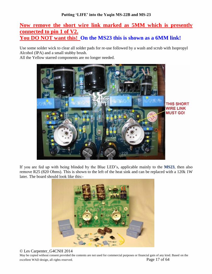
Now remove the short wire link marked as 5MM which is presently
connected to pin 1 of V2.
You DO NOT want this! On the MS23 this is shown as a 6MM link!
Use some solder wick to clear all solder pads for re-use followed by a wash and scrub with Isopropyl
Alcohol (IPA) and a small stubby brush.
All the Yellow starred components are no longer needed.
If you are fed up with being blinded by the Blue LED’s, applicable mainly to the MS23, then also
remove R25 (820 Ohms). This is shown to the left of the heat sink and can be replaced with a 120k 1W
later. The board should look like this:-
Putting ‘LIFE’ into the Yaqin MS-22B and MS-23
© Les Carpenter_G4CNH 2014 May be copied without consent provided the contents are not used for commercial purposes or financial gain of any kind. Based on the
excellent WAD design, all rights reserved. Page 18 of 64
References will still point to the original Yaqin component numbers but where new parts are added, a
letter system is used to avoid any confusion. Component references like RAA, RAB, RAC etc. refer to
the Left Channel whereas their counterparts on the Right channel will be called RBA, RBB, RBC etc.
One thing to remember! When you are working on the printed circuit side of the board, the Left
channel is on the Right Hand side as you look at it! The Author has been caught out a few times by this
Views of the actual circuit boards may differ due to production changes, particularly the change in
Valve Holders and the addition of slots between valve pins on later models.
Some of the photos were taken at advanced stages to what is being described so ignore other
components that are not applicable to the work in hand.
The procedure for track cutting, drilling and component placement has been changed from previous
issues, all the cutting, drilling and component placement is all done in 3 set stages, i.e. all cleaning,
cutting then drilling. This is how the author now does the board rework as he found it better to
complete each stage whilst tooling was to hand.
Preparation before Track Cutting and Drilling -
a) De-solder pin 2 and pin 6 of V1.
b) De-solder pin 1 and pin 2 of V2
c) Remove all 3mm nuts and fibre washers from the valve holders.
1. CLEANING AWAY GREEN SOLDER RESIST.
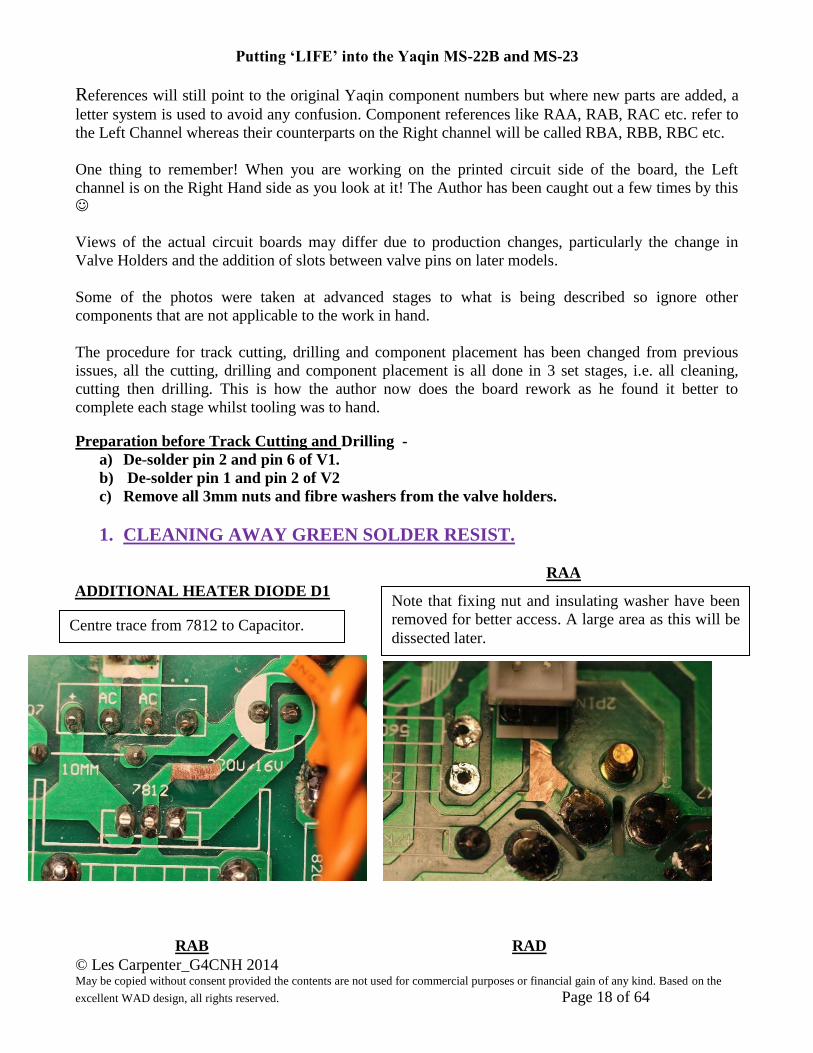
RAA
ADDITIONAL HEATER DIODE D1
RAB RAD
Centre trace from 7812 to Capacitor.
Note that fixing nut and insulating washer have been
removed for better access. A large area as this will be
dissected later.
Putting ‘LIFE’ into the Yaqin MS-22B and MS-23
© Les Carpenter_G4CNH 2014 May be copied without consent provided the contents are not used for commercial purposes or financial gain of any kind. Based on the
excellent WAD design, all rights reserved. Page 19 of 64
RAE RBA
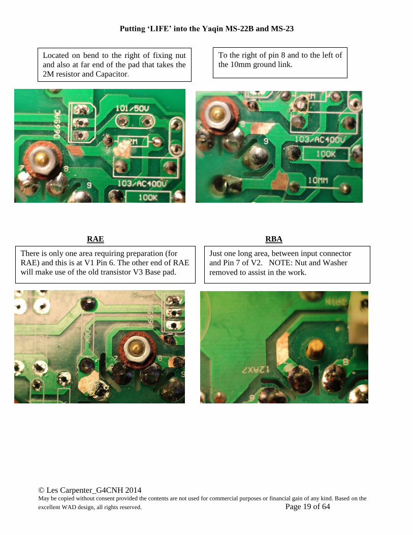
To the right of pin 8 and to the left of
the 10mm ground link.
Located on bend to the right of fixing nut
and also at far end of the pad that takes the
2M resistor and Capacitor.
There is only one area requiring preparation (for
RAE) and this is at V1 Pin 6. The other end of RAE
will make use of the old transistor V3 Base pad.
Just one long area, between input connector
and Pin 7 of V2. NOTE: Nut and Washer
removed to assist in the work.
Putting ‘LIFE’ into the Yaqin MS-22B and MS-23
© Les Carpenter_G4CNH 2014 May be copied without consent provided the contents are not used for commercial purposes or financial gain of any kind. Based on the
excellent WAD design, all rights reserved. Page 20 of 64
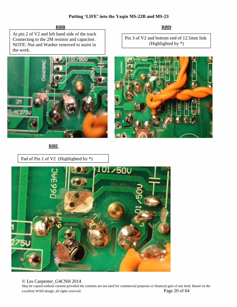
RBB RBD
RBE
At pin 2 of V2 and left hand side of the track
Connecting to the 2M resistor and capacitor.
NOTE: Nut and Washer removed to assist in
the work.
Pin 3 of V2 and bottom end of 12.5mm link
(Highlighted by *)
Pad of Pin 1 of V2 (Highlighted by *)
Putting ‘LIFE’ into the Yaqin MS-22B and MS-23
© Les Carpenter_G4CNH 2014 May be copied without consent provided the contents are not used for commercial purposes or financial gain of any kind. Based on the
excellent WAD design, all rights reserved. Page 21 of 64
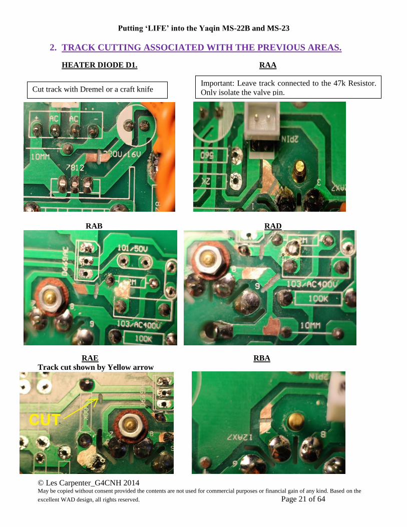
2. TRACK CUTTING ASSOCIATED WITH THE PREVIOUS AREAS.
HEATER DIODE D1. RAA
RAB RAD
RAE RBA
Track cut shown by Yellow arrow
Cut track with Dremel or a craft knife
Important: Leave track connected to the 47k Resistor.
Only isolate the valve pin.
Putting ‘LIFE’ into the Yaqin MS-22B and MS-23
© Les Carpenter_G4CNH 2014 May be copied without consent provided the contents are not used for commercial purposes or financial gain of any kind. Based on the
excellent WAD design, all rights reserved. Page 22 of 64
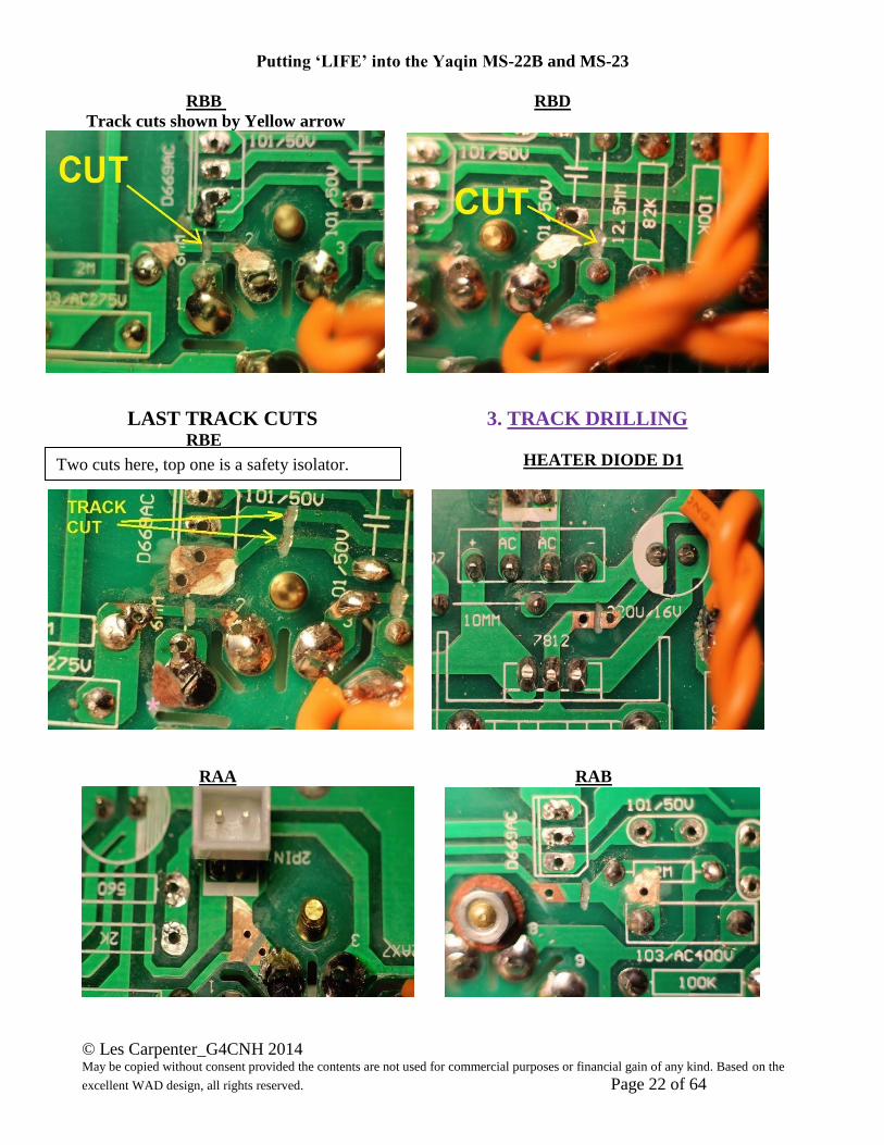
RBB RBD
Track cuts shown by Yellow arrow
LAST TRACK CUTS 3. TRACK DRILLING RBE
HEATER DIODE D1
RAA RAB
Two cuts here, top one is a safety isolator.

Putting ‘LIFE’ into the Yaqin MS-22B and MS-23
© Les Carpenter_G4CNH 2014 May be copied without consent provided the contents are not used for commercial purposes or financial gain of any kind. Based on the
excellent WAD design, all rights reserved. Page 23 of 64
RAE
RAD
RBA RBB
RBD RBE
Only one area requiring drilling and this
is at V1 Pin 6.
Pin 3 of V2 and bottom end of 12.5mm link
Pin 1 of V2
Putting ‘LIFE’ into the Yaqin MS-22B and MS-23
© Les Carpenter_G4CNH 2014 May be copied without consent provided the contents are not used for commercial purposes or financial gain of any kind. Based on the
excellent WAD design, all rights reserved. Page 24 of 64
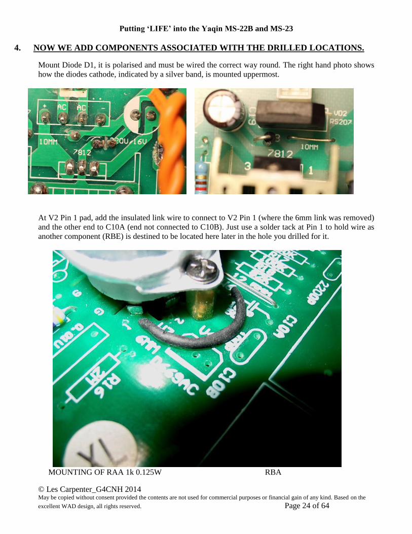
4. NOW WE ADD COMPONENTS ASSOCIATED WITH THE DRILLED LOCATIONS.
Mount Diode D1, it is polarised and must be wired the correct way round. The right hand photo shows
how the diodes cathode, indicated by a silver band, is mounted uppermost.
At V2 Pin 1 pad, add the insulated link wire to connect to V2 Pin 1 (where the 6mm link was removed)
and the other end to C10A (end not connected to C10B). Just use a solder tack at Pin 1 to hold wire as
another component (RBE) is destined to be located here later in the hole you drilled for it.
MOUNTING OF RAA 1k 0.125W RBA
Putting ‘LIFE’ into the Yaqin MS-22B and MS-23
© Les Carpenter_G4CNH 2014 May be copied without consent provided the contents are not used for commercial purposes or financial gain of any kind. Based on the
excellent WAD design, all rights reserved. Page 25 of 64
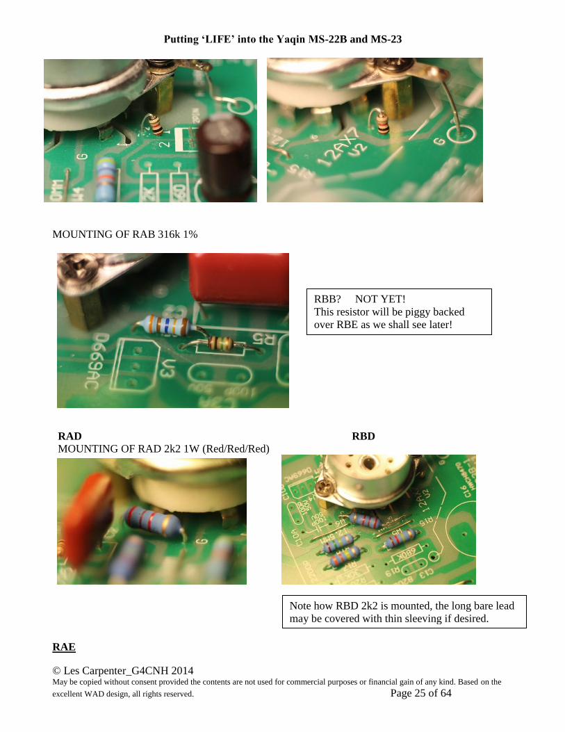
MOUNTING OF RAB 316k 1%
RAD RBD
MOUNTING OF RAD 2k2 1W (Red/Red/Red)
RAE
RBB? NOT YET!
This resistor will be piggy backed
over RBE as we shall see later!
Note how RBD 2k2 is mounted, the long bare lead
may be covered with thin sleeving if desired.
Putting ‘LIFE’ into the Yaqin MS-22B and MS-23
© Les Carpenter_G4CNH 2014 May be copied without consent provided the contents are not used for commercial purposes or financial gain of any kind. Based on the
excellent WAD design, all rights reserved. Page 26 of 64
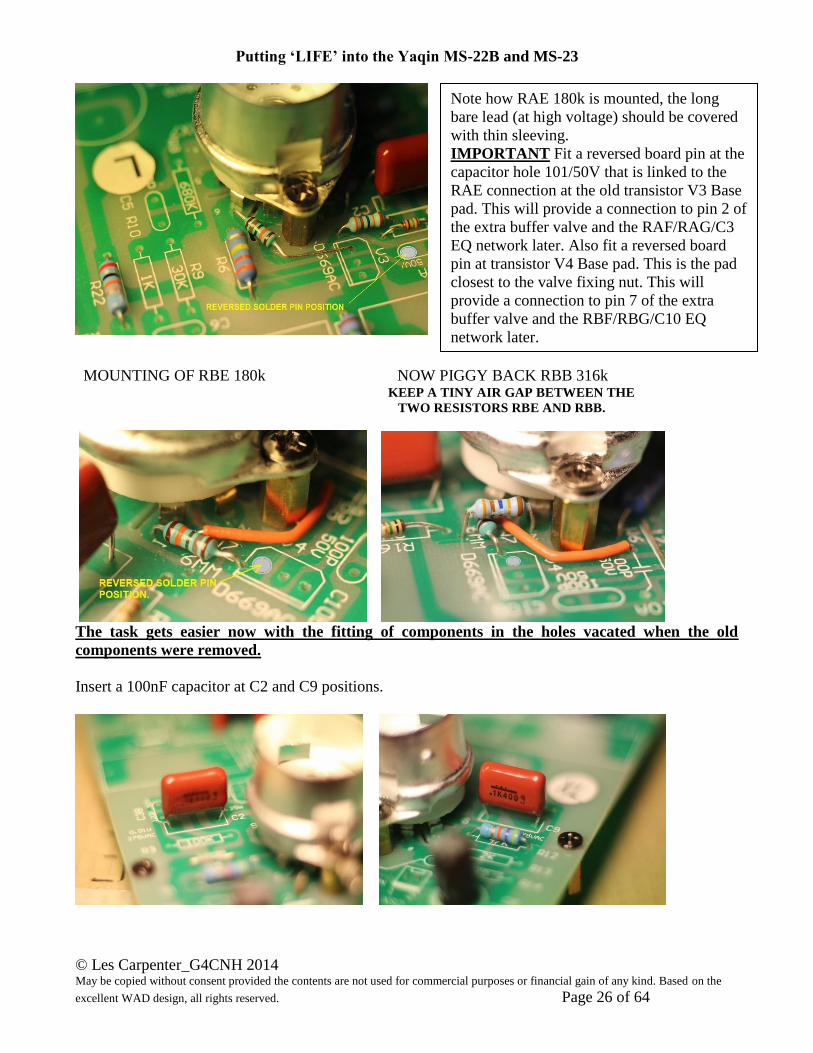
MOUNTING OF RBE 180k NOW PIGGY BACK RBB 316k KEEP A TINY AIR GAP BETWEEN THE
TWO RESISTORS RBE AND RBB.
The task gets easier now with the fitting of components in the holes vacated when the old
components were removed.
Insert a 100nF capacitor at C2 and C9 positions.
Note how RAE 180k is mounted, the long
bare lead (at high voltage) should be covered
with thin sleeving.
IMPORTANT Fit a reversed board pin at the
capacitor hole 101/50V that is linked to the
RAE connection at the old transistor V3 Base
pad. This will provide a connection to pin 2 of
the extra buffer valve and the RAF/RAG/C3
EQ network later. Also fit a reversed board
pin at transistor V4 Base pad. This is the pad
closest to the valve fixing nut. This will
provide a connection to pin 7 of the extra
buffer valve and the RBF/RBG/C10 EQ
network later.

Putting ‘LIFE’ into the Yaqin MS-22B and MS-23
© Les Carpenter_G4CNH 2014 May be copied without consent provided the contents are not used for commercial purposes or financial gain of any kind. Based on the
excellent WAD design, all rights reserved. Page 27 of 64
Insert a 1M Resistor at R5 and R16 positions.
Insert a 330k Ohm 1W resistor at R6 and R17 positions.
Insert a 120k Ohm 1W resistor at R3 and R15 positions.
Insert a 150k Ohm 1W resistor at R7 and R18 positions.
Putting ‘LIFE’ into the Yaqin MS-22B and MS-23
© Les Carpenter_G4CNH 2014 May be copied without consent provided the contents are not used for commercial purposes or financial gain of any kind. Based on the
excellent WAD design, all rights reserved. Page 28 of 64
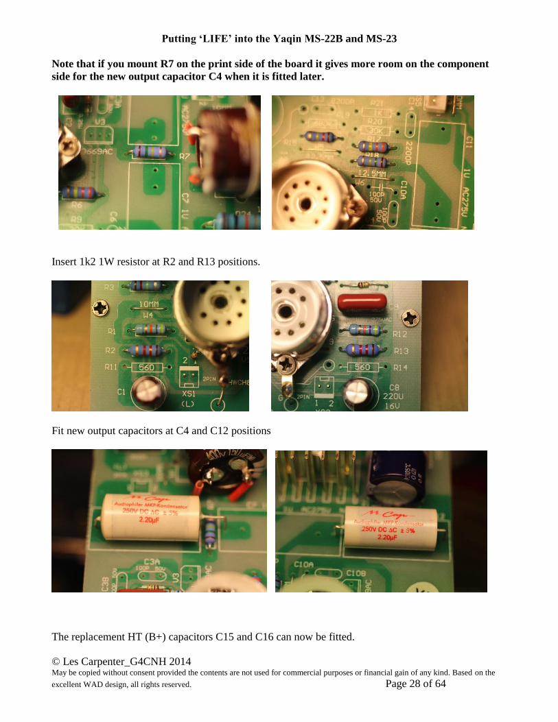
Note that if you mount R7 on the print side of the board it gives more room on the component
side for the new output capacitor C4 when it is fitted later.
Insert 1k2 1W resistor at R2 and R13 positions.
Fit new output capacitors at C4 and C12 positions
The replacement HT (B+) capacitors C15 and C16 can now be fitted.

Putting ‘LIFE’ into the Yaqin MS-22B and MS-23
© Les Carpenter_G4CNH 2014 May be copied without consent provided the contents are not used for commercial purposes or financial gain of any kind. Based on the
excellent WAD design, all rights reserved. Page 29 of 64
Make sure you have the correct 25mm maximum height capacitor types and that these are mounted the
right way round with their negative tags towards the front edge of the board.
Note: Due to supply problems, the 100uF capacitors have now been replaced with 68uF 350V types.
As a safety precaution, add RAJ and RBJ across the pins of each capacitor. These 330k resistors will
ensure that any residual charge on the capacitors is drained after a few minutes yet there value will not
add any appreciable loading to the HT (B+) line.
Now for those wishing to reduce the almost eye damaging glow of the front panel Blue LED’s, here is
the answer. Replace R25 with a 120k 1W resistor, the author has a surplus of 100k 1W resistors which
he uses for this task.
That’s it! Make sure that you have replaced the 3mm nuts and washers removed earlier.
You can now drill the board with 3mm holes to take the wires for the extra valve, use a 4mm for its
heater wires.
The photographs on the next page shows the locations. Carefully feed the wires through these holes
from the component side and if you colour coded the wires then this should be easy to do.
Once the board is in position and the wires pulled through then they can be terminated as required.
Remember to push back the tags of the third valve V3, this will allow the board to be slid back into
place. It is OK to flex the board slightly to get the large capacitors on the front of the board to pass by
the valve. Slowly take up the slack in the wires from V3 as the board goes in, the most frequent
obstruction is the heat sink so check that the wires are not snagged on it.

Putting ‘LIFE’ into the Yaqin MS-22B and MS-23
© Les Carpenter_G4CNH 2014 May be copied without consent provided the contents are not used for commercial purposes or financial gain of any kind. Based on the
excellent WAD design, all rights reserved. Page 30 of 64
Below is an early photograph; the Red Anode wires should now be fed through holes further up the board to
connect with the 10mm link solder pads feeding R22 and R23 (see above and next page).
Putting ‘LIFE’ into the Yaqin MS-22B and MS-23
© Les Carpenter_G4CNH 2014 May be copied without consent provided the contents are not used for commercial purposes or financial gain of any kind. Based on the
excellent WAD design, all rights reserved. Page 31 of 64
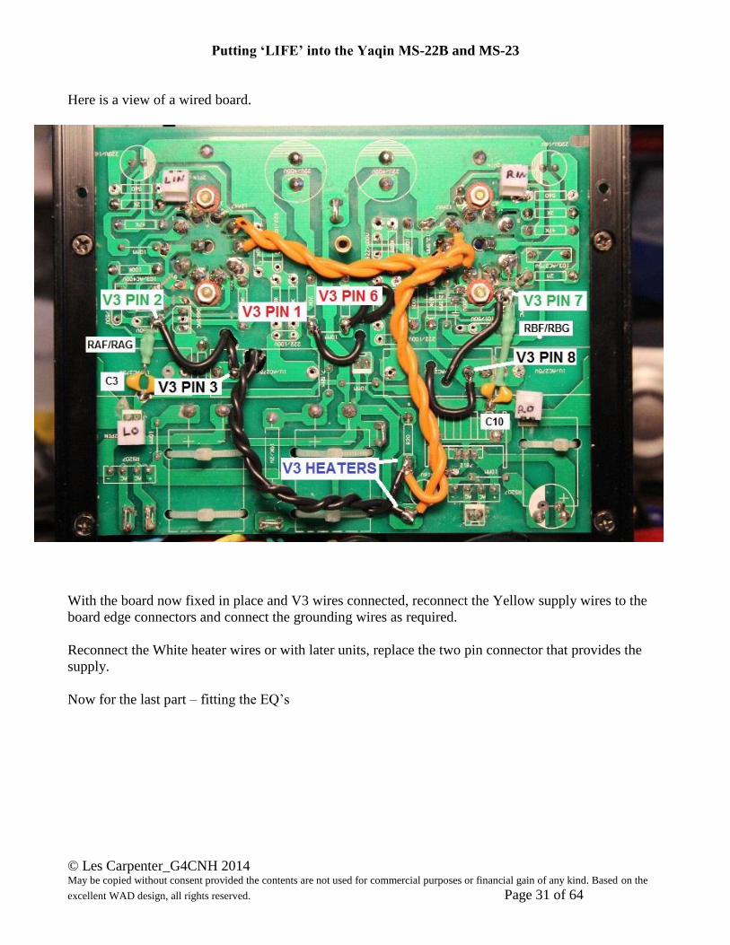
Here is a view of a wired board.
With the board now fixed in place and V3 wires connected, reconnect the Yellow supply wires to the
board edge connectors and connect the grounding wires as required.
Reconnect the White heater wires or with later units, replace the two pin connector that provides the
supply.
Now for the last part – fitting the EQ’s

Putting ‘LIFE’ into the Yaqin MS-22B and MS-23
© Les Carpenter_G4CNH 2014 May be copied without consent provided the contents are not used for commercial purposes or financial gain of any kind. Based on the
excellent WAD design, all rights reserved. Page 32 of 64
Fitting the EQ’s (See also lower picture “Positions of EQ connections favoured by the Author”).
IMPORTANT! Despite being covered in heat shrinkable sleeving, leave a tiny gap between the resistors RAF/RAG
and RBF/RBG as the tracks that lie beneath them carry full HT (B+) voltage.
Positions of EQ connections favoured by the Author.
Putting ‘LIFE’ into the Yaqin MS-22B and MS-23
© Les Carpenter_G4CNH 2014 May be copied without consent provided the contents are not used for commercial purposes or financial gain of any kind. Based on the
excellent WAD design, all rights reserved. Page 33 of 64
You can now connect the four plugs to the board and temporarily replace the bottom cover with just
two holding screws. If you have a digital Multimeter to hand, then it is a good idea to do some ‘cold’
checks on the circuitry before powering up. Temporarily fitting the bottom cover will save you undoing
all of those screws should you find anything wrong?
Just a reminder - valve pins are numbered 1 to 9 clockwise looking from UNDERNEATH. If you are
looking INTO the socket where the valve actually goes, then you have to count the pins in an anti-
clockwise direction, pin 1 in this case being the first pin after the gap.
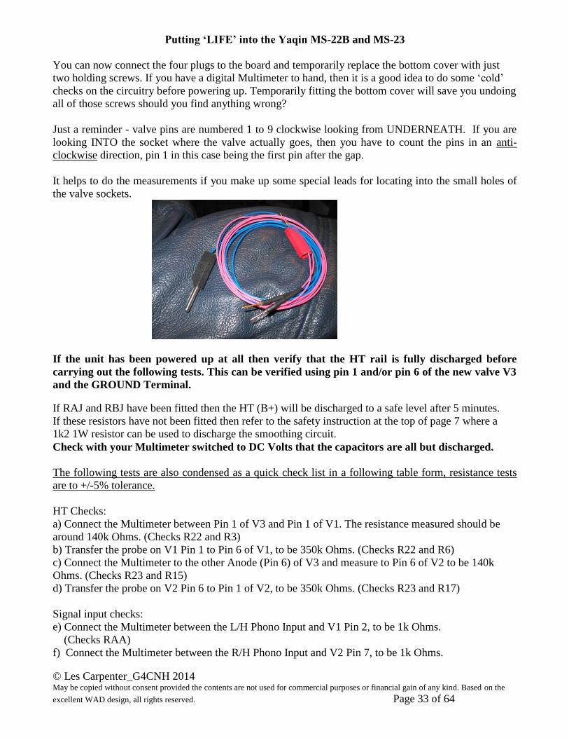
It helps to do the measurements if you make up some special leads for locating into the small holes of
the valve sockets.
If the unit has been powered up at all then verify that the HT rail is fully discharged before
carrying out the following tests. This can be verified using pin 1 and/or pin 6 of the new valve V3
and the GROUND Terminal.
If RAJ and RBJ have been fitted then the HT (B+) will be discharged to a safe level after 5 minutes.
If these resistors have not been fitted then refer to the safety instruction at the top of page 7 where a
1k2 1W resistor can be used to discharge the smoothing circuit.
Check with your Multimeter switched to DC Volts that the capacitors are all but discharged.
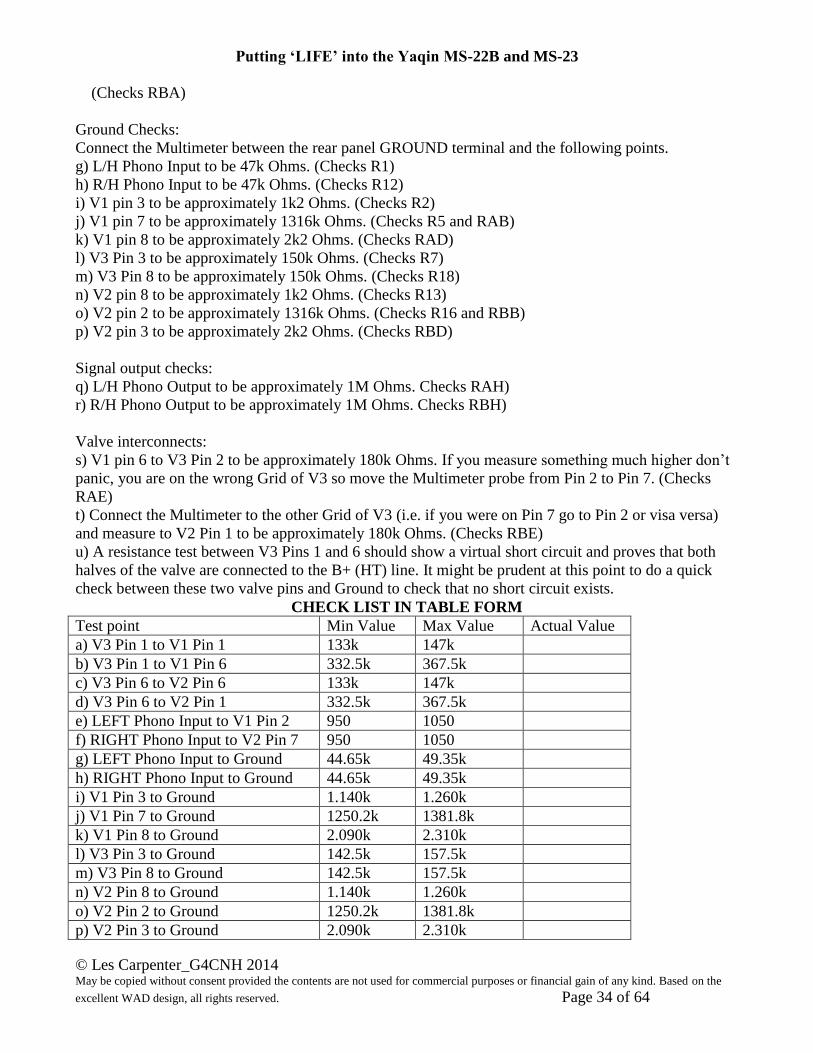
The following tests are also condensed as a quick check list in a following table form, resistance tests
are to +/-5% tolerance.
HT Checks:
a) Connect the Multimeter between Pin 1 of V3 and Pin 1 of V1. The resistance measured should be
around 140k Ohms. (Checks R22 and R3)
b) Transfer the probe on V1 Pin 1 to Pin 6 of V1, to be 350k Ohms. (Checks R22 and R6)
c) Connect the Multimeter to the other Anode (Pin 6) of V3 and measure to Pin 6 of V2 to be 140k
Ohms. (Checks R23 and R15)
d) Transfer the probe on V2 Pin 6 to Pin 1 of V2, to be 350k Ohms. (Checks R23 and R17)
Signal input checks:
e) Connect the Multimeter between the L/H Phono Input and V1 Pin 2, to be 1k Ohms.
(Checks RAA)
f) Connect the Multimeter between the R/H Phono Input and V2 Pin 7, to be 1k Ohms.
Putting ‘LIFE’ into the Yaqin MS-22B and MS-23
© Les Carpenter_G4CNH 2014 May be copied without consent provided the contents are not used for commercial purposes or financial gain of any kind. Based on the
excellent WAD design, all rights reserved. Page 34 of 64
(Checks RBA)
Ground Checks:
Connect the Multimeter between the rear panel GROUND terminal and the following points.
g) L/H Phono Input to be 47k Ohms. (Checks R1)
h) R/H Phono Input to be 47k Ohms. (Checks R12)
i) V1 pin 3 to be approximately 1k2 Ohms. (Checks R2)
j) V1 pin 7 to be approximately 1316k Ohms. (Checks R5 and RAB)
k) V1 pin 8 to be approximately 2k2 Ohms. (Checks RAD)
l) V3 Pin 3 to be approximately 150k Ohms. (Checks R7)
m) V3 Pin 8 to be approximately 150k Ohms. (Checks R18)
n) V2 pin 8 to be approximately 1k2 Ohms. (Checks R13)
o) V2 pin 2 to be approximately 1316k Ohms. (Checks R16 and RBB)
p) V2 pin 3 to be approximately 2k2 Ohms. (Checks RBD)
Signal output checks:
q) L/H Phono Output to be approximately 1M Ohms. Checks RAH)
r) R/H Phono Output to be approximately 1M Ohms. Checks RBH)
Valve interconnects:
s) V1 pin 6 to V3 Pin 2 to be approximately 180k Ohms. If you measure something much higher don’t
panic, you are on the wrong Grid of V3 so move the Multimeter probe from Pin 2 to Pin 7. (Checks
RAE)
t) Connect the Multimeter to the other Grid of V3 (i.e. if you were on Pin 7 go to Pin 2 or visa versa)
and measure to V2 Pin 1 to be approximately 180k Ohms. (Checks RBE)
u) A resistance test between V3 Pins 1 and 6 should show a virtual short circuit and proves that both
halves of the valve are connected to the B+ (HT) line. It might be prudent at this point to do a quick
check between these two valve pins and Ground to check that no short circuit exists.
CHECK LIST IN TABLE FORM
Test point Min Value Max Value Actual Value
a) V3 Pin 1 to V1 Pin 1 133k 147k
b) V3 Pin 1 to V1 Pin 6 332.5k 367.5k
c) V3 Pin 6 to V2 Pin 6 133k 147k
d) V3 Pin 6 to V2 Pin 1 332.5k 367.5k
e) LEFT Phono Input to V1 Pin 2 950 1050
f) RIGHT Phono Input to V2 Pin 7 950 1050
g) LEFT Phono Input to Ground 44.65k 49.35k
h) RIGHT Phono Input to Ground 44.65k 49.35k
i) V1 Pin 3 to Ground 1.140k 1.260k
j) V1 Pin 7 to Ground 1250.2k 1381.8k
k) V1 Pin 8 to Ground 2.090k 2.310k
l) V3 Pin 3 to Ground 142.5k 157.5k
m) V3 Pin 8 to Ground 142.5k 157.5k
n) V2 Pin 8 to Ground 1.140k 1.260k
o) V2 Pin 2 to Ground 1250.2k 1381.8k
p) V2 Pin 3 to Ground 2.090k 2.310k
Putting ‘LIFE’ into the Yaqin MS-22B and MS-23
© Les Carpenter_G4CNH 2014 May be copied without consent provided the contents are not used for commercial purposes or financial gain of any kind. Based on the
excellent WAD design, all rights reserved. Page 35 of 64
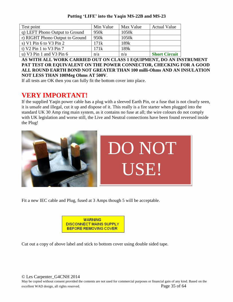
Test point Min Value Max Value Actual Value
q) LEFT Phono Output to Ground 950k 1050k
r) RIGHT Phono Output to Ground 950k 1050k
s) V1 Pin 6 to V3 Pin 2 171k 189k
t) V2 Pin 1 to V3 Pin 7 171k 189k
u) V3 Pin 1 and V3 Pin 6 n/a n/a Short Circuit
AS WITH ALL WORK CARRIED OUT ON CLASS 1 EQUIPMENT, DO AN INSTRUMENT
PAT TEST OR EQUIVALENT ON THE POWER CONNECTOR, CHECKING FOR A GOOD
ALL ROUND EARTH BOND NOT GREATER THAN 100 milli-Ohms AND AN INSULATION
NOT LESS THAN 100Meg Ohms AT 500V.
If all tests are OK then you can fully fit the bottom cover into place.
VERY IMPORTANT! If the supplied Yaqin power cable has a plug with a sleeved Earth Pin, or a fuse that is not clearly seen,
it is unsafe and illegal, cut it up and dispose of it. This really is a fire starter when plugged into the
standard UK 30 Amp ring main system, as it contains no fuse at all; the wire colours do not comply
with UK legislation and worse still, the Live and Neutral connections have been found reversed inside
the Plug!
Fit a new IEC cable and Plug, fused at 3 Amps though 5 will be acceptable.
Cut out a copy of above label and stick to bottom cover using double sided tape.
DO NOT
USE!
Putting ‘LIFE’ into the Yaqin MS-22B and MS-23
© Les Carpenter_G4CNH 2014 May be copied without consent provided the contents are not used for commercial purposes or financial gain of any kind. Based on the
excellent WAD design, all rights reserved. Page 36 of 64
So is there anything we can do with the original MSS23B valve cover that is now ready for the scrap
bin? Yes there is! Read on.
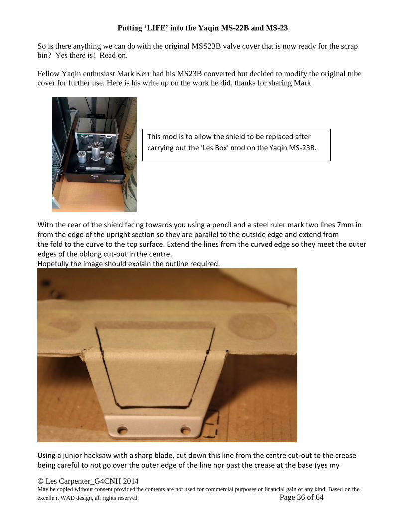
Fellow Yaqin enthusiast Mark Kerr had his MS23B converted but decided to modify the original tube
cover for further use. Here is his write up on the work he did, thanks for sharing Mark.
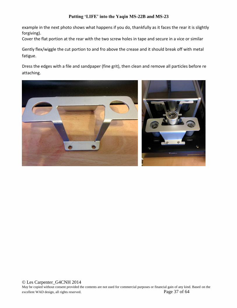
With the rear of the shield facing towards you using a pencil and a steel ruler mark two lines 7mm in from the edge of the upright section so they are parallel to the outside edge and extend from the fold to the curve to the top surface. Extend the lines from the curved edge so they meet the outer edges of the oblong cut-out in the centre. Hopefully the image should explain the outline required.
Using a junior hacksaw with a sharp blade, cut down this line from the centre cut-out to the crease being careful to not go over the outer edge of the line nor past the crease at the base (yes my
This mod is to allow the shield to be replaced after
carrying out the 'Les Box' mod on the Yaqin MS-23B.
Putting ‘LIFE’ into the Yaqin MS-22B and MS-23
© Les Carpenter_G4CNH 2014 May be copied without consent provided the contents are not used for commercial purposes or financial gain of any kind. Based on the
excellent WAD design, all rights reserved. Page 37 of 64
example in the next photo shows what happens if you do, thankfully as it faces the rear it is slightly forgiving). Cover the flat portion at the rear with the two screw holes in tape and secure in a vice or similar
Gently flex/wiggle the cut portion to and fro above the crease and it should break off with metal
fatigue.
Dress the edges with a file and sandpaper (fine grit), then clean and remove all particles before re
attaching.
Putting ‘LIFE’ into the Yaqin MS-22B and MS-23
© Les Carpenter_G4CNH 2014 May be copied without consent provided the contents are not used for commercial purposes or financial gain of any kind. Based on the
excellent WAD design, all rights reserved. Page 38 of 64
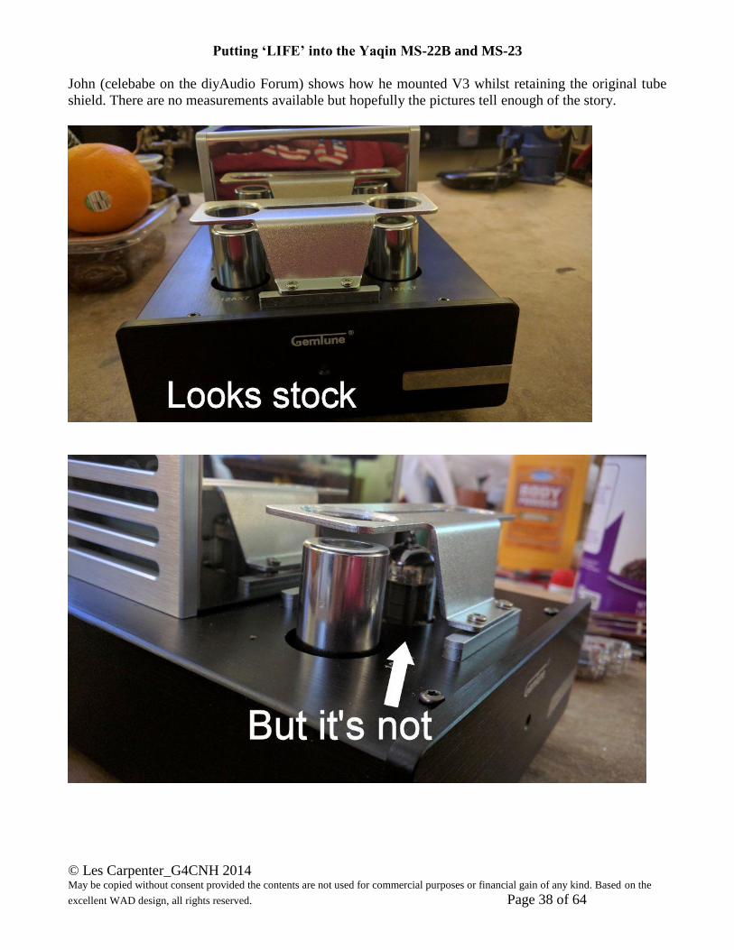
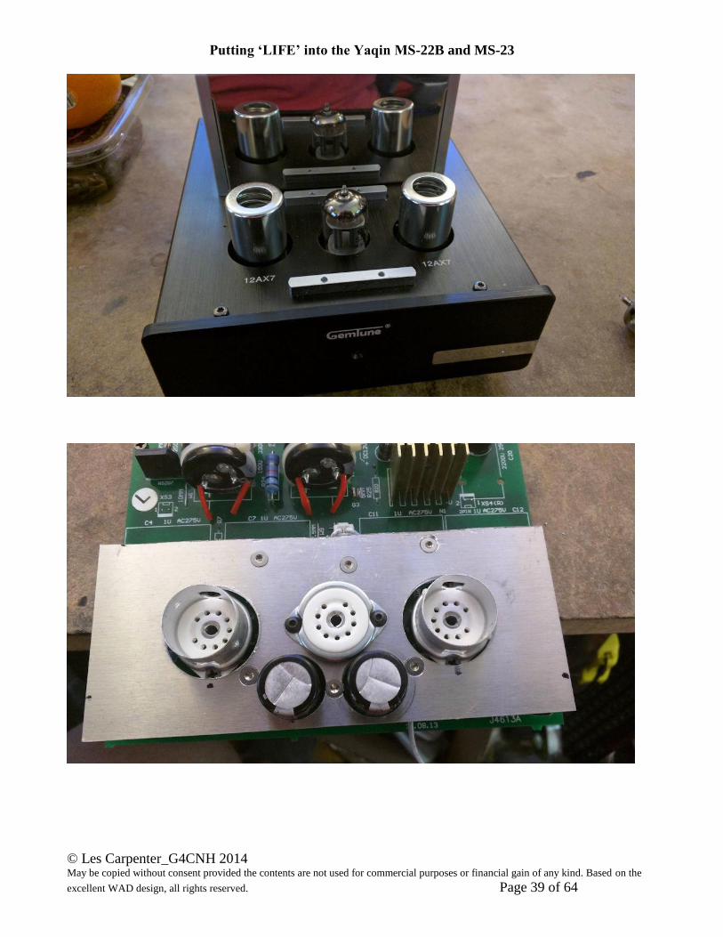
John (celebabe on the diyAudio Forum) shows how he mounted V3 whilst retaining the original tube
shield. There are no measurements available but hopefully the pictures tell enough of the story.
Putting ‘LIFE’ into the Yaqin MS-22B and MS-23
© Les Carpenter_G4CNH 2014 May be copied without consent provided the contents are not used for commercial purposes or financial gain of any kind. Based on the
excellent WAD design, all rights reserved. Page 39 of 64
Putting ‘LIFE’ into the Yaqin MS-22B and MS-23
© Les Carpenter_G4CNH 2014 May be copied without consent provided the contents are not used for commercial purposes or financial gain of any kind. Based on the
excellent WAD design, all rights reserved. Page 40 of 64
Putting ‘LIFE’ into the Yaqin MS-22B and MS-23
© Les Carpenter_G4CNH 2014 May be copied without consent provided the contents are not used for commercial purposes or financial gain of any kind. Based on the
excellent WAD design, all rights reserved. Page 41 of 64
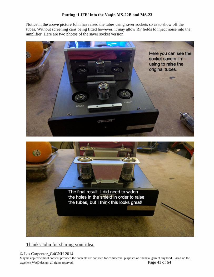
Notice in the above picture John has raised the tubes using saver sockets so as to show off the
tubes. Without screening cans being fitted however, it may allow RF fields to inject noise into the
amplifier. Here are two photos of the saver socket version.
Thanks John for sharing your idea.

Putting ‘LIFE’ into the Yaqin MS-22B and MS-23
© Les Carpenter_G4CNH 2014 May be copied without consent provided the contents are not used for commercial purposes or financial gain of any kind. Based on the
excellent WAD design, all rights reserved. Page 42 of 64
Here is a fully converted MS23B photo from Juha Järvelä
And that’s it apart from a good session with your
favourite vinyl to discover the magic that is now there!
Happy Listening…. Lez at ntlworld dot com
Putting ‘LIFE’ into the Yaqin MS-22B and MS-23
© Les Carpenter_G4CNH 2014 May be copied without consent provided the contents are not used for commercial purposes or financial gain of any kind. Based on the
excellent WAD design, all rights reserved. Page 43 of 64
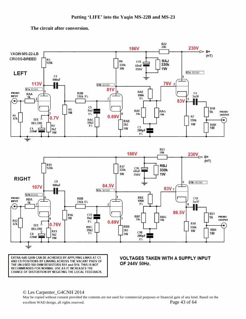
The circuit after conversion.
Putting ‘LIFE’ into the Yaqin MS-22B and MS-23
© Les Carpenter_G4CNH 2014 May be copied without consent provided the contents are not used for commercial purposes or financial gain of any kind. Based on the
excellent WAD design, all rights reserved. Page 44 of 64
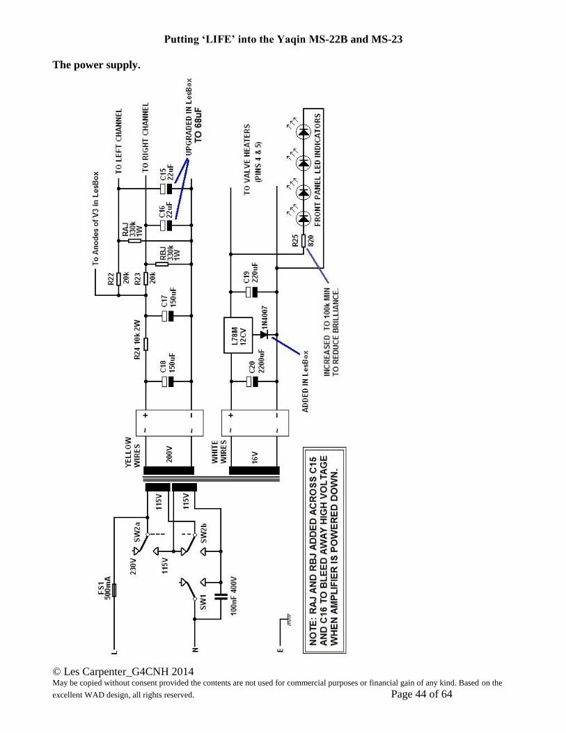
The power supply.
Putting ‘LIFE’ into the Yaqin MS-22B and MS-23
© Les Carpenter_G4CNH 2014 May be copied without consent provided the contents are not used for commercial purposes or financial gain of any kind. Based on the
excellent WAD design, all rights reserved. Page 45 of 64
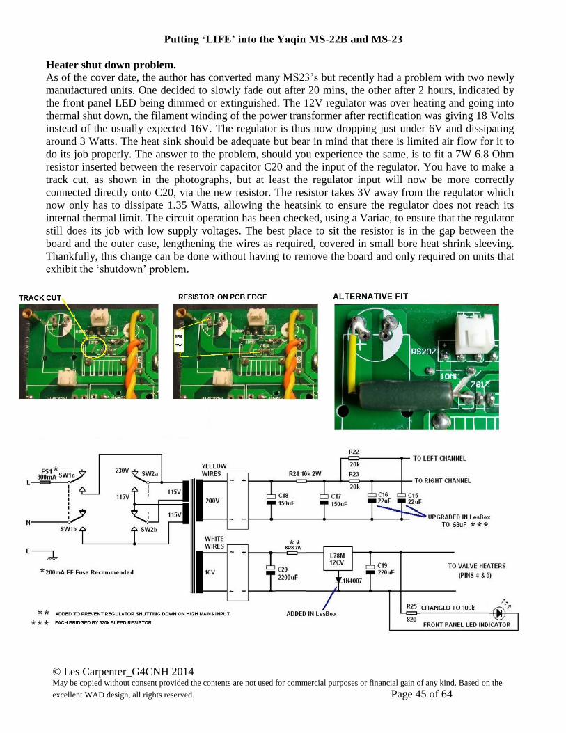
Heater shut down problem.
As of the cover date, the author has converted many MS23’s but recently had a problem with two newly
manufactured units. One decided to slowly fade out after 20 mins, the other after 2 hours, indicated by
the front panel LED being dimmed or extinguished. The 12V regulator was over heating and going into
thermal shut down, the filament winding of the power transformer after rectification was giving 18 Volts
instead of the usually expected 16V. The regulator is thus now dropping just under 6V and dissipating
around 3 Watts. The heat sink should be adequate but bear in mind that there is limited air flow for it to
do its job properly. The answer to the problem, should you experience the same, is to fit a 7W 6.8 Ohm
resistor inserted between the reservoir capacitor C20 and the input of the regulator. You have to make a
track cut, as shown in the photographs, but at least the regulator input will now be more correctly
connected directly onto C20, via the new resistor. The resistor takes 3V away from the regulator which
now only has to dissipate 1.35 Watts, allowing the heatsink to ensure the regulator does not reach its
internal thermal limit. The circuit operation has been checked, using a Variac, to ensure that the regulator
still does its job with low supply voltages. The best place to sit the resistor is in the gap between the
board and the outer case, lengthening the wires as required, covered in small bore heat shrink sleeving.
Thankfully, this change can be done without having to remove the board and only required on units that
exhibit the ‘shutdown’ problem.
Putting ‘LIFE’ into the Yaqin MS-22B and MS-23
© Les Carpenter_G4CNH 2014 May be copied without consent provided the contents are not used for commercial purposes or financial gain of any kind. Based on the
excellent WAD design, all rights reserved. Page 46 of 64
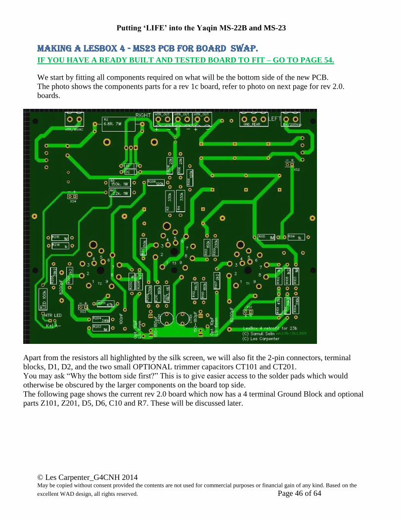
MAKING a Lesbox 4 - MS23 PCB for BOARD SWAP. IF YOU HAVE A READY BUILT AND TESTED BOARD TO FIT – GO TO PAGE 54.
We start by fitting all components required on what will be the bottom side of the new PCB.
The photo shows the components parts for a rev 1c board, refer to photo on next page for rev 2.0.
boards.
Apart from the resistors all highlighted by the silk screen, we will also fit the 2-pin connectors, terminal
blocks, D1, D2, and the two small OPTIONAL trimmer capacitors CT101 and CT201.
You may ask “Why the bottom side first?” This is to give easier access to the solder pads which would
otherwise be obscured by the larger components on the board top side.
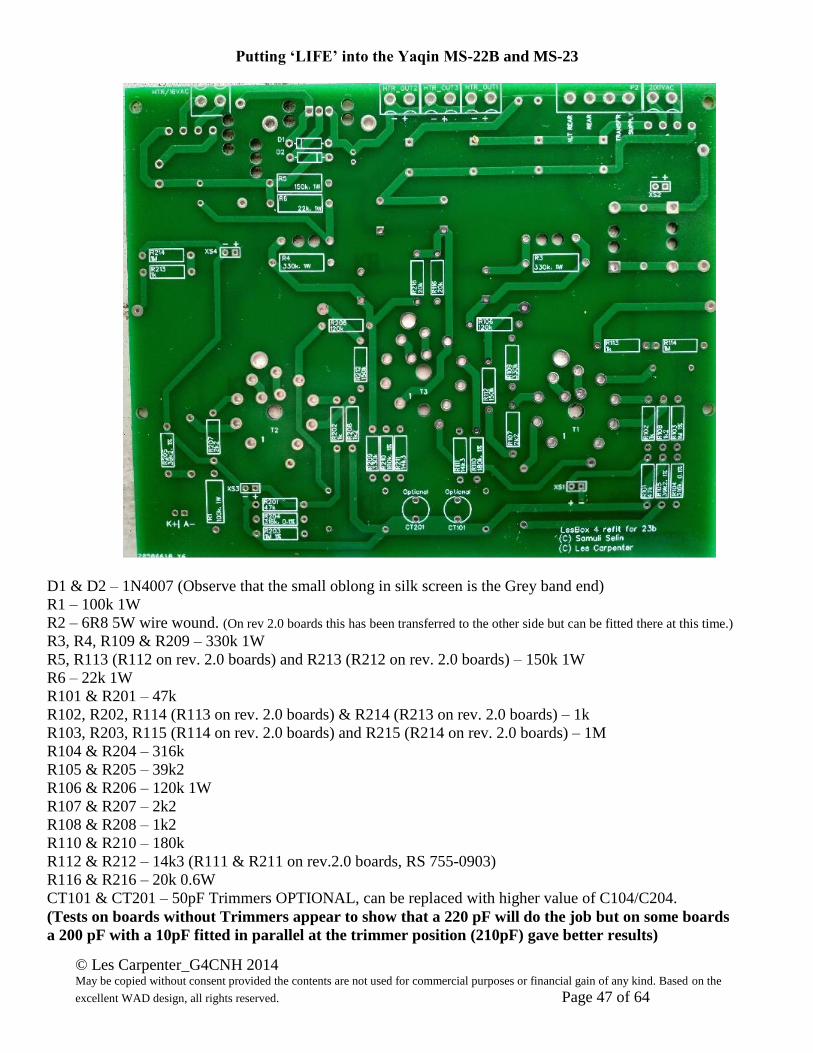
The following page shows the current rev 2.0 board which now has a 4 terminal Ground Block and optional
parts Z101, Z201, D5, D6, C10 and R7. These will be discussed later.
Putting ‘LIFE’ into the Yaqin MS-22B and MS-23
© Les Carpenter_G4CNH 2014 May be copied without consent provided the contents are not used for commercial purposes or financial gain of any kind. Based on the
excellent WAD design, all rights reserved. Page 47 of 64
D1 & D2 – 1N4007 (Observe that the small oblong in silk screen is the Grey band end)
R1 – 100k 1W
R2 – 6R8 5W wire wound. (On rev 2.0 boards this has been transferred to the other side but can be fitted there at this time.)
R3, R4, R109 & R209 – 330k 1W
R5, R113 (R112 on rev. 2.0 boards) and R213 (R212 on rev. 2.0 boards) – 150k 1W
R6 – 22k 1W
R101 & R201 – 47k
R102, R202, R114 (R113 on rev. 2.0 boards) & R214 (R213 on rev. 2.0 boards) – 1k
R103, R203, R115 (R114 on rev. 2.0 boards) and R215 (R214 on rev. 2.0 boards) – 1M
R104 & R204 – 316k
R105 & R205 – 39k2
R106 & R206 – 120k 1W
R107 & R207 – 2k2
R108 & R208 – 1k2
R110 & R210 – 180k
R112 & R212 – 14k3 (R111 & R211 on rev.2.0 boards, RS 755-0903)
R116 & R216 – 20k 0.6W
CT101 & CT201 – 50pF Trimmers OPTIONAL, can be replaced with higher value of C104/C204.
(Tests on boards without Trimmers appear to show that a 220 pF will do the job but on some boards
a 200 pF with a 10pF fitted in parallel at the trimmer position (210pF) gave better results)
Putting ‘LIFE’ into the Yaqin MS-22B and MS-23
© Les Carpenter_G4CNH 2014 May be copied without consent provided the contents are not used for commercial purposes or financial gain of any kind. Based on the
excellent WAD design, all rights reserved. Page 48 of 64
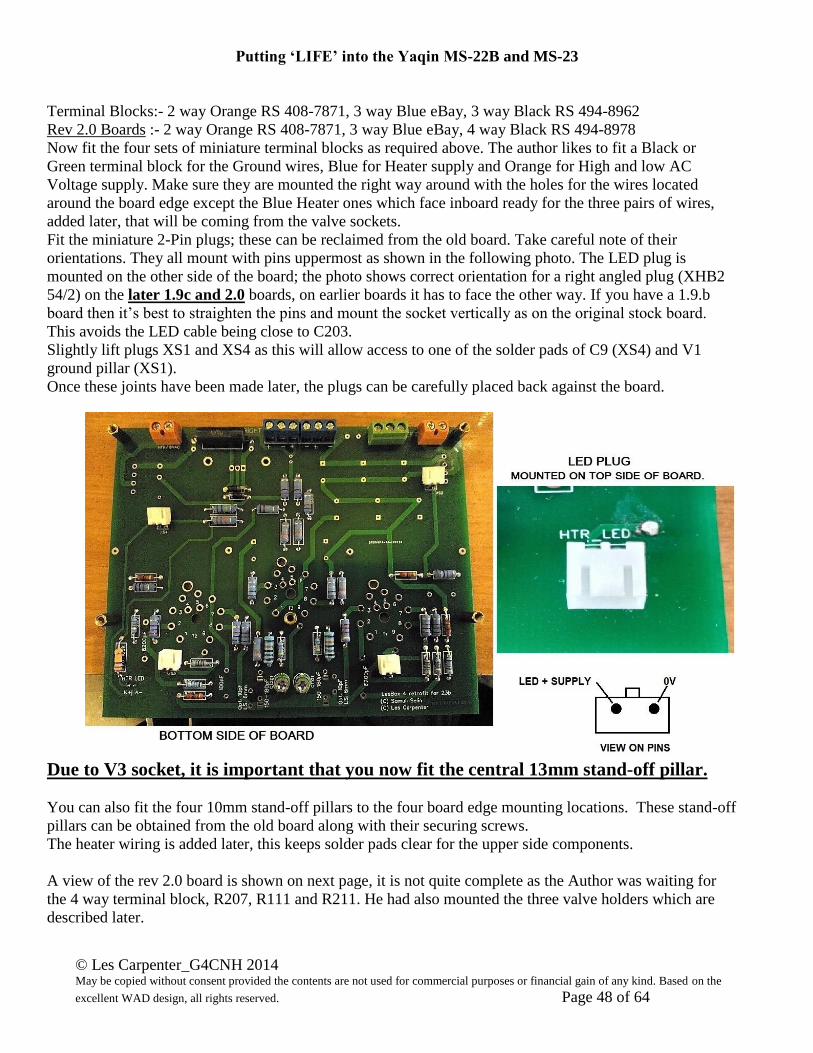
Terminal Blocks:- 2 way Orange RS 408-7871, 3 way Blue eBay, 3 way Black RS 494-8962
Rev 2.0 Boards :- 2 way Orange RS 408-7871, 3 way Blue eBay, 4 way Black RS 494-8978
Now fit the four sets of miniature terminal blocks as required above. The author likes to fit a Black or
Green terminal block for the Ground wires, Blue for Heater supply and Orange for High and low AC
Voltage supply. Make sure they are mounted the right way around with the holes for the wires located
around the board edge except the Blue Heater ones which face inboard ready for the three pairs of wires,
added later, that will be coming from the valve sockets.
Fit the miniature 2-Pin plugs; these can be reclaimed from the old board. Take careful note of their
orientations. They all mount with pins uppermost as shown in the following photo. The LED plug is
mounted on the other side of the board; the photo shows correct orientation for a right angled plug (XHB2
54/2) on the later 1.9c and 2.0 boards, on earlier boards it has to face the other way. If you have a 1.9.b
board then it’s best to straighten the pins and mount the socket vertically as on the original stock board.
This avoids the LED cable being close to C203.
Slightly lift plugs XS1 and XS4 as this will allow access to one of the solder pads of C9 (XS4) and V1
ground pillar (XS1).
Once these joints have been made later, the plugs can be carefully placed back against the board.
Due to V3 socket, it is important that you now fit the central 13mm stand-off pillar.
You can also fit the four 10mm stand-off pillars to the four board edge mounting locations. These stand-off
pillars can be obtained from the old board along with their securing screws.
The heater wiring is added later, this keeps solder pads clear for the upper side components.
A view of the rev 2.0 board is shown on next page, it is not quite complete as the Author was waiting for
the 4 way terminal block, R207, R111 and R211. He had also mounted the three valve holders which are
described later.

Putting ‘LIFE’ into the Yaqin MS-22B and MS-23
© Les Carpenter_G4CNH 2014 May be copied without consent provided the contents are not used for commercial purposes or financial gain of any kind. Based on the
excellent WAD design, all rights reserved. Page 49 of 64
Before building the top side of the board, some components require work of a mechanical kind.
The Regulator has to be mounted to the heat sink and will require a 6mm long M3 screw, shake proof
washer and nut. It is also required to be treated with a thin film of heat sink thermal compound so that its
metal tab makes a good thermal bond with the heat sink. There may be enough by re-using the old regulator
and salvaging what’s left remaining on the old heat sink.
The skirted valve holders are special and have integral grounding pillar, you need to add a 7mm M3 spacer
and a 4mm M3 screw on each flange to provide the same support distance.
Construction of the top side of the board should start with;-
a) D3 & D4 – Bridge rectifiers. Polarity is important!
b) 7812 Regulator – Fit complete with its heatsink (Stonecold HS-130-25).
c) Valve holders – For mounting the Banzai 18443 micalex valve holders, fit to the board and secure with
another 4mm M3 screw. Check the holder is square to the board, holding the assembly if required,
while soldering the Grounding stand-off lug. With its position now securely held you can solder all
nine pins of the holder.

Putting ‘LIFE’ into the Yaqin MS-22B and MS-23
© Les Carpenter_G4CNH 2014 May be copied without consent provided the contents are not used for commercial purposes or financial gain of any kind. Based on the
excellent WAD design, all rights reserved. Page 50 of 64
Now we add the remaining components, there are a number of electrolytic capacitors which MUST be
placed onto the board the correct way round.
The White segments in their respective circles are where the Negative (-) wire has to go and the larger
electrolytic capacitors have their Positive (+) wires indicated by a square solder pad rather than a round
one.
C1 – 1000uF 25V Body Height 21mm Width 12.8mm (RS 711-1148)
C2 – 100uF 25V Body Height 11.5mm Width 5.3mm (RS 519-4059)
C3 – 47uF 350V Body Height 21mm Width 16.3mm (RS 165-3965)
C4 – 47uF 350V Body as for C3
C5 – 47uF 350V Body as for C3
C6 – 47uF 350V Body as for C3
C7 – 47uF 350V Body as for C3
C8 – 47uF 350V Body as for C3
C9 – 47uF 100V Body Height 13mm Width 11mm (RS 365-4509)
C101 & C201 – 68uF 350V Body Height 26mm Width 16.2mm (RS 144-3947)
C102 & C202 – 100nF 400V (RS 755-4472)
C103 & C203 – 8200pF Silver Mica
C104 & C204 –160pF Silver Mica or alternative 220pF (see below in Bold).
The author adds a 10pF capacitor in the extra solder pads provided as this gives a better range to the
trimmers CT101 and CT210.
Alternatively if you have not fitted trimmer capacitors then C104 & C204 become 220pF 1%.
On the rev 2.0 boards the Author found some boards needed a 10pF capacitor (where the
trimmer would normally go) with a 200pF in the C104 and C204 positions to give the best RIAA
at 20 kHz.
C105 & C205 – 3.3uF 400V (Audyn M4)
R9 – 10k 5W radial wire wound resistor. (RS 199-7898)
On rev 2.0 boards the Optional Ground Lift components (if required) should now be fitted:-
R7 – 10 Ohm 5W resistor (RS 762-9175)
D5 & D6 – 6A Diodes SF63G (RS 688-2195)
C10 – 100nF 400V Capacitor (RS 755-4472)
On rev 2.0 boards the Optional Zener stabiliser diodes (if required) should now be fitted:-
Z101 & Z201 – 190V 5W 1N5387B
If you want to fit Zener diodes to the 1.9b or 1.9c boards then you can do this by placing them
across the 330k resistors R3 and R4. The Zener’s are recommended to be 5W 190V types such as
the 1N5387B but try not to bend the leads too close to the Zener body. Mounting them on the Top
side is recommended such that they are clear of the heater wiring which is on the Bottom side.
Make up three lengths of twisted wire suitable for the heater supplies, one length to be 85mm and the
other two 120mm each.
Connect one 120mm length between the first two terminal block positions and the heater pads of V2.
Connect the 85mm length between the next two (central) terminal block positions and the heater pads
of V3.
Putting ‘LIFE’ into the Yaqin MS-22B and MS-23
© Les Carpenter_G4CNH 2014 May be copied without consent provided the contents are not used for commercial purposes or financial gain of any kind. Based on the
excellent WAD design, all rights reserved. Page 51 of 64
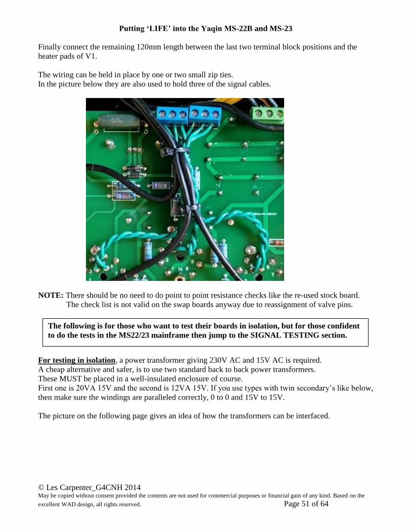
Finally connect the remaining 120mm length between the last two terminal block positions and the
heater pads of V1.
The wiring can be held in place by one or two small zip ties.
In the picture below they are also used to hold three of the signal cables.
NOTE: There should be no need to do point to point resistance checks like the re-used stock board.
The check list is not valid on the swap boards anyway due to reassignment of valve pins.
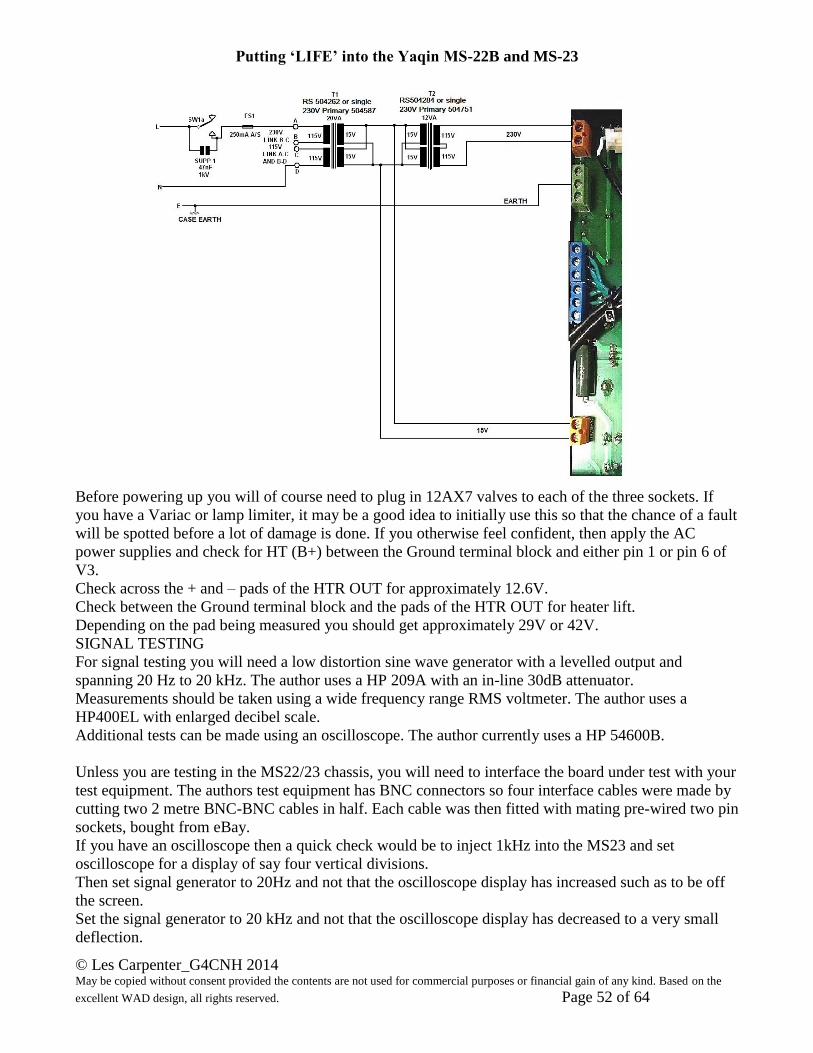
For testing in isolation, a power transformer giving 230V AC and 15V AC is required.
A cheap alternative and safer, is to use two standard back to back power transformers.
These MUST be placed in a well-insulated enclosure of course.
First one is 20VA 15V and the second is 12VA 15V. If you use types with twin secondary’s like below,
then make sure the windings are paralleled correctly, 0 to 0 and 15V to 15V.
The picture on the following page gives an idea of how the transformers can be interfaced.
The following is for those who want to test their boards in isolation, but for those confident
to do the tests in the MS22/23 mainframe then jump to the SIGNAL TESTING section.
Putting ‘LIFE’ into the Yaqin MS-22B and MS-23
© Les Carpenter_G4CNH 2014 May be copied without consent provided the contents are not used for commercial purposes or financial gain of any kind. Based on the
excellent WAD design, all rights reserved. Page 52 of 64
Before powering up you will of course need to plug in 12AX7 valves to each of the three sockets. If
you have a Variac or lamp limiter, it may be a good idea to initially use this so that the chance of a fault
will be spotted before a lot of damage is done. If you otherwise feel confident, then apply the AC
power supplies and check for HT (B+) between the Ground terminal block and either pin 1 or pin 6 of
V3.
Check across the + and – pads of the HTR OUT for approximately 12.6V.
Check between the Ground terminal block and the pads of the HTR OUT for heater lift.
Depending on the pad being measured you should get approximately 29V or 42V.
SIGNAL TESTING
For signal testing you will need a low distortion sine wave generator with a levelled output and
spanning 20 Hz to 20 kHz. The author uses a HP 209A with an in-line 30dB attenuator.
Measurements should be taken using a wide frequency range RMS voltmeter. The author uses a
HP400EL with enlarged decibel scale.
Additional tests can be made using an oscilloscope. The author currently uses a HP 54600B.
Unless you are testing in the MS22/23 chassis, you will need to interface the board under test with your
test equipment. The authors test equipment has BNC connectors so four interface cables were made by
cutting two 2 metre BNC-BNC cables in half. Each cable was then fitted with mating pre-wired two pin
sockets, bought from eBay.
If you have an oscilloscope then a quick check would be to inject 1kHz into the MS23 and set
oscilloscope for a display of say four vertical divisions.
Then set signal generator to 20Hz and not that the oscilloscope display has increased such as to be off
the screen.
Set the signal generator to 20 kHz and not that the oscilloscope display has decreased to a very small
deflection.
Putting ‘LIFE’ into the Yaqin MS-22B and MS-23
© Les Carpenter_G4CNH 2014 May be copied without consent provided the contents are not used for commercial purposes or financial gain of any kind. Based on the
excellent WAD design, all rights reserved. Page 53 of 64
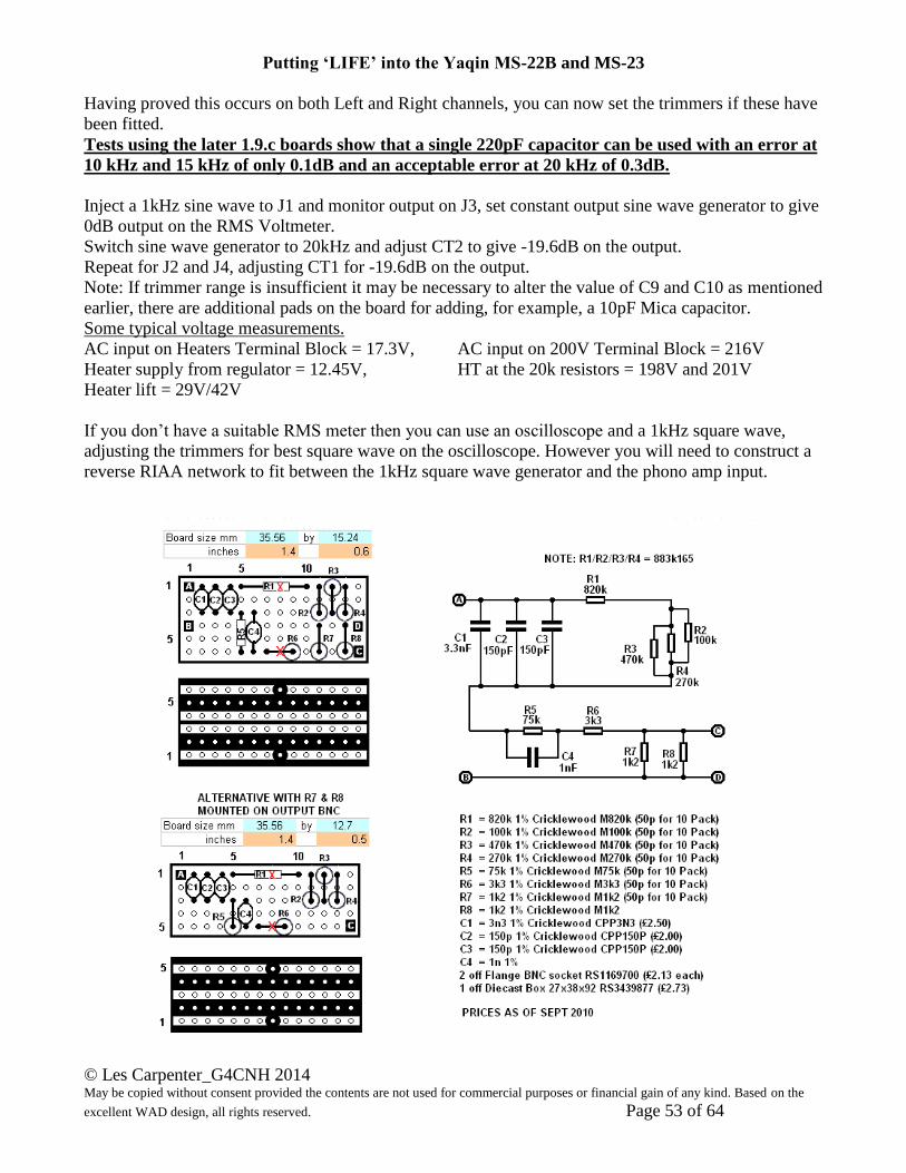
Having proved this occurs on both Left and Right channels, you can now set the trimmers if these have
been fitted.
Tests using the later 1.9.c boards show that a single 220pF capacitor can be used with an error at
10 kHz and 15 kHz of only 0.1dB and an acceptable error at 20 kHz of 0.3dB.
Inject a 1kHz sine wave to J1 and monitor output on J3, set constant output sine wave generator to give
0dB output on the RMS Voltmeter.
Switch sine wave generator to 20kHz and adjust CT2 to give -19.6dB on the output.
Repeat for J2 and J4, adjusting CT1 for -19.6dB on the output.
Note: If trimmer range is insufficient it may be necessary to alter the value of C9 and C10 as mentioned
earlier, there are additional pads on the board for adding, for example, a 10pF Mica capacitor.
Some typical voltage measurements.
AC input on Heaters Terminal Block = 17.3V, AC input on 200V Terminal Block = 216V
Heater supply from regulator = 12.45V, HT at the 20k resistors = 198V and 201V
Heater lift = 29V/42V
If you don’t have a suitable RMS meter then you can use an oscilloscope and a 1kHz square wave,
adjusting the trimmers for best square wave on the oscilloscope. However you will need to construct a
reverse RIAA network to fit between the 1kHz square wave generator and the phono amp input.
Putting ‘LIFE’ into the Yaqin MS-22B and MS-23
© Les Carpenter_G4CNH 2014 May be copied without consent provided the contents are not used for commercial purposes or financial gain of any kind. Based on the
excellent WAD design, all rights reserved. Page 54 of 64
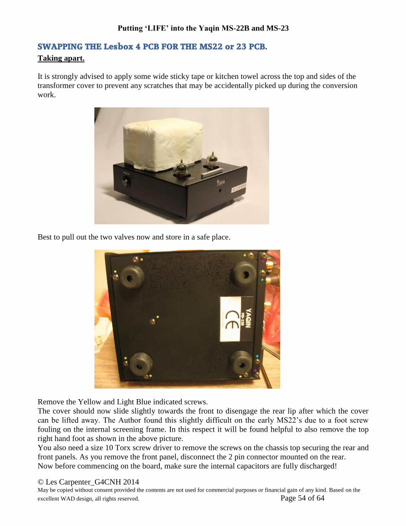
SWAPPING THE Lesbox 4 PCB FOR THE MS22 or 23 PCB.
Taking apart.
It is strongly advised to apply some wide sticky tape or kitchen towel across the top and sides of the
transformer cover to prevent any scratches that may be accidentally picked up during the conversion
work.
Best to pull out the two valves now and store in a safe place.
Remove the Yellow and Light Blue indicated screws.
The cover should now slide slightly towards the front to disengage the rear lip after which the cover
can be lifted away. The Author found this slightly difficult on the early MS22’s due to a foot screw
fouling on the internal screening frame. In this respect it will be found helpful to also remove the top
right hand foot as shown in the above picture.
You also need a size 10 Torx screw driver to remove the screws on the chassis top securing the rear and
front panels. As you remove the front panel, disconnect the 2 pin connector mounted on the rear.
Now before commencing on the board, make sure the internal capacitors are fully discharged!

Putting ‘LIFE’ into the Yaqin MS-22B and MS-23
© Les Carpenter_G4CNH 2014 May be copied without consent provided the contents are not used for commercial purposes or financial gain of any kind. Based on the
excellent WAD design, all rights reserved. Page 55 of 64
With your Multimeter switched to DC Volts check across + and – of C17 to ensure the capacitors are
all but discharged. These can be discharged if necessary by holding a suitable low value resistor (a 1k2
1W should do) across + and – of C17 for 20 seconds (see next photo).
Now detach the four white plugs from the circuit board connectors, don’t worry, they are easy to
identify when it comes to re-assembly.
With reference to the following photo, now cut the two White wires (on later MS23B models this
may be a 2 pin plug with Blue wires), BUT ensure the cut is as close to the solder point as possible as
spare wiring is at a premium. With respect to the 2 pin plug with Blue wires, then likewise cut off the
plug but as close to the connector as you can. These wires carry AC voltages so it does not matter
which way round they go when you terminate them later into their designated screw terminals.
Now cut off the two Yellow wires as close to the solder point as possible.
These wires also carry AC voltages so it does not matter which way round they go when you terminate
them later.
Now cut off the Ground wires, there may be as many as three, sometimes they are coloured
Yellow/Green else simply Black but once again, save as much wire length as you can while doing this.
There is normally an Earth wire going to the circuit board at the position marked G2. On the MS23
there may be two black wires on G2 and not a Yellow/Green wire as shown. In fact there have been a
number of production variations, some will go to G2, some to the STAR Point, some use a connection
to the left of the STAR (hidden by the Yellow twisted wires) and some units even have a connection on
the ground track that connects to the lower electrolytic capacitors C15 and C16.
Putting ‘LIFE’ into the Yaqin MS-22B and MS-23
© Les Carpenter_G4CNH 2014 May be copied without consent provided the contents are not used for commercial purposes or financial gain of any kind. Based on the
excellent WAD design, all rights reserved. Page 56 of 64
The circuit board should now be removed; this is held in by four countersunk head 3mm screws.
Put these safely away with the other screws you removed as they will be needed for the new fit.
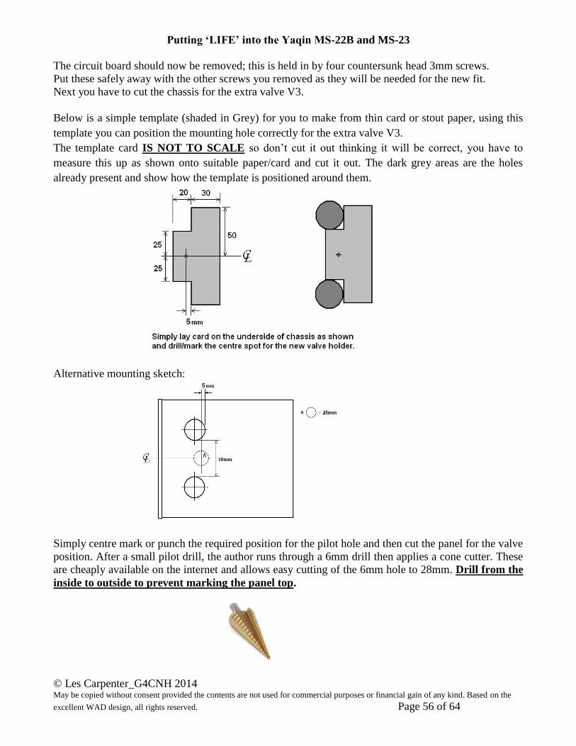
Next you have to cut the chassis for the extra valve V3.
Below is a simple template (shaded in Grey) for you to make from thin card or stout paper, using this
template you can position the mounting hole correctly for the extra valve V3.
The template card IS NOT TO SCALE so don’t cut it out thinking it will be correct, you have to
measure this up as shown onto suitable paper/card and cut it out. The dark grey areas are the holes
already present and show how the template is positioned around them.
Alternative mounting sketch:
Simply centre mark or punch the required position for the pilot hole and then cut the panel for the valve
position. After a small pilot drill, the author runs through a 6mm drill then applies a cone cutter. These
are cheaply available on the internet and allows easy cutting of the 6mm hole to 28mm. Drill from the
inside to outside to prevent marking the panel top.
Putting ‘LIFE’ into the Yaqin MS-22B and MS-23
© Les Carpenter_G4CNH 2014 May be copied without consent provided the contents are not used for commercial purposes or financial gain of any kind. Based on the
excellent WAD design, all rights reserved. Page 57 of 64
Be careful of machining operation swarf when cutting the large hole for the extra valve. It helps to keep
the amplifier body tilted forward slightly during these operations to prevent metal particles finding their
way into the power transformer cover. The author runs a wide tip Black Sharpie around the inside of
the new hole to make it look like the other two.
Fit the four 10mm threaded pillars and countersunk screws from the old board and offer up the new
board to the chassis. Don’t actually secure the board yet as you may appreciate a bit of room to get the
wires into the terminal blocks.
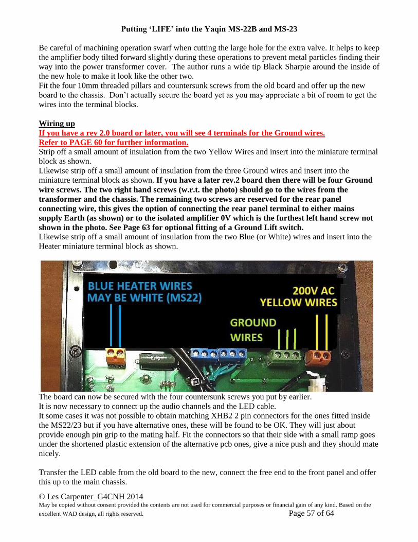
Wiring up
If you have a rev 2.0 board or later, you will see 4 terminals for the Ground wires.
Refer to PAGE 60 for further information.
Strip off a small amount of insulation from the two Yellow Wires and insert into the miniature terminal
block as shown.
Likewise strip off a small amount of insulation from the three Ground wires and insert into the
miniature terminal block as shown. If you have a later rev.2 board then there will be four Ground
wire screws. The two right hand screws (w.r.t. the photo) should go to the wires from the
transformer and the chassis. The remaining two screws are reserved for the rear panel
connecting wire, this gives the option of connecting the rear panel terminal to either mains
supply Earth (as shown) or to the isolated amplifier 0V which is the furthest left hand screw not
shown in the photo. See Page 63 for optional fitting of a Ground Lift switch.
Likewise strip off a small amount of insulation from the two Blue (or White) wires and insert into the
Heater miniature terminal block as shown.
The board can now be secured with the four countersunk screws you put by earlier.
It is now necessary to connect up the audio channels and the LED cable.
It some cases it was not possible to obtain matching XHB2 2 pin connectors for the ones fitted inside
the MS22/23 but if you have alternative ones, these will be found to be OK. They will just about
provide enough pin grip to the mating half. Fit the connectors so that their side with a small ramp goes
under the shortened plastic extension of the alternative pcb ones, give a nice push and they should mate
nicely.
Transfer the LED cable from the old board to the new, connect the free end to the front panel and offer
this up to the main chassis.
Putting ‘LIFE’ into the Yaqin MS-22B and MS-23
© Les Carpenter_G4CNH 2014 May be copied without consent provided the contents are not used for commercial purposes or financial gain of any kind. Based on the
excellent WAD design, all rights reserved. Page 58 of 64
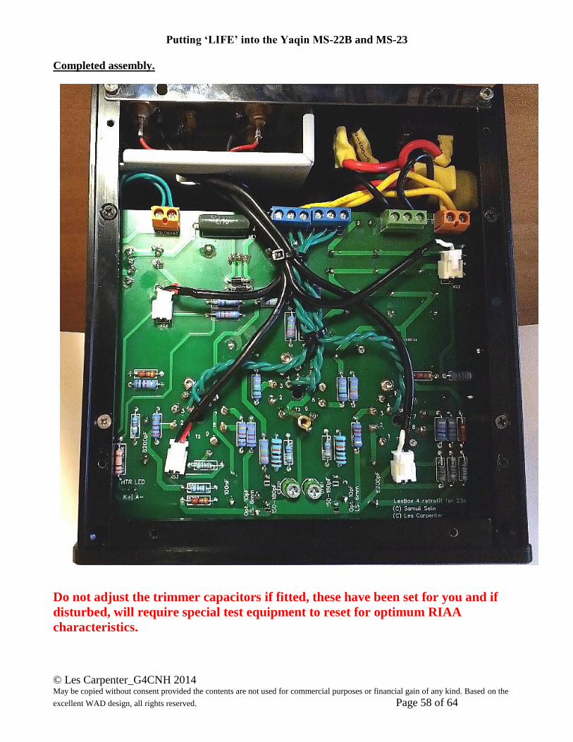
Completed assembly.
Do not adjust the trimmer capacitors if fitted, these have been set for you and if
disturbed, will require special test equipment to reset for optimum RIAA
characteristics.
Putting ‘LIFE’ into the Yaqin MS-22B and MS-23
© Les Carpenter_G4CNH 2014 May be copied without consent provided the contents are not used for commercial purposes or financial gain of any kind. Based on the
excellent WAD design, all rights reserved. Page 59 of 64
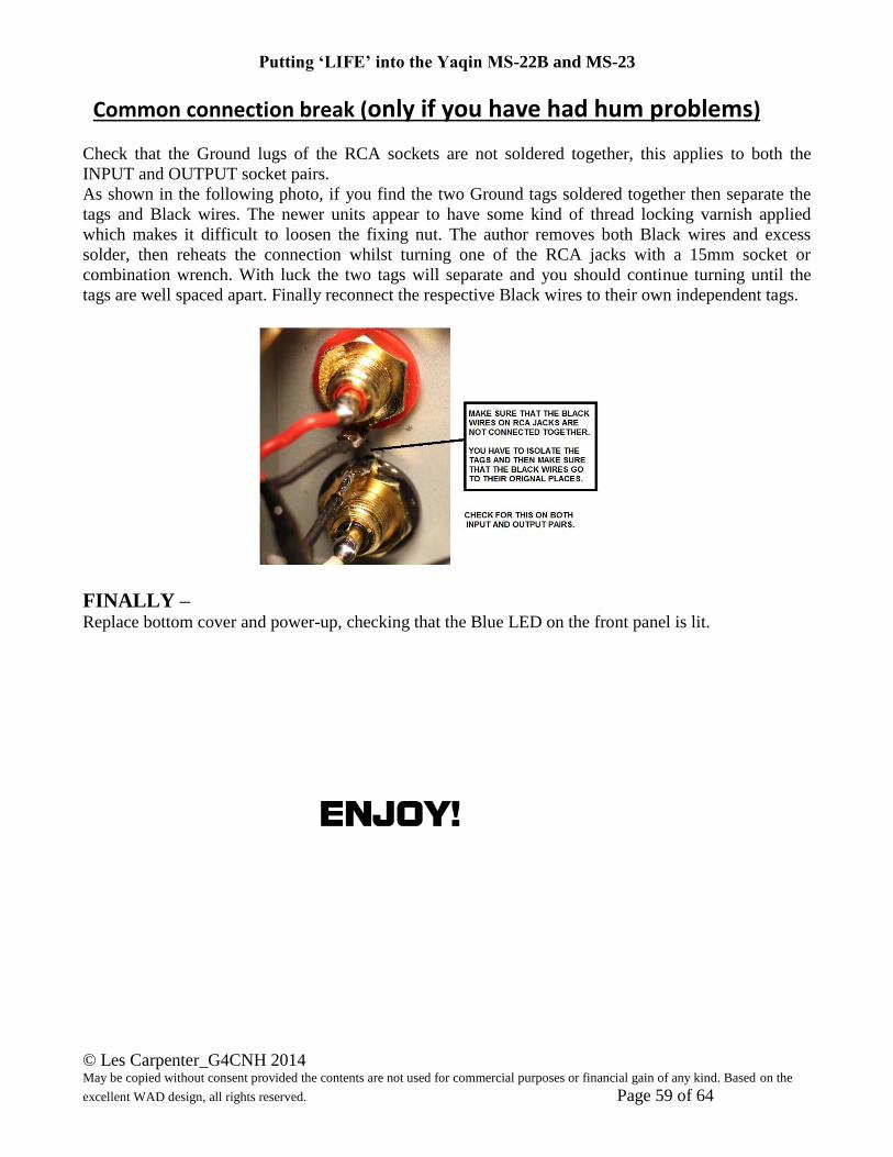
Common connection break (only if you have had hum problems) Check that the Ground lugs of the RCA sockets are not soldered together, this applies to both the
INPUT and OUTPUT socket pairs.
As shown in the following photo, if you find the two Ground tags soldered together then separate the
tags and Black wires. The newer units appear to have some kind of thread locking varnish applied
which makes it difficult to loosen the fixing nut. The author removes both Black wires and excess
solder, then reheats the connection whilst turning one of the RCA jacks with a 15mm socket or
combination wrench. With luck the two tags will separate and you should continue turning until the
tags are well spaced apart. Finally reconnect the respective Black wires to their own independent tags.
FINALLY – Replace bottom cover and power-up, checking that the Blue LED on the front panel is lit.
ENJOY!

Putting ‘LIFE’ into the Yaqin MS-22B and MS-23
© Les Carpenter_G4CNH 2014 May be copied without consent provided the contents are not used for commercial purposes or financial gain of any kind. Based on the
excellent WAD design, all rights reserved. Page 60 of 64
Putting ‘LIFE’ into the Yaqin MS-22B and MS-23
© Les Carpenter_G4CNH 2014 May be copied without consent provided the contents are not used for commercial purposes or financial gain of any kind. Based on the
excellent WAD design, all rights reserved. Page 61 of 64
SWAPPING THE Lesbox 4 PCB rev 2.0 FOR THE MS23 PCB.
The rev.2 circuit board has the following differences.
1) The amplifier 0V line is fully isolated from the mains supply safety earth which should go a long
way in removing any hum loops that may appear between the MS23/Lesbox and turntables.
2) The mains supply safety earth will go to the chassis (most important), the mains transformer and
the screening covers of the three tubes. It will also go to the rear panel terminal BUT there is now
the option to move the connection on the 4 terminal Ground block (previously 3 terminals) so that
the rear panel terminal can, as an alternative, go to the amplifier 0V line instead.
It is possible to fit a single pole 2 way toggle switch on the rear panel so that you can select either
option at will. (See Page 63) but heed the warning regarding the type of rear panel!
3) The mains supply safety earth is now coupled to the amplifier 0V line via a Ground Lift network.
This consists of a 10 Ohm 5W resistor and 100nF capacitor, guarded against fault conditions by
high current diodes. This is purely as a safeguard in case of a very remote chance that AC mains
power somehow managed to leak onto the amplifier 0V line. The network however maintains the
required earth loop break required to reduce hum from circulating currents in the grounding
system. The effect of switching to Ground Lift can be quite amazing in hum reduction.
4) 5W 190V Zener diodes 1N5387B (Z101 and Z201) have been fitted after the 20k resistors R116
and R216 such as to help stabilise the B+ supply to the front end tubes. The pictures below show
the no signal output variation caused by mains fluctuations over a time period of 50 seconds, the
left hand photo without the diodes and the right hand with 190V Zener diodes fitted.
Where the Zener diodes fit on a 1.9c Board.
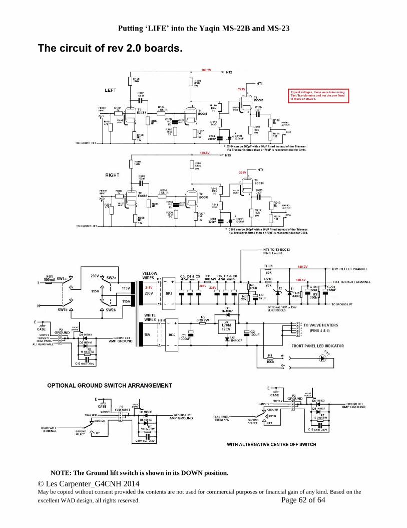
Putting ‘LIFE’ into the Yaqin MS-22B and MS-23
© Les Carpenter_G4CNH 2014 May be copied without consent provided the contents are not used for commercial purposes or financial gain of any kind. Based on the
excellent WAD design, all rights reserved. Page 62 of 64
The circuit of rev 2.0 boards.
NOTE: The Ground lift switch is shown in its DOWN position.

Putting ‘LIFE’ into the Yaqin MS-22B and MS-23
© Les Carpenter_G4CNH 2014 May be copied without consent provided the contents are not used for commercial purposes or financial gain of any kind. Based on the
excellent WAD design, all rights reserved. Page 63 of 64
Optional Ground Lift Switch This will save you having to take the bottom cover off each time you may want to experiment with the
grounding on different Turntables or Amplifiers.
Alternative Ground Lift Switch position
As mentioned above, this is necessary where the rear panel is of dark glossy appearance and with
White lettering, the material has proven to be extremely difficult to drill and is best left alone.
It is possible to mount the switch onto the base plate and an example position for this is as shown.
WARNING! If your MS23 does not have
a light grey panel as shown but a darker
glossy panel with White lettering, then this is
going to be difficult. The metal is some kind
of stainless steel and incredibly hard to drill.
The Author purchased some special Extreme
Stainless Steel drills with dual cutting heads
and even these hardly made a mark on the
panel.
It would therefor perhaps be more sensible to
mount a small slide or short toggle switch in
a convenient position onto the bottom plate.
This is shown below.
The hole required will depend on the switch fitted,
normally 5.5 or 6mm, together with an anti-rotation hole
drilled to suit.
It has to have a short toggle else the feet will not
properly engage with the surface on which the phono
amp is positioned.
A suitable 3 position toggle would be the RS 734-7233
Having a 5mm length toggle and requiring a 6.35mm
mounting hole.
Alternatively you can fit a standard single pole change
over switch such as the RS 734-7097, the missing
‘open’ position can be emulated by simply removing the
turntable Ground wire from the rear panel terminal.
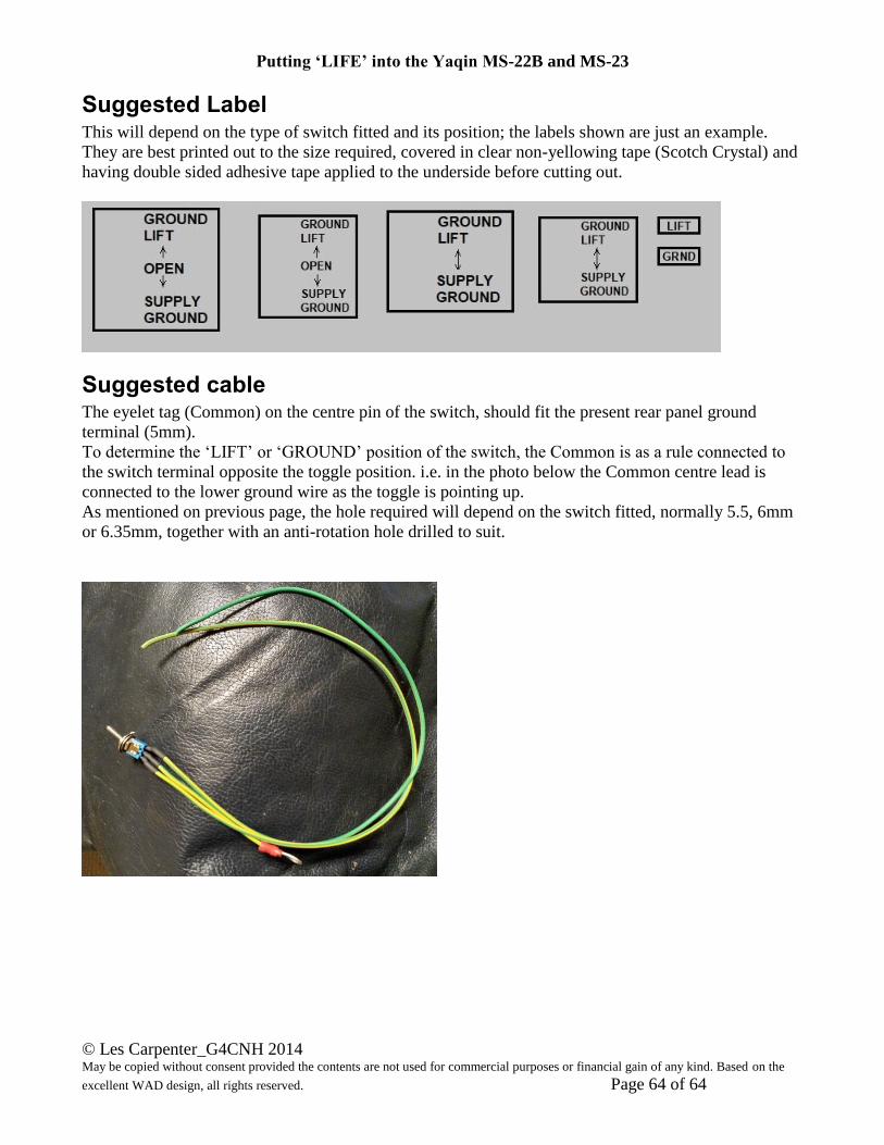
Putting ‘LIFE’ into the Yaqin MS-22B and MS-23
© Les Carpenter_G4CNH 2014 May be copied without consent provided the contents are not used for commercial purposes or financial gain of any kind. Based on the
excellent WAD design, all rights reserved. Page 64 of 64
Suggested Label This will depend on the type of switch fitted and its position; the labels shown are just an example.
They are best printed out to the size required, covered in clear non-yellowing tape (Scotch Crystal) and
having double sided adhesive tape applied to the underside before cutting out.
Suggested cable The eyelet tag (Common) on the centre pin of the switch, should fit the present rear panel ground
terminal (5mm).
To determine the ‘LIFT’ or ‘GROUND’ position of the switch, the Common is as a rule connected to
the switch terminal opposite the toggle position. i.e. in the photo below the Common centre lead is
connected to the lower ground wire as the toggle is pointing up.
As mentioned on previous page, the hole required will depend on the switch fitted, normally 5.5, 6mm
or 6.35mm, together with an anti-rotation hole drilled to suit.