Embed Size (px)
Citation preview

PUT COIN AND DRAW POWER
BY, HARI .R JINCY K.M
KANNAN C.V KRISHNAKANTH TIWARI

The aim of our project is to build a device which can be used to consume power on prepaid basis.
AIM

The system makes use of a sensor for detecting the coin.
A microcontroller that counts the coins and shows count on 7-segment display.
Relay energizes to connect the load and the coin count starts decrementing.
When count decrements to zero, the relay de-energizes to disconnect the load
ABSTRACT
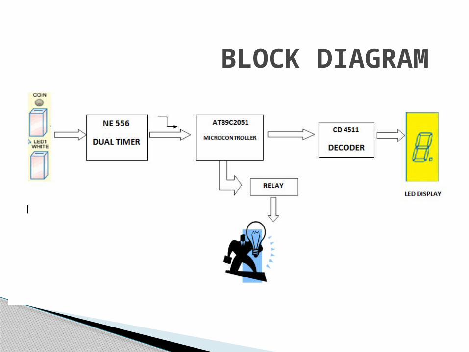
BLOCK DIAGRAM
NE 556 DUAL TIMER IC
AT89C2051 MICROCONTROLLER
CD 4511 DECODER IC
LTS543 COMMON CATHODE 7-SEGMENT DISPLAY
HARDWARE SPECIFICATIONS
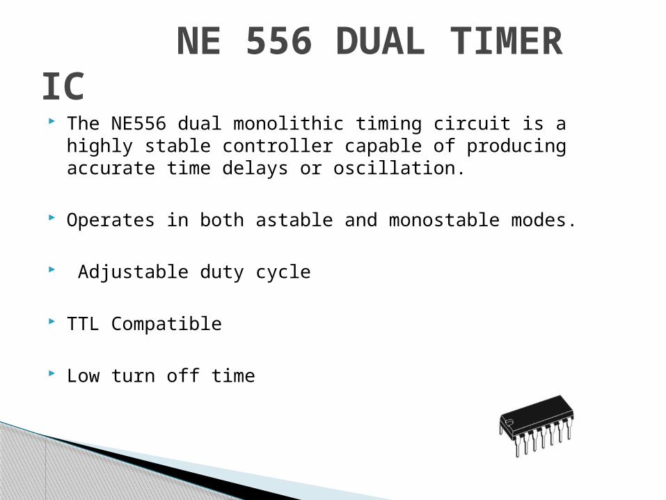
The NE556 dual monolithic timing circuit is a highly stable controller capable of producing accurate time delays or oscillation.
Operates in both astable and monostable modes.
Adjustable duty cycle
TTL Compatible
Low turn off time
NE 556 DUAL TIMER IC
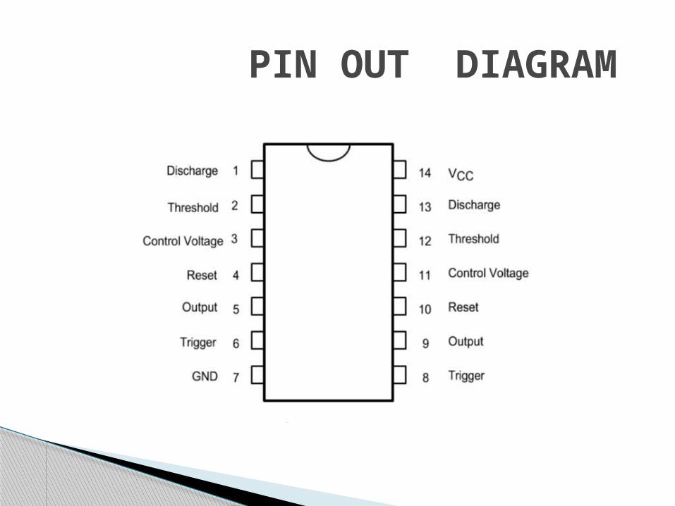
PIN OUT DIAGRAM
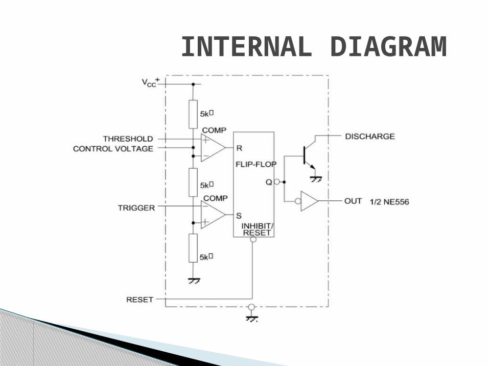
INTERNAL DIAGRAM

Heart of the circuit Low voltage , High performance CMOS 8-bit
microcomputer Highly flexible Cost effective solution to many embedded control
applications
AT89C2051 MICROCONTROLLER

PIN OUT DIAGRAM
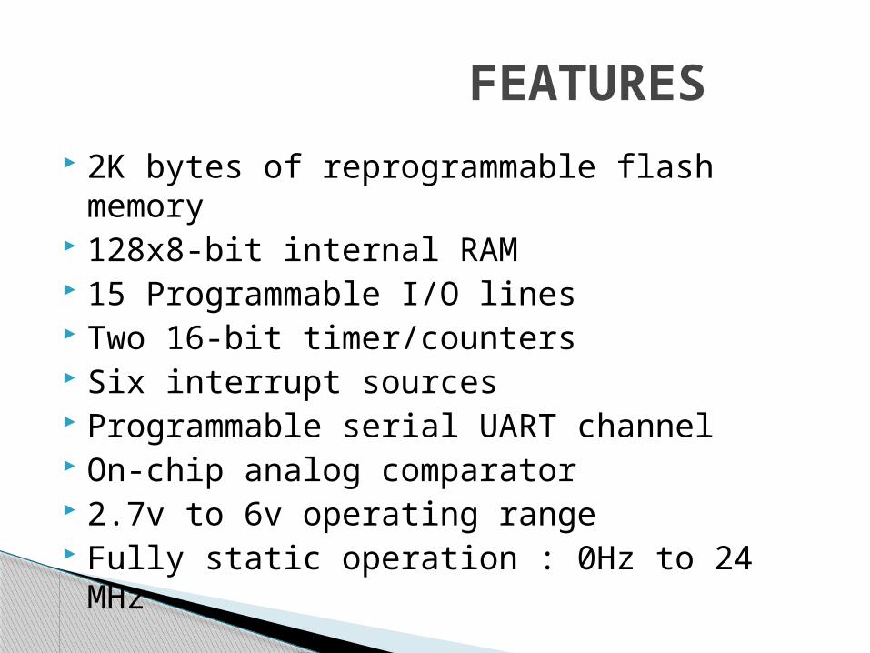
2K bytes of reprogrammable flash memory 128x8-bit internal RAM 15 Programmable I/O lines Two 16-bit timer/counters Six interrupt sources Programmable serial UART channel On-chip analog comparator 2.7v to 6v operating range Fully static operation : 0Hz to 24 MHz
FEATURES

BLOCK DIAGRAM
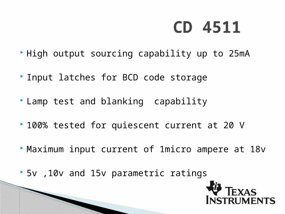
High output sourcing capability up to 25mA
Input latches for BCD code storage
Lamp test and blanking capability
100% tested for quiescent current at 20 V
Maximum input current of 1micro ampere at 18v
5v ,10v and 15v parametric ratings
CD 4511
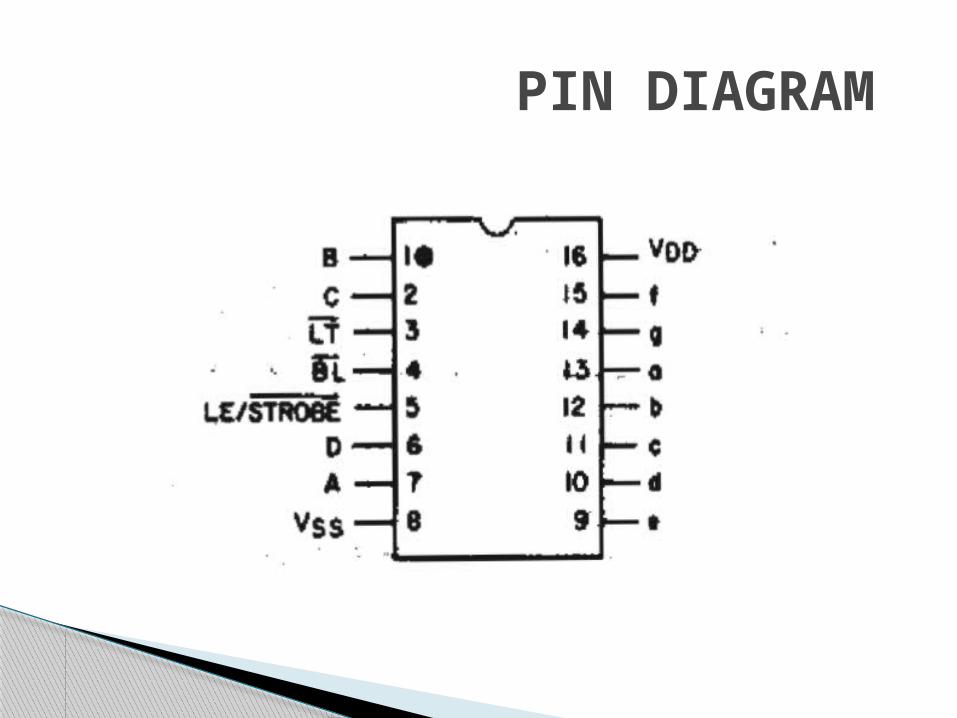
PIN DIAGRAM
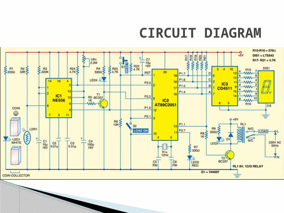
CIRCUIT DIAGRAM

When coin is inserted , it interrupts the light falling on LDR.
The trigger pin 6 of IC NE 556 goes high to make output pin 5 low.
The high to low pulse is used by AT89C2051 microcontroller to display the coin count.
After inserting the coin ,close the load switch
Port pin 1 of microcontroller goes high to drive the transistor to saturation
WORKING
Relay energizes and LED3 glows to indicate that load is switched on
As power is drawn by the load , the count shown in the 7-segment display decrements
Port pin P1.0 of the microcontroller triggers the second timer of NE 556
When trigger pin 8 of NE 556 goes low its output pin 9 goes high for a time period decided by preset Vr1 and capacitor C4
The high output of the timer is inverted by transistor T1 and fed to port pin P3.2
The count display decrements by 1 after P3.2 receive five pulses (indicated by LED 4)
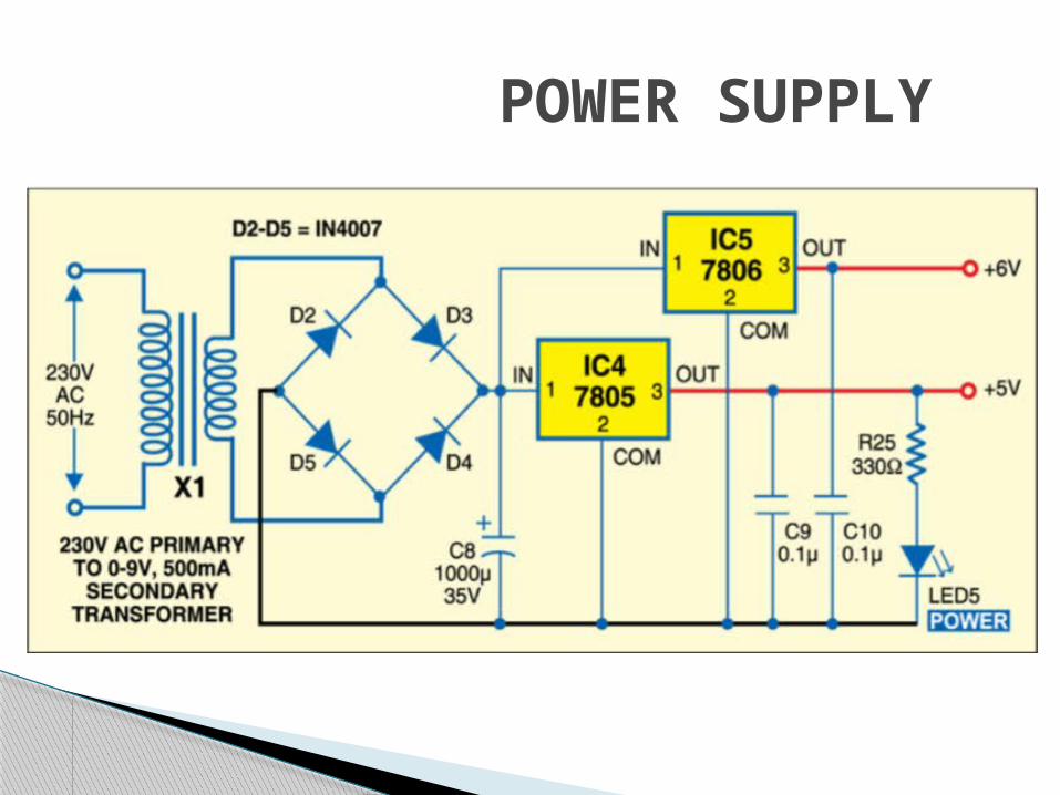
POWER SUPPLY
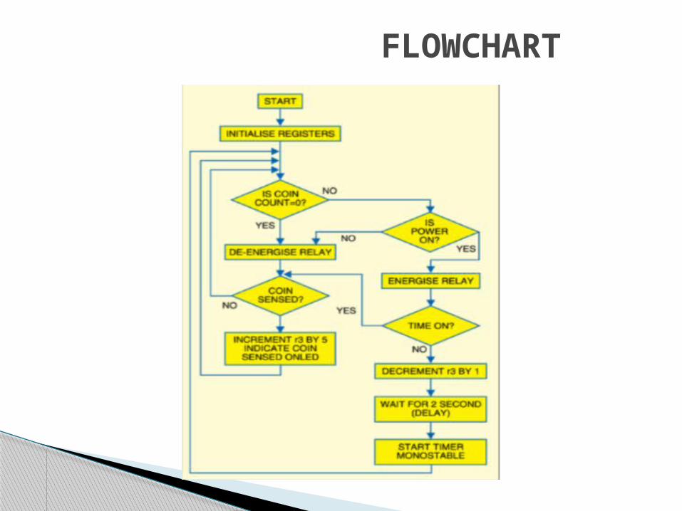
FLOWCHART
Built on the lines of payphones
Payloads like lamps and air conditioners to be used on a private electrical line
Useful for paying guest houses , lodges and trains
APPLICATIONS

This project is one of the best way of saving power .
The components used in the project are very cheap and easily available in the market
CONCLUSION

THANK YOUBY
GROUP 6