Embed Size (px)
Citation preview

CONTENTS
Description . . . . . . . . . . . . . . . . . . . . . . . . . . . . . . . . . . . . . . . . . . . . . . . . . . . . .PageGeneral Characteristics . . . . . . . . . . . . . . . . . . . . . . . . . . . . . . . . . . . . . . . . . . . . . 314Non-Illuminated Operators . . . . . . . . . . . . . . . . . . . . . . . . . . . . . . . . . . . . . . . . . . . 315Mushroom Operators and Yellow Contrast Plates . . . . . . . . . . . . . . . . . . . . . . . . . 317Two Button Operators. . . . . . . . . . . . . . . . . . . . . . . . . . . . . . . . . . . . . . . . . . . . . . . 319Specialty Operators . . . . . . . . . . . . . . . . . . . . . . . . . . . . . . . . . . . . . . . . . . . . . . . . 320Reset Operators . . . . . . . . . . . . . . . . . . . . . . . . . . . . . . . . . . . . . . . . . . . . . . . . . . . 321Contact Blocks . . . . . . . . . . . . . . . . . . . . . . . . . . . . . . . . . . . . . . . . . . . . . . . . . . . . 322Pilot Lights and Light Modules . . . . . . . . . . . . . . . . . . . . . . . . . . . . . . . . . . . . . . . . 323Illuminated Operators . . . . . . . . . . . . . . . . . . . . . . . . . . . . . . . . . . . . . . . . . . . . . . . 324Light Module Assemblies . . . . . . . . . . . . . . . . . . . . . . . . . . . . . . . . . . . . . . . . . . . . 328Specialty Light Modules . . . . . . . . . . . . . . . . . . . . . . . . . . . . . . . . . . . . . . . . . . . . . 330Accessories and Replacement Parts . . . . . . . . . . . . . . . . . . . . . . . . . . . . . . . . . . . 331Legend Plates. . . . . . . . . . . . . . . . . . . . . . . . . . . . . . . . . . . . . . . . . . . . . . . . . . . . . 333Dimensions . . . . . . . . . . . . . . . . . . . . . . . . . . . . . . . . . . . . . . . . . . . . . . . . . . . . . . . 334XB2B 22 mm Mounting Instructions . . . . . . . . . . . . . . . . . . . . . . . . . . . . . . . . . . . . 336Declaration of Conformity . . . . . . . . . . . . . . . . . . . . . . . . . . . . . . . . . . . . . . . . . . . . 350Schneider Electric Brands
File 9001
Push Buttons and Operator InterfaceSpecifier’s GuideType XB2B 22 mm Diecast Chrome Plated
Courtesy of Steven Engineering, Inc. ! 230 Ryan Way, South San Francisco, CA 94080-6370 ! Main Office: (650) 588-9200 ! Outside Local Area: (800) 258-9200 ! www.stevenengineering.com

Push Buttons and Operator Interface Specifiers GuideXB2B 22 mmGeneral Characteristics
© 1999 - 2000 Schneider Electric All Rights Reserved314
11/00
Limited AvailabilityFor replacement use only.
For new applications, use XB4 (page 37 - 72)
EnvironmentConformity to standards XB2B, XD2P: UL 508, IEC 60947-5-1, EN60947-5-1, IEC 60337-1, IEC 60337-2, NF C 63-140, ASE 0119, ASE1003 ,
BS 4794, VDE 0660-200, CSA C 22-2 No. 14, CSA C 22-2 No. 66
Approvals UL: push buttons and selector switches NEMA / UL Type A600-Q600;pilot lights and illuminated push buttons direct supply (120 V max.);pilot lights and illuminated push buttons with transformer (600 V)CSA: push buttons and selector switches NEMA / UL Type A600-Q600.pilot lights and illuminated push buttons direct supply (120 V max.);pilot lights and illuminated push buttons with transformer (600 V).ASE, DEMKO, NEMKO, SEMKO, BUREAU VERITAS, SAHKOTARKASTUSKESKUS, GL, DNV, LROSXD2P, standard version: CSA A600-Q600, LROS.
Protective treatment Standard version: TC “All climates”
Ambient temperature Operating: -25 °C to +70 °C (-13 °F to +158 °F) Storage: -40 °C to +70 °C (-40 °F to +158 °F)
Resistance to vibration 60 mm diameter mushroom head: 8 g. Other push buttons: 15 g. Small joystick controllers: 5 g (from 40 to 50 Hz)Conforming to IEC 60068-2-6.
Resistance to shock Push buttons: 70 g. Mushroom head push-buttons: 15 g. Selector switches: 200 g. Conforming to IEC 60068-2-27.
Protection against electric shock XB2B, XD2P: Class 1, conforming to IEC 60536 and NF C 20-030.
Degree of protectionconforming to IEC 60529and NF C 20-010
NEMA / UL ratings XB2B: 1, 2, 3, 4, 4X, 12K, 13, XB2B, XD2P: IP 65: flush and protecting, illuminated and non-illuminated push buttons (mounted). IP 66: booted and mushroom head push buttons, selector switches, pilot lights and small joystick controllers (mounted). IP 40: double- headed push buttons (IP 65 on request).
Mechanical life Push buttons—3 million operations (Latching mushroom head push buttons: 300,000 operations. Illuminated selector switches: 100,000 operations). The product life expressed is based on average usage and normal operating conditions. Actual operating life will vary with conditions. The above statements are not intended to nor shall they create any express or implied warranties as to product operation or life. For information on the limited warranty offered on this product, please refer to Square D terms and conditions of sale found in the Square D Digest.
Contact block characteristicsNominal thermal current 10 A conforming to IEC 60947-5-1, NF C 63-140, UL 508, CSA 22-2 No. 14, VDE 0660 part 2, NEMA / UL Type A600-Q600.
Nominal insulation voltage 500 V conforming to NF C 20-040, VDE 0110, IEC 60158-1, 600 V conforming to UL 508, 600 V conforming to CSA 22-2 No. 14.
Insulation category Group C conforming to NF C 20-040 and VDE 0110.
Contact operation Slow- make N.O. or slow-break N.C. with direct opening operation conforming to EN60947-5-1section 3.
Contact resistance ð25 m¾ conforming to: NF C 93-050 method A or IEC 60225-7 category 3.
Operating force Flush or projecting push buttons - with 1 NO contact: 2.25 lb - with 1 NC contact: 1.8 lbAdditional contacts - N.O.: add 1 lb - N.C.: add 0.7 lb.
Terminal referencing Conforming to CENELEC EN 50013.
Short circuit protection 10 A cartridge fuses, Gl or N conforming to IEC 60269-1and VDE 0660-200.
Rated powerconforming to IEC 60947-5-1 Appendix Cduty categories AC11-DC11Operating frequency: 3,600 ops/hourLoad factor: 0.5AC supply (50-60 Hz)
Cabling XB2B, XD2P: Screw and captive clamp terminals. Recommended torque 15.62 lb-in. Capacity: minimum 1 x 0.5 mm2 (20 AWG) solid or stranded, maximum with or without cable end: 2 x 1.5 mm2 (16 AWG) or 1 x 2.5 mm2 (14 AWG) or by quick connector conforming to NF C 20-120 (on request).
1
0604
02
01
.06
.04
.02
.01
220 V127 V
24/48 V
1 2 4 6 10 20 40 60current in amperes
mill
ions
of o
pera
tions ith = 10 A
DC supplyPower broken in wattsfor 1 million operations
Voltage 24 V 48 V 120 V
Inductiveload 65 W 48 W 40 W
AC Ratings, Inductive - NEMA / UL A600
35% Power factor
VA BreakAmperes VA
Continuouscarrying Amperes
Resistive 75%Power factor
Make, Break and continuous
Amperes
Volts MakeAmperes
120 60 7200 6 720 10 10
240 30 7200 3 720 10 10
480 15 7200 1.5 720 10 10
600 12 7200 1.2 720 10 10
DC Ratings, NEMA / UL Type Q600Inductive and resistive
Volts Make and break Continuous125 0.55 2.5
250 0.27 2.5
600 0.10 2.5
®
File E164353CCN NKCR
File LR 44087Class 3211 03
Marking
Courtesy of Steven Engineering, Inc. ! 230 Ryan Way, South San Francisco, CA 94080-6370 ! Main Office: (650) 588-9200 ! Outside Local Area: (800) 258-9200 ! www.stevenengineering.com

Push Buttons and Operator Interface Specifiers GuideXB2B 22 mm
Non-Illuminated Operators
31511/00 © 1999 - 2000 Schneider Electric All Rights Reserved
Limited AvailabilityFor replacement use only.
For new applications, use XB4 (page 37 - 72)
Contact Block Assemblies . . . . . . . . . . . . . . . . . . . . . . . . . Page 322Specialty Contacts . . . . . . . . . . . . . . . . . . . . . . . . . . . . . . . Page 329Application Information. . . . . . . . . . . . . . . . . . . . . . . . . . . . Page 314Legend Plates . . . . . . . . . . . . . . . . . . . . . . . . . . . . . . . . . . Page 333Accessories . . . . . . . . . . . . . . . . . . . . . . . . . . . . . . . . . . . . Page 331Replacement Parts. . . . . . . . . . . . . . . . . . . . . . . . . . . . . . . Page 332Dimensions. . . . . . . . . . . . . . . . . . . . . . . . . . . . . . . . .Pages 334-335
Operator
Type Color CatalogNumber
Flush head
White ZB2BA1
Black ZB2BA2
Green ZB2BA3
Red ZB2BA4
Yellow ZB2BA5
Blue ZB2BA6
Grey ZB2BA8
Flush head premarked
White “I” ZB2BA131
Black “START” ZB2BA230
Black “O” ZB2BA232
Green “I” ZB2BA331
Red “O” ZB2BA432
Green “START” ZB2BA333
Green “ON” ZB2BA341
Red “STOP” ZB2BA434
Red “OFF” ZB2BA435
Metallic flush head(metal pusher)
Black ZB2BA29
Green ZB2BA39
Red ZB2BA49
Yellow ZB2BA59
Transparent flush headUse with mylar circular legend (ZB2BY1kkk) See page 333
Green ZB2BA38
Red ZB2BA48
Amber ZB2BA58
Blue ZB2BA68
Clear ZB2BA78
Guarded head
White ZB2BA16
Black ZB2BA26
Green ZB2BA36
Red ZB2BA46
Yellow ZB2BA56
Blue ZB2BA66
Operating heads with black metal bezelTo order, add suffix 7 to the above references (except ZB2BP2 TO ZB2BP6).Example: ZB2BA2 becomes ZB2BA27.
Flush headZB2BA•
Metallic flush headZB2BA•9
Transparent flush headZB2BA•8
Guarded headZB2BA•6
Courtesy of Steven Engineering, Inc. ! 230 Ryan Way, South San Francisco, CA 94080-6370 ! Main Office: (650) 588-9200 ! Outside Local Area: (800) 258-9200 ! www.stevenengineering.com
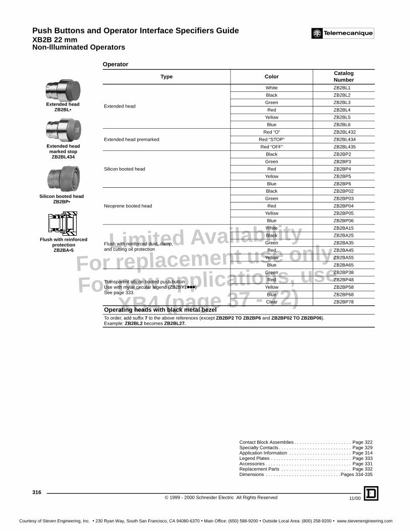
Push Buttons and Operator Interface Specifiers GuideXB2B 22 mmNon-Illuminated Operators
© 1999 - 2000 Schneider Electric All Rights Reserved316
11/00
Limited AvailabilityFor replacement use only.
For new applications, use XB4 (page 37 - 72)
Contact Block Assemblies . . . . . . . . . . . . . . . . . . . . . . Page 322Specialty Contacts . . . . . . . . . . . . . . . . . . . . . . . . . . . . Page 329Application Information . . . . . . . . . . . . . . . . . . . . . . . . Page 314Legend Plates . . . . . . . . . . . . . . . . . . . . . . . . . . . . . . . Page 333Accessories . . . . . . . . . . . . . . . . . . . . . . . . . . . . . . . . . Page 331Replacement Parts . . . . . . . . . . . . . . . . . . . . . . . . . . . Page 332Dimensions . . . . . . . . . . . . . . . . . . . . . . . . . . . . .Pages 334-335
Operator
Type ColorCatalogNumber
Extended head
White ZB2BL1
Black ZB2BL2
Green ZB2BL3
Red ZB2BL4
Yellow ZB2BL5
Blue ZB2BL6
Extended head premarked
Red “O” ZB2BL432
Red “STOP” ZB2BL434
Red “OFF” ZB2BL435
Silicon booted head
Black ZB2BP2
Green ZB2BP3
Red ZB2BP4
Yellow ZB2BP5
Blue ZB2BP6
Neoprene booted head
Black ZB2BP02
Green ZB2BP03
Red ZB2BP04
Yellow ZB2BP05
Blue ZB2BP06
Flush with reinforced dust, damp, and cutting oil protection
White ZB2BA15
Black ZB2BA25
Green ZB2BA35
Red ZB2BA45
Yellow ZB2BA55
Blue ZB2BA65
Transparent silicon booted push buttonUse with mylar circular legend (ZB2BY1kkk) See page 333.
Green ZB2BP38
Red ZB2BP48
Yellow ZB2BP58
Blue ZB2BP68
Clear ZB2BP78
Operating heads with black metal bezelTo order, add suffix 7 to the above references (except ZB2BP2 TO ZB2BP6 and ZB2BP02 TO ZB2BP06).Example: ZB2BL2 becomes ZB2BL27.
Extended headZB2BL•
Extended head marked stopZB2BL434
Silicon booted headZB2BP•
Flush with reinforced protectionZB2BA•5
Courtesy of Steven Engineering, Inc. ! 230 Ryan Way, South San Francisco, CA 94080-6370 ! Main Office: (650) 588-9200 ! Outside Local Area: (800) 258-9200 ! www.stevenengineering.com

Push Buttons and Operator Interface Specifiers GuideXB2B 22 mm
Mushroom Operators and Yellow Contrast Plates
31711/00 © 1999 - 2000 Schneider Electric All Rights Reserved
Limited AvailabilityFor replacement use only.
For new applications, use XB4 (page 37 - 72)
Yellow Contrast Plates
Contact Block Assemblies. . . . . . . . . . . . . . . . . . . . . . . . Page 322Specialty Contacts . . . . . . . . . . . . . . . . . . . . . . . . . . . . . Page 329Application Information . . . . . . . . . . . . . . . . . . . . . . . . . . Page 314Legend Plates . . . . . . . . . . . . . . . . . . . . . . . . . . . . . . . . . Page 333Accessories. . . . . . . . . . . . . . . . . . . . . . . . . . . . . . . . . . . Page 331Replacement Parts . . . . . . . . . . . . . . . . . . . . . . . . . . . . . Page 332Dimensions . . . . . . . . . . . . . . . . . . . . . . . . . . . . . . . Pages 334-335
Operator
Type Size ColorCatalogNumber
Mushroom headMomentary
30mm
Black ZB2BC24Green ZB2BC34
Red ZB2BC44Yellow ZB2BC54Blue ZB2BC64
40mm
Black ZB2BC2Green ZB2BC3Red ZB2BC4
Yellow ZB2BC5Blue ZB2BC6
60mm
Black ZB2BR2
Green ZB2BR3Red ZB2BR4
Yellow ZB2BR5
Blue ZB2BR6
Mushroom headKey releasea
40mm Red ZB2BS1460mm Red ZB2BS24
Mushroom head push buttonwith trigger actionfKey releasea
40mm Red ZB2BS944
Mushroom headturn to release 40mm Red ZB2BS54
Premarked “EMO” 40mm Red ZB2BS5430
Mushroom head push buttonwith trigger actionfTurn to release
40mm Red ZB2BS844
Mushroom headturn to release 60mm Red ZB2BS64
Mushroom headpush-pull 40mm
Black ZB2BT2
Red ZB2BT4Premarked “EMERGENCY STOP” 40mm Red ZB2BT43
Mushroom headpush-pull 60mm
Black ZB2BX2
Red ZB2BX4a Key release operators come with Ronis #455 keys (quantity 2) as standard. For replacement keys see page 332. For other key
numbers contact local field office.f Trigger action mushroom heads are “tamper proof” whereby a change of contact state is not possible by “teasing” or floating the
operator.
Guards / Locks
Type Size Color CatalogNumber
Metal 40 mm with finger cutout and 7 mm holes for padlocking Red ZB2BZ1804Plastic 60 mm (for 40 mm turn to release) Yellow ZB2BZ1905
PVC Yellow Legend Plates 60 mm diameter PVC Yellow Legend Plates 90 mm diameterText Language Catalog Number Text Language Catalog Number
Blank N/A ZB2BY9101 Blank N/A ZB2BY8101
Emergency Stop English ZB2BY9330 Emergency Stop English ZB2BY8330Arret d’Urgence French ZB2BY9130 Arret d’Urgence French ZB2BY8130Not Aus German ZB2BY9230 Not Aus German ZB2BY8230
Parada de Emergencia Spanish ZB2BY9430 Parada de Emergencia Spanish ZB2BY8430Arresto Emergenza Italian ZB2BY9630 Arresto Emergenza Italian ZB2BY8630
Mushroom head 40mmZB2BC•
Mushroom head 60mmZB2BR•
Mushroom headkey release
ZB2BS•4
Mushroom headturn to release
ZB2BS54
Mushroom headwith trigger action
turn to releaseZB2BS844
EMERGENCY
STOP
ZB2BY8330
Courtesy of Steven Engineering, Inc. ! 230 Ryan Way, South San Francisco, CA 94080-6370 ! Main Office: (650) 588-9200 ! Outside Local Area: (800) 258-9200 ! www.stevenengineering.com

Push Buttons and Operator Interface Specifiers GuideXB2B 22 mmLever and Key Operators
© 1999 - 2000 Schneider Electric All Rights Reserved318
11/00
Limited AvailabilityFor replacement use only.
For new applications, use XB4 (page 37 - 72)
a When ordering extended lever substitute J for D. Example: ZB2BD2 becomes ZB2BJ2.f Key selector switches come with Ronis #455 keys (quantity 2) as standard. For replacement keys see page 332. For switches
keyed with different keys, add the suffixes shown in the table below (no change in price). For other key numbers contact local field office.
Contact Block Assemblies . . . . . . . . . . . . . . . . . . . . Page 322Specialty Contacts . . . . . . . . . . . . . . . . . . . . . . . . . . Page 329Application Information . . . . . . . . . . . . . . . . . . . . . . . Page 314Legend Plates . . . . . . . . . . . . . . . . . . . . . . . . . . . . . . Page 333Accessories. . . . . . . . . . . . . . . . . . . . . . . . . . . . . . . . Page 331Replacement Parts . . . . . . . . . . . . . . . . . . . . . . . . . . Page 332Dimensions . . . . . . . . . . . . . . . . . . . . . . . . . . . . Pages 334-335
Lever OperatorsType Number of positions, actions Lever Color Catalog Number
Standard orExtended lever a
2-maintainedBlack ZB2BD2White ZB2BD201Red ZB2BD204
2-spring returnfrom right to left
Black ZB2BD4White ZB2BD401Red ZB2BD404
3-maintainedBlack ZB2BD3White ZB2BD301Red ZB2BD304
3-spring return to centerfrom left and right
Black ZB2BD5White ZB2BD501Red ZB2BD504
3-spring return fromright to center
Black ZB2BD8White ZB2BD801Red ZB2BD804
3-spring return fromleft to center
Black ZB2BD7White ZB2BD701Red ZB2BD704
Key OperatorsType Number of positions, actions, key removal Catalog Number
Key switchf
2-maintained key removal from left ZB2BG22-maintained key removal from left or right ZB2BG42-spring return from right to left, key removal from left ZB2BG63-maintained key removal from center ZB2BG33-maintained key removal from left and right ZB2BG53-maintained key removal from left ZB2BG93-maintained key removal from all positions ZB2BG03-spring return left or right to center, key removal from center ZB2BG73-spring return left to center key removal right ZB2BG13-spring return right to center key removal center ZB2BG83-spring return right to center key removal left ZB2BG08
Selector Switch Sequences (using contact block assemblies, page 322)2 Position selector switch 3 Position selector switch
Contact block guide
Contact block guide
O X 1 N.O. (left or right) X O O 1 N.O. (left)X O 1 N.C. (left or right) O X O 2 NC wired in series (side-by-side)O X 1 N.O. O O X 1 N.O. (right)
and X X O 1 N.C. (right)X O 1 N.C. O X X 1 N.C. (left)
Note: View from front of panel X O X 2 NO wired in parallel (side-by-side)
Operating heads with black metal bezelTo order, add suffix 7 to the above references.Example: ZB2BD3 becomes ZB2BD37.
Key Number Suffix421 12
458A 10520 14
3131A 20
Standard leverZB2BD•••
Extended leveraZB2BJ•••
Key switchZB2BG••
Courtesy of Steven Engineering, Inc. ! 230 Ryan Way, South San Francisco, CA 94080-6370 ! Main Office: (650) 588-9200 ! Outside Local Area: (800) 258-9200 ! www.stevenengineering.com

Push Buttons and Operator Interface Specifiers GuideXB2B 22 mm
Two Button Operators
31911/00 © 1999 - 2000 Schneider Electric All Rights Reserved
Limited AvailabilityFor replacement use only.
For new applications, use XB4 (page 37 - 72)
Contact Block Assemblies ........................................... Page 322Specialty Contacts ...................................................... Page 329Application Information ................................................ Page 314Legend Plates.............................................................. Page 333Accessories ................................................................. Page 331Replacement Parts ...................................................... Page 332Dimensions ......................................................... Pages 334-335
Momentary operators
Type Marked f ColorCatalogNumber
Two flush
Black/Red ZB2BA9124
Green/Red ZB2BA9134
I,O Black/Red ZB2BA9224
I,O Green/Red ZB2BA9234
STOP, START Black/Red ZB2BA9724
STOP, START Green/Red ZB2BA9734
One flush, one extended
Black/Red ZB2BL9324
Green/Red ZB2BL9334
I,O Black/Red ZB2BL9424
I,O Green/Red ZB2BL9434
STOP, START Black/Red ZB2BL9824
STOP, START Green/Red ZB2BL9834
f Additional markings available on special order. Contact local field office for details.
Operating heads with black metal bezelTo order, add suffix 7 to the above references.Example: ZB2BA9124 becomes ZB2BA91247.
2 Button maintained operators
TypeNumber ofcontact(s)
Button 1 Button 2CatalogNumber
Flush interlocked push buttons(30 mm centers, maintained,mechanically interlocked)Units include contact block(s) as shown.
1 NO-Black Black XB2BF521
1 NO-Black Red XB2BF551
1 NO-Green Red XB2BF581
2 NO-Black NO-Black XB2BF523
2 NO-Black NO-Red XB2BF553
2 NO-Green NO-Red XB2BF583
2 NO-Black NO-Black XB2BF525
2 NO-Black NC-Red XB2BF555
2 NO-Green NC-Red XB2BF585
Type ColorCatalogNumber
Replacement push button operators only(with no spring return in head)for XB2BF
Black ZB2BAW80424194002
Green ZB2BAW80424194003
Red ZB2BAW80424194004
Operating heads with black metal bezelTo order, add suffix 7 to the above references.Example: ZB2BF521 becomes ZB2BF5217.
Two flushZB2BA9•••
One flush, one extendedZB2BL94••
Start/stopZB2BL98••
InterlockedXB2BF5••
Courtesy of Steven Engineering, Inc. ! 230 Ryan Way, South San Francisco, CA 94080-6370 ! Main Office: (650) 588-9200 ! Outside Local Area: (800) 258-9200 ! www.stevenengineering.com

Push Buttons and Operator Interface Specifiers GuideXB2B 22 mmSpecialty Operators
© 1999 - 2000 Schneider Electric All Rights Reserved320
11/00
Limited AvailabilityFor replacement use only.
For new applications, use XB4 (page 37 - 72)
t Units come with 1 N.O. contact in each direction. Screw terminals. Contact blocks cannot be added or removed from the above arrangements. For other requirements, contact local sales office.
f Customer to supply potentiometer, unit accepts 1/4" diameter, 1.625" (43-47 mm) length shaft potentiometer.
These 2 direction and 4 direction position charts are viewed from behind the panel, thereby reversing east and west positions. When lever is moved away from center, only one contact changes from N.O. to N.C. The other contact blocks in the switch are unaffected.
Contact Block Assemblies . . . . . . . . . . . . . . . . . . . . . . . . Page 322Specialty Contacts . . . . . . . . . . . . . . . . . . . . . . . . . . . . . Page 329Application Information. . . . . . . . . . . . . . . . . . . . . . . . . . . Page 314Legend Plates . . . . . . . . . . . . . . . . . . . . . . . . . . . . . . . . . Page 333Accessories . . . . . . . . . . . . . . . . . . . . . . . . . . . . . . . . . . . Page 331Replacement Parts. . . . . . . . . . . . . . . . . . . . . . . . . . . . . . Page 332Dimensions. . . . . . . . . . . . . . . . . . . . . . . . . . . . . . . Pages 334-335
Operators
Type ColorCatalogNumber
Wobble sticksBlack ZB2BB2
Red ZB2BB4
Potentiometer operator f Black ZB2BD922
JoystickstContacts supplied
2-maintained XD2PA12
2-spring return XD2PA22
4-maintained XD2PA14
4-spring return XD2PA24
Two step push buttons (contacts supplied)
TypeContact1st step
Contact2nd step
CatalogNumber
Flush head
N.O. N.O. XB2BAk41
N.O. N.C. XB2BAk42
N.O.+N.C. N.O. XB2BAk43
N.O.+N.C. N.O.+N.C. XB2BAk44
k Replace k with desired color head. (1-white, 2-black, 3-green, 4-red, 5-yellow, 6-blue).
Two position toggle switch (maintained)
Type ColorCatalogNumber
Two position toggle switchNEMA Type 1 only Black ZB2BD28
Operating heads with black metal bezelTo order, add suffix 7 to the above references.Example: ZB2BD922 becomes ZB2BD9227.
Wobble sticks
Potentiometer operator
Joysticks
2 Position
OPERATED
CENTER
X
OPERATED
CENTER
X
4 Position
OPERATED
CENTER
X
OPERATED
CENTER
XO
PE
RAT
ED
CE
NT
ER
OP
ER
ATE
D
CE
NT
ER
X X
Courtesy of Steven Engineering, Inc. ! 230 Ryan Way, South San Francisco, CA 94080-6370 ! Main Office: (650) 588-9200 ! Outside Local Area: (800) 258-9200 ! www.stevenengineering.com

Push Buttons and Operator Interface Specifiers GuideXB2B 22 mm
Reset Operators
32111/00 © 1999 - 2000 Schneider Electric All Rights Reserved
Limited AvailabilityFor replacement use only.
For new applications, use XB4 (page 37 - 72)
Application Information . . . . . . . . . . . . . . . . . . . . . . . . . . Page 314Legend Plates . . . . . . . . . . . . . . . . . . . . . . . . . . . . . . . . . Page 333Dimensions . . . . . . . . . . . . . . . . . . . . . . . . . . . . . . . Pages 334-335
Reset operators
Type DescriptionAdjustable
length of rodColor
CatalogNumber
Flush head
0.39" (10 mm) TravelPanel thickness: 0.04" - 0.12" (1-3 mm)Tightened by nut
0.24" - 0.63"(6 - 16 mm)
Black XB2BA821
Red XB2BA841
Blue XB2BA861
0.63" - 1.02"(16 - 26 mm)
Black XB2BA822
Red XB2BA842
Blue XB2BA862
0.55" (14 mm) TravelPanel thickness: 0.04" - 0.23" (1-6 mm)Tightened by 2 screw mountingbase (supplied)
1.18" - 2.25"(30 - 57 mm)
Black XB2BA921
Red XB2BA941
Blue XB2BA961
2.16" - 3.23"(55 - 82 mm)
Black XB2BA922
Red XB2BA942
Blue XB2BA962
0.55" (14 mm) TravelPanel thickness: 0.04" - 0.23" (1-6 mm)Tightened by 2 screw mountingbase (supplied)
3.15" - 4.2"(80 - 107 mm)
Black XB2BA923
Red XB2BA943
Blue XB2BA963
4.13" - 5.2"(105 - 132 mm)
Black XB2BA924
Red XB2BA944
Blue XB2BA964
5.12"- 6.18"(130 - 157 mm)
Black XB2BA925
Red XB2BA945
Blue XB2BA965
6.1" - 7.16"(155 - 182 mm)
Black XB2BA926
Red XB2BA946
Blue XB2BA966
7.08" - 8.15"(180 - 207 mm)
Black XB2BA927
Red XB2BA947
Blue XB2BA967
8.07" - 9.13"(205 - 232 mm)
Black XB2BA928
Red XB2BA948
Blue XB2BA968
9.05" - 10.1"(230 - 257 mm)
Black XB2BA929
Red XB2BA949
Blue XB2BA969
Operating heads with black metal bezelTo order, add suffix 7 to the above references.Example: ZB2BA944 becomes ZB2BA9447.
XB2BA8kk
XB2BA9kk80 to 257 mm
XB2BA9kk30 to 82 mm
Courtesy of Steven Engineering, Inc. ! 230 Ryan Way, South San Francisco, CA 94080-6370 ! Main Office: (650) 588-9200 ! Outside Local Area: (800) 258-9200 ! www.stevenengineering.com

Push Buttons and Operator Interface Specifiers GuideXB2B 22 mmContact Blocks
© 1999 - 2000 Schneider Electric All Rights Reserved322
11/00
Limited AvailabilityFor replacement use only.
For new applications, use XB4 (page 37 - 72)
t Quick connect contact blocks will accept commercially available female quick slide connector (1 x 0.25" or 2 x 0.11")f Non-illuminated devices can be configured with 6 contacts maximum (3 decks of 2). ■ N.C. contact is direct opening operation conforming to EN 60 947-5-1, Section 3.
Non-Illuminated Operators. . . . . . . . . . . . . . . . . . . Pages 315-317Specialty Contacts . . . . . . . . . . . . . . . . . . . . . . . . . . . . . Page 329Application Information . . . . . . . . . . . . . . . . . . . . . . . . . .Page 314Accessories . . . . . . . . . . . . . . . . . . . . . . . . . . . . . . . . . . .Page 331Replacement Parts . . . . . . . . . . . . . . . . . . . . . . . . . . . . .Page 332Dimensions . . . . . . . . . . . . . . . . . . . . . . . . . . . . . . Pages 334-335
Mounting base with contact block(s) “Screw clamp connection”
N.O. N.C.
Type ContactsN.O. N.C. Catalog Number
1 Contact Block1 - ZB2BZ101
- 1 ZB2BZ102
2 Contact Blocks
2 - ZB2BZ103
- 2 ZB2BZ104
1 1 ZB2BZ105
Additional contact blocks
Type ContactsN.O. N.C. Catalog Number
For making up body assemblieswith 3, 4, 5 or max. of 6 contact blocksor replacing 1st or 2nd contact blockf
1 - ZB2BE101
- 1 ZB2BE102
Mounting base with contact block(s) “Quick connect” t
TypeContacts
N.O. N.C.Catalog Number
1 Contact Block1 - ZB2BZ1013
- 1 ZB2BZ1023
2 Contact Blocks
2 - ZB2BZ1033
- 2 ZB2BZ1043
1 1 ZB2BZ1053
Additional contact blocks “Quick Connect” *
TypeContacts
N.O. N.C.Catalog Number
For making up body assemblieswith 3, 4, 5 or max. of 6 contact blocksor replacing 1st or 2nd contact blockf
1 - ZB2BE1013
- 1 ZB2BE1023
Spare partsDescription Catalog Number
Mounting Base only With fixing screws ZB2BZ009
Quick Connect t Fitting by customer ZB2BZ003
ZB2BZ101
ZB2BE10k
■
■
ZB2BZ009
Courtesy of Steven Engineering, Inc. ! 230 Ryan Way, South San Francisco, CA 94080-6370 ! Main Office: (650) 588-9200 ! Outside Local Area: (800) 258-9200 ! www.stevenengineering.com

Push Buttons and Operator Interface Specifiers GuideXB2B 22 mm
Pilot Lights and Light Modules
32311/00 © 1999 - 2000 Schneider Electric All Rights Reserved
Limited AvailabilityFor replacement use only.
For new applications, use XB4 (page 37 - 72)
t Complete catalog number by adding one of the following voltages: 6, 12, 24, 48 or 120 V. If desired without bulb, omit voltage.f Light module assemblies are available with quick connectors. Add suffix “3” to end of part number.
Example: ZB2BV6 becomes ZB2BV63.
Replacement Bulbs . . . . . . . . . . . . . . . . . . . . . . . . . . . Page 332Application Information. . . . . . . . . . . . . . . . . . . . . . . . . Page 314Accessories . . . . . . . . . . . . . . . . . . . . . . . . . . . . . . . . . Page 331Replacement Parts. . . . . . . . . . . . . . . . . . . . . . . . . . . . Page 332Dimensions . . . . . . . . . . . . . . . . . . . . . . . . . . . . .Pages 334-335
Pilot light heads
Type ColorCatalogNumber
Standard
White ZB2BV01
Green ZB2BV03
Red ZB2BV04
Amber ZB2BV05
Blue ZB2BV06
Clear ZB2BV07
Special lens for neon and LED bulbs
Green ZB2BV033
Red ZB2BV043
Amber ZB2BV053
Blue ZB2BV063
Clear ZB2BV073
Glass lens (NEMA Type 1 only)
Green ZB2BV032
Red ZB2BV042
Amber ZB2BV052
Clear ZB2BV072
Pilot light modules f
TypeCatalogNumber
Direct supply (incandescent bulb included)t (AC/DC) ZB2BV6t
Transformer type (1.2 VA/6 V bulb included) (AC only)
24 V: 50-60 Hz ZB2BV1
48 V: 50-60 Hz ZB2BV2
110 V: 50 Hz 110-120 V: 60 Hz ZB2BV3
127 V: 50 Hz ZB2BV91
220 V: 50 Hz ZB2BV4
240 V: 50 Hz 220-240 V: 60 Hz ZB2BV94
380 V: 50 Hz ZB2BV5
415 V: 50 Hz ZB2BV9
440-480 V: 60 Hz ZB2BV95
500 V: 50 Hz ZB2BV8
550-660 V: 60 Hz ZB2BV98
Resistor type (130 V bulb included).
220/250 V (AC/DC) ZB2BV7
StandardZB2BV••
Special lens for neon and LED bulbsZB2BV0••
Direct supplyZB2BV6
Transformer typeZB2BV3
Courtesy of Steven Engineering, Inc. ! 230 Ryan Way, South San Francisco, CA 94080-6370 ! Main Office: (650) 588-9200 ! Outside Local Area: (800) 258-9200 ! www.stevenengineering.com

Push Buttons and Operator Interface Specifiers GuideXB2B 22 mmIlluminated Operators
© 1999 - 2000 Schneider Electric All Rights Reserved324
11/00
Limited AvailabilityFor replacement use only.
For new applications, use XB4 (page 37 - 72)
Light Module Assemblies . . . . . . . . . . . . . . . . . . . . . . . . . . Page 328Specialty Light Modules . . . . . . . . . . . . . . . . . . . . . . . . . . . Page 330Application Information . . . . . . . . . . . . . . . . . . . . . . . . . . . . Page 314Legend Plates. . . . . . . . . . . . . . . . . . . . . . . . . . . . . . . . . . . Page 333Accessories . . . . . . . . . . . . . . . . . . . . . . . . . . . . . . . . . . . . Page 331Replacement Parts . . . . . . . . . . . . . . . . . . . . . . . . . . . . . . . Page 332Dimensions. . . . . . . . . . . . . . . . . . . . . . . . . . . . . . . . .Pages 334-335
Operator
Type ColorCatalog Number
Flush head White ZB2BW31
Green ZB2BW33
Red ZB2BW34
Amber ZB2BW35
Blue ZB2BW36
Clear ZB2BW37
Flush head for neon and LED lamps Green ZB2BW333
Red ZB2BW343
Amber ZB2BW353
Blue ZB2BW363
Clear ZB2BW373
Extended head White ZB2BW11
Green ZB2BW13
Red ZB2BW14
Amber ZB2BW15
Blue ZB2BW16
Clear ZB2BW17
Extended head for neon and LED lamps Green ZB2BW133
Red ZB2BW143
Amber ZB2BW153
Blue ZB2BW163
Clear ZB2BW173
Silicon booted flush head Green ZB2BW53
Use with mylar circular legend (ZB2BY1kkk) Red ZB2BW54
See page 333 Amber ZB2BW55
Blue ZB2BW56
Clear ZB2BW57
Push to test Green ZB2BV031
Red ZB2BV041
Amber ZB2BV051
Blue ZB2BV061
Clear ZB2BV071
Operating heads with black metal bezelTo order, add suffix 7 to the above references.Example: ZB2BV071 becomes ZB2BV0717.
Flush HeadZB2BW3•
Flush Head for LEDZB2BW3••
Extended HeadZB2BW1•
Extended Head for LEDZB2BW1••
Silicon Booted Flush HeadZB2BW5•
Courtesy of Steven Engineering, Inc. ! 230 Ryan Way, South San Francisco, CA 94080-6370 ! Main Office: (650) 588-9200 ! Outside Local Area: (800) 258-9200 ! www.stevenengineering.com

Push Buttons and Operator Interface Specifiers GuideXB2B 22 mm
Illuminated Operators
32511/00 © 1999 - 2000 Schneider Electric All Rights Reserved
Limited AvailabilityFor replacement use only.
For new applications, use XB4 (page 37 - 72)
t Additional color indicators available, contact local field office for details.f To upgrade to NEMA Type 3, 4, 13 order clear silicon boot ZB2BW008.
Light Module Assemblies ............................................... Page 328Specialty Light Modules ................................................. Page 330Application Information .................................................. Page 314Legend Plates ................................................................ Page 333Accessories.................................................................... Page 331Replacement Parts ........................................................ Page 332Dimensions ........................................................... Pages 334-335
Mushroom operator
Type Color CatalogNumber
40 mm Mushroom head Green ZB2BW43
2 position momentary Red ZB2BW44
Amber ZB2BW45
Blue ZB2BW46
Clear ZB2BW47
40 mm Mushroom head Green ZB2BW63
2 position maintained Red ZB2BW64
Amber ZB2BW65
Blue ZB2BW66
Clear ZB2BW67
Two button with amber indicatort NEMA Type 1 onlyf
Type Marked Color CatalogNumber
Two Flush Black/Red ZB2BW81254
Green/Red ZB2BW81354
I,O Black/Red ZB2BW82254
I,O Green/Red ZB2BW82354
START,STOP Black/Red ZB2BW87254
START,STOP Green/Red ZB2BW87354
One flush, one extended Black/Red ZB2BW83254
Green/Red ZB2BW83354
I,O Black/Red ZB2BW84254
I,O Green/Red ZB2BW84354
START,STOP Black/Red ZB2BW88254
START,STOP Green/Red ZB2BW88354
Operating heads with black metal bezelTo order, add suffix 7 to the above references.Example: ZB2BW64 becomes ZB2BW647.
40 mm Mushroom headZB2BW••
Two FlushAmber Indicator
ZB2BW8••54
Courtesy of Steven Engineering, Inc. ! 230 Ryan Way, South San Francisco, CA 94080-6370 ! Main Office: (650) 588-9200 ! Outside Local Area: (800) 258-9200 ! www.stevenengineering.com

Push Buttons and Operator Interface Specifiers GuideXB2B 22 mmIlluminated Operators
© 1999 - 2000 Schneider Electric All Rights Reserved326
11/00
Limited AvailabilityFor replacement use only.
For new applications, use XB4 (page 37 - 72)
Light Module Assemblies...................................................... Page 328Specialty Light Modules........................................................ Page 330Application Information ......................................................... Page 314Legend Plates....................................................................... Page 333Accessories .......................................................................... Page 331Dimensions.................................................................. Pages 334-335
Selector Switches
Number of positions, action ColorCatalogNumber
2-maintained Green ZB2BK123
Red ZB2BK124
Amber ZB2BK125
Blue ZB2BK126
Clear ZB2BK127
2-spring return Green ZB2BK143
from right to left Red ZB2BK144
Amber ZB2BK145
Blue ZB2BK146
Clear ZB2BK147
3-maintained Green ZB2BK133
Red ZB2BK134
Amber ZB2BK135
Blue ZB2BK136
Clear ZB2BK137
3-spring return to Green ZB2BK153
center from right and left Red ZB2BK154
Amber ZB2BK155
Blue ZB2BK156
Clear ZB2BK157
3-spring return Green ZB2BK183
from right to center Red ZB2BK184
Amber ZB2BK185
Blue ZB2BK186
Clear ZB2BK187
3-spring return Green ZB2BK173
from left to center Red ZB2BK174
Amber ZB2BK175
Blue ZB2BK176
Clear ZB2BK177
Selector Switch Sequences (using contact block assemblies, page 328)2 Position selector switch 3 Position selector switch
Contact block guide
Contact block guide
O X 1 N.O. (left or right) X O O 1 N.O. (left)X O 1 N.C. (left or right) O X O 2 NC wired in series (side-by-side)O X 1 N.O. O O X 1 N.O. (right)
and X X O 1 N.C. (right)X O 1 N.C. O X X 1 N.C. (left)
Note: View from front of panel X O X 2 NO wired in parallel (side-by-side)
Operating heads with black metal bezelTo order, add suffix 7 to the above references.Example: ZB2BK123 becomes ZB2BK1237.
Selector switchZB2BK1kk
Courtesy of Steven Engineering, Inc. ! 230 Ryan Way, South San Francisco, CA 94080-6370 ! Main Office: (650) 588-9200 ! Outside Local Area: (800) 258-9200 ! www.stevenengineering.com

Push Buttons and Operator Interface Specifiers GuideXB2B 22 mm
Illuminated Operators
32711/00 © 1999 - 2000 Schneider Electric All Rights Reserved
Limited AvailabilityFor replacement use only.
For new applications, use XB4 (page 37 - 72)
Application Information. . . . . . . . . . . . . . . . . . . . . . . Page 314Legend Plates . . . . . . . . . . . . . . . . . . . . . . . . . . . . . Page 333Accessories . . . . . . . . . . . . . . . . . . . . . . . . . . . . . . . Page 331Replacement Parts. . . . . . . . . . . . . . . . . . . . . . . . . . Page 332Dimensions . . . . . . . . . . . . . . . . . . . . . . . . . . . Pages 334-335
40 mm Mushroom head
Type Pushpositiont Color Catalog Number
1N.O. - 1N.C.♦
Catalog Number2N.O. - 2N.C.
Non-illuminatedM: MaintainedSR: Spring Return
M White XB2BN111 XB2BN112M Green XB2BN311 XB2BN312M Red XB2BN411 XB2BN412M Amber XB2BN511 XB2BN512M Blue XB2BN611 XB2BN612M Clear XB2BN711 XB2BN712SR White XB2BN121 XB2BN122SR Green XB2BN321 XB2BN322SR Red XB2BN421 XB2BN422SR Amber XB2BN521 XB2BN522SR Blue XB2BN621 XB2BN622SR Clear XB2BN721 XB2BN722
IlluminatedDirect supply
M White XB2BN1161 XB2BN1162M Green XB2BN3161 XB2BN3162M Red XB2BN4161 XB2BN4162M Amber XB2BN5161 XB2BN5162M Blue XB2BN6161 XB2BN6162M Clear XB2BN7161 XB2BN7162SR White XB2BN1261 XB2BN1262SR Green XB2BN3261 XB2BN3262SR Red XB2BN4261 XB2BN4262SR Amber XB2BN5261 XB2BN5262SR Blue XB2BN6261 XB2BN6262SR Clear XB2BN7261 XB2BN7262
IlluminatedTransformer Type 110/120 V(lamp included)
M White XB2BN1131 XB2BN1132M Green XB2BN3131 XB2BN3132M Red XB2BN4131 XB2BN4132M Amber XB2BN5131 XB2BN5132M Blue XB2BN6131 XB2BN6132M Clear XB2BN7131 XB2BN7132SR White XB2BN1231 XB2BN1232SR Green XB2BN3231 XB2BN3232SR Red XB2BN4231 XB2BN4232SR Amber XB2BN5231 XB2BN5232SR Blue XB2BN6231 XB2BN6232SR Clear XB2BN7231 XB2BN7232
IlluminatedTransformer Type220/240V(lamp included)
M White XB2BN1141 XB2BN1142M Green XB2BN3141 XB2BN3142M Red XB2BN4141 XB2BN4142M Amber XB2BN5141 XB2BN5142M Blue XB2BN6141 XB2BN6142M Clear XB2BN7141 XB2BN7142SR White XB2BN1241 XB2BN1242SR Green XB2BN3241 XB2BN3242SR Red XB2BN4241 XB2BN4242SR Amber XB2BN5241 XB2BN5242SR Blue XB2BN6241 XB2BN6242SR Clear XB2BN7241 XB2BN7242
Mushroom lens only
White W40429264001Green W40429264003Red W40429264004
Amber W40429264005Blue W40429264006Clear W40429264007
t Position status: Position 1 - Pull. Spring return, Position 2- Center, Maintained, Position 3 - Push. Maintained or spring return. f Contacts cannot be modified or interchanged; therefore operators are not sold separately.
1 N.O./1 N.C. 2 N.O./2 N.C.Pos. 1
PullPos. 2Center
Pos. 3Push
Pos. 1Pull
Pos. 2Center
Pos. 3Push
Non-IlluminatedXB2BN•••
Illuminated(Direct Supply)
XB2BN••6•
Illuminated(Transformer type)
XB2BN••••
Courtesy of Steven Engineering, Inc. ! 230 Ryan Way, South San Francisco, CA 94080-6370 ! Main Office: (650) 588-9200 ! Outside Local Area: (800) 258-9200 ! www.stevenengineering.com

Push Buttons and Operator Interface Specifiers GuideXB2B 22 mmLight Module Assemblies
© 1999 - 2000 Schneider Electric All Rights Reserved328
11/00
Limited AvailabilityFor replacement use only.
For new applications, use XB4 (page 37 - 72)
+ Complete catalog number by adding one of the following voltages: 6, 12, 24, 48 or 120 V AC/DC.Note: If desired without bulb, omit voltage.
t Select proper digit for voltage desired: 1 (24 V 50/60 Hz) 2(48 V 50/60 Hz) 3 (110/120 V 50/60 Hz).94 (220/240 V 60 Hz) 95 (440/480 V 60 Hz) 98 (550/600 V 60 Hz).
f Illuminated devices can be configured with a light module and 4 contacts maximum (2 decks of 2).j Additional primary voltages available, contact local field office for details.k Contact blocks and light module assemblies are available with quick connectors. Add suffix “3” to end of part number.
Example: ZB2BW061 becomes ZB2BW0613.■ N.C. contact is direct opening operation conforming to EN 60 947-5-1, Section 3.
Illuminated Operators . . . . . . . . . . . . . . . . . . . . . . . . .Pages 324-326Specialty Light Modules. . . . . . . . . . . . . . . . . . . . . . . . . . . . Page 330Application Information . . . . . . . . . . . . . . . . . . . . . . . . . . . . Page 314Legend Plates . . . . . . . . . . . . . . . . . . . . . . . . . . . . . . . . . . . Page 333Accessories . . . . . . . . . . . . . . . . . . . . . . . . . . . . . . . . . . . . . Page 331Replacement Parts . . . . . . . . . . . . . . . . . . . . . . . . . . . . . . . Page 332Dimensions . . . . . . . . . . . . . . . . . . . . . . . . . . . . . . . . .Pages 334-335
Light module assemblies with contact block(s) N.O. N.C.screw clamp connectorsk
Type Contacts Catalog
NumberN.O. N.C.
Direct supply (incandescent bulb included) (AC/DC)
Without contactsf - - ZB2BW060+
1 Contact block 1 - ZB2BW061+
- 1 ZB2BW062+
2 Contact blocks 2 - ZB2BW063+
- 2 ZB2BW064+
1 1 ZB2BW065+
Transformer type (1.2 VA/6 V AC incandescent bulb included) (AC only)j
Without contactsf - - ZB2BW0t0
1 Contact block 1 - ZB2BW0t1
- 1 ZB2BW0t2
2 Contact blocks 2 - ZB2BW0t3
- 2 ZB2BW0t4
1 1 ZB2BW0t5
Resistor type (130 V incandescent bulb included) 220-250 V supply
2 Contact blocks 1 1 ZB2BW075
Additional contact blocks f ■ N.O. N.C.
TypeContacts Catalog
NumberN.O. N.C.For making up body assemblieswith 3 or maximum 4 contact blocksor replacing 1st or 2nd contact block
1 - ZB2BE101
- 1 ZB2BE102
Direct supplyZB2BW06k
Transformer typeZB2BW03k
Resistor typeZB2BW075
Additional contact blockZB2BE10k
■
Courtesy of Steven Engineering, Inc. ! 230 Ryan Way, South San Francisco, CA 94080-6370 ! Main Office: (650) 588-9200 ! Outside Local Area: (800) 258-9200 ! www.stevenengineering.com
Push Buttons and Operator Interface Specifiers GuideXB2B 22 mm
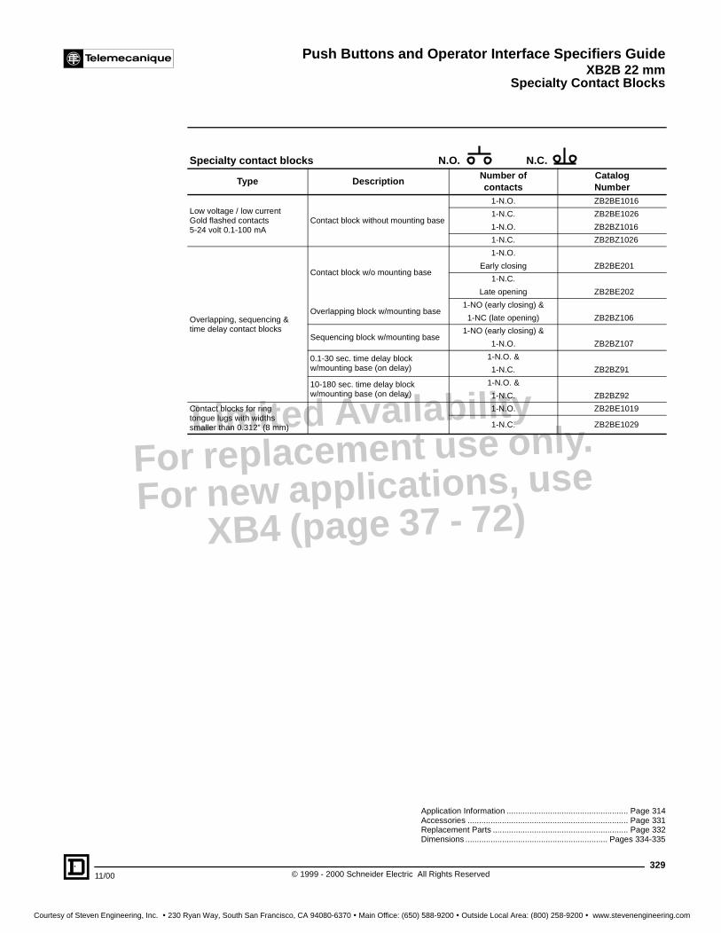
Specialty Contact Blocks
32911/00 © 1999 - 2000 Schneider Electric All Rights Reserved
Limited AvailabilityFor replacement use only.
For new applications, use XB4 (page 37 - 72)
Application Information ..................................................... Page 314Accessories ...................................................................... Page 331Replacement Parts ........................................................... Page 332Dimensions .............................................................. Pages 334-335
Specialty contact blocks N.O. N.C.
Type DescriptionNumber ofcontacts
CatalogNumber
Low voltage / low currentGold flashed contacts5-24 volt 0.1-100 mA
Contact block without mounting base
1-N.O. ZB2BE1016
1-N.C. ZB2BE1026
1-N.O. ZB2BZ1016
1-N.C. ZB2BZ1026
Overlapping, sequencing &time delay contact blocks
Contact block w/o mounting base
1-N.O.
Early closing ZB2BE201
1-N.C.
Late opening ZB2BE202
Overlapping block w/mounting base1-NO (early closing) &
1-NC (late opening) ZB2BZ106
Sequencing block w/mounting base1-NO (early closing) &
1-N.O. ZB2BZ107
0.1-30 sec. time delay block w/mounting base (on delay)
1-N.O. &
1-N.C. ZB2BZ91
10-180 sec. time delay block w/mounting base (on delay)
1-N.O. &
1-N.C. ZB2BZ92
Contact blocks for ringtongue lugs with widths smaller than 0.312” (8 mm)
1-N.O. ZB2BE1019
1-N.C. ZB2BE1029
Courtesy of Steven Engineering, Inc. ! 230 Ryan Way, South San Francisco, CA 94080-6370 ! Main Office: (650) 588-9200 ! Outside Local Area: (800) 258-9200 ! www.stevenengineering.com

Push Buttons and Operator Interface Specifiers GuideXB2B 22 mmSpecialty Light Modules
© 1999 - 2000 Schneider Electric All Rights Reserved330
11/00
Limited AvailabilityFor replacement use only.
For new applications, use XB4 (page 37 - 72)
c When ordering, specify voltage required (6-120 V) Example: ZB2BV156120V
Illuminated Operators . . . . . . . . . . . . . . . . . . . . . . .Pages 324-326Application Information . . . . . . . . . . . . . . . . . . . . . . . . . . Page 314Legend Plates. . . . . . . . . . . . . . . . . . . . . . . . . . . . . . . . . Page 333Accessories . . . . . . . . . . . . . . . . . . . . . . . . . . . . . . . . . . Page 331Replacement Parts . . . . . . . . . . . . . . . . . . . . . . . . . . . . . Page 332Dimensions . . . . . . . . . . . . . . . . . . . . . . . . . . . . . . .Pages 334-335
Specialty Light ModulesType Description Supply Voltage Catalog Number
Flashing pilot light base Light Module with incandescent bulb included 120 Vac ZB2BV184
Flashing illuminated push button base Light Module with incandescent bulb and 1 N.O./1 N.C. included
120 Vac ZB2BW1845
Typical Wiring Diagrams
Type Description Supply Voltage Catalog Number
Remote test pilot light base Single Diode <380 V ac or dc
ZB2BV156c
Typical Wiring Diagram – Single Diode
Type Description Supply Voltage Catalog Number
Remote test pilot light base Dual Diode <380 Vac or dc
ZB2BV68
Typical Wiring Diagram – Dual Diode
Flashing pilot light baseZB2BV184
X1 Y1
X2 Y2
X1 Y1
X2 Y2
X1 Y1
X2 Y2
X1 Y1
X2 Y2
X1 Y1
X2 Y2
X1 Y1
X2 Y2
Off Flashing On Wiring in parallel
-X1,+X2
Remote testpilot light base
ZB2BV156
Test X1 X2
Test
X1
X2
M
Courtesy of Steven Engineering, Inc. ! 230 Ryan Way, South San Francisco, CA 94080-6370 ! Main Office: (650) 588-9200 ! Outside Local Area: (800) 258-9200 ! www.stevenengineering.com

Push Buttons and Operator Interface Specifiers GuideXB2B 22 mm
Accessories and Replacement Parts
33111/00 © 1999 - 2000 Schneider Electric All Rights Reserved
Limited AvailabilityFor replacement use only.
For new applications, use XB4 (page 37 - 72)
XB2B Accessories
Type DescriptionCatalogNumber
BootsSilicon boot for rectangular push button w/indicator light ZB2BW008
Silicon boot for rectangular push button w/o light ZB2BA008
Guards/Locks
40 mm for Momentary Mushrooms (metal)
Blue ZB2BZ1601
Black ZB2BZ1602
Red ZB2BZ1604
Yellow ZB2BZ1605
40 mm with finger cut-out for push-pull (metal)
Blue ZB2BZ1701
Black ZB2BZ1702
Red ZB2BZ1704
Yellow ZB2BZ1705
40 mm with finger cut-out and 7mm holes for padlocking (metal)
Blue ZB2BZ1801
Black ZB2BZ1802
Red ZB2BZ1804
Yellow ZB2BZ1805
60 mm mushroom guard (black plastic)no padlocking provision
ZB2BZ19
60 mm guard for 40 mm T-T-R EMO button (yellow plastic) ZB2BZ1905
Padlock attachment(makes flush operator inaccessible)
ZB2BZ6
Closing plates22 mm
Black plastic ZB2SZ3
Gray plastic ZB2 SZ4
Blue metallic ZB2SZ2
Miscellaneousaccessories
Adapter for mounting into 1 3/16" (30 mm) holeand used with 30 mm P.B. nameplate ZB2BZ41
Adapter for mounting into 30 mm hole and use withXB2B nameplate ZB2BZ4
Base only-for mounting contact blocks ZB2BZ009
Add on push-on/push-off mechanism ZB2BZ21
Bulb extractor for use with BA9s XBFX13
ZB2BZ16kk
ZB2BZ18kk
ZB2BZ17kk
ZB2SZ3
ZB2BZ21
Courtesy of Steven Engineering, Inc. ! 230 Ryan Way, South San Francisco, CA 94080-6370 ! Main Office: (650) 588-9200 ! Outside Local Area: (800) 258-9200 ! www.stevenengineering.com

Push Buttons and Operator Interface Specifiers GuideXB2B 22 mmAccessories and Replacement Parts
© 1999 - 2000 Schneider Electric All Rights Reserved332
11/00
Limited AvailabilityFor replacement use only.
For new applications, use XB4 (page 37 - 72)
k Complete lens part number by replacing with digit for desired color. (1- white, 3- green, 4-red, 5- amber, 6- blue, 7-clear). Example ZB2BV013 green standard pilot lens. Note: Jeweled lens not available in white.
j Complete boot part number by replacing with digit for desired color. (2- black, 3- green, 4- red, 5- yellow, 6- blue, 7-clear).Example ZB2BP013 green silicon boot.
Lamps
Type Voltage AC/DC Watts Catalog Number
IncandescentReplacement bulbs (Type BA9s)
6 1.5 DL1CB006
12 2.0 DL1CE012
24 2.0 DL1CE024
48 2.4 DL1CE048
130 2.6 DL1CE130
Neon(use with direct supply light module)
120 - NE51HRT120V
220 - NE51HRT220V
380 - NE51HRT380V
Type Color Voltage Part Number
LED, BA9s base for Direct Supply blocks
Green 6 Vac/dc DL1CJUS0063
Red 6 Vac/dc DL1CJUS0064
Amber 6 Vac/dc DL1CJUS0065
Green 12 Vac/dc DL1CJUS0123
Red 12 Vac/dc DL1CJUS0124
Amber 12 Vac/dc DL1CJUS0125
Green 24 Vac/dc DL1CJUS0243
Red 24 Vac/dc DL1CJUS0244
Amber 24 Vac/dc DL1CJUS0245
Green 120 Vac/dc DL1CJUS1203
Red 120 Vac/dc DL1CJUS1204
Amber 120 Vac/dc DL1CJUS1205
LED, BA9s base for retrofitting into transformer Light Modules
Green 9 Vac only DL1CJUS0093
Red 9 Vac only DL1CJUS0094
Amber 9 Vac only DL1CJUS0095
Replacement Lenses, Boots and Keys
Type Description Catalog Number
Replacement lenses
Lens - standard pilot light ZB2BV01k
Lens kit - standard pilot light(includes lens, diffuser & gasket) ZB2BV02k
Lens - pilot light(jeweled for LED & Neon) ZB2BV01k3
Lens - flush illuminated push buttons ZB2BW91k
Lens - flush illuminated push buttons(Jeweled for LED & Neon) ZB2BW93k3
Lens - extended push buttons ZB2BW93k
Lens - extended push buttons(jeweled for LED & Neon) ZB2BW93k3
Lens - push-to-test ZB2BV01k1
Lens - rectangle for ZB2BW80000 series(2 button with indicator) ZB2BW90k
Lens - 40 mm mushroom W4042926400k
Replacement boots
Replacement silicon boot for ZB2BPseries operators ZB2BP01j
Replacement neoprene boot for ZB2BPseries operators ZB2BP02j
Replacement keys
Replacement key for standard selector switches and key release mushroom operators. Qty. 1 - Ronis key #455 Q99900901
Key # 421 Qty. 1 Q99900911
Key # 458A Qty. 1 Q99900910
Key # 520 Qty. 1 Q99900912
Key # 3131A Qty. 1 Q99900915
DL1CE• • •(incandescent)
DL1CJUS• • •(LED)
ZB2-BVZB2BVkkk
ZB2-BW93.ZB2BW93k
ZB2 BP012ZB2BP012
Q99900901Q99900901
Courtesy of Steven Engineering, Inc. ! 230 Ryan Way, South San Francisco, CA 94080-6370 ! Main Office: (650) 588-9200 ! Outside Local Area: (800) 258-9200 ! www.stevenengineering.com

Push Buttons and Operator Interface Specifiers GuideXB2B 22 mm
Legend Plates
33311/00 © 1999 - 2000 Schneider Electric All Rights Reserved
Limited AvailabilityFor replacement use only.
For new applications, use XB4 (page 37 - 72)
a All nameplates are black w/white lettering except “Stop”, “Emergency Stop” and “Reset” which are red w/white lettering.For black “Reset” change final digit of catalog number to 2.
j Please specify lettering when ordering. Two lines with 11 characters (including spaces) maximum on each line.
PVC Standard legend plates 30 x 40 mmTexta Catalog Number Texta Catalog Number
Close ZB2BY2314 On ZB2BY2311Down ZB2BY2308 Off On ZB2BY2367Emergency Stop ZB2BY2330 Open ZB2BY2313
Fast ZB2BY2328 Open Close ZB2BY2376Forward ZB2BY2305 Open-O-Close ZB2BY2388For Rev ZB2BY2371 Out ZB2BY2339
For-O-Rev ZB2BY2384 Power On ZB2BY2326Hand Off Auto ZB2BY2387 Raise ZB2BY2335High ZB2BY2338 Reset ZB2BY2323
High Low ZB2BY2369 Reverse ZB2BY2306In ZB2BY2503 Right ZB2BY2309Inch ZB2BY2321 Run ZB2BY2334
Jog For ZB2BY2381 Slow ZB2BY2327Jog Rev ZB2BY2380 Start ZB2BY2303Jog Run ZB2BY2365 Stop ZB2BY2304
Left ZB2BY2310 Stop Start ZB2BY2366Low ZB2BY2336 Up ZB2BY2307Lower ZB2BY2337 Up Down ZB2BY2370
Man-Auto ZB2BY2372 Up-O-Down ZB2BY2389Off ZB2BY2312
PVC Yellow Legend Plates 60 mm diameter PVC Yellow Legend Plates 90 mm diameterText Language Catalog Number Text Language Catalog Number
Blank N/A ZB2BY9101 Blank N/A ZB2BY8101Emergency Stop English ZB2BY9330 Emergency Stop English ZB2BY8330Arret d’Urgence French ZB2BY9130 Arret d’Urgence French ZB2BY8130Not Aus German ZB2BY9230 Not Aus German ZB2BY8230Parada de Emergencia Spanish ZB2BY9430 Parada de Emergencia Spanish ZB2BY8430Arresto Emergenza Italian ZB2BY9630 Arresto Emergenza Italian ZB2BY8630
Type Description Catalog Number
PVC blank legend
Blank Black or red background-30 mm x 40 mm ZB2BY2101Blank Yellow or white background-30 mm x 40 mm ZB2BY4101
Blank Red background-45 mm x 67.5 mm (For use w/mushroom head operators) ZB2BY5101
Blank Oversized legend-48 mm x 48 mm(For use with XB2 operators) XBCY22011
Blank Black or red background- 30 mm x 48 mm(For use w/2 position joysticks) ZD2GY2201
Metal legend plates
Silver 30 x 40 mm ZB2BY201130 x 50 mm ZB2BY6011
Black 30 x 40 mm ZB2BY202130 x 50 mm ZB2BY6021
Red 30 x 40 mm ZB2BY204130 x 50 mm ZB2BY6041
PVC custom engraved
Special engravingj Black background, white letters-30 mm x 40 mm ZB2BY2002Special engravingj Red background, white letters-30 mm x 40 mm ZB2BY2004Special engravingj White background, black letters-30 mm x 40 mm ZB2BY4001Special engravingj Yellow background, black letters-30 mm x 40 mm ZB2BY4005Special engravingj Red background, white letters-45 mm x 67.5 mm ZB2BY5004
Mylar Circular LegendsType Description Catalog Number
Mylar circularlegends for use withtransparent flushhead operatorsSee page 315, 324
No text ZB2BY1101O ZBZBY1146I ZBZBY1147Auto ZB2BY1115Hand ZB2BY1316Off ZB2BY1312On ZB2BY1311Start ZB2BY1303Stop ZB2BY1304Forward ZB2BY1305Reverse ZB2BY1306
EMERGENCY
STOP
ZB2BY8330
Courtesy of Steven Engineering, Inc. ! 230 Ryan Way, South San Francisco, CA 94080-6370 ! Main Office: (650) 588-9200 ! Outside Local Area: (800) 258-9200 ! www.stevenengineering.com

Push Buttons and Operator Interface Specifiers GuideXB2B 22 mm
© 1999 - 2000 Schneider Electric All Rights Reserved334
11/00
DimensionsZB2BA•ZB2BA•8ZB2BA•9ZB2BW3•
.4712
1.14 29 1.14 29
.6717
ZB2BA•6
1.14 29
.7920
ZB2BL•ZB2BW1•
.8722
1.18 30
ZB2BH•
1.14 29
.5915
ZB2BP•ZB2BW5•
1.57 40
1.2632
ZB2BC•ZB2BT•ZB2BS54ZB2BW4•
2.36 60
1.3434
ZB2BR•ZB2BX•ZB2BS64
1.57 40
1.2532
.9424
ZB2BS14
2.36 60
1.3434
.9123
ZB2BS24
1.0627
1.54 39
ZB2BJ•••
1.14 29
.9123
.8321
ZB2BG•
1.14 29
.5514
ZB2BVO•ZB2BVO•3
1.14 29
.7519
ZB2BVO•1
1.18 30
.9825
ZB2BVO•2
1.14 29
1.4637
.6316
ZB2BD922
1.1830
1.79
42.5
.4311
ZB2BA91•4
.5915
ZB2 BL93•4
2.17 55
1.1830
.4311
ZB2BW81•••
.5915
ZB2BW83•••
.98
Maximum travel = 25mm in all directions
3.4688
1.14 2922
ZB2BB•
1.57 40
1.8547
ZB2BS844
1.57 40
1.8547
.9424
ZB2BS944
1.14 29
1.0627
ZB2BD•••ZB2BK1•••
Dual Dimensions inchesmm
Courtesy of Steven Engineering, Inc. ! 230 Ryan Way, South San Francisco, CA 94080-6370 ! Main Office: (650) 588-9200 ! Outside Local Area: (800) 258-9200 ! www.stevenengineering.com

Push Buttons and Operator Interface Specifiers GuideXB2B 22 mm
33511/00 © 1999 - 2000 Schneider Electric All Rights Reserved
Dimensions
2.36 60
1.77
45
0.47
12
dia.
1.14
29
cent
ers
1.18 30
XB2BF5••
40°
40°
3.11
79
XD2PA••
1.69
43
0.94
24
0.94
24
Contact blocks and bases onlyZB2BZ10•, ZB2BZ10••, ZB2BE10•, ZB2BE10••,ZB2BE20•
1.57 40
1.46
37
ZB2BV6
1.57 40
2.28
58
ZB2BV1, ZB2BV2ZB2BV3, ZB2BV9•
1.57
x1.1
8
40x3
0
2.40
61
ZB2 BW06•
1.57
x1.1
8
40x3
0
2.60
66
ZB2BW075
1.57
x1.1
8
40x3
0
3.23
82
ZB2BW0••
1.57
x1.1
8
40x3
0
2.32
59
ZB2BW184ZB2BW1845ZB2BV68
3.54
901.73
44
1.87
47.5
ZB2BZ9•
Operator
Nameplate
Panel
Contact blockwith mounting base
Adder contact block
MOUNTING DIMENSIONS (Minimum spacing)General mounting set-up
dia.
0.886
22.5
1.18
30
1.57 40
Standard pushbuttons and pilot lights
1.18
30
3.35 85
dia.
0.886
22.5
3.35 85
3.35
85
dia.
0.886
22.5
2 Position Joysticks 4 Position Joysticks
1.50
38
1.85 47
dia.
0.886
22.5
Rectangular units w/o indicator
2.36 60
1.73
44
dia.
0.886
22.5
Rectangular units w/ indicator
1.57 40
1.65
42
ZB2BV7
+0.4-0.0
+0.4-0.0
+0.4-0.0
+0.4-0.0
+0.4-0.0
Dual Dimensions inchesmm
Courtesy of Steven Engineering, Inc. ! 230 Ryan Way, South San Francisco, CA 94080-6370 ! Main Office: (650) 588-9200 ! Outside Local Area: (800) 258-9200 ! www.stevenengineering.com

Push Buttons and Operator Interface Specifiers GuideXB2B 22 mmMounting Instructions
© 1999 - 2000 Schneider Electric All Rights Reserved336
11/00
Mounting Instructions for ZB2B
1. The panel knockout must be 7/8" (22.3 mm) with a panel thickness of 1 to 6 mm (0.04 in to 0.23 in). No anti-rotation notch is required.
2. Insert the operator through the knockout.
3. Bayonet lock the operator into the diecast mounting base with a 1/8 clockwise turn.4. Orient the angled fixing screws at 12 and 6 o’clock and alternately tighten the 2 screws.5. The fixing screws will bite into the metal of the inside panel door and provide anti-rotation and a
tamper proof installation.
1 6 mm
22.3 mm+0.4–0.0
Limited AvailabilityFor replacement use only.
For new applications, use XB4 (page 37 - 72)
Courtesy of Steven Engineering, Inc. ! 230 Ryan Way, South San Francisco, CA 94080-6370 ! Main Office: (650) 588-9200 ! Outside Local Area: (800) 258-9200 ! www.stevenengineering.com