Embed Size (px)
Citation preview

Name School Date
Rotational EquilibriumPurposeTo confirm that torque equals force times lever arm for a horizontal lever.Weigh an unknown mass with a balance beamDetermine the weight of the balance beam.Analyze systems where the forces are not perpendicular to the lever.
EquipmentWe’ll use the Balance Beam Apparatus in this lab activity.You can get quick access help by rolling your mouse over most objects on the screen. Here’s a busy little figure explaining what’s what.
Figure 1 – The Balance Beam ApparatusNote: When you’re asked to provide a figure you may sketch it; or you may create it with the apparatus, print it out and paste it into the space provided. If the printed figure is too large to fit in the space provided, just attach it at the end of the lab. Make sure you label it to match the number of the figure. The figure above is Figure 1.
Lab_a – Rotational Equilibrium 1 Rev 5/23/12

Theory
TorqueUp to this point in physics we’ve not allowed forces to act in such a way as to cause rotation. The forces acting on a grocery cart traveling along an aisle could only be exerted in such a way that no rotation of the cart was produced. As you know from experience, this can be accomplished by pushing straight ahead on the center of the handle of the cart or by pushing equally on the two ends of the handle.
But as we know, bad things can happen at the end of the aisle when paths cross and carts can end up spinning off into the produce section. When this occurs the cart’s center of mass moves along some new path and the cart spins around its center of mass. Forces that tend to cause rotation are said to apply a torque to the objects they act on.
Consider the three force in Figures 2a-c. All three forces are in the plane of the page. The rod can rotate around its axis of rotation which is normal to the page. Thus the rod can only rotate in the plane of the page.
The axis of rotation (×) is the point (or line) around which we want to calculate the torque. We can choose any point we like, but there will usually be a best choice which will make our calculations simplest. Or there may be a point specified in an assignment. E.g. “Find the torque around the door hinge.”
The line of action of the force is an extended line collinear with the force.
The lever arm, r⊥ is the shortest distance between the axis or rotation and the line of action. It is a line drawn from the axis of rotation so as to hit the line of action at a right angle.
We define torque, τ (tau) as the product of the lever arm, r⊥ and the force, F.
τ=r⊥ F
Another quantity, which sadly has no name, is r. r is the distance between the axis and the point of application of the force. Notice how r and r⊥ are sometimes, but not always, equal.
1. Under what conditions are r and r⊥ equal?
r⊥
In Figure 2b, where the force is perpendicular to r, r and r⊥ are equal. Thus the torque is simply r F. This is the maximum torque possible for a given r, and F.
Figure 2a – Torque on a rod
Figure 2b – Force perpendicular to r. Maximum torque
The other extreme occurs when the line of action passes through the axis of rotation. In this case r∧r⊥=0. Thus the torque is also zero.
Figure 2c – Force collinear to r. Zero torque.
Often 0<r⊥<r, thus 0<r⊥F<rF. as in Figure 2a. We will return to this general case in the last part of the lab.
Lab_a – Rotational Equilibrium 2 Rev 5/23/12

Procedure There’s one sticky point to discuss before we jump into the procedure. As torque is the product of length and force we should measure length in meters and force in Newtons. We’ll simplify the force units as follows. If we attach a mass of 180 grams to the beam we’ll record its weight as .180 g N.
“.180 g N” is a shorthand for .180 kg × g Newtons. That is .180 kg × 9.8 N/kg = 1.77 N.
I. Confirm that torque = force times lever arm for a horizontal lever.Click “Reset All” to make sure that the apparatus is in its default arrangement. Uncheck any of the check boxes at the bottom of the screen.
1. Attach a clamp at 0 cm and attach a mass hanger to it. This is hanger 1.
The beam should rotate counter-clockwise but it doesn’t. The apparatus is designed to allow you to work with it as if your partner was holding it in place. With our virtual apparatus you can hold the beam steady and release it when ready in two ways.
Click the Release Beam button. The left end of the beam will fall. Not far. Your virtual partner caught it.Click Reset Beam to get your partner to hold it level again.
The other method is Auto-Release. With the beam still horizontal, click the Auto-Release check box. The left end of the beam will fall. Drag the support to either side. While the support is selected the beam will return to level so that you can better read it. Release the support and the beam will fall if it’s not balanced. The same goes for the clamps and hangers. Drag the clamp and then release it. The beam will become horizontal and then reset.Feel free to use either or both methods. You’ll probably want to use Auto-Release most of the time. I’ll use that in these instructions.
2. Reset All. Add the hanger and mass back at 0 cm.
3. Add enough masses to the hanger for a total mass (including the clamp, hanger and added mass) of 100 g. Since the clamp’s mass is 20 g and the hanger’s mass is 50 g, you’ll need to add just 30 g.The 10 and 20-g masses are hard to grab. You can just grab the “10 g” and “20 g” text below the mass images for convenience. Once you get the masses on, try clicking on the hanger or masses. The information box will read “Mass on this hanger = 30. Don’t forget to count the other 70 g.
4. In Table 1 the counter-clockwise torque is calculated.Torque = lever arm × weight = .500 m × .100 g N = .0500 g m N (I know, this is a messy unit.)
5. Add a second clamp and mass hanger (we’ll call it “hanger 2”) at 100 cm.
6. The lever arm value for this hanger is already recorded on the right side of Table 1.
7. From the equation below, calculate and record the predicted weight (Wt (pred)) required for balance.
Show your calculations of the weight required to balance of the beam.
WeightLeft × lever armLeft = Weight (predicted)Right × lever armRight
Weight (predicted)Right =
8. Adjust the weight on hanger 2 until the balance beam is in equilibrium. (To within .2%)
9. Record this experimental weight required for balance.
10. Calculate and record the experimental torque required for balance.
11. Repeat for the other four trials moving the hanger 2 to 90, 80, 70, and 60 cm.
Table 1 Torque = (lever arm) (force)
Lab_a – Rotational Equilibrium 3 Rev 5/23/12

Weight of clamp g NMass of hanger kg
Left End, ccw torque Right End, cw torque
TrialWeight(g N)
Lever arm(m)
Torque, τ(g m N)
Wt (pred.)(g N)
Wt (exp.)(g N)
Lever arm(m)
Torque, τ (exp.)(g m N)
1 .100 .500 .0500
2 .100 .50 .05003 .100 .50 .05004 .100 .50 .05005 .100 .50 .0500
You should have found that the clockwise experimental torques are in very good agreement with the counterclockwise torques. If not, be sure to check your data. Be sure to note that all lever arms as measured relative to the pivot at 50 cm.
II. Weighing an unknown massAll of us have had the opportunity to be the “unknown mass” in the doctor’s office. The scales traditionally used in such offices work much like the one we’ll work with now. The doctor’s scale looks different because there are some extra levers inside it to allow it to balance your weight with the very small weights on the other side of the fulcrum.
Click Reset All to make sure that the apparatus is in its default arrangement. Leave the support at the 50-cm point for this part of the of the lab activity. Turn on Auto-Release.
1. Attach a clamp and hanger at a point somewhere to the left of the support stand. This is hanger 1.
2. Using the selector below the unknown mass, select any unknown mass number from 2-10. Selected ? mass number Attach your unknown mass to hanger 1.
3. Attach a clamp and hanger 2 to the right of the support stand.
4. Determine the unknown mass by adjusting the mass on hanger 2 and/or either or both lever arms.
5. Determine the unknown mass and record it in the space provided below.
6. Clearly show your mass and lever arm data by adding information to Figure 3. Use labeled vectors or mass images.
7. Show your calculations in the space below the beam in Figure 3.
Figure 3 – Unknown mass data Unknown mass = grams
Lab_a – Rotational Equilibrium 4 Rev 5/23/12

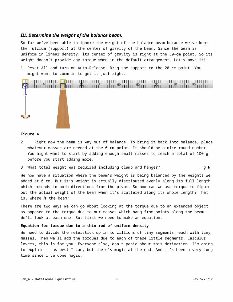
III. Determine the weight of the balance beam.So far we’ve been able to ignore the weight of the balance beam because we’ve kept the fulcrum (support) at the center of gravity of the beam. Since the beam is uniform in linear density, its center of gravity is right at the 50-cm point. So its weight doesn’t provide any torque when in the default arrangement. Let’s move it!
1. Reset All and turn on Auto-Release. Drag the support to the 20 cm point. You might want to zoom in to get it just right.
Figure 4
2. Right now the beam is way out of balance. To bring it back into balance, place whatever masses are needed at the 0 cm point. It should be a nice round number. You might want to start by adding enough small masses to reach a total of 100 g before you start adding more.
3. What total weight was required including clamp and hanger? . g N
We now have a situation where the beam’s weight is being balanced by the weights we added at 0 cm. But it’s weight is actually distributed evenly along its full length which extends in both directions from the pivot. So how can we use torque to figure out the actual weight of the beam when it’s scattered along its whole length? That is, where is the beam?
There are two ways we can go about looking at the torque due to an extended object as opposed to the torque due to our masses which hang from points along the beam.. We’ll look at each one. But first we need to make an equation.
Equation for torque due to a thin rod of uniform densityWe need to divide the meterstick up in to zillions of tiny segments, each with tiny masses. Then we’ll add the torques due to each of these little segments. Calculus lovers, this is for you. Everyone else, don’t panic about this derivation. I’m going to explain it as best I can, but there’s magic at the end. And it’s been a very long time since I’ve done magic.
Lab_a – Rotational Equilibrium 5 Rev 5/23/12

In Figure 5 you see our rod divided into lots of tiny segments which we can make as small as we like. Each segment is identical in length and hence mass and weight. The axis of rotation is at the left end.
The torque due to each segment equals its weight, wi, times its lever arm, ri. We’ll describe the weight in terms of the length using the linear density, μ, which is the mass/length in kg/m. E.g. A 2-cm section will have a mass of (.02 m)(μ kg/m)
Figure 5 – Torque of a thin rod
The net torque is the sum of these torques:
τ=r1 w1+r2 w2+…+rN wN=r1m1 g+r2m2 g+…+r N mN gor
τ=∑i=1
N
ri wi=∑i=1
N
r i mi g=∑i=1
N
r i μ Δ r g=μ g∑i=1
N
ri Δ r
Note that μ Δr is mass/length × the length of one tiny mass segment which gives the mass of that segment. So we have the lever arm × the mass × g which is the torque for a small section. We need to convert this infinite sum to an integral to produce an equation. That looks like the following.
τ=μg∫o
L
r Δr=μg r2
2│r=0
r=L
τ=μg L2
2=μLg L
2=W L
2
τ=W L2
Whew!
So for a regular beam of uniform linear density like ours, the torque equals the entire weight times half the length of the beam! So it acts as if all its weight is at its center which is why we call it the center of mass or center of gravity. And, with a bit more work we can show that the location of the axis is immaterial. That is, we could have put the axis anywhere and we’d get the same result.
Important Punch line If you know the location of the center of gravity of an extended body you can treat it as if all its weight acts at that point.
Now we have our equation so you can find the weight or mass of the beam. The torque equation is just
Torqueccw due to the hanging mass at 0 cm = Torquecw due to the beam’s weight at 50 cm.
4. Weight of beam = g N
Show your calculations of the weight of the beam
Lab_a – Rotational Equilibrium 6 Rev 5/23/12
There’s another way to look at this and it’s worth doing because this center of gravity calculation causes a lot of confusion. Here’s the point of confusion: “Why can we just ignore the left end of the beam?”
OK, let’s not “ignore” it and see how that goes. On the figure below, the weight of the beam you used in the previous calculation is shown. That’s the one we’re going to ignore. This time we’ll look at the beam as two independent segments either side of the fulcrum, each with its own weight and center of gravity.
Figure 6
5. We need the linear density, μ. The linear density is the mass/length for the beam. You know both its mass and length now. Show the calculations in this space → μ = mass (kg) / length (m) =
μ = kg/m
6. The left end of the beam is .200 m long. Using mass = μ × length, determine the mass of the 20 cm left end.
mleft end = kg
7. The center of gravity of the left end is at the center of this 20-cm section.
lever arm of left end = m
8. Similarly,
mright end = kg
lever arm of right end = m
9. On Figure 6, draw scaled weight vectors for each of these weights similar to the Wbeam vector already shown. They should be at the locations you supplied above.
10. Calculate the ccw torque and cw torque with this new configuration of the beam. Don’t forget the mass hanger.
Show your calculations of the clockwise and counter-clockwise torques.
τccw =
=
=
τcw =
=
=
Hopefully you noticed that this calculation can be done either way. It’s simpler to do as one piece.
Lab_a – Rotational Equilibrium 7 Rev 5/23/12

IV. Torque due to forces not perpendicular to the lever
The torque produced is maximum when a force acts perpendicular to the “lever.” But in many cases, that’s not the most convenient direction for the force to act. The guy wires supporting a vertical pole would be most effective if they could act horizontally (wire 1), but they generally have to be attached to the ground (wire 2), thus they’re under an extra amount of tension which requires thicker wires, strong anchors, etc.
Figure 7
There are two ways at working with torque in this sort of arrangement. We’ll look at both and then go back to the lab and try them both.
The torque equation is actually an example of a cross product. A cross product is found to describe situations where the product of two vectors is
a. a vector perpendicular to the plane formed by the two vectors.In our case the new vector is the torque and its direction is out of the page when the force tends to cause a counterclockwise rotation and into the page when the force tends to cause a clockwise rotation.
b. equal to the product of the magnitudes of the two vectors times the sign of the angle between the vectors.In our case that product is given by
τ⃑=r⃑ × F⃑=r F sin(θ) where θ is the angle between r and F.
We can use this equation to consider in either of two ways, whichever is more convenient.
Case I. τ = r F sin(θ)
The force, F can be represented in terms of its two components, F sin(θ) and F cos(θ). The total torque would be the sum of the torques of these two components.
F cos(θ) is the component collinear with r and as a result passes through the axis and has no lever arm. Thus it produces no torque.
F sin(θ) is the component perpendicular to r and thus provides a torque of r (F sin(θ))
Figure 7a
Case II. τ = r sin(θ) F
The lever arm, r⊥ equals r sin(θ).
Thus the torque, τ = r⊥ F=r sin (θ ) F
F sin(θ) is the component perpendicular to r and thus provides a torque of r (F sin(θ))
The choice of which way to use the equation is entirely determined by convenience. Sometimes it’s easier to think about a problem in one way and sometimes the other.
Figure 7bLet’s try it with our apparatus. This time we’ll use the balloons. You’ll see why we need the balloons shortly.
Lab_a – Rotational Equilibrium 8 Rev 5/23/12

Figure 8
Figure 8 shows the initial configuration of the apparatus for this section. Here’s how to set it up.
1. Reset All. Turn on Auto-Release.
2. Turn on Massless Clamps. This means that the clamp’s mass is now 0 grams rather than 20 grams. This makes the calculations more intuitive once you start to use the pulley to adjust the direction of the upward force.
3. Add a clamp and mass hanger at the 30-cm point. Add 150 g for a total of 200 grams. Note: not 220 grams.
Add a clamp at the 10-cm point. We need a clockwise torque to balance the 200-g mass. Thus we need an upward force. That’s what the helium balloons are for. On the right side of the screen you’ll see four pulleys with strings attached to red, green, blue, and purple, rod and loop assemblies. At the top end of each string is a balloon which goes off screen.
4. Drag the red rod and release it when its loop is below the center pin of the clamp you just attached at 10 cm. Nothing will happen because the balloon doesn’t supply enough buoyant force to counter the torque of the 100-g mass. The buoyant force of the balloons is measured in grams to match the units used by the hanging masses. So a “50-gram” balloon exerts an upward buoyant force equal to the downward force due to the weight of a 50-gram mass.
Lab_a – Rotational Equilibrium 9 Rev 5/23/12

5. There is a numeric stepper for each balloon that’s color coded to match the balloon. Find the red one and begin increasing its value until the beam comes into balance. (You’ll notice the balloon increasing in volume.)
You should find that 100 grams is required for balance. Here’s the math.
τ clockwise=−τ counterclockwise
or more simply ¿ τ clockwise∨¿∨τcounterclockwise∨¿
omitting the | |’s and - sign, (r balloon⊥ ) ( Fballoon )=(rhanger⊥)(Fhanger)
(.400 cm) (.100 g N) = (.200 cm) (.200 g N)
So why the balloons? Just to get an upward force? Nope. We need to look at forces not perpendicular to the beam. The pulleys attached to the side of the string give us that capability.
6. Grab the pulley by its gold handle and pull it to the right and release it. Down goes the left end of the beam which means that there’s insufficient clockwise torque.
There are two ways of explaining the reduction in torque. You’ll recognize them from the introduction to this section.
The y-component of the force is reduced. (Note that the string tension is not changed. The pulley just redirects it.) The lever arm, rballoon⊥, is reduced.
Let’s try both ways of looking at this.
7. To measure our angles we’ll need a protractor. Click the check box under the red mass stepper.There’s one small problem. Pull the string over to 60°. Is θ = 60°? No.θ is the angle between r and F where r is a line from the center of the support pivot out to where the string attaches to the clamp. So θ is the compliment of 60°. We’ll call 60° angle read from the protractor ϕ. You’ll record both angles in the table.
8. Adjust the pulley to ϕ = 0°. This is the first entry in the table. You’ve already done this case so you should be able to fill in all but the last two columns in the first row.
9. The last two columns are also simple for this first case. In this case r⊥=r so you know r⊥. And you know Fb.You should find that your torque values in columns 6 and 8 are equal.What about the other r⊥values? You’ll measure them. Click on the Lever Arm Tool check box and drag the ruler out to make your measurement! (See Figure 9 on the next page.)
10. Repeat making the measurements and calculations for the other three angles in the table.
Table 2 Torque = r F sin(θ) = r sin(θ) FTorque due to mass hanger at 30 cm ________ g m N
ϕ(°)
θ(°)
Fbuoyant
(g N)F⊥
(g N)
r(m)
(r ) ( F⊥ )(g m N)
r⊥(m)
r⊥ Fb
(g m N)
0 90
30 60 .116
45 45 .142
60 30 .200
Lab_a – Rotational Equilibrium 10 Rev 5/23/12

Figure 9 – Use of the Lever Arm Tool
Lab_a – Rotational Equilibrium 11 Rev 5/23/12

Blank Page
Lab_a – Rotational Equilibrium 12 Rev 5/23/12


![[ENTITY NAME] - Ohio Auditor of State · Web viewNAME] [COUNTY NAME] COUNTY. XYZ. ... you should identify the specific types of ... District for any purpose provided it is expended](https://img.pdfslide.us/doc/110x75/5af7e1ff7f8b9a8d1c90d803/entity-name-ohio-auditor-of-state-viewname-county-name-county-xyz-you.jpg)