Embed Size (px)
Citation preview

Prostage S.L. • Apdo 57 • ES-07560 Cala [email protected] • www.prostage.eu
PurpleLine Users Manual
Firmware version 1.60As at 31 October 2012
Page 1
Table of Contents
1. Introduction
2. Terminology
3. Connecting your System
3.1 The XTMpro 3.1.1 Power Supply3.1.2 StageWire3.1.3 USB3.1.4 MIDI3.1.5 Tap Relay3.1.6 The Switching Relays Option (XTMpro-R only)
3.2 Setting up the XDS Drawer3.2.1 Fitting the XDS System in your Rack3.2.2 Fitting the Stompboxes (Pedal Effects) in the XDS3.2.3 Connecting External Units to the XDS3.2.4 The Power Supplies of the XDS3.2.5 Two-Button Stompbox
3.3 The Audio Connections of XLS and XDS Loop Systems
3.3.1 Connecting the Loops3.3.2 Tuner / Mute Function3.3.3 Stereo
3.4 Foot Controller3.4.1 Connecting an Expression Pedal to the Foot
Controller3.4.2 Calibration of the Expression Pedal
4. Hum
5.0 Using Your System
5.1 The Foot Controllers
5.2 The XTMpro (with Relay Option)
5.3 The XDS and XLS Loop System
6. The Prostage System Manager Software
6.1 Installing the System Manager Software (Mac & PC)
6.1.1 Installing the USB Driver on Mac OSX6.1.2 Installing the USB driver on Windows6.1.3 Running the System Manager6.1.4 The File Menu6.1.5 The Edit Menu
6.2 The “XTMpro Basic Settings” Tab6.2.1 General Settings / Foot Controller6.2.2 MIDI In6.2.3 MIDI Thru Filter6.2.4 Tap Function6.2.5 Relay Option
6.3 The “Program Mapping” Tab6.3.1 Basic Settings of the “Program Mapping”
Table6.3.2 Defining Mappings6.3.3 Mapping Mode “Program Number”6.3.4 Mapping Mode “Control Change”6.3.5 Mapping Mode “Convert incoming CC”6.3.6 Mapping Mode “Send Tap Tempo”
6.4 The “Relays” Tab
6.5 The “Switch Assignment” Tab
6.6 The “Foot Controller Settings” Tab6.6.1 Foot Controller List6.6.2 Operating Modes6.6.3 Tap Switch6.6.4 Sidekick (X05 and X10)6.6.5 Foot Controller Basic Settings6.6.6 Display Settings (X05 and X10)6.6.7 Using Default Settings6.6.8 Rename Foot Controller
6.7 The “Remote WahWah” Tab
7. Firmware Upgrade
7.1 How to Upgrade the Firmware of the XTMpro
7.2 How to Upgrade the Firmware of a Foot Controller
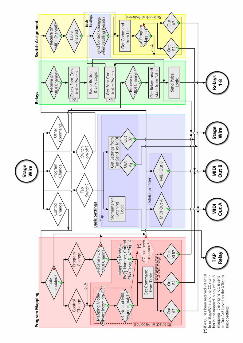
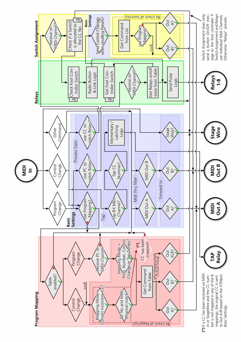
8. Appendix: Signal Flow Charts of the XTMpro
9. Warning Instructions and Warranty
Page 2
1. Introduction
Dear Customer
Thank you for buying the Prostage System. You have chosed the most advanced loop and switch system available in the world. As Prostage PurpleLine is a coherent system, this manual covers all PurpleLine units. There are no separate manuals for a single foot controller or a loop system.If you have any questions, or if something does not work as you expect, please do not hesitate to contact us: [email protected]. Your questions will also help us to improve this users manual.We are also looking forward to your suggestions concerning new features. We are still working to improve the functionality of the system. You can easily upgrade the units’ software yourself. For more information about this topic, see chapter 7 “Firmware Upgrade”.
The philosophy on the Prostage PurpleLine system is “control without limits”. We want you to be able to setup your system exactly as you want it to work while keeping it as simple to use as possible. Therefore, there are lots of things inside the system you can configure. You will note that the chapters “Connecting your System” and “The Prostage System Manager Software” cover most pages of this manual, while the chapter “Using Your System” is less than one page. This means, once you have configured the system properly, you will be able control your entire equipment with a single footstep, except of the coffee machine ;-)
2. Terminology
PurpleLine:PurpleLine are all Prostage units which are equipped with the innovative StageWire technology (see the sections below). The units’ color is purple. The XLR connectors are labeled “StageWire”.
BlackLine:This are the “old” Prostage products which send a standard MIDI signal via XLR. The units are colored black. The XLR connectors are labeled “IN” / “OUT”. BlackLine and PurpleLine foot controllers are not compatible with each other.
StageWire:StageWire is a technology developed by Prostage especially to be used on stage. StageWire is a connection that enables several devices to communicate with each other via a standard microphone cable. It is four times faster than MIDI. Using only one microphone cable from one device to another device, they can communicate with each other in both directions (bi-directional). Furthermore, the microphone cable supplies the foot controllers with power.
MIDI:See www.midi.org (http://www.midi.org/aboutmidi/intromidi.pdf)
Program Change | PC:Program Change messages are used to recall presets or switch sounds on connected devices. We use the short form “PC” in the System Manager software for MIDI “Program Change” message. A Program Change consists of a MIDI channel (1-16), and the program number 0-127 (most units display them as 1-128).
Control Change | CC:Control Change messages let you call and automate parameters and functions in real time. A Control Change message can, for example, vary the volume. The short form “CC” stands for MIDI “Control Change”; it is often also called “Continuous Controller”. A CC message consists of a MIDI channel (1-16), a controller number and a value 0-127.
On/Off Switches:Besides the standard MIDI commands, StageWire also allows you to send instant access messages. They are used for example to switch the Relays of the XTMpro. On/Off Switches work in a similar way like an analog foot switch connected directly to your amplifier, e.g to switch channels. An On/Off Switch message consists of a MIDI channel (1-16), a switch number (1-8) and the On/Off state.
Relay:A remotely controlled switch.
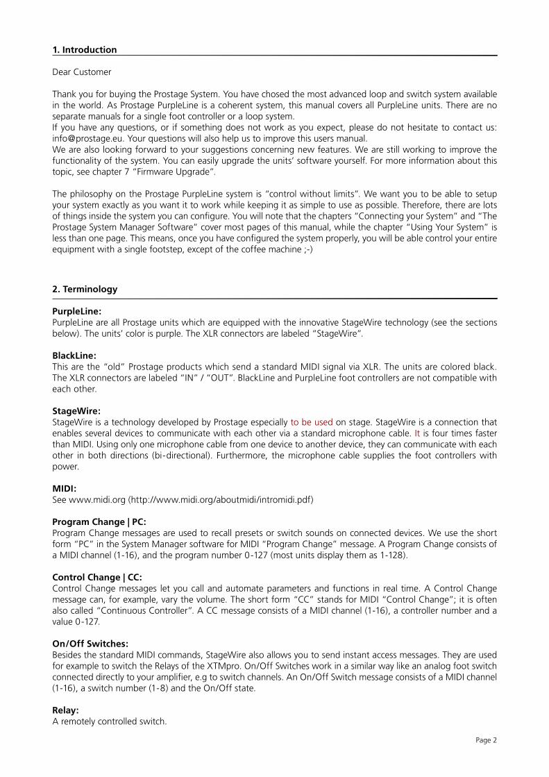
AmpGuitar
Tap Relay of XTMpro
Page 3
3. Connecting your System
The Prostage System always consists of one master unit (XTMpro, XDS. XLS) and up to 14 foot controllers. In other words, you can connect up to 15 PurpleLine units in a row. The master unit supplies the entire system with power.The XTMpro is the “heart” of the system. XDS and XLS use the same electronics like XTMpro. This means, the chapter “XTMpro” also applies to XDS and XLS.IMPORTANT => You can connect a BlackLine foot controller to a PurpleLine master unit (XDS, XLS,XTMpro), but you cannot connect a PurpleLine foot controller to the black XTM adaptor. Do NOT mix PurpleLine and BlackLine foot controllers! All foot controllers must be the same color.
3.1 The XTMpro
=> The instructions concerning “XTMpro” also apply to XDS and XLS Loop Systems!
3.1.1 Power Supply
The XTMpro is powered by a 9V or 12V, AC or DC power supply.XDS and XLS loop systems are powered with 220-240VAC or 110-120VAC (see marking beside power cable).The red LED of the XTMpro indicates that the system is on:Blinking LED => the XTMpro is working, but no foot controller has been detected.Solid LED => The System is working and the communication with the foot controller works properly.LED flickers => The XTMpro receives data on StageWire input.
3.1.2 StageWire | Foot Controller
Use a standard microphone cable to connect the StageWire connector of your XTMpro with the “Main” connector of your foot controller. If you have more than one foot controller, use the “Link” connector of your first foot controller to connect it with the “Main” of your next foot controller. And so on .....The cable must not be longer than 200 meters. You can also send via a single-shielded audio-multicore.IMPORTANT => StageWire does not work with phase reversed cables (microphones still work like this). Make sure that the cables are soldered properly.
3.1.3 USB
The XTMpro needs the USB connection to communicate with the System Manager software (see chapter 6).
3.1.4 MIDI
There are one MIDI In and two MIDI Outs to connect all your MIDI gear. If you are not familiar with MIDI, please see the user’s manual of your MIDI unit (Multi Effect, Amplifier, ...) or get the basic knowledge from www.midi.org (http://www.midi.org/aboutmidi/intromidi.pdf).There are lots of possibilities to map, distribute and modify the MIDI data inside the XTMpro. This will be configured using the System Manager software. (see chapter 6).
3.1.5 Tap Relay
The Tap relay connector is an isolated switch contact. You can use it to tap tempo based parameters of your effect unit such as delay time, provided that this unit has a connector for a Tap foot-switch. You simply connect the Tap relay connector of your XTMpro using a Jack-Jack cable to the Tap switch connector of your effects unit. The Tap relay is a toggle switch:
Tip => normally openRing => normally closedShield => Common
NOTE => The Tap relay can also be used as a Mute function if you wire a special cable:
3.1.6 The Switching Relays Option (XTMpro-R only)
The four relays can be used, for example, to switch amp channels or boost functions.You simply have to connect the sockets 1 to 4 with the foot-switch sockets (Jack) of your amplifier, or whatever you like to control, using Jack-Jack cables. If your controlled unit has a stereo Jack, or a multi-pin socket, we can provide a custom cable. The relays’ are hard-wired like the Tap relay (see scheme above).
PSU
3.2 Setting up the XDS Drawer
3.2.1 Fitting the XDS System in your Rack
The XDS is made of aluminum to save weight. To keep stability, please consider the following when installing it into a 19” Rack:- Install the drawer at the very bottom of the rack and make sure that the rear part of the drawer is supported. If you want to install the drawer somewhere else than at the very bottom of your rack, we highly recommend you to prop up the rear part of the drawer. Keep in mind that your stompboxes may be more comfortable to handle if the drawer is at the very bottom of the rack. Further, you can leave the drawer open during the show without blocking the access to the other units in your rack. - The XDS ships with four big washers. Use them under the M6 screws with which the drawer is installed into the Rack. The washers protect the ears/lugs and will make the construction sturdier.- Make sure the drawer is completely closed before you tighten the screws. Tighten the two lower screws first. Before you tighten the upper screws, adjust the mounting ears so that they are parallel with the drawer. This way, you make sure that the drawer will close perfectly.
3.2.2 Fitting the Stompboxes (Pedal Effects) in the XDS
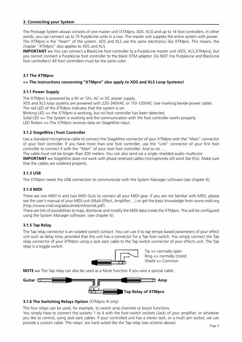
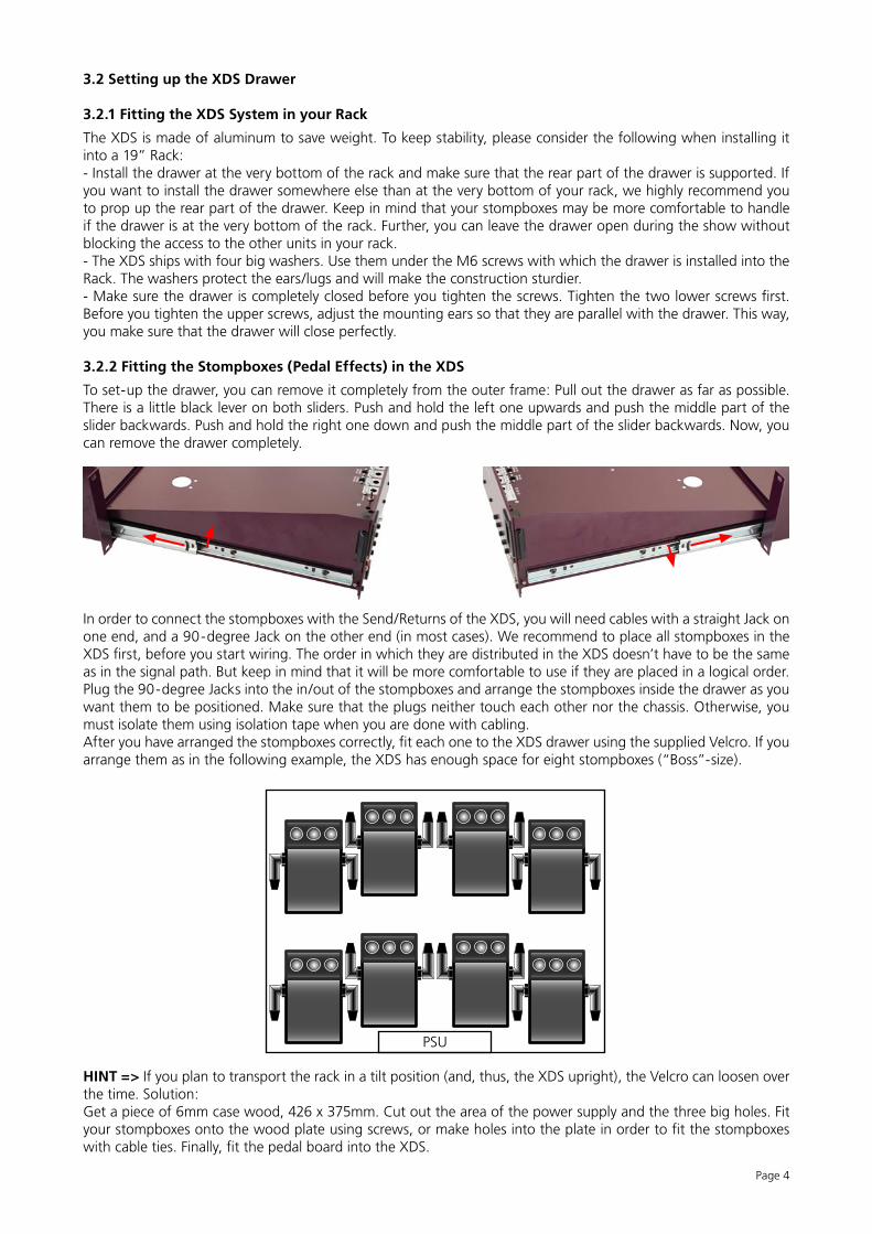
To set-up the drawer, you can remove it completely from the outer frame: Pull out the drawer as far as possible. There is a little black lever on both sliders. Push and hold the left one upwards and push the middle part of the slider backwards. Push and hold the right one down and push the middle part of the slider backwards. Now, you can remove the drawer completely.
In order to connect the stompboxes with the Send/Returns of the XDS, you will need cables with a straight Jack on one end, and a 90-degree Jack on the other end (in most cases). We recommend to place all stompboxes in the XDS first, before you start wiring. The order in which they are distributed in the XDS doesn’t have to be the same as in the signal path. But keep in mind that it will be more comfortable to use if they are placed in a logical order.Plug the 90-degree Jacks into the in/out of the stompboxes and arrange the stompboxes inside the drawer as you want them to be positioned. Make sure that the plugs neither touch each other nor the chassis. Otherwise, you must isolate them using isolation tape when you are done with cabling. After you have arranged the stompboxes correctly, fit each one to the XDS drawer using the supplied Velcro. If you arrange them as in the following example, the XDS has enough space for eight stompboxes (“Boss”-size).
HINT => If you plan to transport the rack in a tilt position (and, thus, the XDS upright), the Velcro can loosen over the time. Solution:Get a piece of 6mm case wood, 426 x 375mm. Cut out the area of the power supply and the three big holes. Fit your stompboxes onto the wood plate using screws, or make holes into the plate in order to fit the stompboxes with cable ties. Finally, fit the pedal board into the XDS.
Page 4
Page 5
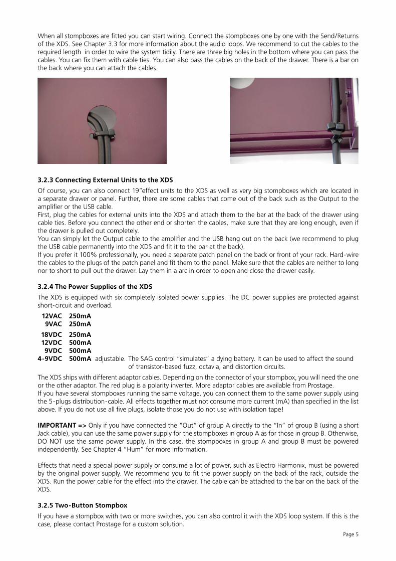
When all stompboxes are fitted you can start wiring. Connect the stompboxes one by one with the Send/Returns of the XDS. See Chapter 3.3 for more information about the audio loops. We recommend to cut the cables to the required length in order to wire the system tidily. There are three big holes in the bottom where you can pass the cables. You can fix them with cable ties. You can also pass the cables on the back of the drawer. There is a bar on the back where you can attach the cables.
3.2.3 Connecting External Units to the XDS
Of course, you can also connect 19”effect units to the XDS as well as very big stompboxes which are located in a separate drawer or panel. Further, there are some cables that come out of the back such as the Output to the amplifier or the USB cable.First, plug the cables for external units into the XDS and attach them to the bar at the back of the drawer using cable ties. Before you connect the other end or shorten the cables, make sure that they are long enough, even if the drawer is pulled out completely.You can simply let the Output cable to the amplifier and the USB hang out on the back (we recommend to plug the USB cable permanently into the XDS and fit it to the bar at the back). If you prefer it 100% professionally, you need a separate patch panel on the back or front of your rack. Hard-wire the cables to the plugs of the patch panel and fit them to the panel. Make sure that the cables are neither to long nor to short to pull out the drawer. Lay them in a arc in order to open and close the drawer easily.
3.2.4 The Power Supplies of the XDS
The XDS is equipped with six completely isolated power supplies. The DC power supplies are protected against short-circuit and overload.
12VAC 250mA 9VAC 250mA
18VDC 250mA 12VDC 500mA 9VDC 500mA 4-9VDC 500mA adjustable. The SAG control “simulates” a dying battery. It can be used to affect the sound of transistor-based fuzz, octavia, and distortion circuits.
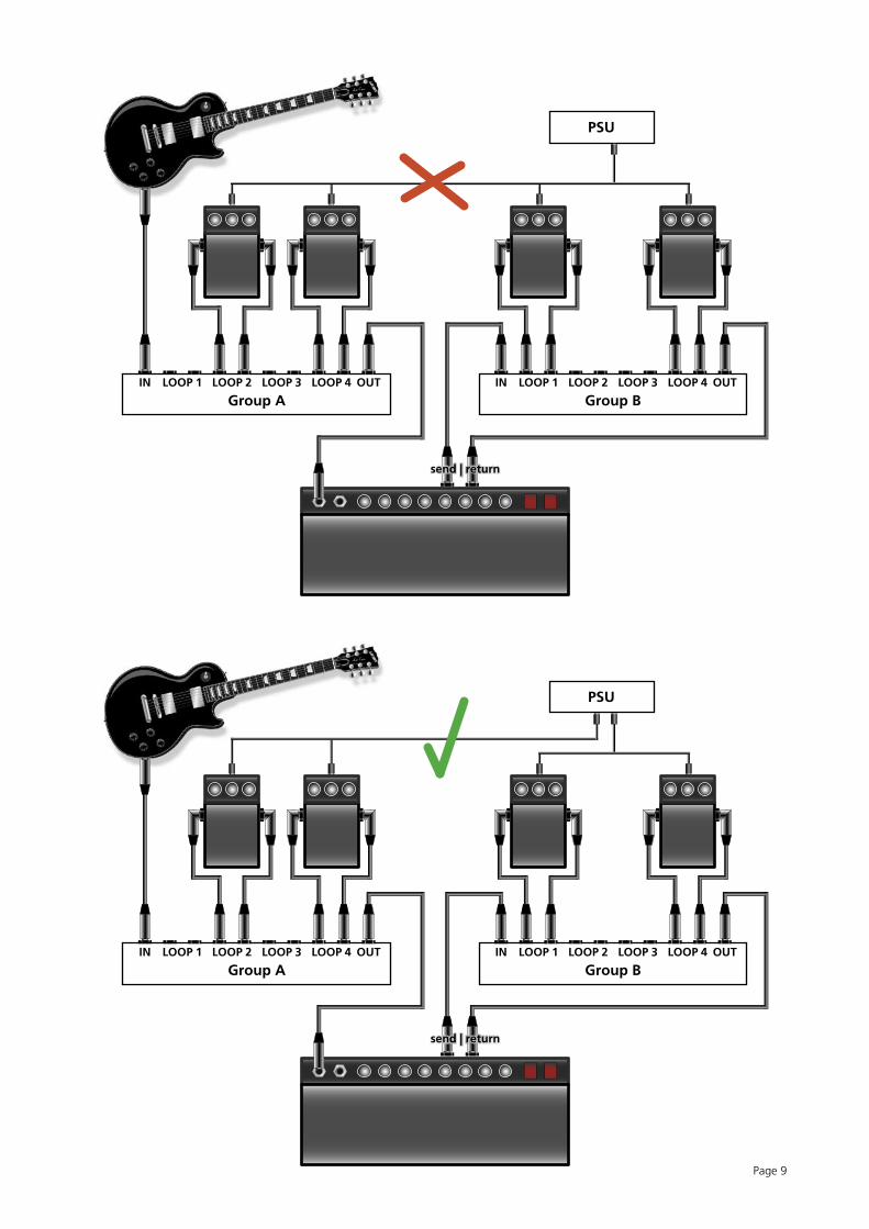
The XDS ships with different adaptor cables. Depending on the connector of your stompbox, you will need the one or the other adaptor. The red plug is a polarity inverter. More adaptor cables are available from Prostage.If you have several stompboxes running the same voltage, you can connect them to the same power supply using the 5-plugs distribution-cable. All effects together must not consume more current (mA) than specified in the list above. If you do not use all five plugs, isolate those you do not use with isolation tape!
IMPORTANT => Only if you have connected the “Out” of group A directly to the “In” of group B (using a short Jack cable), you can use the same power supply for the stompboxes in group A as for those in group B. Otherwise, DO NOT use the same power supply. In this case, the stompboxes in group A and group B must be powered independently. See Chapter 4 “Hum” for more Information.
Effects that need a special power supply or consume a lot of power, such as Electro Harmonix, must be powered by the original power supply. We recommend you to fit the power supply on the back of the rack, outside the XDS. Run the power cable for the effect into the drawer. The cable can be attached to the bar on the back of the XDS.
3.2.5 Two-Button Stompbox
If you have a stompbox with two or more switches, you can also control it with the XDS loop system. If this is the case, please contact Prostage for a custom solution.
Page 6
3.3 The Audio Connections of XLS and XDS Loop Systems
NOTE => If one group of your XDS/XLS is equipped with only four plugs instead of ten, then this group is equipped with switching relays instead of loops. See chapter 3.1.6 in this case.
IMPORTANT => Please read also chapter 4 “Hum” before you start to connect all your gear.
3.3.1 Connecting the Loops
There are many ways to use the loops of your XDS/XLS: For example, you can use group A before the amplifier and group B in the Send/Return of your amplifier. Group A and B are completely independent. This means that there is no ground connection between group A and group B.Basically, your guitar is connected to the “In”, and the “Out” is connected to the amplifier. The “Send” of the XDS is connected to your effect Input, the related “Return” is connected to your effect Out.If you like to use all eight loops in series, connect “Out A” with “In B” using a short Jack-Jack cable.
3.3.2 Tuner / Mute Function
You can use one loop as a Mute / Tuner function:- Connect the Input of your tuner to the “Send” (the Output of the tuner will not be connected).- Plug a short-circuited Jack-plug into the “Return” (Tip connected with shield).
Mute plug
3.3.3 Stereo
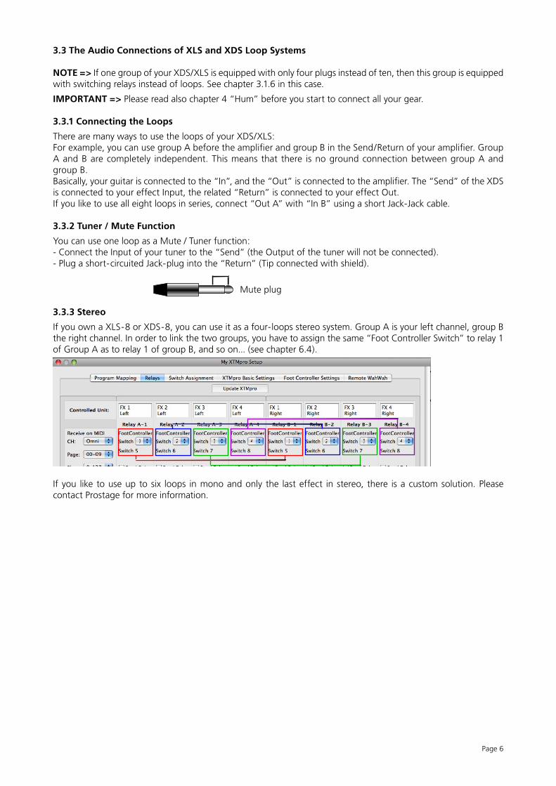
If you own a XLS-8 or XDS-8, you can use it as a four-loops stereo system. Group A is your left channel, group B the right channel. In order to link the two groups, you have to assign the same “Foot Controller Switch” to relay 1 of Group A as to relay 1 of group B, and so on... (see chapter 6.4).
If you like to use up to six loops in mono and only the last effect in stereo, there is a custom solution. Please contact Prostage for more information.
3.4 Foot Controller
The foot controller(s) do not need a power adaptor. They are powered via the StageWire connection.
3.4.1 Connecting an Expression Pedal to the Foot Controller
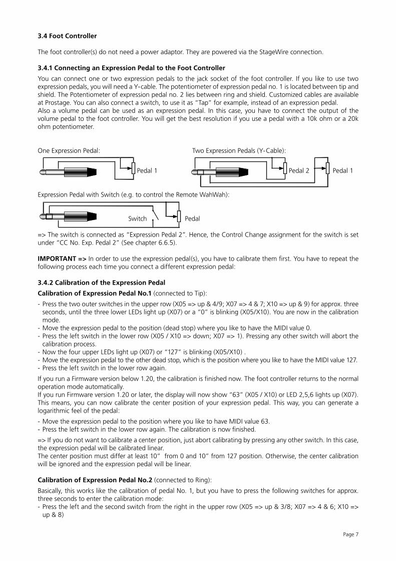
You can connect one or two expression pedals to the jack socket of the foot controller. If you like to use two expression pedals, you will need a Y-cable. The potentiometer of expression pedal no. 1 is located between tip and shield. The Potentiometer of expression pedal no. 2 lies between ring and shield. Customized cables are available at Prostage. You can also connect a switch, to use it as “Tap” for example, instead of an expression pedal.Also a volume pedal can be used as an expression pedal. In this case, you have to connect the output of the volume pedal to the foot controller. You will get the best resolution if you use a pedal with a 10k ohm or a 20k ohm potentiometer.
One Expression Pedal: Two Expression Pedals (Y-Cable):
Pedal 1 Pedal 2 Pedal 1
Expression Pedal with Switch (e.g. to control the Remote WahWah):
Switch Pedal
=> The switch is connected as “Expression Pedal 2”. Hence, the Control Change assignment for the switch is set under “CC No. Exp. Pedal 2” (See chapter 6.6.5).
IMPORTANT => In order to use the expression pedal(s), you have to calibrate them first. You have to repeat the following process each time you connect a different expression pedal:
3.4.2 Calibration of the Expression Pedal
Calibration of Expression Pedal No.1 (connected to Tip):
- Press the two outer switches in the upper row (X05 => up & 4/9; X07 => 4 & 7; X10 => up & 9) for approx. three seconds, until the three lower LEDs light up (X07) or a “0” is blinking (X05/X10). You are now in the calibration mode.
- Move the expression pedal to the position (dead stop) where you like to have the MIDI value 0.- Press the left switch in the lower row (X05 / X10 => down; X07 => 1). Pressing any other switch will abort the
calibration process.- Now the four upper LEDs light up (X07) or “127” is blinking (X05/X10) .- Move the expression pedal to the other dead stop, which is the position where you like to have the MIDI value 127.- Press the left switch in the lower row again.
If you run a Firmware version below 1.20, the calibration is finished now. The foot controller returns to the normal operation mode automatically.If you run Firmware version 1.20 or later, the display will now show “63” (X05 / X10) or LED 2,5,6 lights up (X07). This means, you can now calibrate the center position of your expression pedal. This way, you can generate a logarithmic feel of the pedal:
- Move the expression pedal to the position where you like to have MIDI value 63.- Press the left switch in the lower row again. The calibration is now finished.
=> If you do not want to calibrate a center position, just abort calibrating by pressing any other switch. In this case, the expression pedal will be calibrated linear.The center position must differ at least 10” from 0 and 10” from 127 position. Otherwise, the center calibration will be ignored and the expression pedal will be linear.
Calibration of Expression Pedal No.2 (connected to Ring):
Basically, this works like the calibration of pedal No. 1, but you have to press the following switches for approx. three seconds to enter the calibration mode:- Press the left and the second switch from the right in the upper row (X05 => up & 3/8; X07 => 4 & 6; X10 =>
up & 8)
Page 7
IN OUTLOOP 1 LOOP 2 LOOP 3 LOOP 4
Group AIN OUTLOOP 1 LOOP 2 LOOP 3 LOOP 4
Group B
PSU
Page 8
4. Hum
Hum is a very broad issue. We will add more information on it as soon as possible. If you are having hum problems, please contact us. We will be glad to help you.
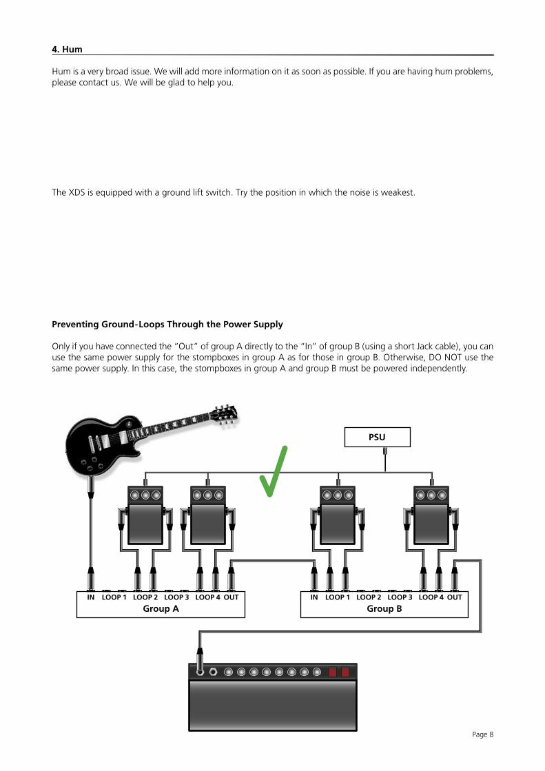
The XDS is equipped with a ground lift switch. Try the position in which the noise is weakest.
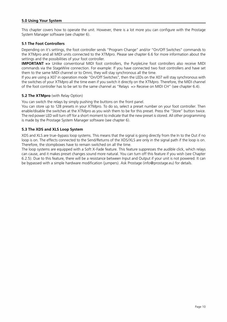
Preventing Ground-Loops Through the Power Supply
Only if you have connected the “Out” of group A directly to the “In” of group B (using a short Jack cable), you can use the same power supply for the stompboxes in group A as for those in group B. Otherwise, DO NOT use the same power supply. In this case, the stompboxes in group A and group B must be powered independently.
IN OUTLOOP 1 LOOP 2 LOOP 3 LOOP 4
Group AIN OUTLOOP 1 LOOP 2 LOOP 3 LOOP 4
Group B
PSU
send | return
IN OUTLOOP 1 LOOP 2 LOOP 3 LOOP 4
Group AIN OUTLOOP 1 LOOP 2 LOOP 3 LOOP 4
Group B
PSU
send | return
Page 9
Page 10
5.0 Using Your System
This chapter covers how to operate the unit. However, there is a lot more you can configure with the Prostage System Manager software (see chapter 6).
5.1 The Foot Controllers
Depending on it’s settings, the foot controller sends “Program Change” and/or “On/Off Switches” commands to the XTMpro and all MIDI units connected to the XTMpro. Please see chapter 6.6 for more information about the settings and the possibilities of your foot controller.IMPORTANT => Unlike conventional MIDI foot controllers, the PurpleLine foot controllers also receive MIDI commands via the StageWire connection. For example: If you have connected two foot controllers and have set them to the same MIDI channel or to Omni, they will stay synchronous all the time. If you are using a X07 in operation mode “On/Off Switches”, then the LEDs on the X07 will stay synchronous with the switches of your XTMpro all the time even if you switch it directly on the XTMpro. Therefore, the MIDI channel of the foot controller has to be set to the same channel as “Relays => Receive on MIDI CH” (see chapter 6.4).
5.2 The XTMpro (with Relay Option)
You can switch the relays by simply pushing the buttons on the front panel.You can store up to 128 presets in your XTMpro. To do so, select a preset number on your foot controller. Then enable/disable the switches at the XTMpro as you wish them to be for this preset. Press the “Store” button twice. The red power LED will turn off for a short moment to indicate that the new preset is stored. All other programming is made by the Prostage System Manager software (see chapter 6).
5.3 The XDS and XLS Loop System
XDS and XLS are true-bypass loop systems. This means that the signal is going directly from the In to the Out if no loop is on. The effects connected to the Send/Returns of the XDS/XLS are only in the signal path if the loop is on. Therefore, the stompboxes have to remain switched on all the time. The loop systems are equipped with a Soft X-Fade feature. This feature suppresses the audible click, which relays can cause, and it makes preset changes sound more natural. You can turn off this feature if you wish (see Chapter 6.2.5). Due to this feature, there will be a resistance between Input and Output if your unit is not powered. It can be bypassed with a simple hardware modification (jumpers). Ask Prostage ([email protected]) for details.
Page 11
6. The Prostage System Manager Software
On the XTMpro itself, you can only store presets for the relays. All other settings are made with the Prostage System Manager software (formerly known as “XTMpro Configuration Software”). It is available for Mac and PC. Please download the latest version as well as the USB driver from our website:www.prostage.eu => Downloads => Software & Driver
Make sure that the System Manager and the Firmware of the XTMpro / foot controller have the same version num-ber. Otherwise, there may be features in the System Manager which are not supported by the unit itself (or vice-versa). The last digit can be ignored: E.g. XTMpro Firmware Version 1.22 is compatible with the System Manager 1.20, but not with System Manager 1.30.
NOTE => Remember that the XDS and XLS use same brain as the XTMpro. Thus, if we are talking about XTMpro in the System Manager, this includes XDS or XLS.
6.1 Installing the System Manager Software (Mac & PC)
- Unzip the downloaded file.- Move the folder “Prostage System Manager xxx” into your local application folder. (DO NOT move any files inside
the folder to other locations).
6.1.1 Installing the USB Driver on Mac OSX
- Double click the downloaded file (.dmg) and follow the on-screen instructions.
6.1.2 Installing the USB driver on Windows
- Unzip the downloaded file.- When you connect the XTMpro for the first time, the assistant will ask you for a driver => Here, you have to select the path where you unzipped/stored the folder with the USB Driver before.
If the wizard does not open automatically, you need to install the driver via the “Device Manager”. Unfortunately, this is with every Windows version again elsewhere:Windows 2000: Start / Settings / Control Panel => System => Hardware / Device ManagerWindows 7: Windows icon left corner below / Control Pannel => System & Security => System => Device ManagerThe XTMpro must now appear under “Com & LPT” or “USB” or “Other Devices”. Double click “XTMpro”. This will open a new window. Find the button “Update Driver” and click it.Select “Manual Installation”. This opens the file dialog window. Select the file “XTMpro USB driver” (the previously unzipped driver, NOT the zip file!).Now the driver should be installed.
NOTE => The USB Driver may install and appear as “FTDI Driver”.
6.1.3 Running the System Manager
Make sure that the XTMpro is properly connected with your computer via USB.IMPORTANT => The System Manager is an offline tool. This means that you have to read out the XTMpro after launching the System Manager in order that it shows the current settings in your XTMpro. This happens automatically when you launch the software given that the XTMpro is properly connected with the computer. Otherwise, you have to read out the XTMpro manually: “File” => “Read XTMpro”.If you are working with two or more XTMpro’s, you have to read out the settings each time you plug the USB cable into a different device. Otherwise, you will mix the settings of the different devices.IMPORTANT => Changes made in the System Manager have to be confirmed with “Update XTMpro”. This will send all settings of the “Program Mapping”, “Relay”, “Switch Assignment” and “XTMpro Basic Settings” tab to the XTMpro. “Foot Controller Settings” and “Remote WahWah” are not stored in the XTMpro but in the foot controller or the Remote WahWah respectively. If you make any changes in one of the two tabs, you have to confirm them with the button “Update Foot Controller” or “Update Wah Wah” / “Store Preset” respectively.You can also save and open presets to / from your local hard disk (“File” Menu).NOTE => The preset-names, as well as the description of the eight Program Mapping banks and the eight Relays are only saved to your hard disk; they are not stored in the XTMpro. Thus, we recommend to save your settings to the hard disk as well.
Page 12
6.1.4 The File Menu
Open Configuration loads a previously saved setup into the System Manager (Filename extension: .pcf)
Save Configuration (as) saves the XTMpro configuration to your local hard disk. This includes all the settings from the “Program Mapping”, “Relays”, “Switch Assignment” and “XTMpro Basic Settings” tabs, as well as the “Foot Controller” default settings.
Read XTMpro loads the settings stored in the connected XTMpro into the System Manager.
Update XTMpro sends the current settings from the System Manager to the XTMpro.
Reset restores the factory defaults for different sections inside the System Manager.
Open WahWah Presets loads the presets for the Remote WahWah (see the Remote Wah’s users manual)
Save WahWah Presets (as) saves the presets for the Remote WahWah (see the Remote Wah’s users manual)
Page Setup allows you to adjust the paper size for printing the patch list
Print Patch List prints the entire “Program Mapping” table.
Quit closes the Software.
6.1.5 The Edit Menu
Toggle Preset opens a dialog box where you can interchange the current selected preset with another preset. All „Program Mapping“ and „Relais“ settings of the two presets will be exchanged.
MIDI In
Page 13
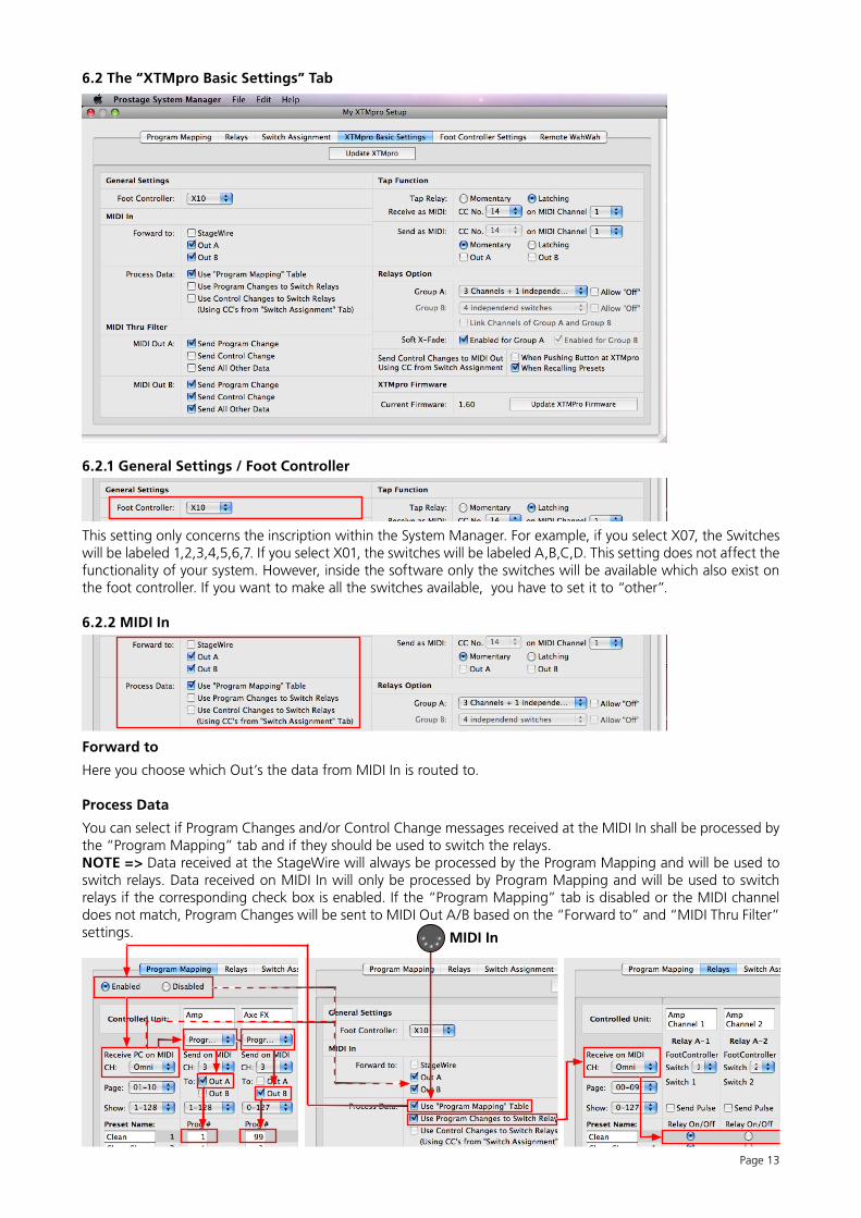
6.2 The “XTMpro Basic Settings” Tab
6.2.1 General Settings / Foot Controller
This setting only concerns the inscription within the System Manager. For example, if you select X07, the Switches will be labeled 1,2,3,4,5,6,7. If you select X01, the switches will be labeled A,B,C,D. This setting does not affect the functionality of your system. However, inside the software only the switches will be available which also exist on the foot controller. If you want to make all the switches available, you have to set it to “other”.
6.2.2 MIDI In
Forward to
Here you choose which Out’s the data from MIDI In is routed to.
Process Data
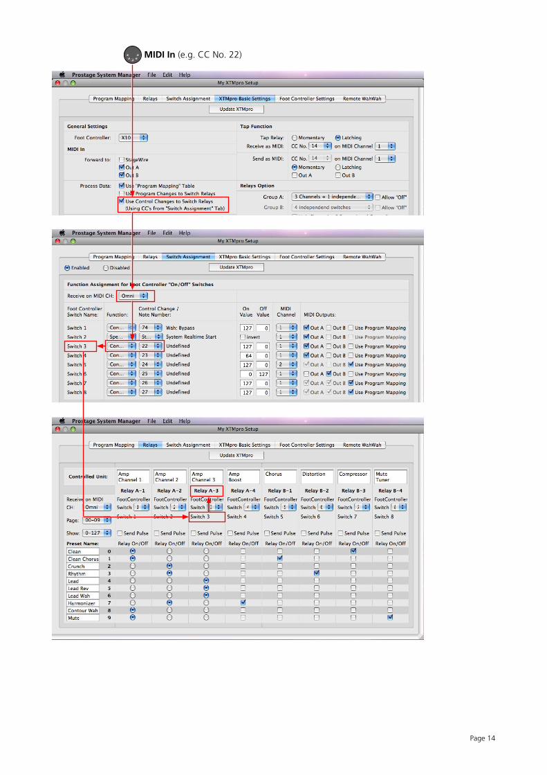
You can select if Program Changes and/or Control Change messages received at the MIDI In shall be processed by the “Program Mapping” tab and if they should be used to switch the relays.NOTE => Data received at the StageWire will always be processed by the Program Mapping and will be used to switch relays. Data received on MIDI In will only be processed by Program Mapping and will be used to switch relays if the corresponding check box is enabled. If the “Program Mapping” tab is disabled or the MIDI channel does not match, Program Changes will be sent to MIDI Out A/B based on the “Forward to” and “MIDI Thru Filter” settings.
Page 14
MIDI In (e.g. CC No. 22)
Page 15
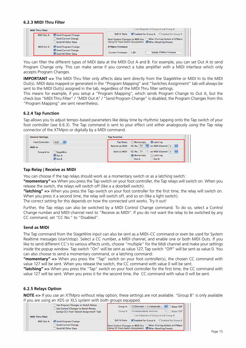
6.2.3 MIDI Thru Filter
You can filter the different types of MIDI data at the MIDI Out A and B. For example, you can set Out A to send Program Change only. This can make sense if you connect a tube amplifier with a MIDI interface which only accepts Program Changes.
IMPORTANT => The MIDI Thru filter only affects data sent directly from the StageWire or MIDI In to the MIDI Out(s). MIDI data mapped or generated in the “Program Mapping” and “Switches Assignment” tab will always be sent to the MIDI Out(s) assigned in the tab, regardless of the MIDI Thru filter settings. This means for example, if you setup a “Program Mapping”, which sends Program Change to Out A, but the check box “MIDI Thru Filter” / “MIDI Out A” / “Send Program Change” is disabled, the Program Changes from this “Program Mapping” are sent nevertheless.
6.2.4 Tap Function
Tap allows you to adjust tempo-based parameters like delay time by rhythmic tapping onto the Tap switch of your foot controller (see 6.6.3). The Tap command is sent to your effect unit either analogously using the Tap relay connector of the XTMpro or digitally by a MIDI command.
Tap Relay | Receive as MIDI
You can choose if the tap relays should work as a momentary switch or as a latching switch:“momentary” => When you press the Tap switch on your foot controller, the Tap relays will switch on. When you release the switch, the relays will switch off (like a a doorbell switch).“latching” => When you press the Tap-switch on your foot controller for the first time, the relay will switch on. When you press it a second time, the relay will switch off, and so on (like a light switch).The correct setting for this depends on how the connected unit works. Try it out!
Further, the Tap relays can also be switched by a MIDI Control Change command. To do so, select a Control Change number and MIDI channel next to “Receive as MIDI”. If you do not want the relay to be switched by any CC command, set “CC No.” to “Disabled”.
Send as MIDI
The Tap command from the StageWire input can also be sent as a MIDI-CC command or even be used for System Realtime messages (start/stop). Select a CC number, a MIDI channel, and enable one or both MIDI Outs. If you like to send different CC’s to various effects units, choose “multiple” for the Midi channel and make your settings inside the popup window. Tap switch “On” will be sent as value 127, Tap switch “Off” will be sent as value 0. You can also choose to send a momentary command, or a latching command:“momentary” => When you press the “Tap” switch on your foot controller(s), the chosen CC command with value 127 will be sent. When you release the switch, the CC command with value 0 will be sent.“latching” => When you press the “Tap” switch on your foot controller for the first time, the CC command with value 127 will be sent. When you press it for the second time, the CC command with value 0 will be sent.
6.2.5 Relays Option
NOTE => If you use an XTMpro without relay option, these settings are not available. “Group B” is only available if you are using an XDS or XLS system with both groups equipped.
Page 16
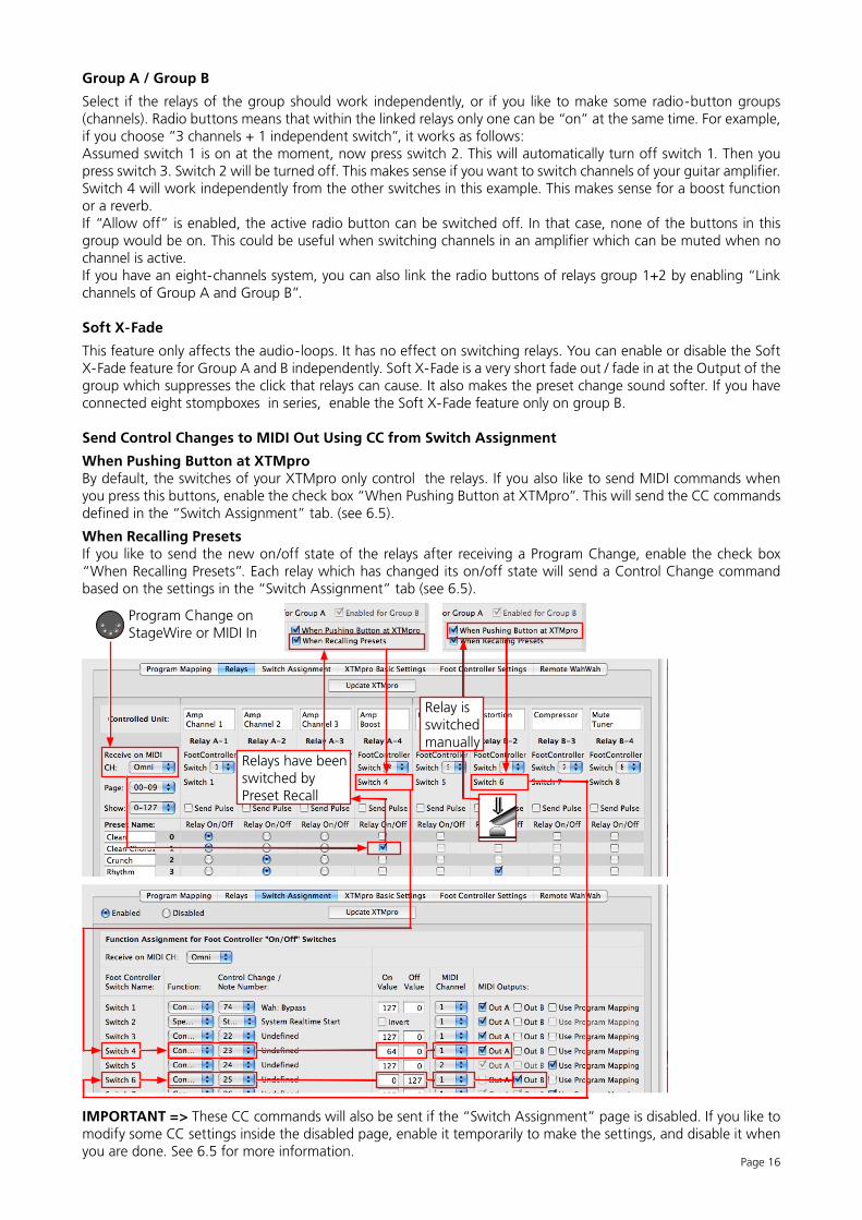
Group A / Group B
Select if the relays of the group should work independently, or if you like to make some radio-button groups (channels). Radio buttons means that within the linked relays only one can be “on” at the same time. For example, if you choose ”3 channels + 1 independent switch”, it works as follows:Assumed switch 1 is on at the moment, now press switch 2. This will automatically turn off switch 1. Then you press switch 3. Switch 2 will be turned off. This makes sense if you want to switch channels of your guitar amplifier. Switch 4 will work independently from the other switches in this example. This makes sense for a boost function or a reverb.If “Allow off” is enabled, the active radio button can be switched off. In that case, none of the buttons in this group would be on. This could be useful when switching channels in an amplifier which can be muted when no channel is active.If you have an eight-channels system, you can also link the radio buttons of relays group 1+2 by enabling “Link channels of Group A and Group B”.
Soft X-Fade
This feature only affects the audio-loops. It has no effect on switching relays. You can enable or disable the Soft X-Fade feature for Group A and B independently. Soft X-Fade is a very short fade out / fade in at the Output of the group which suppresses the click that relays can cause. It also makes the preset change sound softer. If you have connected eight stompboxes in series, enable the Soft X-Fade feature only on group B.
Send Control Changes to MIDI Out Using CC from Switch Assignment
When Pushing Button at XTMproBy default, the switches of your XTMpro only control the relays. If you also like to send MIDI commands when you press this buttons, enable the check box “When Pushing Button at XTMpro”. This will send the CC commands defined in the “Switch Assignment” tab. (see 6.5).
When Recalling PresetsIf you like to send the new on/off state of the relays after receiving a Program Change, enable the check box “When Recalling Presets”. Each relay which has changed its on/off state will send a Control Change command based on the settings in the “Switch Assignment” tab (see 6.5).
IMPORTANT => These CC commands will also be sent if the “Switch Assignment” page is disabled. If you like to modify some CC settings inside the disabled page, enable it temporarily to make the settings, and disable it when you are done. See 6.5 for more information.
Program Change on StageWire or MIDI In
Relays have been switched by Preset Recall
Relay is switched manually
Page 17
6.3 The “Program Mapping” Tab
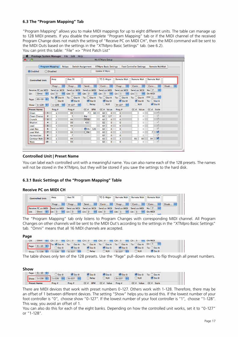
“Program Mapping” allows you to make MIDI mappings for up to eight different units. The table can manage up to 128 MIDI presets. If you disable the complete “Program Mapping” tab or if the MIDI channel of the received Program Change does not match the setting of “Receive PC on MIDI CH”, then the MIDI command will be sent to the MIDI Outs based on the settings in the “XTMpro Basic Settings” tab. (see 6.2). You can print this table: “File” => “Print Patch List”
Controlled Unit | Preset Name
You can label each controlled unit with a meaningful name. You can also name each of the 128 presets. The names will not be stored in the XTMpro, but they will be stored if you save the settings to the hard disk.
6.3.1 Basic Settings of the “Program Mapping” Table
Receive PC on MIDI CH
The “Program Mapping” tab only listens to Program Changes with corresponding MIDI channel. All Program Changes on other channels will be sent to the MIDI Out’s according to the settings in the “XTMpro Basic Settings” tab. “Omni” means that all 16 MIDI channels are accepted.
Page
The table shows only ten of the 128 presets. Use the “Page” pull-down menu to flip through all preset numbers.
Show
There are MIDI devices that work with preset numbers 0-127. Others work with 1-128. Therefore, there may be an offset of 1 between different devices. The setting “Show” helps you to avoid this. If the lowest number of your foot controller is “0”, choose show “0-127”. If the lowest number of your foot controller is “1”, choose “1-128”. This way, you avoid an offset of 1.You can also do this for each of the eight banks. Depending on how the controlled unit works, set it to “0-127” or “1-128”.
5
Page 18
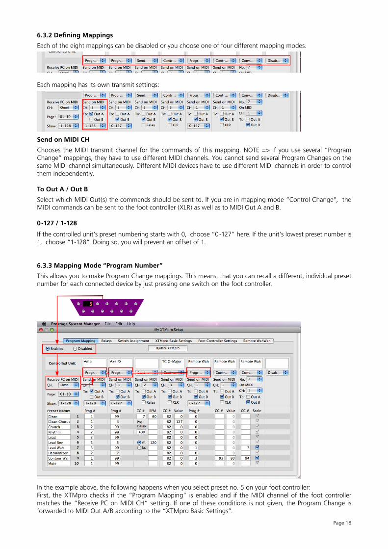
6.3.2 Defining Mappings
Each of the eight mappings can be disabled or you choose one of four different mapping modes.
Each mapping has its own transmit settings:
Send on MIDI CH
Chooses the MIDI transmit channel for the commands of this mapping. NOTE => If you use several “Program Change” mappings, they have to use different MIDI channels. You cannot send several Program Changes on the same MIDI channel simultaneously. Different MIDI devices have to use different MIDI channels in order to control them independently.
To Out A / Out B
Select which MIDI Out(s) the commands should be sent to. If you are in mapping mode “Control Change”, the MIDI commands can be sent to the foot controller (XLR) as well as to MIDI Out A and B.
0-127 / 1-128
If the controlled unit’s preset numbering starts with 0, choose “0-127” here. If the unit’s lowest preset number is 1, choose “1-128”. Doing so, you will prevent an offset of 1.
6.3.3 Mapping Mode “Program Number”
This allows you to make Program Change mappings. This means, that you can recall a different, individual preset number for each connected device by just pressing one switch on the foot controller.
In the example above, the following happens when you select preset no. 5 on your foot controller:First, the XTMpro checks if the “Program Mapping” is enabled and if the MIDI channel of the foot controller matches the “Receive PC on MIDI CH” setting. If one of these conditions is not given, the Program Change is forwarded to MIDI Out A/B according to the “XTMpro Basic Settings”.
5
5
Page 19
If both conditions are true, the following program changes will be sent:Preset no. 3 to Amp (e.g. Lead Channel); Preset no. 99 to Axe FX (e.g. Mute); Preset no. 0 to Remote WahWah (Bypass)
If you, for example, select preset no. 8 at your foot controller, the following presets will be sent:Preset no. 2 to Amp (e.g. Rhythm Channel); Preset no. 7 to Axe FX (e.g. Harmonizer); Preset no. 0 to the Remote WahWah (Bypass)
NOTE => If the box is empty, no preset number will be sent at all.
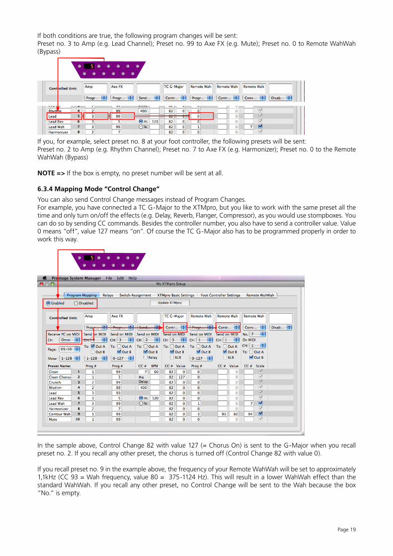
6.3.4 Mapping Mode “Control Change”
You can also send Control Change messages instead of Program Changes.For example, you have connected a TC G-Major to the XTMpro, but you like to work with the same preset all the time and only turn on/off the effects (e.g. Delay, Reverb, Flanger, Compressor), as you would use stompboxes. You can do so by sending CC commands. Besides the controller number, you also have to send a controller value. Value 0 means “off”, value 127 means “on”. Of course the TC G-Major also has to be programmed properly in order to work this way.
In the sample above, Control Change 82 with value 127 (= Chorus On) is sent to the G-Major when you recall preset no. 2. If you recall any other preset, the chorus is turned off (Control Change 82 with value 0).
If you recall preset no. 9 in the example above, the frequency of your Remote WahWah will be set to approximately 1,1kHz (CC 93 = Wah frequency, value 80 = 375-1124 Hz). This will result in a lower WahWah effect than the standard WahWah. If you recall any other preset, no Control Change will be sent to the Wah because the box “No.” is empty.
Page 20
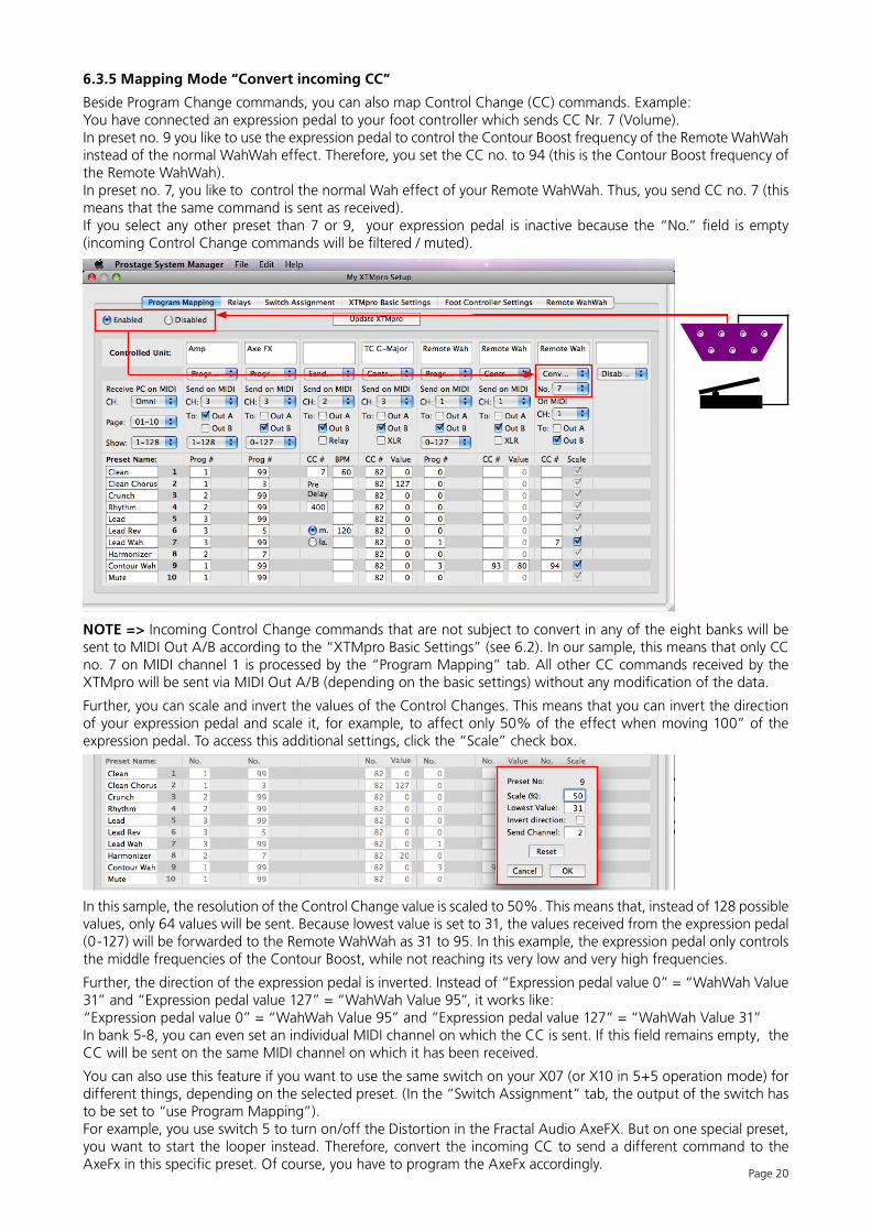
6.3.5 Mapping Mode “Convert incoming CC”
Beside Program Change commands, you can also map Control Change (CC) commands. Example:You have connected an expression pedal to your foot controller which sends CC Nr. 7 (Volume). In preset no. 9 you like to use the expression pedal to control the Contour Boost frequency of the Remote WahWah instead of the normal WahWah effect. Therefore, you set the CC no. to 94 (this is the Contour Boost frequency of the Remote WahWah). In preset no. 7, you like to control the normal Wah effect of your Remote WahWah. Thus, you send CC no. 7 (this means that the same command is sent as received). If you select any other preset than 7 or 9, your expression pedal is inactive because the “No.” field is empty (incoming Control Change commands will be filtered / muted).
NOTE => Incoming Control Change commands that are not subject to convert in any of the eight banks will be sent to MIDI Out A/B according to the “XTMpro Basic Settings” (see 6.2). In our sample, this means that only CC no. 7 on MIDI channel 1 is processed by the “Program Mapping” tab. All other CC commands received by the XTMpro will be sent via MIDI Out A/B (depending on the basic settings) without any modification of the data.
Further, you can scale and invert the values of the Control Changes. This means that you can invert the direction of your expression pedal and scale it, for example, to affect only 50% of the effect when moving 100” of the expression pedal. To access this additional settings, click the “Scale” check box.
In this sample, the resolution of the Control Change value is scaled to 50%. This means that, instead of 128 possible values, only 64 values will be sent. Because lowest value is set to 31, the values received from the expression pedal (0-127) will be forwarded to the Remote WahWah as 31 to 95. In this example, the expression pedal only controls the middle frequencies of the Contour Boost, while not reaching its very low and very high frequencies.
Further, the direction of the expression pedal is inverted. Instead of “Expression pedal value 0” = “WahWah Value 31” and “Expression pedal value 127” = “WahWah Value 95”, it works like:“Expression pedal value 0” = “WahWah Value 95” and “Expression pedal value 127” = “WahWah Value 31”In bank 5-8, you can even set an individual MIDI channel on which the CC is sent. If this field remains empty, the CC will be sent on the same MIDI channel on which it has been received.
You can also use this feature if you want to use the same switch on your X07 (or X10 in 5+5 operation mode) for different things, depending on the selected preset. (In the “Switch Assignment” tab, the output of the switch has to be set to “use Program Mapping”).For example, you use switch 5 to turn on/off the Distortion in the Fractal Audio AxeFX. But on one special preset, you want to start the looper instead. Therefore, convert the incoming CC to send a different command to the AxeFx in this specific preset. Of course, you have to program the AxeFx accordingly.
5
Page 21
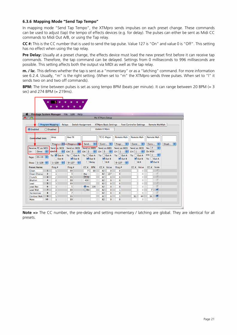
6.3.6 Mapping Mode “Send Tap Tempo”
In mapping mode “Send Tap Tempo”, the XTMpro sends impulses on each preset change. These commands can be used to adjust (tap) the tempo of effects devices (e.g. for delay). The pulses can either be sent as Midi CC commands to Midi Out A/B, or using the Tap relay.
CC #: This is the CC number that is used to send the tap pulse. Value 127 is “On” and value 0 is “Off”. This setting has no effect when using the tap relay.
Pre Delay: Usually at a preset change, the effects device must load the new preset first before it can receive tap commands. Therefore, the tap command can be delayed. Settings from 0 milliseconds to 996 milliseconds are possible. This setting affects both the output via MIDI as well as the tap relay.
m. / la:. This defines whether the tap is sent as a “momentary” or as a “latching” command. For more information see 6.2.4. Usually, “m” is the right setting. (When set to “m” the XTMpro sends three pulses. When set to “l” it sends two on and two off commands).
BPM: The time between pulses is set as song tempo BPM (beats per minute). It can range between 20 BPM (= 3 sec) and 274 BPM (= 219ms).
Note => The CC number, the pre-delay and setting momentary / latching are global. They are identical for all presets.
Page 22
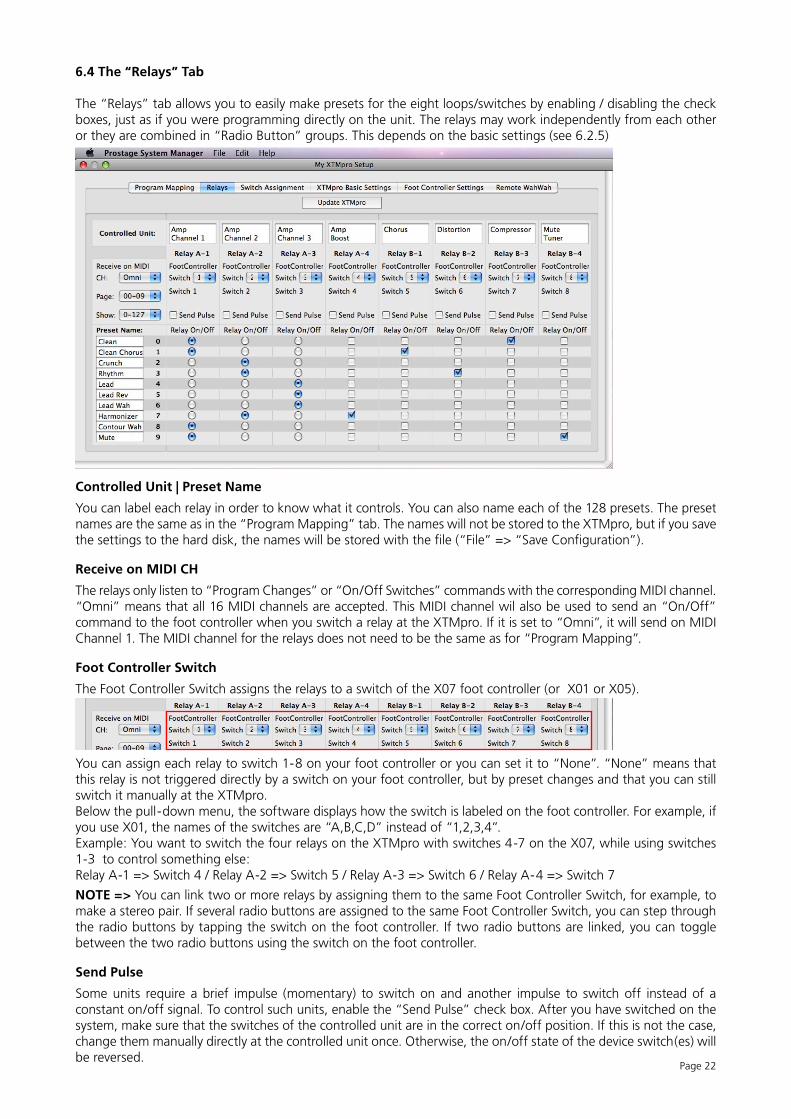
6.4 The “Relays” Tab
The “Relays” tab allows you to easily make presets for the eight loops/switches by enabling / disabling the check boxes, just as if you were programming directly on the unit. The relays may work independently from each other or they are combined in “Radio Button” groups. This depends on the basic settings (see 6.2.5)
Controlled Unit | Preset Name
You can label each relay in order to know what it controls. You can also name each of the 128 presets. The preset names are the same as in the “Program Mapping” tab. The names will not be stored to the XTMpro, but if you save the settings to the hard disk, the names will be stored with the file (“File” => “Save Configuration”).
Receive on MIDI CH
The relays only listen to “Program Changes” or “On/Off Switches” commands with the corresponding MIDI channel. “Omni” means that all 16 MIDI channels are accepted. This MIDI channel wil also be used to send an “On/Off” command to the foot controller when you switch a relay at the XTMpro. If it is set to “Omni”, it will send on MIDI Channel 1. The MIDI channel for the relays does not need to be the same as for “Program Mapping”.
Foot Controller Switch
The Foot Controller Switch assigns the relays to a switch of the X07 foot controller (or X01 or X05).
You can assign each relay to switch 1-8 on your foot controller or you can set it to “None”. “None” means that this relay is not triggered directly by a switch on your foot controller, but by preset changes and that you can still switch it manually at the XTMpro.Below the pull-down menu, the software displays how the switch is labeled on the foot controller. For example, if you use X01, the names of the switches are “A,B,C,D” instead of “1,2,3,4”. Example: You want to switch the four relays on the XTMpro with switches 4-7 on the X07, while using switches 1-3 to control something else:Relay A-1 => Switch 4 / Relay A-2 => Switch 5 / Relay A-3 => Switch 6 / Relay A-4 => Switch 7
NOTE => You can link two or more relays by assigning them to the same Foot Controller Switch, for example, to make a stereo pair. If several radio buttons are assigned to the same Foot Controller Switch, you can step through the radio buttons by tapping the switch on the foot controller. If two radio buttons are linked, you can toggle between the two radio buttons using the switch on the foot controller.
Send Pulse
Some units require a brief impulse (momentary) to switch on and another impulse to switch off instead of a constant on/off signal. To control such units, enable the “Send Pulse” check box. After you have switched on the system, make sure that the switches of the controlled unit are in the correct on/off position. If this is not the case, change them manually directly at the controlled unit once. Otherwise, the on/off state of the device switch(es) will be reversed.
Page 23
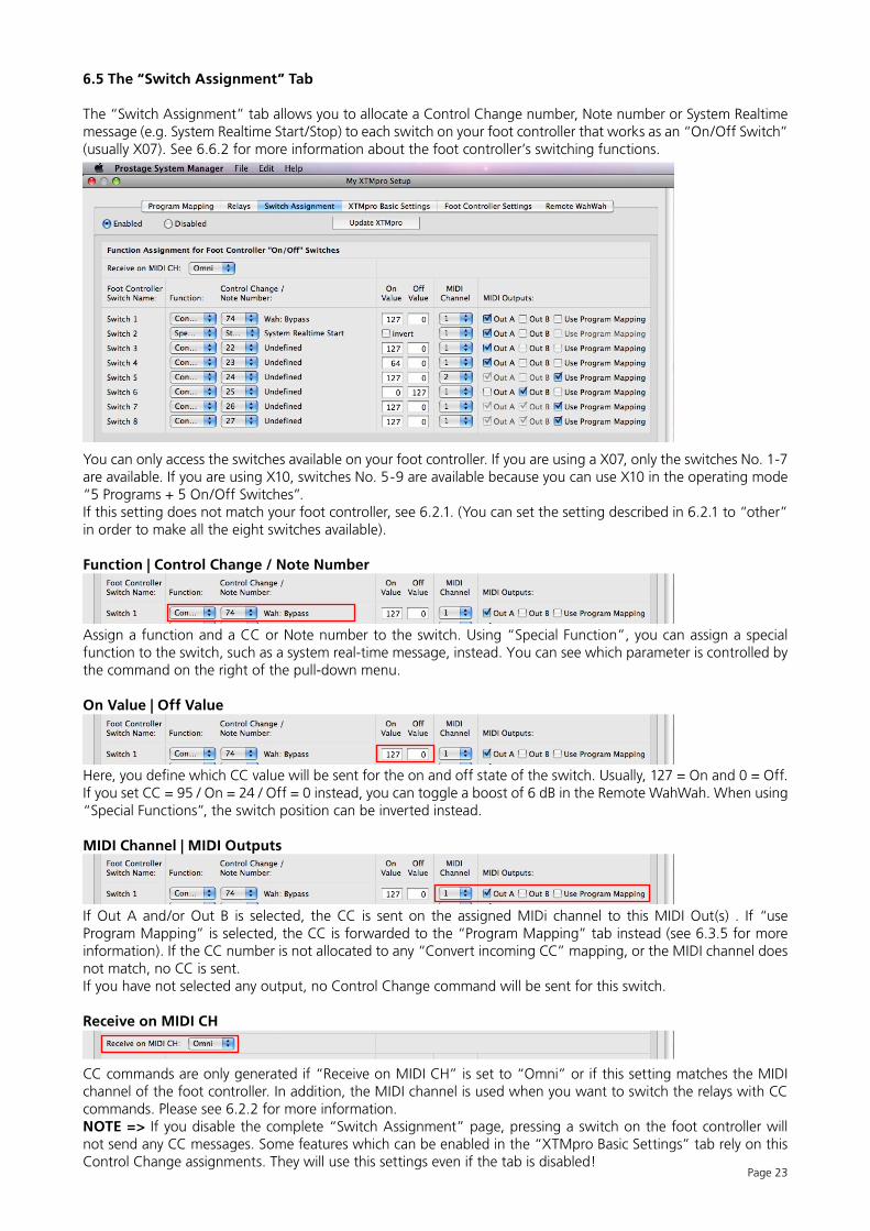
6.5 The “Switch Assignment” Tab
The “Switch Assignment” tab allows you to allocate a Control Change number, Note number or System Realtime message (e.g. System Realtime Start/Stop) to each switch on your foot controller that works as an “On/Off Switch” (usually X07). See 6.6.2 for more information about the foot controller’s switching functions.
You can only access the switches available on your foot controller. If you are using a X07, only the switches No. 1-7 are available. If you are using X10, switches No. 5-9 are available because you can use X10 in the operating mode “5 Programs + 5 On/Off Switches”.If this setting does not match your foot controller, see 6.2.1. (You can set the setting described in 6.2.1 to “other” in order to make all the eight switches available).
Function | Control Change / Note Number
Assign a function and a CC or Note number to the switch. Using “Special Function”, you can assign a special function to the switch, such as a system real-time message, instead. You can see which parameter is controlled by the command on the right of the pull-down menu.
On Value | Off Value
Here, you define which CC value will be sent for the on and off state of the switch. Usually, 127 = On and 0 = Off. If you set CC = 95 / On = 24 / Off = 0 instead, you can toggle a boost of 6 dB in the Remote WahWah. When using “Special Functions”, the switch position can be inverted instead.
MIDI Channel | MIDI Outputs
If Out A and/or Out B is selected, the CC is sent on the assigned MIDi channel to this MIDI Out(s) . If “use Program Mapping” is selected, the CC is forwarded to the “Program Mapping” tab instead (see 6.3.5 for more information). If the CC number is not allocated to any “Convert incoming CC” mapping, or the MIDI channel does not match, no CC is sent.If you have not selected any output, no Control Change command will be sent for this switch.
Receive on MIDI CH
CC commands are only generated if “Receive on MIDI CH” is set to “Omni” or if this setting matches the MIDI channel of the foot controller. In addition, the MIDI channel is used when you want to switch the relays with CC commands. Please see 6.2.2 for more information.NOTE => If you disable the complete “Switch Assignment” page, pressing a switch on the foot controller will not send any CC messages. Some features which can be enabled in the “XTMpro Basic Settings” tab rely on this Control Change assignments. They will use this settings even if the tab is disabled!
Page 24
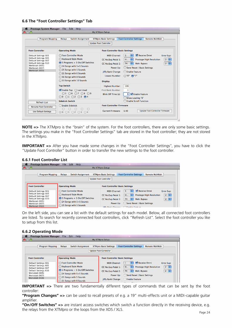
6.6 The “Foot Controller Settings” Tab
NOTE => The XTMpro is the “brain” of the system. For the foot controllers, there are only some basic settings. The settings you make in the “Foot Controller Settings” tab are stored in the foot controller; they are not stored in the XTMpro.
IMPORTANT => After you have made some changes in the “Foot Controller Settings”, you have to click the “Update Foot Controller” button in order to transfer the new settings to the foot controller.
6.6.1 Foot Controller List
On the left side, you can see a list with the default settings for each model. Below, all connected foot controllers are listed. To search for recently connected foot controllers, click “Refresh List”. Select the foot controller you like to setup from this list.
6.6.2 Operating Mode
IMPORTANT => There are two fundamentally different types of commands that can be sent by the foot controller:“Program Changes” => can be used to recall presets of e.g. a 19” multi-effects unit or a MIDI-capable guitar amplifier.“On/Off Switches” => are instant access switches which switch a function directly in the receiving device, e.g. the relays from the XTMpro or the loops from the XDS / XLS.
Page 25
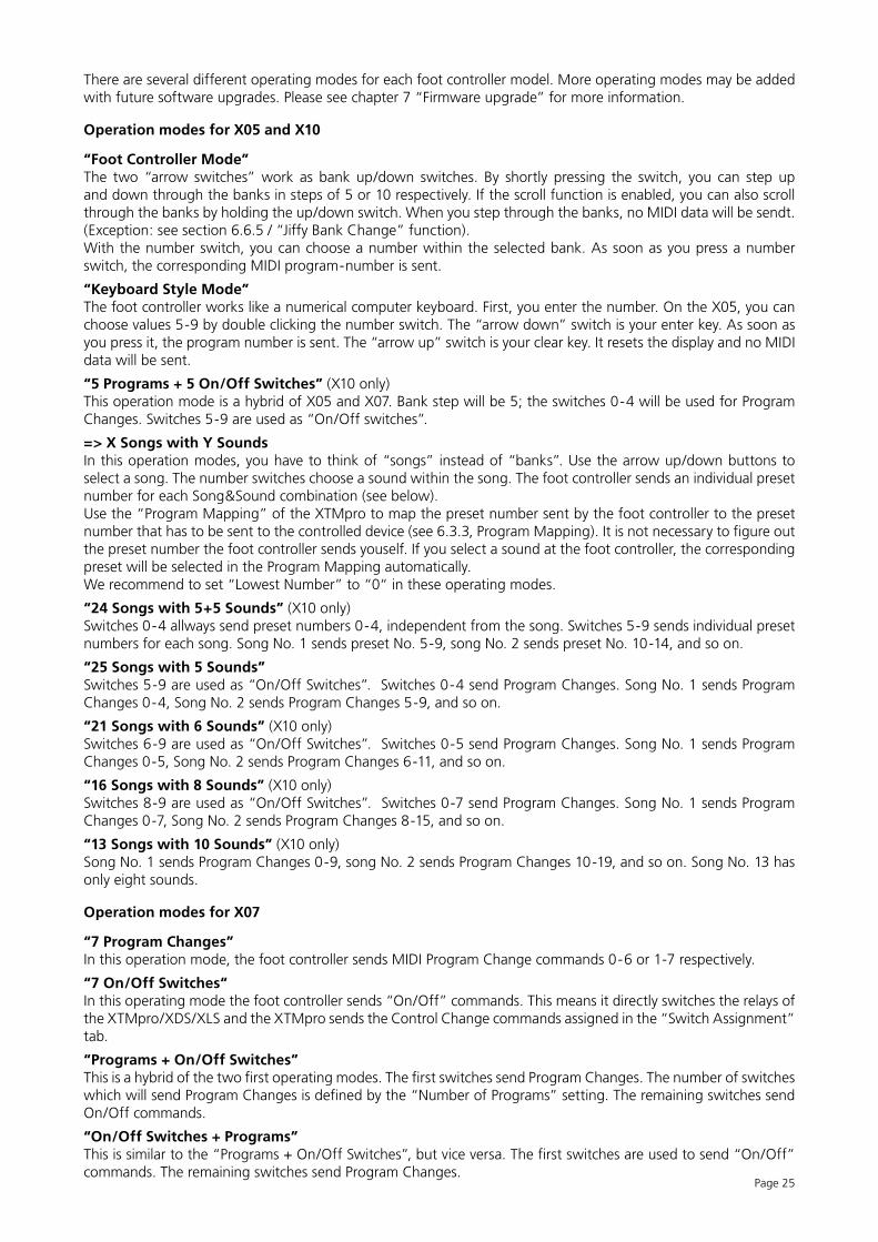
There are several different operating modes for each foot controller model. More operating modes may be added with future software upgrades. Please see chapter 7 “Firmware upgrade” for more information.
Operation modes for X05 and X10
“Foot Controller Mode”The two “arrow switches” work as bank up/down switches. By shortly pressing the switch, you can step up and down through the banks in steps of 5 or 10 respectively. If the scroll function is enabled, you can also scroll through the banks by holding the up/down switch. When you step through the banks, no MIDI data will be sendt. (Exception: see section 6.6.5 / “Jiffy Bank Change” function).With the number switch, you can choose a number within the selected bank. As soon as you press a number switch, the corresponding MIDI program-number is sent.
“Keyboard Style Mode”The foot controller works like a numerical computer keyboard. First, you enter the number. On the X05, you can choose values 5-9 by double clicking the number switch. The “arrow down” switch is your enter key. As soon as you press it, the program number is sent. The “arrow up” switch is your clear key. It resets the display and no MIDI data will be sent.
“5 Programs + 5 On/Off Switches” (X10 only)This operation mode is a hybrid of X05 and X07. Bank step will be 5; the switches 0-4 will be used for Program Changes. Switches 5-9 are used as “On/Off switches”.
=> X Songs with Y SoundsIn this operation modes, you have to think of “songs” instead of “banks”. Use the arrow up/down buttons to select a song. The number switches choose a sound within the song. The foot controller sends an individual preset number for each Song&Sound combination (see below).Use the “Program Mapping” of the XTMpro to map the preset number sent by the foot controller to the preset number that has to be sent to the controlled device (see 6.3.3, Program Mapping). It is not necessary to figure out the preset number the foot controller sends youself. If you select a sound at the foot controller, the corresponding preset will be selected in the Program Mapping automatically.We recommend to set “Lowest Number” to “0“ in these operating modes.
“24 Songs with 5+5 Sounds” (X10 only)Switches 0-4 allways send preset numbers 0-4, independent from the song. Switches 5-9 sends individual preset numbers for each song. Song No. 1 sends preset No. 5-9, song No. 2 sends preset No. 10-14, and so on.
“25 Songs with 5 Sounds” Switches 5-9 are used as “On/Off Switches”. Switches 0-4 send Program Changes. Song No. 1 sends Program Changes 0-4, Song No. 2 sends Program Changes 5-9, and so on.
“21 Songs with 6 Sounds” (X10 only)Switches 6-9 are used as “On/Off Switches”. Switches 0-5 send Program Changes. Song No. 1 sends Program Changes 0-5, Song No. 2 sends Program Changes 6-11, and so on.
“16 Songs with 8 Sounds” (X10 only) Switches 8-9 are used as “On/Off Switches”. Switches 0-7 send Program Changes. Song No. 1 sends Program Changes 0-7, Song No. 2 sends Program Changes 8-15, and so on.
“13 Songs with 10 Sounds” (X10 only)Song No. 1 sends Program Changes 0-9, song No. 2 sends Program Changes 10-19, and so on. Song No. 13 has only eight sounds.
Operation modes for X07
“7 Program Changes”In this operation mode, the foot controller sends MIDI Program Change commands 0-6 or 1-7 respectively.
“7 On/Off Switches“In this operating mode the foot controller sends “On/Off” commands. This means it directly switches the relays of the XTMpro/XDS/XLS and the XTMpro sends the Control Change commands assigned in the “Switch Assignment” tab.
“Programs + On/Off Switches”This is a hybrid of the two first operating modes. The first switches send Program Changes. The number of switches which will send Program Changes is defined by the “Number of Programs” setting. The remaining switches send On/Off commands.
“On/Off Switches + Programs”This is similar to the “Programs + On/Off Switches”, but vice versa. The first switches are used to send “On/Off” commands. The remaining switches send Program Changes.
Page 26
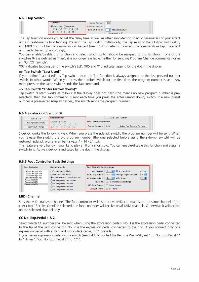
6.6.3 Tap Switch
The Tap function allows you to set the delay time as well as other song-tempo specific parameters of your effect units in real-time by foot tapping. Pressing the Tap switch rhythmically, the Tap relay of the XTMpro will switch, and MIDI Control Change commands can be sent (see 6.2.4 for details). To accept the commands as Tap, the effect unit has to be set up accordingly.You can enable/disable this function and select which switch should be assigned to this function. If one of the switches 0-9 is defined as “Tap”, it is no longer available, neither for sending Program Change commands nor as an “On/Off Switch”. X07 indicates tapping using the switch’s LED. X05 and X10 indicate tapping by the dot in the display.
=> Tap Switch “Last Used”If you define “Last Used” as Tap switch, then the Tap function is always assigned to the last pressed number switch. In other words: When you press the number switch for the first time, the program number is sent. Any more press on the same switch sends the Tap command.
=> Tap Switch “Enter (arrow down)”Tap switch “Enter” works as follows: If the display does not flash (this means no new program number is pre-selected), then the Tap command is sent each time you press the enter (arrow down) switch. If a new preset number is preselected (display flashes), the switch sends the program number.
6.6.4 Sidekick (X05 and X10)
Sidekick works the following way: When you press the sidekick switch, the program number will be sent. When you release the switch, the old program number (the one selected before using the sidekick switch) will be restored. Sidekick works in all banks (e.g. 4 - 14 - 24 ....). This feature is very handy if you like to play a fill or a short solo. You can enable/disable this function and assign a switch to it. Active sidekick is indicated by the dot in the display.
6.6.5 Foot Controller Basic Settings
MIDI Channel
Sets the MIDI-transmit channel. The foot controller will also receive MIDI commands on the same channel. If the check box “Receive Omni” is selected, the foot controller will receive on all MIDI channels. Otherwise, it will receive on the selected channel only.
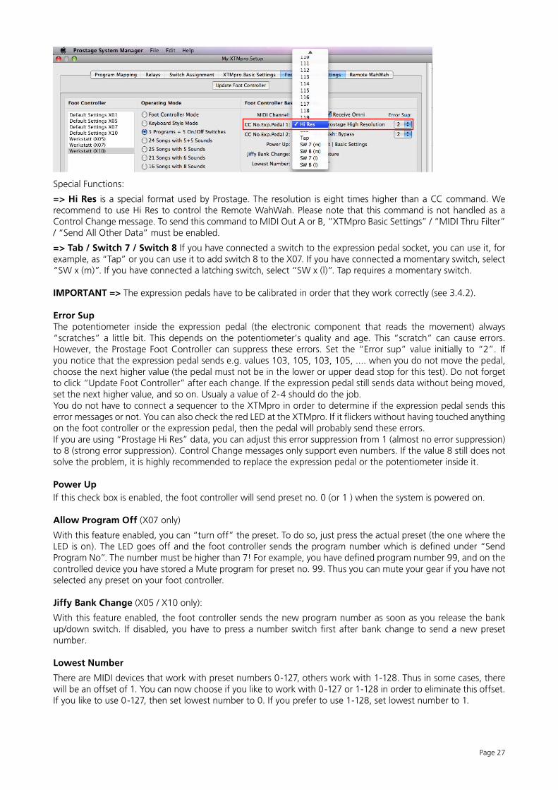
CC No. Exp.Pedal 1 & 2
Select which CC number shall be sent when using the expression pedals. No. 1 is the expression pedal connected to the tip of the Jack connector. No. 2 is the expression pedal connected to the ring. If you connect only one expression pedal with a standard mono-Jack cable, no.1 prevails. If you use an expression pedal with a switch (see 3.4.1) to control the Remote WahWah, set “CC No. Exp. Pedal 1” to “Hi Res”, “CC No. Exp. Pedal 2” to “74”.
Page 27
Special Functions:
=> Hi Res is a special format used by Prostage. The resolution is eight times higher than a CC command. We recommend to use Hi Res to control the Remote WahWah. Please note that this command is not handled as a Control Change message. To send this command to MIDI Out A or B, ”XTMpro Basic Settings” / “MIDI Thru Filter” / “Send All Other Data” must be enabled.
=> Tab / Switch 7 / Switch 8 If you have connected a switch to the expression pedal socket, you can use it, for example, as “Tap” or you can use it to add switch 8 to the X07. If you have connected a momentary switch, select “SW x (m)”. If you have connected a latching switch, select “SW x (l)”. Tap requires a momentary switch.
IMPORTANT => The expression pedals have to be calibrated in order that they work correctly (see 3.4.2).
Error SupThe potentiometer inside the expression pedal (the electronic component that reads the movement) always “scratches” a little bit. This depends on the potentiometer’s quality and age. This “scratch” can cause errors. However, the Prostage Foot Controller can suppress these errors. Set the “Error sup” value initially to “2”. If you notice that the expression pedal sends e.g. values 103, 105, 103, 105, .... when you do not move the pedal, choose the next higher value (the pedal must not be in the lower or upper dead stop for this test). Do not forget to click “Update Foot Controller” after each change. If the expression pedal still sends data without being moved, set the next higher value, and so on. Usualy a value of 2-4 should do the job. You do not have to connect a sequencer to the XTMpro in order to determine if the expression pedal sends this error messages or not. You can also check the red LED at the XTMpro. If it flickers without having touched anything on the foot controller or the expression pedal, then the pedal will probably send these errors.If you are using “Prostage Hi Res” data, you can adjust this error suppression from 1 (almost no error suppression) to 8 (strong error suppression). Control Change messages only support even numbers. If the value 8 still does not solve the problem, it is highly recommended to replace the expression pedal or the potentiometer inside it.
Power UpIf this check box is enabled, the foot controller will send preset no. 0 (or 1 ) when the system is powered on.
Allow Program Off (X07 only)
With this feature enabled, you can “turn off” the preset. To do so, just press the actual preset (the one where the LED is on). The LED goes off and the foot controller sends the program number which is defined under “Send Program No”. The number must be higher than 7! For example, you have defined program number 99, and on the controlled device you have stored a Mute program for preset no. 99. Thus you can mute your gear if you have not selected any preset on your foot controller.
Jiffy Bank Change (X05 / X10 only):
With this feature enabled, the foot controller sends the new program number as soon as you release the bank up/down switch. If disabled, you have to press a number switch first after bank change to send a new preset number.
Lowest Number
There are MIDI devices that work with preset numbers 0-127, others work with 1-128. Thus in some cases, there will be an offset of 1. You can now choose if you like to work with 0-127 or 1-128 in order to eliminate this offset. If you like to use 0-127, then set lowest number to 0. If you prefer to use 1-128, set lowest number to 1.
Page 28
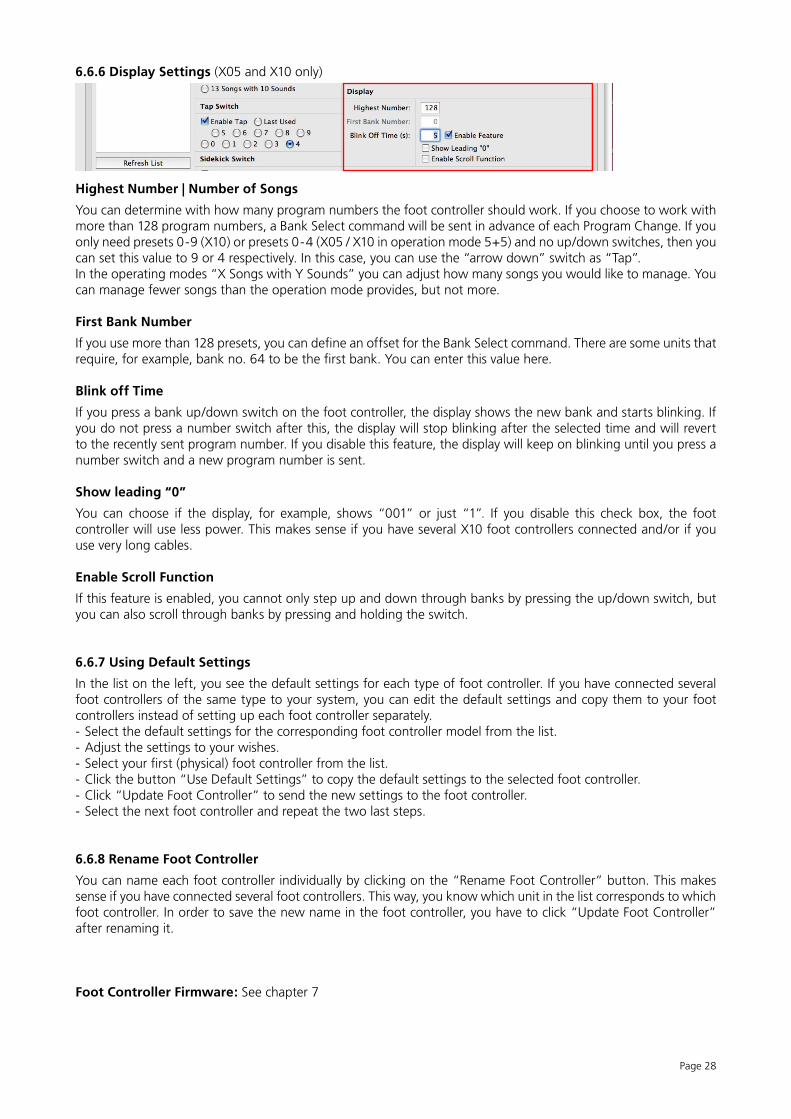
6.6.6 Display Settings (X05 and X10 only)
Highest Number | Number of Songs
You can determine with how many program numbers the foot controller should work. If you choose to work with more than 128 program numbers, a Bank Select command will be sent in advance of each Program Change. If you only need presets 0-9 (X10) or presets 0-4 (X05 / X10 in operation mode 5+5) and no up/down switches, then you can set this value to 9 or 4 respectively. In this case, you can use the “arrow down” switch as “Tap”.In the operating modes “X Songs with Y Sounds” you can adjust how many songs you would like to manage. You can manage fewer songs than the operation mode provides, but not more.
First Bank Number
If you use more than 128 presets, you can define an offset for the Bank Select command. There are some units that require, for example, bank no. 64 to be the first bank. You can enter this value here.
Blink off Time
If you press a bank up/down switch on the foot controller, the display shows the new bank and starts blinking. If you do not press a number switch after this, the display will stop blinking after the selected time and will revert to the recently sent program number. If you disable this feature, the display will keep on blinking until you press a number switch and a new program number is sent.
Show leading “0”
You can choose if the display, for example, shows “001” or just “1”. If you disable this check box, the foot controller will use less power. This makes sense if you have several X10 foot controllers connected and/or if you use very long cables.
Enable Scroll Function
If this feature is enabled, you cannot only step up and down through banks by pressing the up/down switch, but you can also scroll through banks by pressing and holding the switch.
6.6.7 Using Default Settings
In the list on the left, you see the default settings for each type of foot controller. If you have connected several foot controllers of the same type to your system, you can edit the default settings and copy them to your foot controllers instead of setting up each foot controller separately.- Select the default settings for the corresponding foot controller model from the list.- Adjust the settings to your wishes.- Select your first (physical) foot controller from the list.- Click the button “Use Default Settings” to copy the default settings to the selected foot controller.- Click “Update Foot Controller” to send the new settings to the foot controller.- Select the next foot controller and repeat the two last steps.
6.6.8 Rename Foot Controller
You can name each foot controller individually by clicking on the “Rename Foot Controller” button. This makes sense if you have connected several foot controllers. This way, you know which unit in the list corresponds to which foot controller. In order to save the new name in the foot controller, you have to click “Update Foot Controller” after renaming it.
Foot Controller Firmware: See chapter 7
Page 29
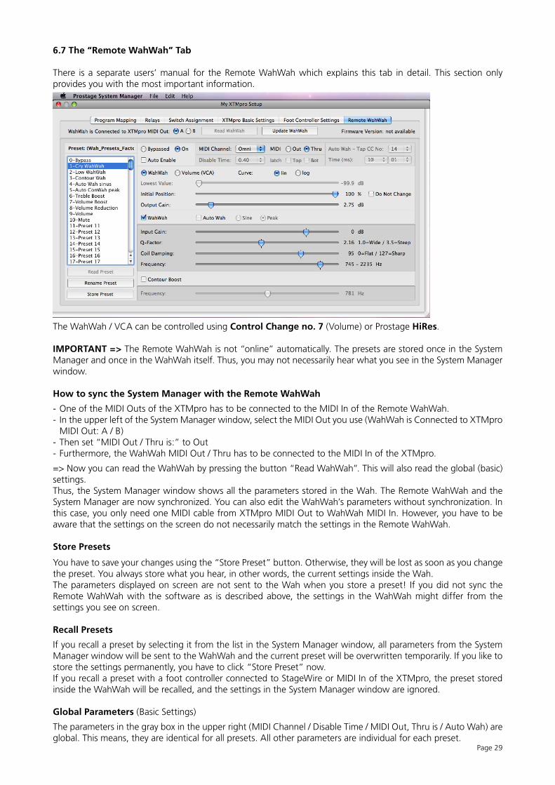
6.7 The “Remote WahWah” Tab
There is a separate users’ manual for the Remote WahWah which explains this tab in detail. This section only provides you with the most important information.
The WahWah / VCA can be controlled using Control Change no. 7 (Volume) or Prostage HiRes.
IMPORTANT => The Remote WahWah is not “online” automatically. The presets are stored once in the System Manager and once in the WahWah itself. Thus, you may not necessarily hear what you see in the System Manager window.
How to sync the System Manager with the Remote WahWah
- One of the MIDI Outs of the XTMpro has to be connected to the MIDI In of the Remote WahWah.- In the upper left of the System Manager window, select the MIDI Out you use (WahWah is Connected to XTMpro
MIDI Out: A / B)- Then set “MIDI Out / Thru is:” to Out- Furthermore, the WahWah MIDI Out / Thru has to be connected to the MIDI In of the XTMpro.
=> Now you can read the WahWah by pressing the button “Read WahWah”. This will also read the global (basic) settings.Thus, the System Manager window shows all the parameters stored in the Wah. The Remote WahWah and the System Manager are now synchronized. You can also edit the WahWah’s parameters without synchronization. In this case, you only need one MIDI cable from XTMpro MIDI Out to WahWah MIDI In. However, you have to be aware that the settings on the screen do not necessarily match the settings in the Remote WahWah.
Store Presets
You have to save your changes using the “Store Preset” button. Otherwise, they will be lost as soon as you change the preset. You always store what you hear, in other words, the current settings inside the Wah. The parameters displayed on screen are not sent to the Wah when you store a preset! If you did not sync the Remote WahWah with the software as is described above, the settings in the WahWah might differ from the settings you see on screen.
Recall Presets
If you recall a preset by selecting it from the list in the System Manager window, all parameters from the System Manager window will be sent to the WahWah and the current preset will be overwritten temporarily. If you like to store the settings permanently, you have to click “Store Preset” now.If you recall a preset with a foot controller connected to StageWire or MIDI In of the XTMpro, the preset stored inside the WahWah will be recalled, and the settings in the System Manager window are ignored.
Global Parameters (Basic Settings)
The parameters in the gray box in the upper right (MIDI Channel / Disable Time / MIDI Out, Thru is / Auto Wah) are global. This means, they are identical for all presets. All other parameters are individual for each preset.
Page 30
7. Firmware Upgrade
The firmware is the operating system; the software inside the XTMpro / foot controller. You can upgrade the firmware yourself. New firmware version brings more functionality to your system.
7.1 How to Upgrade the Firmware of the XTMpro
WARNING: Before upgrading the firmware, please read the settings from the XTMpro and save them to the local hard disk!
- Make sure that the XTMpro is powered on and the USB connection is working properly. - In the System Manager, select the “XTMpro Basic Settings” tab.- On the right side at the bottom, you see which firmware version is currently installed in the XTMpro. If it says
“not available” you have to read the XTMpro first: “File” => “Read XTMpro”.- Check the website “www.prostage.eu => Downloads” for later firmware versions. If there is no higher version,
your XTMpro is already woring with the latest version. Thus, do not proceed the next steps.- Unzip the downloaded .zip file.- Click the button “Update XTMpro Firmware”. An open dialog window appears. Open the file “XTMpro.img”
inside the recently unzipped folder. You are now ready to upgrade the firmware.- Confirm that you like to upgrade the firmware.
IMPORTANT => Neither power-off nor disconnect anything during the upgrading process. This could damage the XTMpro permanently.If the LEDs are blinking crazily after a firmware upgrade, you have to press the relay-button No.1 three times. This will initialize the XTMpro.
7.2 How to Upgrade the Firmware of a Foot Controller
- Make sure that the XTMpro is powered on and that the USB connection is working properly. - Connect ONLY the foot controller to the XTMpro you want to upgrade. Use a short, high quality XLR cable.- Select the “Foot Controller Settings” tab in the System Manager. - Click “Refresh List”- Select the connected foot controller from the list on the left side.- On the right side at the bottom, you can see which firmware version is currently installed in the foot controller- Check the Website “www.prostage.eu => Downloads” for the latest firmware version and download it to your
hard disk. If there is no higher version, your foot controller already uses the latest one. Thus, do not proceed the next steps.
- Unzip the downloaded .zip file. - Click the button “Update Foot Controller Firmware”. An open dialog window appears. Select the recently
unzipped folder. Inside this folder, open the .img file that has the same name as your foot controller model. For example, if you want to upgrade the firmware of X07, choose X07.img. You are now ready to upgrade the firmware. Note: You can only upgrade firmware that matches the type of the connected foot controller.
- Confirm that you want to upgrade the firmware.
IMPORTANT=> Do neither power-off nor disconnect anything during the upgrading process. This could damage the foot controller permanently.If the display (X05 / X10) or the LEDs (X07) are blinking crazily after a firmware upgrade, you have to press the first number switch (X05 / X10 => No. 0; X07 => No. 1) three times. This will initialize the foot controller.
Rel
ays
Pro
gra
m M
app
ing
Swit
ch A
ssig
nm
ent
Bas
ic S
etti
ng
s
Bas
ic
Sett
ing
s
Stag
eW
ire
Switc
hon
/off
?Ta
p Sw
itch?
Prog
ram
Cha
nge
Tabl
een
able
d?
MID
IO
ut
BM
IDI
Ou
t A
Stag
eW
ire
Out
XLR
?O
ut B?O
ut A?
Get
Com
man
d fr
om T
able
Con
trol
Cha
nge
Rece
ive
PC o
nM
IDI C
hann
el?
Map
ping
Mod
e =
Prog
. Num
ber,
Con
trol
C
hang
e or
Tap
Tem
po?
Map
ping
Mod
e =
Con
vert
inco
min
g C
C?
MID
I Out
BM
IDI O
ut A
Rece
ive
onM
IDI C
hann
el?
Prog
ram
Cha
nge
Oth
erC
omm
and
Con
trol
Cha
nge
Mom
enta
ry /
Latc
hing
Logi
cC
C N
o an
d M
IDI
Cha
nnel
mat
ch?
CC
has
bee
n m
appe
d?
only
if M
appi
ng M
ode
=C
ontr
ol C
hang
e
Get
Rel
ays
on/o
ff
stat
e fr
om T
able
Rel
ays
1-8
Get
Foo
t C
on-
trol
ler
Switc
h
Radi
o Bu
tton
& L
ink
Logi
c
Send
Pul
seLo
gic
<=
A
Mid
i thr
u fil
ter
Tap
Out B?
Out A?
Get
Set
tings
fro
m
Tap
Send
as
MID
I
TAP
Rel
ay
Che
ck F
oot
Con
-tr
olle
r Sw
itch
8x
Rece
ive
onM
IDI C
hann
el?
8x
Get
Com
man
dfr
om L
ist
use
Prog
ram
Map
ping
?
Out A?
Out B?<=
A
8x (check all Switches)
Tabl
een
able
d?
(*)
Send
Con
trol
Cha
nges
whe
n re
calli
ng P
rese
ts?
8x (check all Mappings)
Rece
ive
onM
IDI C
hann
el?
(*) i
f a
CC
has
bee
n re
ceiv
ed v
ia M
IDI
In o
r St
ageW
ire a
nd t
he C
C n
um-
ber
is n
ot m
appe
d in
any
of
the
8 m
appi
ngs,
the
orig
inal
CC
is s
ent
to O
ut A
/B b
ased
on
the
XTM
pro
Basi
c Se
ttin
gs.
Bas
ic
Sett
ing
s
Rel
ays
Pro
gra
m M
app
ing
Swit
ch A
ssig
nm
ent
Bas
ic
Sett
ing
s
MID
IIn
use
Prog
ram
Map
ping
?us
e C
C t
osw
itch
Rela
ys?
use
PC t
osw
itch
Rela
ys?
Prog
ram
Cha
nge
Tabl
een
able
d?
MID
IO
ut
BM
IDI
Ou
t A
Stag
eW
ire
TAP
Rel
ayOut
XLR
?O
ut B?O
ut A?
Get
Com
man
d fr
om T
able
Con
trol
Cha
nge
Rece
ive
PC o
nM
IDI C
hann
el?
Map
ping
Mod
e =
Prog
. Num
ber,
Con
trol
C
hang
e or
Tap
Tem
po?
Map
ping
Mod
e =
Con
vert
inco
min
g C
C?
Stag
eW
ire?
Out B?
Out A?
MID
I Out
BM
IDI O
ut A
Con
trol
Cha
nge
Tap
RX
MID
IC
hann
el?
Tap
CC
Num
mer
?
Oth
erC
omm
and
Prog
ram
Cha
nge
Mom
enta
ry /
Latc
hing
Logi
cC
C N
o an
d M
IDI
Cha
nnel
mat
ch?
CC
has
bee
n m
appe
d?
Rel
ays
1-8
<=
A
Proc
ess
Dat
a
Forw
ard
to
Mid
i thr
u fil
ter
Tap
Send
Con
trol
Cha
nges
whe
n re
calli
ng P
rese
ts?
Get
Com
man
dfr
om L
ist
use
Prog
ram
Map
ping
?
Out A?
Out B?<=
A
8x (check all Switches)
Che
ck if
a S
witc
h is
allo
cate
d to
th
e C
C N
o
8x
Rece
ive
onM
IDI C
hann
el?
Get
Rel
ays
on/o
ff
stat
e fr
om T
able
Get
Foo
t C
on-
trol
ler
Switc
h
Send
Pul
seLo
gic
8x
Rece
ive
onM
IDI C
hann
el?
Radi
o Bu
tton
& L
ink
Logi
c
Che
ck F
oot
Con
-tr
olle
r Sw
itch
8x
(*) i
f a
CC
has
bee
n re
ceiv
ed v
ia M
IDI
In o
r St
ageW
ire a
nd t
he C
C n
um-
ber
is n
ot m
appe
d in
any
of
the
8 m
appi
ngs,
the
orig
inal
CC
is s
ent
to O
ut A
/B b
ased
on
the
XTM
pro
Basi
c Se
ttin
gs.
(*)
8x (check all Mappings)
only
if M
appi
ng M
ode
=C
ontr
ol C
hang
e
Switc
h A
ssig
nmen
t do
es o
nly
send
a b
utto
n O
n/O
ff m
es-
sage
to
the
foot
con
trol
ler
if Sw
itch
Ass
ignm
ent a
nd R
elay
s us
e in
divi
dual
Mid
i Cha
nnel
s.
Oth
erw
ise
“Rel
ays”
pre
vails
.
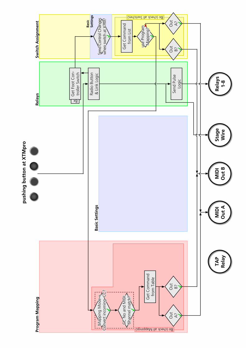
Rel
ays
Swit
ch A
ssig
nm
ent
Bas
ic
Sett
ing
s
Pro
gra
m M
app
ing
Bas
ic S
etti
ng
s
pu
shin
g b
utt
on
at
XTM
pro
MID
IO
ut
BM
IDI
Ou
t A
Stag
eW
ire
Rel
ays
1-8
TAP
Rel
ay
Get
Foo
t C
on-
trol
ler
Switc
h
Radi
o Bu
tton
& L
ink
Logi
c
Send
Pul
seLo
gic
8x
Send
Con
trol
Cha
nges
whe
n sw
itch
at X
TM?
Get
Com
man
dfr
om L
ist
use
Prog
ram
Map
ping
?
Out A?
Out B?
8x (check all Switches)
8x (check all Mappings)
Out B?
Out A?
Get
Com
man
d fr
om T
able
Map
ping
Mod
e =
Con
vert
inco
min
g C
C?
CC
No
and
MID
I C
hann
el m
atch
?
© 2012 Prostage SL
9. Warning Instructions and Warranty
9.1 Warnings and Safety Instructions
For reasons of the product liability, we are obligated to make clear certain safety aspects which must not be ignored under any circumstances. The devices must not be stored or operated in damp or wet environment. Before you connect the XDS or XLS to the power grid, make sure that the tension of the equipment corresponds with the mains voltage of the country-specific grid. If the data of the power grid does not match the data printed on the back of the equipment, it must not be connected to the grid under any circumstances. The power plug of the equipment must be easily accessible so that it can be disconnected from the grid. In addition, we recommend to connect the equipment to a switchable current distribution.The devices serve for routing guitar signals as well as for controlling amplifiers and may be used for this purpose exclusively.The equipment may be opened by qualified technical personnel only. Inside the devices, lethal tensions arise. In addition, there are no user serviceable parts inside the devices.In order to avoid damages, you should be careful when transporting and setting up the devices. Please avoid strong variations in temperature. Particularly the change from the cold transport vehicle to the, usually warm, stage can cause condensing humidity, which can cause leaks and thus can evoke defects. Usually, 60 minutes are sufficient to equalize the temperature. For transportation, always carry the devices in a robust packing/rack, especially in case of a frequently changing place of work.Defect fuses must be replaced by equivalent fuses exclusively. Lower or higher values than indicated on the back of the equipment are inadmissible and can even lead to the destruction of the equipment. For supply of current, only use three-core cables / plugs with earthing contact which are in technically perfect condition.No containers filled with liquid may be placed on the equipment!
9.2. Warranty / Support
All Prostage PurpleLine units are covered by a 2-year warranty. Prostage shall not be liable if the damage was caused by inappropriate use or if the units are not connected like described in this users manual. There are no user serviceable parts inside the units. The detailed terms of the warranty can be downloaded from the Prostage website.
If you need technical support, please contact your local dealer or email to [email protected]
9.3. Disposal of Old Devices
The PurpleLine products are subject to the European guideline 2002/96/EC. All old electric and electronic devices must be disposed separately from the domestic waste, using the collection points provided by the government. The devices may not be disposed with domestic or skip refuse. Information about collecting points or collection dates, can be asked from the local administration or the local waste management company.Please also carry the packing to an environmentally fair disposal. Cardboard boxes can be transferred with wastepaper collections or to the public collecting stations for recycling. Foils of the shipment are collected by the local waste management company and are forwarded to environmentally fair disposal.
Declaration of Conformity
Company: Prostage SL Apdo 57 ES-07560 Cala Millor
Type of equipment: PurpleLine System
Trademarks: Prostage / StageWire
Models: XDS, XLS, XTMpro, X10, X07, X05, X01, XB1
The products meet the requirements of the following standards:
EMC: EN 55103-2 | EN 55103-1:2009 | EN 55103-2:2009 EN 61000-3-2 EN 61000-4-2 | EN 61000-4-3 | EN 61000-4-4 | EN 61000-4-5 | EN 61000-4-3 | EN 61000-4-11Safety: IEC 60065:2001 | EN 60065:2002 / A1:2006 / Cor.:2007 / A11:2008
Year: 2011
Cala Millor, 14. Dezember 2011 Lukas Truninger, CEO
Information to the user: Class B Statement: This equipment has been tested and found to comply with the limits for a Class B digital device, pursuant to part 15 of the FCC Rules. These limits are designed to provide reasonable protection against harmful interference in a residential installation. This equipment generates, uses and can radiate radio frequency energy and, if not installed and used in accordance with the instructions, may cause harmful interference to radio communications. However, there is no guarantee that interference will not occur in a particular installation. If this equipment does cause harmful interference to radio or television reception, which can be determined by turning the equipment off and on, the user is encouraged to try to correct the interference by one or more of the following measures: - Reorient or relocate the receiving antenna. - Increase the separation between the equipment and receiver. - Connect the equipment into an outlet on a circuit different from that to which the receiver is connected. - Consult the dealer or an experienced radio/TV technician for help.