Embed Size (px)
Citation preview
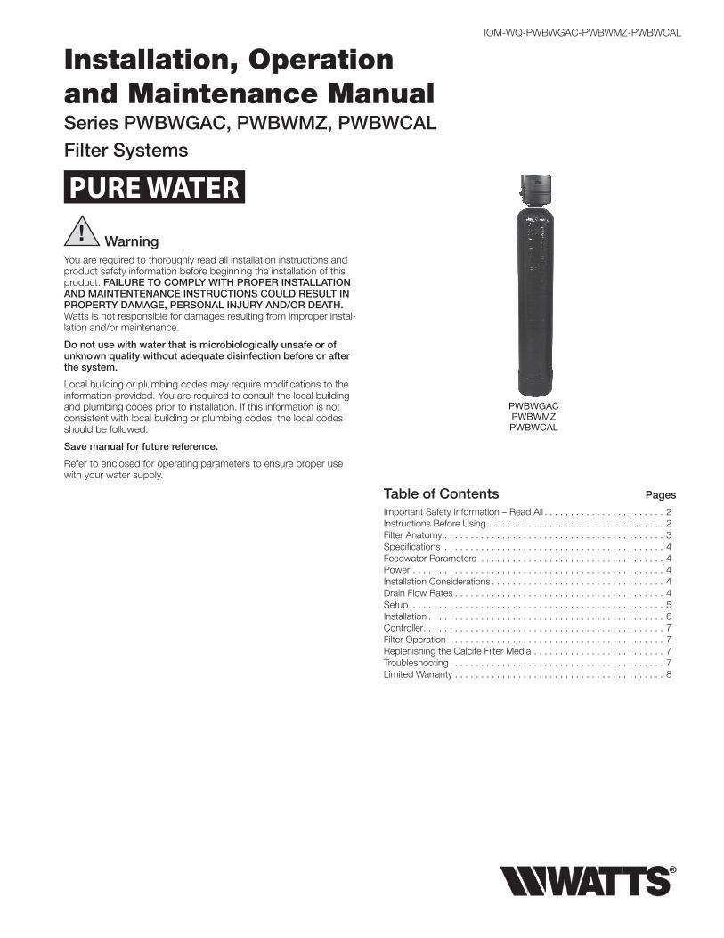
Installation, Operation and Maintenance ManualSeries PWBWGAC, PWBWMZ, PWBWCALFilter Systems
IOM-WQ-PWBWGAC-PWBWMZ-PWBWCAL
! WarningYou are required to thoroughly read all installation instructions and product safety information before beginning the installation of this product. FAILURE TO COMPLY WITH PROPER INSTALLATION AND MAINTENTENANCE INSTRUCTIONS COULD RESULT IN PROPERTY DAMAGE, PERSONAL INJURY AND/OR DEATH. Watts is not responsible for damages resulting from improper instal-lation and/or maintenance.
Do not use with water that is microbiologically unsafe or of unknown quality without adequate disinfection before or after the system.
Local building or plumbing codes may require modifications to the information provided. You are required to consult the local building and plumbing codes prior to installation. If this information is not consistent with local building or plumbing codes, the local codes should be followed.
Save manual for future reference.
Refer to enclosed for operating parameters to ensure proper use with your water supply.
Table of Contents Pages
Important Safety Information – Read All . . . . . . . . . . . . . . . . . . . . . . . 2Instructions Before Using. . . . . . . . . . . . . . . . . . . . . . . . . . . . . . . . . . 2Filter Anatomy . . . . . . . . . . . . . . . . . . . . . . . . . . . . . . . . . . . . . . . . . . 3Specifications . . . . . . . . . . . . . . . . . . . . . . . . . . . . . . . . . . . . . . . . . . 4Feedwater Parameters . . . . . . . . . . . . . . . . . . . . . . . . . . . . . . . . . . . 4Power . . . . . . . . . . . . . . . . . . . . . . . . . . . . . . . . . . . . . . . . . . . . . . . . 4Installation Considerations . . . . . . . . . . . . . . . . . . . . . . . . . . . . . . . . . 4Drain Flow Rates . . . . . . . . . . . . . . . . . . . . . . . . . . . . . . . . . . . . . . . . 4Setup . . . . . . . . . . . . . . . . . . . . . . . . . . . . . . . . . . . . . . . . . . . . . . . . 5Installation . . . . . . . . . . . . . . . . . . . . . . . . . . . . . . . . . . . . . . . . . . . . . 6Controller. . . . . . . . . . . . . . . . . . . . . . . . . . . . . . . . . . . . . . . . . . . . . . 7Filter Operation . . . . . . . . . . . . . . . . . . . . . . . . . . . . . . . . . . . . . . . . . 7Replenishing the Calcite Filter Media . . . . . . . . . . . . . . . . . . . . . . . . . 7Troubleshooting. . . . . . . . . . . . . . . . . . . . . . . . . . . . . . . . . . . . . . . . . 7Limited Warranty . . . . . . . . . . . . . . . . . . . . . . . . . . . . . . . . . . . . . . . . 8
PWBWGAC PWBWMZPWBWCAL
PURE WATER
2
READ Instructions Before Using• After reading these instructions completely, obtain all the
materials and tools needed for installation.
NOTE: Failure to install the system correctly voids the warranty.
• Perform installation according to state, province and local plumbing codes.
Use only lead-free solder and flux for sweat-solder connec-tions, as required by state, province and federal codes.
• Handle all components of the system with care. Do not drop, drag or turn components upside down.
• Be sure the floor under the water filter system is clean, level and strong enough to support the unit.
• The system uses 24 volt-60Hz electrical power. Always use the transformer supplied.
Plug transformer into an indoor 120 VAC, grounded outlet.
Properly ground the system to conform with all codes and ordinances.
• Install the system in a protected area. Be sure electric outlet and transformer do not come in contact with water. For more information on where to install the filter see the Installation Considerations section of this manual.
Do not attempt to treat water over 110°F (43°C) with the system. Always connect the system to the main water sup-ply pipe before the water heater.
Do not expose the system to freezing temperatures. Water freezing in the system causes equipment damage.
Do not install in direct sunlight. Ultraviolet rays from the sun may cause damage.
• Minimum inlet water pressure is 30psi. Maximum inlet water pressure is 125psi. Use a pressure reducing valve if necessary.
!Caution: Read and follow the information in this manual to minimize the risk of electric shock or per-sonal injury.
Important: If you are unsure about installing your Watts water filter, contact a Watts representative or consult a professional plumber.
Important: This system must be installed in compli-ance with applicable state province and local codes, law, and regulations.
!Caution:
• Do not use with water that is microbiologically unsafe or of unknown quality.
• Test the water periodically to verify that the system is performing satisfactorily.
• Discard small parts remaining after the installation.
Important Safety Information – Read All

3
Filter Anatomy
1
2
3
4
5
6
7
Item # DescrIptIon
1 Valve2 Bypass3 Tank4 Distributor5 Filter Media (Calcite, Carbon, or Micro Z™)6 Faceplate/Controls7 Gravel Underbed
4
Specifications
Feed Water Parameters Do not use this system on water that is microbiologically unsafe or of unknown quality without adequate disinfection before or after the system !
Minimum inlet pressure: 30 psig
Maximum operating pressure: 125 psig
Minimum water temperature: 34°F (1°C)
Maximum water temperature: 110°F (43°C)
Power
Voltage: 120VAC
Frequency: 60Hz
Power consumption: 7 Watts Maximum
Installation
Location: Indoors (Protect from direct sunlight)
Minimum ambient temperature: 34°F (1°C)
Maximum ambient temperature: 122°F (50°C)
!
moDeL no. VaLVe mIneraL tank sIze
meDIa cubIc Foot
GraVeL (Lbs)
peak serVIce FLow (Gpm)*
pressure Drop back wash (Gpm)
FLoor space L X w X h
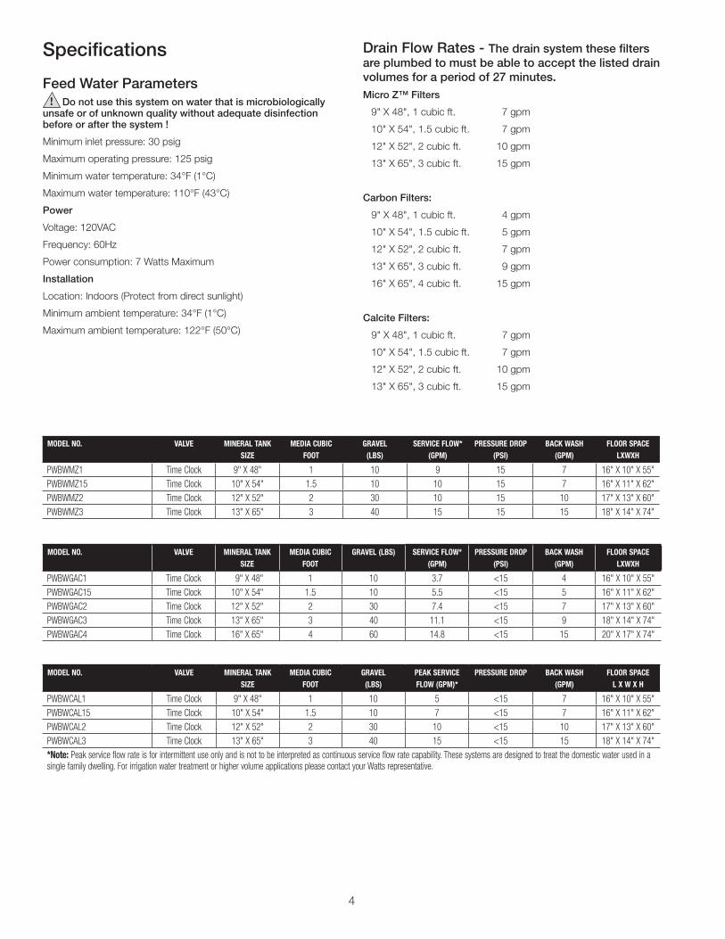
PWBWCAL1 Time Clock 9" X 48" 1 10 5 <15 7 16" X 10" X 55"PWBWCAL15 Time Clock 10" X 54" 1.5 10 7 <15 7 16" X 11" X 62"PWBWCAL2 Time Clock 12" X 52" 2 30 10 <15 10 17" X 13" X 60"PWBWCAL3 Time Clock 13" X 65" 3 40 15 <15 15 18" X 14" X 74"*note: Peak service flow rate is for intermittent use only and is not to be interpreted as continuous service flow rate capability. These systems are designed to treat the domestic water used in a single family dwelling. For irrigation water treatment or higher volume applications please contact your Watts representative.
moDeL no. VaLVe mIneraL tank sIze
meDIa cubIc Foot
GraVeL (Lbs)
serVIce FLow* (Gpm)
pressure Drop (psI)
back wash (Gpm)
FLoor space LXwXh
PWBWMZ1 Time Clock 9" X 48" 1 10 9 15 7 16" X 10" X 55"PWBWMZ15 Time Clock 10" X 54" 1.5 10 10 15 7 16" X 11" X 62"PWBWMZ2 Time Clock 12" X 52" 2 30 10 15 10 17" X 13" X 60"PWBWMZ3 Time Clock 13" X 65" 3 40 15 15 15 18" X 14" X 74"
moDeL no. VaLVe mIneraL tank sIze
meDIa cubIc Foot
GraVeL (Lbs) serVIce FLow* (Gpm)
pressure Drop (psI)
back wash (Gpm)
FLoor space LXwXh
PWBWGAC1 Time Clock 9" X 48" 1 10 3.7 <15 4 16" X 10" X 55"PWBWGAC15 Time Clock 10" X 54" 1.5 10 5.5 <15 5 16" X 11" X 62"PWBWGAC2 Time Clock 12" X 52" 2 30 7.4 <15 7 17" X 13" X 60"PWBWGAC3 Time Clock 13" X 65" 3 40 11.1 <15 9 18" X 14" X 74"PWBWGAC4 Time Clock 16" X 65" 4 60 14.8 <15 15 20" X 17" X 74"
Drain Flow Rates - The drain system these filters are plumbed to must be able to accept the listed drain volumes for a period of 27 minutes.Micro Z™ Filters
9" X 48", 1 cubic ft. 7 gpm
10" X 54", 1.5 cubic ft. 7 gpm
12" X 52", 2 cubic ft. 10 gpm
13" X 65", 3 cubic ft. 15 gpm
Carbon Filters:
9" X 48", 1 cubic ft. 4 gpm
10" X 54", 1.5 cubic ft. 5 gpm
12" X 52", 2 cubic ft. 7 gpm
13" X 65", 3 cubic ft. 9 gpm
16" X 65", 4 cubic ft. 15 gpm
Calcite Filters:
9" X 48", 1 cubic ft. 7 gpm
10" X 54", 1.5 cubic ft. 7 gpm
12" X 52", 2 cubic ft. 10 gpm
13" X 65", 3 cubic ft. 15 gpm
5
SetupUnpack and check the system components for damage or missing parts.
Make sure that the bypass valve and plumbing yoke are properly connected to each other and to the control valve with the mounting clips. Make certain that the drain line flow control fitting is installed properly on the drain port of the control valve. Systems that are 13” in diameter and larger are not loaded with media. These systems must be loaded with media before placing into service. To load a system follow the below steps.
1. Cap the top open end of the distributor tube with tape and plas-tic sheeting to keep foreign debris from entering the distributor tube. This cap must be secure and not come off during media loading.
2. Place the distributor tube, screen end down, into the mineral tank and center it in the bottom. The top of the distributor tube should be flush with the top of the tank.
3. Make sure the plastic and tape cap is secure to the top of the distributor tube, place a funnel on the top of the tank and load first the gravel then the filter media into the tank. The cap must not come off of the distributor tube during the loading of the media.
4. Remove the plastic cap from the distributor tube. DO NOT PULL UP ON THE DISTRIBUTOR TUBE when removing the cap. The distributor tube top must remain flush with the top of the tank.
5. Clean any media from the threads and top of the mineral tank.
6. Lubricate the O-rings on the bottom of the control valve (dis-tributor pilot O-ring and top of tank O-ring). Use non-petroleum based silicone lubricant only.
7. Place the control valve on top of the tank. When doing this step, seat the top of the distributor tube inside the centered O-ring sealed port on the bottom of the valve first then press the valve down until the tank threads come in contact with the valve threads. This ensures that the distributor tube is properly seated into the bottom of the control valve. Thread the valve on to the tank clockwise. Be careful not to cross thread the valve or over tighten it. A hand tight snug fit is appropriate for the control valve torque. A wrench is not necessary. Do not use thread sealant or PTFE tape on the valve base threads.
8. The system is now ready for installation.
Installation ConsiderationsConsider the following points when determining where to install the filter:
• Place the system as close as possible to a sewer drain.
• Do not install the filter where it would block access to the water heater, or access to the main water shutoff, water meter, or electri-cal panels.
• Install the filter in a place where water damage is least likely to oc-cur if a leak develops.
• A 120VAC electrical outlet is needed to plug in the transformer.
• Always connect the system to the main water supply pipe before the water heater.
• Install the system where it will not be subject to temperatures outside of the limits stated in the Specification section or to direct sunlight.
• Make sure the installation surface is smooth, level, and sturdy enough to support the weight of the wetted system.
6
Installation 1. Turn off gas or electric supply to the water heater.
2. Turn off the main water supply to pipes to be cut and drain the house water pipes.
3. Open both hot and cold faucets.
4. Move the filter assembly into installation position.
• Be sure the floor under the water filter system is clean, level and strong enough to support the unit.
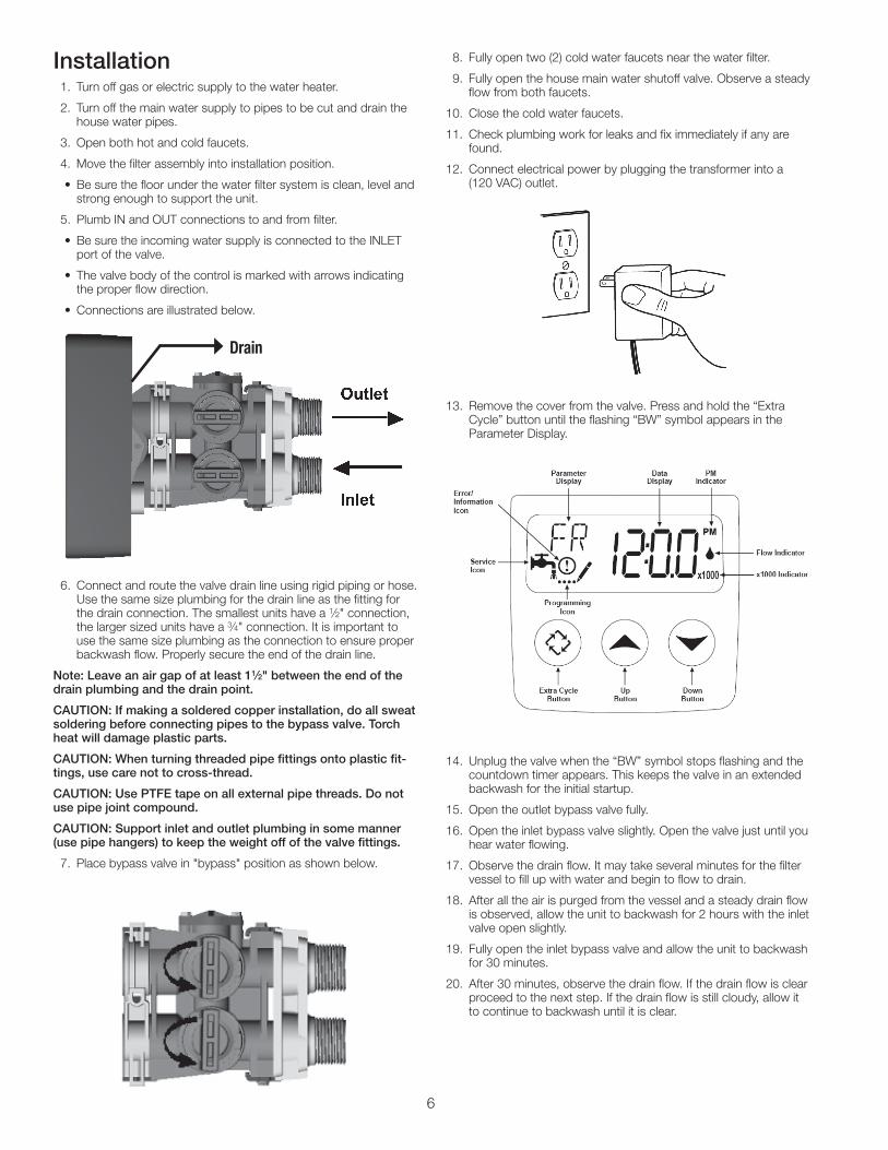
5. Plumb IN and OUT connections to and from filter.
• Be sure the incoming water supply is connected to the INLET port of the valve.
• The valve body of the control is marked with arrows indicating the proper flow direction.
• Connections are illustrated below.
6. Connect and route the valve drain line using rigid piping or hose. Use the same size plumbing for the drain line as the fitting for the drain connection. The smallest units have a 1⁄2" connection, the larger sized units have a 3⁄4" connection. It is important to use the same size plumbing as the connection to ensure proper backwash flow. Properly secure the end of the drain line.
Note: Leave an air gap of at least 11⁄2" between the end of the drain plumbing and the drain point.
CAUTION: If making a soldered copper installation, do all sweat soldering before connecting pipes to the bypass valve. Torch heat will damage plastic parts.
CAUTION: When turning threaded pipe fittings onto plastic fit-tings, use care not to cross-thread.
CAUTION: Use PTFE tape on all external pipe threads. Do not use pipe joint compound.
CAUTION: Support inlet and outlet plumbing in some manner (use pipe hangers) to keep the weight off of the valve fittings.
7. Place bypass valve in "bypass" position as shown below.
8. Fully open two (2) cold water faucets near the water filter.
9. Fully open the house main water shutoff valve. Observe a steady flow from both faucets.
10. Close the cold water faucets.
11. Check plumbing work for leaks and fix immediately if any are found.
12. Connect electrical power by plugging the transformer into a (120 VAC) outlet.
13. Remove the cover from the valve. Press and hold the “Extra Cycle” button until the flashing “BW” symbol appears in the Parameter Display.
14. Unplug the valve when the “BW” symbol stops flashing and the countdown timer appears. This keeps the valve in an extended backwash for the initial startup.
15. Open the outlet bypass valve fully.
16. Open the inlet bypass valve slightly. Open the valve just until you hear water flowing.
17. Observe the drain flow. It may take several minutes for the filter vessel to fill up with water and begin to flow to drain.
18. After all the air is purged from the vessel and a steady drain flow is observed, allow the unit to backwash for 2 hours with the inlet valve open slightly.
19. Fully open the inlet bypass valve and allow the unit to backwash for 30 minutes.
20. After 30 minutes, observe the drain flow. If the drain flow is clear proceed to the next step. If the drain flow is still cloudy, allow it to continue to backwash until it is clear.
Drain
7
Installation continued 22. Plug the unit back in to the electrical outlet and allow it to finish
the flush cycle. This will take approximately 20 minutes.
23. Set the time of day. Press and hold either the Up or Down but-tons until the programming icon replaces the service icon and the parameter display reads TD. Adjust the displayed time with the Up and Down buttons. When the desired time is set, press the Extra Cycle button to resume normal operation. The unit will also return to normal operation after 5 seconds if no buttons are pressed.
24. Turn on the gas or electric supply to the water heater after all air has been purged from the house's plumbing system and water heaters.
ControllerThe factory default program settings should be adequate for most installations. See the ProFlo SXT Service Manual included with the unit for advanced programming options.
Filter OperationAs water enters the filter, it passes through the filter media. Over time, suspended solids accumulate in the filter media and need to be rinsed out. This is accomplished by performing a backwash. During backwash the filter is in automatic bypass allowing unfiltered water to pass downstream. The automatic backwash is initiated based on time and is normally set to occur in the middle of the night.
This System Has Three Positions:1. Backwash Position
Backwash is a rapid upward flow of water that loosens the filter bed and flushes dirt and sediment captured in the bed out to the drain.
2. Fast Rinse Position
Fast Rinse is a fast flow of water down through the filter bed that follows a Backwash. This packs the filter bed for the next service cycle.
3. Service Position
When the filter is In Service, water is flowing through the system and sediment is being removed from your water if it’s a Micro Z™ filter. If it’s a carbon filter, it removes chlorine, tastes, odors, and organics from your water. If your system contains calcite media your water's acidic pH will be raised closer to a value of 7.
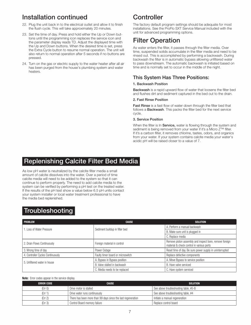
probLem cause soLutIon
1. Loss of Water Pressure Sediment buildup in filter bedA. Perform a manual backwashB. Make sure unit is plugged inC. Replace media
2. Drain Flows Continuously Foreign material in control Remove piston assembly and inspect bore, remove foreign material & check control in various ports
3. Wrong time of day Power Outage Reset time of day. Be sure power supply in uninterrupted4. Controller Cycles Continuously Faulty timer board or microswitch Replace defective components
5. Unfiltered water in house A. Bypass in Bypass position A. Move Bypass to service positionB. Valve stalled in backwash B. Have valve servicedC. Media needs to be replaced C. Have system serviced
error coDe cause soLutIon
(Err 0) Drive motor is stalled See above troubleshooting table, #5-B(Err 1) Drive water runs continuously See above troubleshooting table, #4(Err 2) There has been more than 99 days since the last regeneration Initiate a manual regeneration(Err 3) Control Board memory failure Replace control board
Troubleshooting
Replenishing Calcite Filter Bed MediaAs low pH water is neutralized by the calcite filter media a small amount of calcite dissolves into the water. Over a period of time calcite media will need to be added to the system so that it can continue to perform properly. The need to add calcite media to the system can be verified by performing a pH test on the treated water. If the results of the pH test show a value below 6.5 pH units contact your system installer or local water treatment professional to have the media bed replenished.
note: Error codes appear in the service display.
IOM-WQ-PWBWGAC-PWBWMZ-PWBWCAL 1225 EDP# 2915893 © 2012 Watts
USA: Tel. (800) 224-1299 • www.watts.com Canada: Tel. (888) 208-8927 • www.watts.ca
A Watts Water Technologies Company
LImIteD warrantY: Certain Watts Pure Water products come with a limited warranty from Watts Regulator Co. Other products may have no warranty or are covered by the original manufacturer’s warranty only. For specific product warranty information, please visit www.watts.com or the published literature that comes with your product. Any remedies stated in such warranties are exclusive and are the only remedies for breach of warranty. eXcept For the appLIcabLe proDuct warrantY, IF anY, watts makes no other warrantIes, eXpress or ImpLIeD. to the FuLLest eXtent permItteD bY appLIcabLe Law, watts herebY specIFIcaLLY DIscLaIms aLL other warrantIes, eXpress or ImpLIeD, IncLuDInG but not LImIteD to the ImpLIeD warrantIes oF merchantabILItY anD FItness For a partIcuLar purpose, anD In no eVent shaLL watts be LIabLe, In contract, tort, strIct LIabILItY or unDer anY other LeGaL theorY, For IncIDentaL, InDIrect, specIaL or conseQuentIaL DamaGes, IncLuDInG, wIthout LImItatIon, Lost proFIts or propertY DamaGe, reGarDLess oF whether It was InFormeD about the possIbILItY oF such DamaGes.