Embed Size (px)
Citation preview

Single Color (Black)
Single Color (Black)on Black Background
If you need to use the CSI logo on a non-solidbackground use the Photoshop Layered Files.©2005 Spectra Vision Productions, Inc.
Pure Digital Fiberlink®7500 SeriesDVI and Stereo Audio Transmission over one multimode fiber.
World Headquarters55 Cabot CourtHauppauge, New York 11788 USATel: (631) 273-0404Fax: (631) [email protected]
AsiaCommunications Specialties Pte Ltd100 Beach Road#22-09 Shaw TowerSingapore 189702Tel: +65 6391 8790Fax: +65 6396 [email protected]
commspecial.com
Communications Specialties’ Pure Digital Fiberlink® 7500 User’s Manual
Distribute DVI and stereo
audio over one multimode
fiber with no compression,
scaling, conversions or frame
dropping. The 7500 Series
is feature rich, including our
unique Triple EDID function
and Lock Bandwidth and
Equalization capabilities!

Page 2 Pure Digital Fiberlink® 7500 Series User’s Manual
Pure Digital Fiberlink® 7500 Series
Contents
Welcome . . . . . . . . . . . . . . . . . . . . . . . . . . . . . . . . . . . . . . . . . . . . . . . . . . . . . . . . . . . . . . . . . 3
Features . . . . . . . . . . . . . . . . . . . . . . . . . . . . . . . . . . . . . . . . . . . . . . . . . . . . . . . . . . . . . . . . . . 3
Package Contents . . . . . . . . . . . . . . . . . . . . . . . . . . . . . . . . . . . . . . . . . . . . . . . . . . . . . . . . . 3
Technical Specifications
Model Part Number Specifications . . . . . . . . . . . . . . . . . . . . . . . . . . . . . . . . . . . . 4
Video Specifications . . . . . . . . . . . . . . . . . . . . . . . . . . . . . . . . . . . . . . . . . . . . . . . . . . 4
Audio Specifications. . . . . . . . . . . . . . . . . . . . . . . . . . . . . . . . . . . . . . . . . . . . . . . . . . 4
Optical Specifications . . . . . . . . . . . . . . . . . . . . . . . . . . . . . . . . . . . . . . . . . . . . . . . . 5
Miscellaneous Specifications . . . . . . . . . . . . . . . . . . . . . . . . . . . . . . . . . . . . . . . . . 5
Operating Loss Budgets & Maximum Transmission Distance . . . . . . . . . . . 5
Installation Instructions . . . . . . . . . . . . . . . . . . . . . . . . . . . . . . . . . . . . . . . . . . . . . . . . . . . 7
EDID Switch Settings . . . . . . . . . . . . . . . . . . . . . . . . . . . . . . . . . . . . . . . . . . . . . . . . . . . . . . 7
Triple EDID Function . . . . . . . . . . . . . . . . . . . . . . . . . . . . . . . . . . . . . . . . . . . . . . . . . . . . . . 8
Lock Bandwidth & Input Equalization . . . . . . . . . . . . . . . . . . . . . . . . . . . . . . . . . . . . . 10
System Connections . . . . . . . . . . . . . . . . . . . . . . . . . . . . . . . . . . . . . . . . . . . . . . . . . . . . . 11
Alarm Switch Settings & Options . . . . . . . . . . . . . . . . . . . . . . . . . . . . . . . . . . . . . . . . . 12
Indicator LEDs . . . . . . . . . . . . . . . . . . . . . . . . . . . . . . . . . . . . . . . . . . . . . . . . . . . . . . . . . . . 13
Typical Application Diagrams. . . . . . . . . . . . . . . . . . . . . . . . . . . . . . . . . . . . . . . . . . . . . 14
Operating Pointers . . . . . . . . . . . . . . . . . . . . . . . . . . . . . . . . . . . . . . . . . . . . . . . . . . . . . . . 15
Troubleshooting . . . . . . . . . . . . . . . . . . . . . . . . . . . . . . . . . . . . . . . . . . . . . . . . . . . . . . . . . 15
Maintenance and Repairs . . . . . . . . . . . . . . . . . . . . . . . . . . . . . . . . . . . . . . . . . . . . . . . . 16
Certifications . . . . . . . . . . . . . . . . . . . . . . . . . . . . . . . . . . . . . . . . . . . . . . . . . . . . . . . . . . . . 16
Warranty . . . . . . . . . . . . . . . . . . . . . . . . . . . . . . . . . . . . . . . . . . . . . . . . . . . . . . . . . . . . . . . . 17
Accessories and Related Products . . . . . . . . . . . . . . . . . . . . . . . . . . . . . . . . . . . . . . . . 18
Contents

Page 3Pure Digital Fiberlink® 7500 Series User’s Manual
Pure Digital Fiberlink® 7500 Series
WelcomeThank you for purchasing Communications Specialties, Inc.’s Pure Digital Fiberlink® 7500
Series. The 7500 Series is used to transmit pristine DVI and stereo audio over a single fiber
optic core. Compatible with multimode fiber, the 7500 is ideal for the most demanding of
applications, from distance learning to rental and staging. The 7500 offers a unique Triple
EDID function that allows you to generate EDID internally, from a loop-through monitor or
you can permanently capture and store EDID information.
Features • Supports DVI-D single-link resolutions up to 1920 x 1200 at 165 MHz pixel clock
and HDTV resolutions of 480p, 1080i, and 1080p (DVI format)
• Transmits single-link DVI (640 x 480 up to 1920 x 1200 - 165 MHz pixel clock)
• Dual Optical Output multimode version available. (Model 7502)
• Supports HDTV resolutions of 480p, 720p, 1080i and 1080p (DVI format)
• Uses no compression, color space conversion, frame dropping or scaling
for crystal clear signals
• Only one fiber used - no pixel skewing
• Supports up to 45 foot (13.72m) DVI input cable
• DVI Input loop-through
• Supports EDID from loop-through, internal generation, or capture and storage.
• Requires no adjustments, equalization or de-skewing during installation
• Advanced input circuit equalizes and re-clocks noisy and distorted DVI input signals
• Two DVI outputs on box receiver allows for driving two monitors
• Transmits signals over one multimode fiber optic core.
• Low audio/video skew, <300 uSec
• Complete, ready-to-install kits are available for both Box and Card versions
• RoHS Compliant
Package Contents • One Pure Digital Fiberlink® 7500, 7501 or 7502.
• This User’s Manual
Welcome | Features | Package Contents

Page 4 Pure Digital Fiberlink® 7500 Series User’s Manual
Pure Digital Fiberlink® 7500 Series
Model Part Number Specification
Unit Type Part Number
Multimode Transmitter Box 7500-B1SMultimode Transmitter Card 7500-C1SMultimode Receiver Box 7501-B1SMultimode Receiver Card 7501-C1SMultimode Dual Optical Output 7502-B1S Transmitter Box Multimode Dual Optical Output Transmitter Card 7502-C1S
Video
Number of Video Channels 1 single-link DVI up to 1920x1200Video Processing 24 bits, no compression or scalingDVI Input Loop-through YesEDID (DDC) Support Yes, from loop-through, internal generation, or storage and capturePixel Clock Range 25 - 165 Mhz, continuousScanning System Supported Progressive or InterlacedFormat Supported RGB or YPrPb
Audio Specifications
Number of Audio Channels 2, unbalancedFrequency Response +0/-0.5 dB, 20 Hz to 20 kHzBits-per-Sample/Sampling Rate 24 bits; >48kHzMaximum Audio Level +10 dBuSNR (A-Weighted) 100 dB
Technical Specifications
Technical Specifications

Page 5Pure Digital Fiberlink® 7500 Series User’s Manual
Pure Digital Fiberlink® 7500 Series
Audio Specifications (cont.)
THD+N 0.001%, 20 Hz - 20 kHzChannel Phase Differential +0.1ºCrosstalk 100 dB (1 kHz)Input Impedance >24 k OhmsOutput Impedance < 1 OhmAudio to Video Diff. Delay (skew) < 300 uSec
Optical Specifications:
Operating Wavelength MM CWDM (850nm band )Optical Fibers MM: 50u or 62.5u Optical Connector 7500/7501: ST x 1; 7502: ST x 2Class I Laser Product complies with FDA performance standard for laser products, Title 21, Code of Federal Regulations, Sub-Chapter J.
Miscellaneous
Operating Temp. Range -20ºC to +50ºCOperating Power 9-24 Volts AC or DC @ 10 watts (max.)Slots filled in 6000A Card Cage 3
Operating Loss Budget & Maximum Transmission Distance*
Multimode Version 0-8 dB up to 0.75 km; 50u fiber 0-8 dB up to 0.35 km; 62.5u fiberMultimode Dual Optical Output Version 0-4 dB up to 0.60 km; 50u fiber 0-4 dB up to 0.30 km; 62.5u fiber * Distance specifications are approximate and are not guaranteed. Operating loss budget must not be exceeded.
Technical Specifications
Technical Specifications
Page 6 Pure Digital Fiberlink® 7500 Series User’s Manual
Pure Digital Fiberlink® 7500 Series
Installation InstructionsThe Pure Digital Fiberlink® 7500 Series of fiber optic transmission systems are ready for
immediate use and do not require any special tools or equipment. However, an Optical
Power Meter, such as the Fiberlink® 6615, can be useful in determining optical loss budgets
during your systems design and system maintenance.
The following instructions describe the typical installation procedure:
1) Power off your computer and the 7500 Series units.
2) Connect the DVI video source (Computer) to the video input DVI-D
connector on the transmitter unit.
3) Determine your EDID requirements and follow the procedures described in the
“Triple EDID Function” section of this manual.
4) Connect the video output(s) on the receiver unit to the DVI-D connector(s).
5) Connect the fiber optic cable between the two Pure Digital Fiberlink units.
6) Connect the audio input signals to the transmitter stereo jack and the
audio output to the receiver stereo jack.
7) Apply power to both the Pure Digital Fiberlink units and the computer.
For box versions using DC power connections, refer to Figure 1.
8) When power is applied, the green POWER LED will light, indicating the presence
of operating power. The VIDEO LED will give an indication as described on page 13.
The green AUDIO LED will give an indication as stated on page 13.
9) The system should now be operational.
Note: The Rack Card version has an additional red LED for indicating the presence of an alarm condition (loss of signal). Refer to Indicator LED’s and Alarm Switch Settings & Options sections of this manual.
Installation Instructions
The transmitting element in the Pure Digital Fiberlink® 7500 transmitter unit contains a solid state Laser Diode located in the optical connector. This device emits invisible infrared electromagnetic radiation which can be harmful to human eyes. The radiation from this optical connector, if viewed at close range with no fiber optic cable connected to the opti-cal connector, may be sufficient intensity to cause instanta-neous damage to the retina of the eye. Direct viewing of this radiation should be avoided at all times!

Page 7Pure Digital Fiberlink® 7500 Series User’s Manual
Pure Digital Fiberlink® 7500 Series
Installation Instructions (cont.)
Installation Instructions | EDID Switch Settings
Figure 1:
Power Connector
DC Input Polarity 9-24 Volts AC or DC
( - ) Negative
(+) Positive
EDID Switch Settings
Internal When the switch is in this position, the EDID will be automatically generated. Alternatively, if EDID information was previously captured and stored, the unit will use the stored information.Loop The EDID information will be passed through to the DVI source from the display connected to the loop-through port of the unit. If no loop-through display is connected, the DVI source may not generate a DVI signal.
EDID Switch SettingsThe EDID Switch has two positions, Internal and Loop, as described in the chart below. For
complete instructions on how to operate the 7500 Series’ Triple EDID function, please refer
to the “Triple EDID Function” section of this manual on page 8.

Page 8 Pure Digital Fiberlink® 7500 Series User’s Manual
Pure Digital Fiberlink® 7500 Series
Triple EDID Function
The Pure Digital Fiberlink® 7500 Series of fiber optic transmission systems come with a unique “Triple EDID” feature set that allows you to capture and store EDID information, acquire EDID information from a connected loop-through display, or allow the 7500 or 7502 unit to generate the EDID internally, on-the-fly. The procedure for implementing each are described below.
Generating EDID internally when no EDID has been stored:1) Power off your computer and the 7500 Series units.2) Set the EDID switch to the “Internal” position.3) Any DVI display can optionally be connected to the loop-through port of the 7500 or 7502.4) Power on your 7500 or 7502 Transmitter unit and the loop-through display.5) Power on your computer.6) The 7500 or 7502 is now operation and will generate EDID internally.
Using EDID from a loop-through display:1) Power off your computer and the 7500 Series units.2) Set the EDID switch to the “Loop” position.3) Connect a display to the 7500 or 7502 loop-through port.4) Power on your 7500 or 7502 Transmitter unit and the loop-through display.5) Power on your computer.6) The 7500 or 7502 is now operational and will use the EDID information acquired from the loop-through display.
Capturing and storing EDID information:1) Power off your computer and the 7500 Series units.2) Set the EDID switch to the “Loop” position.3) Connect a display to the 7500 or 7502 loop-through port.4) Power on the loop-through display.5) Power on your 7500 or 7502 Transmitter unit.6) Press the ‘Capture EDID’ button on the Transmitter as shown in Figure 2. The Video LED will flash, indicating the capture is in progress. Note that any previously stored EDID information will be overwritten.7) When the Video LED remains off, the capture is complete.Note: This procedure will erase any previously stored EDID information.
Triple EDID Function
Page 9Pure Digital Fiberlink® 7500 Series User’s Manual
Pure Digital Fiberlink® 7500 Series
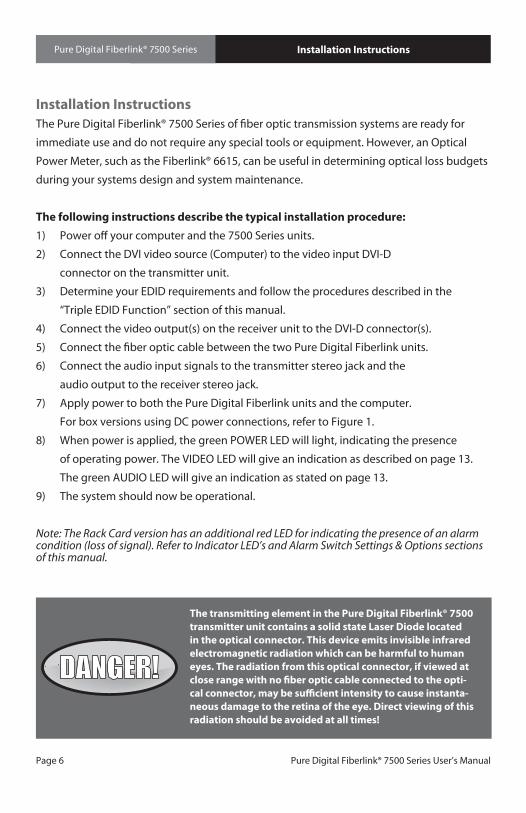
Triple EDID Function (cont.)
Using stored EDID information:Before you can use a stored EDID setting, you must capture and store EDID information as described in the “Capturing and storing EDID information” procedure.1) Power off your computer and the 7500 Series units.2) Set the EDID switch to the “Internal” position.3) Any DVI display can be connected to the loop-through port of the 7500 or 7502.4) Power on your 7500 or 7502 Transmitter unit.5) Power on your computer.6) The 7500 or 7502 will now be using the stored EDID information.
Reseting back to factory defaults when EDID has been previously stored:1) Power off your computer and the 7500 Series units.2) Set the EDID switch to the “Internal” position.3) Disconnect any display from the 7500 or 7502 loop-through port.4) Power on your 7500 or 7502 Transmitter unit.5) Press the ‘Capture EDID’ button to erase stored EDID information as shown in Figure 2.6) The Audio LED should flash for confirmation.7) Power on your computer.
8) The 7500 or 7502 is now operational and will generate EDID internally.
Operating Tips:The 7500 and 7502 transmitter units can be temporarily power using a 9V battery making it very easy to bring the transmitter to a ceiling mounted projector for EDID capture and storage!
If you receive unexpected display results, you may be operating the 7500 or 7502 using EDID information that was stored during a previous installation. Try clearing any stored EDID information.
Triple EDID Function
Figure 2:7500 Box Version Panel PowerCapture
EDIDVideo Audio Optical BW EQ
1 2 3 4

Page 10 Pure Digital Fiberlink® 7500 Series User’s Manual
Pure Digital Fiberlink® 7500 Series Lock Bandwidth & Input Equalization
Lock Bandwidth and Input EqualizationThe 7500 and 7502 transmitter units have a Lock Bandwidth (BW) and Input Equalizer (EQ)
Setting Dip switches located on the front panel. The default factory settings is all switches
in the up position. The default equalizer (EQ) setting is for a short DVI cable, less than 10
feet. The default Bandwidth (BW) setting is WIDE BW. This should work for most clean,
“noise-free” DVI sources. A narrow bandwidth setting should be used for dirty or noisy DVI
sources.
Factory Default:
All Switches in the up position
Lock Bandwidth:
Switches 1 and 2 control the Lock Bandwidth:
Input Equalization:
Switches 3 and 4 control the Input Equalization:
Wide Medium Narrow Very Narrow
Short Medium Long Very Long
BW EQ
1 2 3 4
BW EQ
1 2 3 4
BW EQ
1 2 3 4
BW EQ
1 2 3 4
BW EQ
1 2 3 4
BW EQ
1 2 3 4
BW EQ
1 2 3 4
BW EQ
1 2 3 4
BW EQ
1 2 3 4
Page 11Pure Digital Fiberlink® 7500 Series User’s Manual
Pure Digital Fiberlink® 7500 Series System Connections
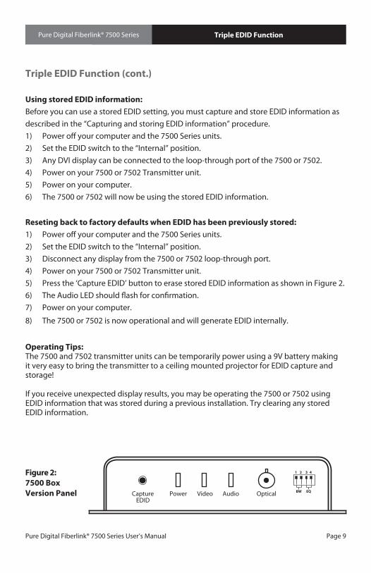
Video Connector
Video Pin Out Transmitter Receiver
1 Red (-) Red (-)
2 Red (+) Red (+)
3 Red Shield Red Shield
4 N/C N/C
5 N/C N/C
6 DDC CLK DDC CLK
7 DDC Data DDC Data
8 N/C N/C
9 Green (-) Green(-)
10 Green (+) Green (+)
11 Green Shield Green Shield
12 N/C N/C
13 N/C N/C
14 +5V Power +5V Power
15 GND (for +5V) GND (for +5V)
16 Hot Plug Detect Hot Plug Detect
17 Blue (-) Blue (-)
18 Blue (+) Blue (+)
19 Blue Shield Blue Shield
20 N/C N/C
21 N/C N/C
22 Pixel Click Shield Pixel Click Shield
23 Pixel Click (+) Pixel Click (+)
24 Pixel Click (-) Pixel Click (-)
System ConnectionsThe input and output connections for the Pure Digital Fiberlink 7500 Series are as follows:
Audio Connector (Transmitter & Receiver): 3.5mm stereo jack
Video Connector (Transmitter & Receiver): DVI-D connector

Page 12 Pure Digital Fiberlink® 7500 Series User’s Manual
Pure Digital Fiberlink® 7500 Series
Alarm Switch Settings for the Transmitter Card
Switch Position Alarm Indication On Off
1 Loss of DVI Signal Enabled Disabled
2 N/A N/A N/A
Alarm Switch Settings for the Receiver Card
Switch Position Alarm Indication On Off
1 Loss of Optical Signal Enabled Disabled
2 N/A N/A N/A
Alarm Switch Settings & OptionsThe Rack Card version of this product has an additional red indicator LED that illuminates
when an alarm condition exists.
The rack card unit also provides an output to drive a model 6020 Alarm Sensing Module
which provides an audible tone and activates a set of contacts for external signaling
purposes.
Alarm Switch Settings & Options

Page 13Pure Digital Fiberlink® 7500 Series User’s Manual
Pure Digital Fiberlink® 7500 Series
Transmitter LEDs
LED Status Definition
Power On Indicates that correct power has been applied.
Video Off Indicates that no proper DVI signal is present On Indicates that a proper DVI signal is present
Audio Off Indicates no audio is present Blinking Indicates audio is present
Alarm On Loss of video (card version only)
Receiver LEDs
LED Status Definition
Power On Indicates that correct power has been applied.
Video Off Indicates that no proper DVI signal is present On Indicates that a proper DVI signal is present
Audio Off Indicates that no audio is present Blinking Indicates audio is present
Alarm On Loss of video (card version only)
Indicator LEDsThe Pure Digital Fiberlink® 7500 Series has three integral indicator LEDs that are used to
monitor the state of the unit. Card versions have an additional Alarm LED.
Indicator LEDs

Page 14 Pure Digital Fiberlink® 7500 Series User’s Manual
Pure Digital Fiberlink® 7500 Series
Basic Configuration:
Advanced Configuration:
Typical Application Diagrams
Loop-throughDVI Monitor
Multimode Fiber
Two DVI displays with audio
DVI Source 7500 Tx 7501Rx
Loop-throughDVI Monitor
Multimode Fiber
One Projector and One DVI
display
Two DVI displays with audio
DVI Source 7502 Tx 7501Rx
7501Rx
Multimode Fiber
Using stored EDID captured from Projector
Using EDID from Display
Note: Both optical outputs of the 7502 Transmitter operate at the same wavelength. For example, you cannot use single mode fiber for optical output #1 and multimode fiber for optical output #2.

Page 15Pure Digital Fiberlink® 7500 Series User’s Manual
Pure Digital Fiberlink® 7500 Series
Operating PointersThe 7500 Series is available in versions that operate with multimode (MM, 62.5u, 50u)
optical fibers. Be certain that the correct size fiber is being used for this particular
transmitter/receiver combination.
Also, remember to check attenuation and bandwidth of the fiber optic cable. The system
will only operate properly if these specifications fall within the range of the system’s loss
budget.
TroubleshootingMultimode fiber optic cable contains an optical fiber with alight carrying “core” that is
only .0025 inches (62.5 microns) in diameter. Single mode fiber optic cable has an even
smaller “core,” only .00032 to .0004 inches (8-10 microns). This is smaller than a human hair!
Therefore, any minute particles of dirt or dust can easily block the fiber from accepting or
radiating light. To prevent this from happening, always use the provided dust caps when
ever optical connectors are exposed to air. It is also a good idea to gently clean the tip of an
optical connector with a lint-free cloth moistened with alcohol whenever dust is suspected.
The status of the LEDs should provide the first clue as to the origin of any operational
failure. If these are off, it usually means that the fiber is broken or has too much attenuation.
Next, be certain that the input and output signal connections are correct.
An optical power meter, such as the Fiberlink® 6615, a visible light source, such as the
Fiberlink® 6610, and a Three Wavelength Light Source, such as the Fiberlink® 6620, can
greatly assist and expedite troubleshooting of fiber optic transmission systems and are
recommended tools all installers should have available.
Finally, although multimode and single mode devices may look the same, they will not
operate properly together. Using the wrong device or fiber can easily add more attenuation
than specified, resulting in poor overall performance.
If, after reviewing the above possibilities, the system is still not operating, please contact
the Customer Service Department for further assistance. If you suspect your problem is
caused by the optics or the fiber optic cable, and you have an optical power meter, please
take the appropriate measurements prior to contacting support.
Operating Pointers | Troubleshooting
Page 16 Pure Digital Fiberlink® 7500 Series User’s Manual
Pure Digital Fiberlink® 7500 Series
Certifications
Maintenance and RepairsThe Pure Digital Fiberlink® 7500 Series has been manufactured using the latest semicon-
ductor devices and techniques that electronic technology has to offer. They have been
designed for long, reliable and trouble-free service and are not normally field repairable.
Should difficulty be encountered, Communications Specialties maintains a complete
service facility to render accurate, timely and reliable service of all products.
The only maintenance that can be provided by the user is to ascertain that optical
connectors are free of dust or dirt that could interfere with light transmission and that
electrical connections are secure and accurate. Please see the Troubleshooting section of
this manual for additional information.
An optical power meter, such as the Fiberlink® 6615, a visible light source, such as the
Fiberlink® 6610, and a Three Wavelength Light Source, such as the Fiberlink® 6620, can
greatly assist and expedite troubleshooting of fiber optic transmission systems and are
recommended tools all installers should have available.
All other questions or comments should be directed to our Customer Service Department.
It should be noted that many “problems” can easily be solved by a simple telephone call.
If you suspect your problem is caused by the optics or the fiber optic cable, and you have
an optical power meter, please take the appropriate measurements prior to contacting
support.
Maintenance and Repairs | Certifications

Page 17Pure Digital Fiberlink® 7500 Series User’s Manual
Pure Digital Fiberlink® 7500 Series
Communications Specialties, Inc. (CSI) warrants that, for a period of three years after purchase by the Buyer, this product will be free from defects in material and workmanship under normal use and service. A Return Material Authorization (RMA) number must be obtained from CSI before any equipment is returned by the Buyer. All materials must be shipped to CSI at the expense and risk of the Buyer.
CSI’s obligation under this warranty will be limited, at its option, to either the repair or replacement of defective units, including free materials and labor. In no event shall CSI be responsible for any incidental or consequential damages or loss of profits or goodwill.
CSI shall not be obligated to replace or repair equipment that has been damaged by fire, war, acts of God, or similar causes, or equipment that has been serviced by unauthorized personnel, altered, improperly installed, or abused.
RMA numbers and repairs can be obtained from: Communications Specialties, Inc. 55 Cabot Court Hauppauge, NY 11788 USA Tel: (631) 273-0404 Fax: (631) 273-1638
or, in the Asia Pacific Region:
Communications Specialties Pte Ltd 100 Beach Road #22-09 Shaw Tower Singapore 189702 Tel: +65 6391 8790 Fax: +65 6396 0138
RMA numbers can also be obtained from our web site: commspecial.com
Please have your serial number available.
Warranty

Page 18 Pure Digital Fiberlink® 7500 Series User’s Manual
Pure Digital Fiberlink® 7500 Series Accessories and Related Products
Fiberlink® 6610 Visible Light SourceThe Fiberlink® Visible Light Source provides a visible
650 nm laser output that can be used for identify-
ing fiber breaks and individual fibers within fiber
bundles, allowing for convenient, on-site testing of
fiber networks during construction and maintenance
procedures.
Fiberlink® 6615 Optical Power MeterThe Fiberlink® Optical Power Meter measures the
power of optical signals at 850, 980, 1310 and 1550 nm
wavelengths, allowing for convenient, on-site test-
ing of fiber networks during construction and main-
tenance procedures. It can be used to measure the
power of an optical signal reaching the receiving end
of a fiber optic cable, as generated either by a transmit-
ter unit or by a light source such as the 6620.
Fiberlink® 6620 Three Wavelength Light SourceThe Fiberlink® Three Wavelength Light Source offers a
laser output at wavelengths of 1310 and 1550 nm and
VCSEL output at 850 nm, allowing for convenient, on-
site testing of fiber networks during construction and
maintenance procedures.
Page 19Pure Digital Fiberlink® 7500 Series User’s Manual
Pure Digital Fiberlink® 7500 Series
Broadcast the best results.
Black
White
Blue
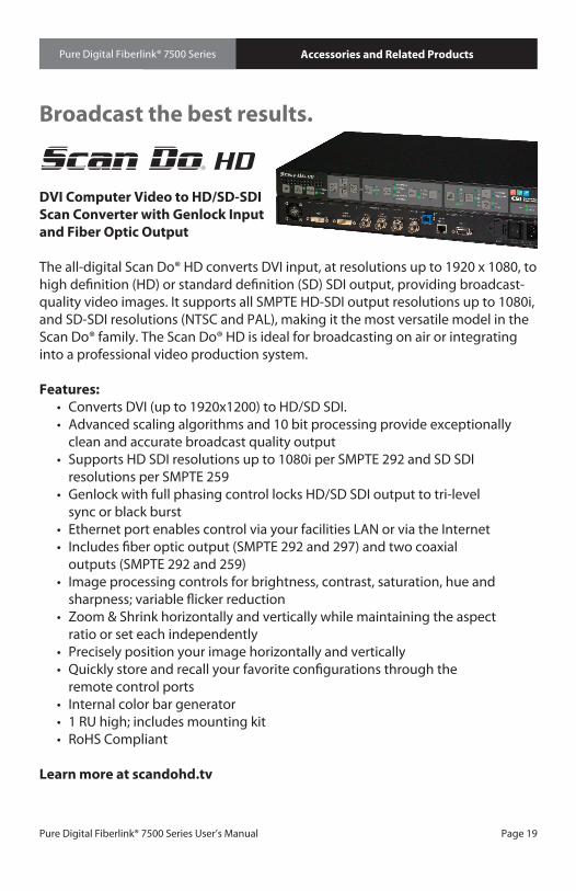
DVI Computer Video to HD/SD-SDI Scan Converter with Genlock Input and Fiber Optic Output
The all-digital Scan Do® HD converts DVI input, at resolutions up to 1920 x 1080, to high definition (HD) or standard definition (SD) SDI output, providing broadcast-quality video images. It supports all SMPTE HD-SDI output resolutions up to 1080i, and SD-SDI resolutions (NTSC and PAL), making it the most versatile model in the Scan Do® family. The Scan Do® HD is ideal for broadcasting on air or integrating into a professional video production system.
Features: • Converts DVI (up to 1920x1200) to HD/SD SDI. • Advanced scaling algorithms and 10 bit processing provide exceptionally clean and accurate broadcast quality output • Supports HD SDI resolutions up to 1080i per SMPTE 292 and SD SDI resolutions per SMPTE 259 • Genlock with full phasing control locks HD/SD SDI output to tri-level sync or black burst • Ethernet port enables control via your facilities LAN or via the Internet • Includes fiber optic output (SMPTE 292 and 297) and two coaxial outputs (SMPTE 292 and 259) • Image processing controls for brightness, contrast, saturation, hue and sharpness; variable flicker reduction • Zoom & Shrink horizontally and vertically while maintaining the aspect ratio or set each independently • Precisely position your image horizontally and vertically • Quickly store and recall your favorite configurations through the remote control ports • Internal color bar generator • 1 RU high; includes mounting kit • RoHS Compliant
Learn more at scandohd.tv
Accessories and Related Products
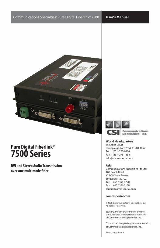
Pure Digital Fiberlink®7500 SeriesDVI and Stereo Audio Transmission over one multimode fiber.
World Headquarters55 Cabot CourtHauppauge, New York 11788 USATel: (631) 273-0404Fax: (631) [email protected]
AsiaCommunications Specialties Pte Ltd100 Beach Road#22-09 Shaw TowerSingapore 189702Tel: +65 6391 8790Fax: +65 6396 [email protected]
commspecial.com
©2008 Communications Specialties, Inc. All Rights Reserved.
Scan Do, Pure Digital Fiberlink and the starburst logo are registered trademarks of Communications Specialties, Inc.
CSI and the triangle designs are trademarks of Communications Specialties, Inc.
P/N 127315 Rev. A
Single Color (Black)
Single Color (Black)on Black Background
If you need to use the CSI logo on a non-solidbackground use the Photoshop Layered Files.©2005 Spectra Vision Productions, Inc.
Communications Specialties’ Pure Digital Fiberlink® 7500 User’s Manual