Embed Size (px)
Citation preview

1 California Motor Controls, Inc. Benicia, CA V2.0 Copyright 2005-2010 5/19/2010 www.cmcontrols.com Ph 707-746-6255
Lift Station Level Controller
Installation and Operation Manual
TMPUMP Vision

2 California Motor Controls, Inc. Benicia, CA V2.0 Copyright 2005-2010 5/19/2010 www.cmcontrols.com Ph 707-746-6255
1. Features
• Overview of Standard Features.......................................................... 5-6 • Access Security.................................................................................. 7 • Optional Features............................................................................... 7
2. Construction
• Communication .................................................................................. 8 • Remote Access .................................................................................. 8 • DataXport Software ............................................................................ 9 • Excel DDE Server Application............................................................ 9 • Web Server ........................................................................................ 10
3. Safety
• Safety ................................................................................................. 11 • Dimensions......................................................................................... 12 • Mounting............................................................................................. 13-14 • Wiring ................................................................................................. 15 • Communication Ports ......................................................................... 16-17 • Typical Wiring Diagram - Constant Speed or VFD Type .................... 18 • IO List ............................................................................................... 19
4. Sequence of Operation
A. Constant Speed Type - Manual or Automatic ...................................... 20 B. Variable Frequency Drive Type ........................................................... 21
• All Modes ................................................................................... 21 • PID Mode ................................................................................... 22-23 • Proportion Mode ........................................................................ 24 • Alternation.................................................................................. 25 • Alarm Conditions........................................................................ 26 • Pump Failure.............................................................................. 26 • Test Mode .................................................................................. 27 • Automatic Purge Control ............................................................ 27 • Manual Purge............................................................................. 27 • Transducer Scaling .................................................................... 28 • Data Logging.............................................................................. 28 • Trending..................................................................................... 28
Table of Contents
3 California Motor Controls, Inc. Benicia, CA V2.0 Copyright 2005-2010 5/19/2010 www.cmcontrols.com Ph 707-746-6255
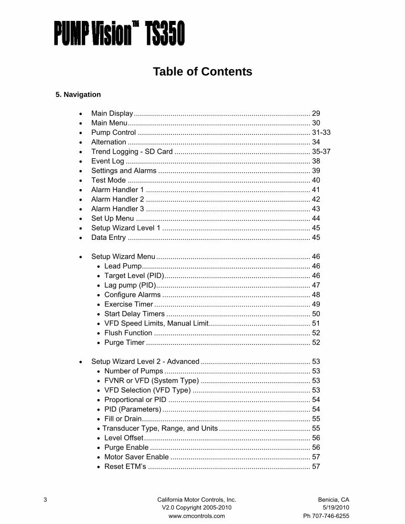
5. Navigation
• Main Display....................................................................................... 29 • Main Menu.......................................................................................... 30 • Pump Control ..................................................................................... 31-33 • Alternation .......................................................................................... 34 • Trend Logging - SD Card ................................................................... 35-37 • Event Log ........................................................................................... 38 • Settings and Alarms ........................................................................... 39 • Test Mode .......................................................................................... 40 • Alarm Handler 1 ................................................................................. 41 • Alarm Handler 2 ................................................................................. 42 • Alarm Handler 3 ................................................................................. 43 • Set Up Menu ...................................................................................... 44 • Setup Wizard Level 1 ......................................................................... 45 • Data Entry .......................................................................................... 45 • Setup Wizard Menu............................................................................ 46
• Lead Pump................................................................................... 46 • Target Level (PID)........................................................................ 46 • Lag pump (PID)............................................................................ 47 • Configure Alarms ......................................................................... 48 • Exercise Timer ............................................................................. 49 • Start Delay Timers ....................................................................... 50 • VFD Speed Limits, Manual Limit.................................................. 51 • Flush Function ............................................................................. 52 • Purge Timer ................................................................................. 52
• Setup Wizard Level 2 - Advanced ...................................................... 53 • Number of Pumps ........................................................................ 53 • FVNR or VFD (System Type) ...................................................... 53 • VFD Selection (VFD Type) .......................................................... 53 • Proportional or PID ...................................................................... 54 • PID (Parameters) ......................................................................... 54 • Fill or Drain................................................................................... 55 • Transducer Type, Range, and Units ............................................. 55 • Level Offset.................................................................................. 56 • Purge Enable ............................................................................... 56 • Motor Saver Enable ..................................................................... 57 • Reset ETM’s ................................................................................ 57
Table of Contents
4 California Motor Controls, Inc. Benicia, CA V2.0 Copyright 2005-2010 5/19/2010 www.cmcontrols.com Ph 707-746-6255
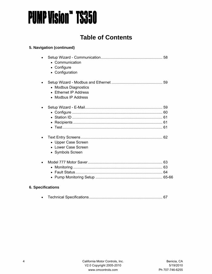
5. Navigation (continued)
• Setup Wizard - Communication.......................................................... 58 • Communication • Configure • Configuration
• Setup Wizard - Modbus and Ethernet ................................................ 59
• Modbus Diagnostics • Ethernet IP Address • Modbus IP Address
• Setup Wizard - E-Mail......................................................................... 59
• Configure ..................................................................................... 60 • Station ID ..................................................................................... 61 • Recipients .................................................................................... 61 • Test .............................................................................................. 61
• Text Entry Screens............................................................................. 62
• Upper Case Screen • Lower Case Screen • Symbols Screen
• Model 777 Motor Saver ...................................................................... 63
• Monitoring .................................................................................... 63 • Fault Status.................................................................................. 64 • Pump Monitoring Setup ............................................................... 65-66
6. Specifications
• Technical Specifications..................................................................... 67
Table of Contents

5 California Motor Controls, Inc. Benicia, CA V2.0 Copyright 2005-2010 5/19/2010 www.cmcontrols.com Ph 707-746-6255
The PUMP Vision TS350 Level Controller is a microprocessor based level controller de-signed with an easy to use color touch screen type operator interface.
The PUMP Vision TS350 level controller can be configured to operate in simplex, duplex, triplex and quadruplex mode as standard. It can be set to control the pumps in constant speed mode, as well as variable speed mode when variable frequency drives (VFDs) are used.
A trending screen is provided to allow the operator to track recent changes in the sump level. In VFD mode a graph of the VFD speed is also shown. Data logging is provided to keep a record of fault conditions.
Overview of Standard Features
The PUMP Vision TS provides the following functions in a level control application:
• Constant speed mode • Variable speed mode
Proportion PID Mode
• Setpoint control of an analog input with these set points: Stop lead pump Start lead pump Stop lag pump (for each lag pump independently) Start lag pump (for each lag pump independently) High level alarm Low level alarm • Display of liquid level in 1/10 ft resolution • Display of pump call status • Display of pump status for each pump Off, Running, Called, Failed, Out-of-service “Soft” H-O-A - used for remotely controlling the pump Elapsed run time Number of starts counter In VFD mode: VFD command speed VFD output frequency Output watts Manual speed control • Alternation mode selector Automatic — alternates with each pumping cycle Time clock — alternates daily Manual — any pump can be set as the lead pump
Features
6 California Motor Controls, Inc. Benicia, CA V2.0 Copyright 2005-2010 5/19/2010 www.cmcontrols.com Ph 707-746-6255
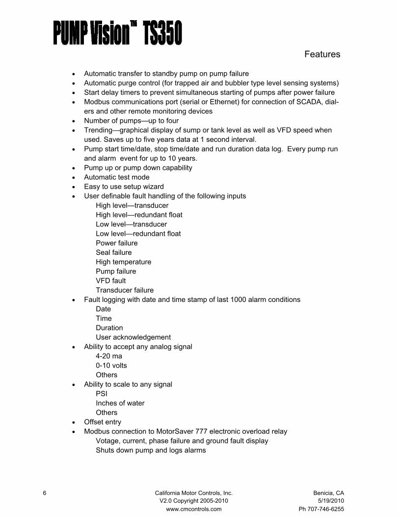
• Automatic transfer to standby pump on pump failure • Automatic purge control (for trapped air and bubbler type level sensing systems) • Start delay timers to prevent simultaneous starting of pumps after power failure • Modbus communications port (serial or Ethernet) for connection of SCADA, dial-
ers and other remote monitoring devices • Number of pumps—up to four • Trending—graphical display of sump or tank level as well as VFD speed when
used. Saves up to five years data at 1 second interval. • Pump start time/date, stop time/date and run duration data log. Every pump run
and alarm event for up to 10 years. • Pump up or pump down capability • Automatic test mode • Easy to use setup wizard • User definable fault handling of the following inputs High level—transducer High level—redundant float Low level—transducer Low level—redundant float Power failure Seal failure High temperature Pump failure VFD fault Transducer failure • Fault logging with date and time stamp of last 1000 alarm conditions
Date Time Duration User acknowledgement
• Ability to accept any analog signal 4-20 ma 0-10 volts Others • Ability to scale to any signal PSI Inches of water Others • Offset entry • Modbus connection to MotorSaver 777 electronic overload relay Votage, current, phase failure and ground fault display Shuts down pump and logs alarms
Features
7 California Motor Controls, Inc. Benicia, CA V2.0 Copyright 2005-2010 5/19/2010 www.cmcontrols.com Ph 707-746-6255
Access Security
There are three levels of access to the menus, designed to allow any user access to the nor-mal operation modes and qualified personnel to have access to the setpoints. The final level of access is reserved for the higher level setup of the system.
• No password protection Level display, Pump Control, Alternation, Time, Trending, Alarms
• 1st level password protection All set points—Stop, start, alarms, timers, alarm handling and purge cycle
• 2nd level password protection System setup—number of pumps, VFD or constant speed, PID, transducer, ETM reset, start counter reset, network configuration, email configuration
Optional features
The PUMP Vision can be ordered with a second communication port, either Ethernet or se-rial. With a wide variety of methods, this port can be connected to a LAN or WLAN. With such a connection, the following integral features can be accessed: Email alarm notification—up to four recipients Text message alarm notification—up to four recipients Web Server Operate the pumps Change set points Monitor level Monitor alarm conditions DDE Server Operate the pumps Change set points Monitor level Monitor alarm conditions Remote Access Program Provides a virtual PUMP Vision on a PC—completely control the TS350 Access to the data log SD Card Manager Remotely download the data in the SD data memory to view trend chart Remotely download the event log to read pump run and alarm data
Features
8 California Motor Controls, Inc. Benicia, CA V2.0 Copyright 2005-2010 5/19/2010 www.cmcontrols.com Ph 707-746-6255
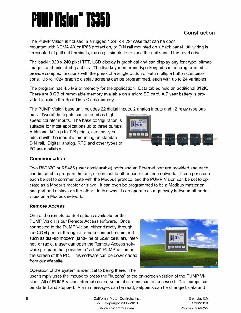
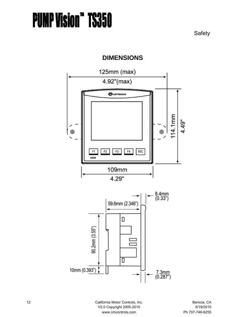
The PUMP Vision is housed in a rugged 4.29” x 4.29” case that can be door mounted with NEMA 4X or IP65 protection, or DIN rail mounted on a back panel. All wiring is terminated at pull out terminals, making it simple to replace the unit should the need arise.
The backlit 320 x 240 pixel TFT, LCD display is graphical and can display any font type, bitmap images, and animated graphics. The five key membrane type keypad can be programmed to provide complex functions with the press of a single button or with multiple button combina-tions. Up to 1024 graphic display screens can be programmed, each with up to 24 variables.
The program has 4.5 MB of memory for the application. Data tables hold an additional 312K. There are 8 GB of removable memory available on a micro SD card. A 7 year battery is pro-vided to retain the Real Time Clock memory.
The PUMP Vision base unit includes 22 digital inputs, 2 analog inputs and 12 relay type out-puts. Two of the inputs can be used as high-speed counter inputs. The base configuration is suitable for most applications up to three pumps. Additional I/O, up to 128 points, can easily be added with the modules mounting on standard DIN rail. Digital, analog, RTD and other types of I/O are available.
Communication
Two RS232C or RS485 (user configurable) ports and an Ethernet port are provided and each can be used to program the unit, or connect to other controllers in a network. These ports can each be set to communicate with the Modbus protocol and the PUMP Vision can be set to op-erate as a Modbus master or slave. It can even be programmed to be a Modbus master on one port and a slave on the other. In this way, it can operate as a gateway between other de-vices on a Modbus network.
Remote Access
One of the remote control options available for the PUMP Vision is our Remote Access software. Once connected to the PUMP Vision, either directly through the COM port, or through a remote connection method such as dial-up modem (land-line or GSM cellular), Inter-net, or radio, a user can open the Remote Access soft-ware program that provides a “virtual” PUMP Vision on the screen of the PC. This software can be downloaded from our Website
Operation of the system is identical to being there. The user simply uses the mouse to press the “buttons” of the on-screen version of the PUMP Vi-sion. All of PUMP Vision information and setpoint screens can be accessed. The pumps can be started and stopped. Alarm messages can be read, setpoints can be changed, data and
Construction

9 California Motor Controls, Inc. Benicia, CA V2.0 Copyright 2005-2010 5/19/2010 www.cmcontrols.com Ph 707-746-6255
DataXport
DataXport is a powerful software package that can ei-ther automatically, on a scheduled time, or manually extract data from the PUMP Vision’s data logging mem-ory and insert it into an Excel spreadsheet. Once con-nected to the PUMP Vision, either directly through the COM port, or through a remote connection method, such as dial-up modem (land-line or GSM cellular), Internet, or radio, the user can receive the data directly into their spreadsheet.
Important data, such as liquid levels, pump run times, and alarm conditions, all with date and time stamps, can be stored and analyzed.
Excel DDE
Our Excel DDE server application is antoher method of obtaining data from the PUMP Vision. With this application, the user can connect to the PUMP Vision by one of the previously described methods, and operate the PUMP Vision with either our own Excel based “dashboard”, or one that they create with their own design.
The example shown here, which is available from California Motor Controls, has “HAND-OFF-AUTO” buttons to remotely start and stop the pumps, status display of the pumps, alarms and alterna-tion, setpoint access for the user to change the setpoints, and date and time stamps of the last alarms
The DDE application program and data file that we provide makes it simple to setup a custom spreadsheet. Multiple lift stations can be setup with a separate station on each sheet of a mul-tiple sheet file.
Construction

10 California Motor Controls, Inc. Benicia, CA V2.0 Copyright 2005-2010 5/19/2010 www.cmcontrols.com Ph 707-746-6255
Web Server
The PUMP Vision has a built in Web Server. When connected to the Internet through the Ethernet port option, the system can be monitored and operated using an Internet browser from any remote location. Simply open your browser to the IP address of the PUMP Vision and the web pages will appear.
Pump operating status can be viewed, the pump HAND-OFF-AUTO mode can be changed, and start and stop set points can be changed.
Construction

11 California Motor Controls, Inc. Benicia, CA V2.0 Copyright 2005-2010 5/19/2010 www.cmcontrols.com Ph 707-746-6255
SAFETY CONSIDERATIONS
• Failure to comply with appropriate safety guidelines can result is severe personal injury or property damage. Always exercise proper caution when working with electrical equipment.
• Do not attempt to use the controller with voltage exceeding permissible levels. Permissible voltage levels are listed in the technical specifica-tions provided in this manual.
• Install an external circuit breaker or fuse and take all appropriate safety measures against short-circuiting in external wiring.
• Do not install in areas with: excessive or conductive dust, corrosive or flammable gas, moisture or rain, excessive heat, regular impact shocks or excessive vibration.
• Do not place in water or let water leak onto the controller.
• Do not allow debris to fall inside the unit during installation.
• Double-check all the wiring before turning on the power supply.
• Ascertain that terminal blocks are properly secured in place.
• Do not touch live wires.
• Stay as far as possible for high-voltage cables and power equipment..
• Leave a minimum of 10mm space for ventilation between the top and bottom edges of the controller and the enclosure walls.
• A non-isolated power supply can be used provided that a 0V signal is connected to the chassis.
• Standard safety considerations require that metal cabinet panels be grounded to avoid electrocution.
• Do not connect either the Neutral or Line signal of the 120VAC circuit to the device’s 0V terminal.
• In the event of voltage fluctuations, or non-conformity to voltage power supply specifications, connect the device to a regulated power supply.
• The wiring of this device is specifically designed to be safe any easy. A technician or engineer trained in the local and National Electric Code should perform all tasks associated with the electrical wiring of the de-vice.
Safety
12 California Motor Controls, Inc. Benicia, CA V2.0 Copyright 2005-2010 5/19/2010 www.cmcontrols.com Ph 707-746-6255
DIMENSIONS
Safety
13 California Motor Controls, Inc. Benicia, CA V2.0 Copyright 2005-2010 5/19/2010 www.cmcontrols.com Ph 707-746-6255
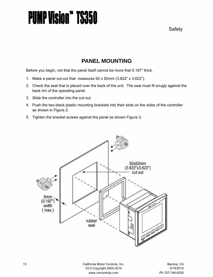
PANEL MOUNTING
Before you begin, not that the panel itself cannot be more that 0.197” thick.
1. Make a panel cut-out that measures 92 x 92mm (3.622” x 3.622”).
2. Check the seal that is placed over the back of the unit. The seal must fit snugly against the back rim of the operating panel.
3. Slide the controller into the cut-out.
4. Push the two black plastic mounting brackets into their slots on the sides of the controller as shown in Figure 2.
5. Tighten the bracket screws against the panel as shown Figure 3.
Safety
14 California Motor Controls, Inc. Benicia, CA V2.0 Copyright 2005-2010 5/19/2010 www.cmcontrols.com Ph 707-746-6255
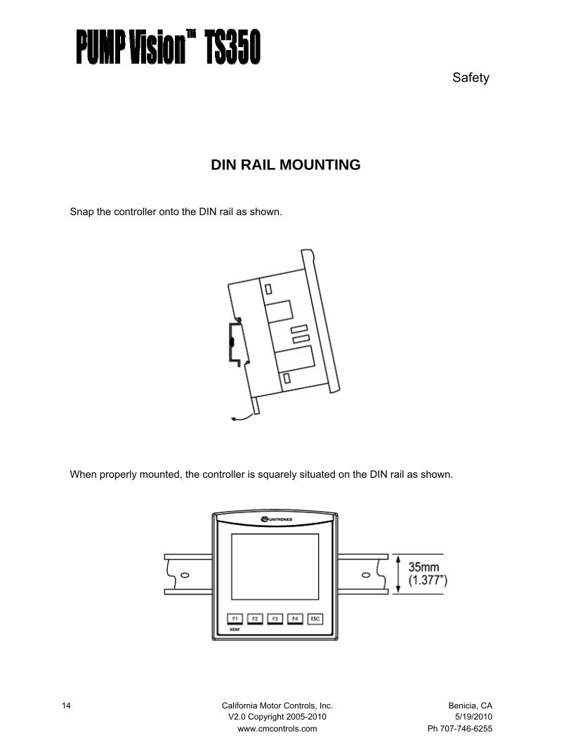
DIN RAIL MOUNTING
Snap the controller onto the DIN rail as shown.
When properly mounted, the controller is squarely situated on the DIN rail as shown.
Safety
15 California Motor Controls, Inc. Benicia, CA V2.0 Copyright 2005-2010 5/19/2010 www.cmcontrols.com Ph 707-746-6255
WIRING
.
On-board I/O
I/O connection points are provided by external connectors at the top and bottom of the control-ler. The connectors plug in, enabling quick and easy removal. They provide screw-type con-nection points for the power source, inputs an outputs. The connection points are clearly la-beled on the controller itself.
The top generally provides connections for the power supply, analog inputs and digital inputs. The bottom connector provides terminals for the relay outputs.
Connections to the Controller
1. Strip the wire to a length of 0.250-0.300 inches.
2. Unscrew the terminal to its widest position before inserting a wire.
3. Insert the wire completely into the terminal to ensure a proper connection.
4. Tighten enough to keep the wire from pulling free.
5. Use 14 gauge to 26 gauge wire.
6. Do not exceed 1 inch pounds of torque.
7. We recommend crimp connectors (ferrules) in the wire ends.
Wiring Considerations • A technician or engineer trained in the local and National Electric Code should
perform all tasks associated with the electrical wiring of the controller.
• Input or output cables should not be run though the same multicore cable or share the same wire.
• Do not lay input or output cables near high voltage power cables.
• Allow for voltage drop and noise interference with input and output lines used over an extended distance. Use wire that is properly sized for the current load.
• Double-check all the wiring before turning on the power supply.
• Unused I/O terminals should not be connected. Ignoring this directive may damage the controller.
Safety

16 California Motor Controls, Inc. Benicia, CA V2.0 Copyright 2005-2010 5/19/2010 www.cmcontrols.com Ph 707-746-6255
COMMUNICATION PORTS
The PUMP Vision has two serial ports. Both can be set for RS232 or RS485 independently.
The PUMP Vision is connected directly to the PC with a standard RJ11 type cable which should not be longer than 10’ when using RS232. An RJ11 to 9 pin D connector is used to connect to the PC.
Safety

17 California Motor Controls, Inc. Benicia, CA V2.0 Copyright 2005-2010 5/19/2010 www.cmcontrols.com Ph 707-746-6255
RS485 Use RS485 to create multi-drop network containing up to 32 stations, or for Modbus communi-cations.
Note that when a port is set to RS485, both RS232 and RS485 can be used simultaneously if flow control signals DTR and DSR are not used.
• Note that the ports are not isolated. If the controller is used with a non-isolated external device, avoid potential voltage that exceeds ±10V.
• To avoid damaging the system, all non-isolated device ports should relate to the same ground signal.
• Use shielded, twisted pair cable.
• Minimize the drop length leading form each device to the bus.
• Ideally, the main cable should be run in and out of the network device.
• Do not cross positive (A) and negative (B) signals. Positive terminals must be
Safety

18 California Motor Controls, Inc. Benicia, CA V2.0 Copyright 2005-2010 5/19/2010 www.cmcontrols.com Ph 707-746-6255
Typical Wiring Diagram for Constant Speed or VFD Mode Safety

19 California Motor Controls, Inc. Benicia, CA V2.0 Copyright 2005-2010 5/19/2010 www.cmcontrols.com Ph 707-746-6255
Connect input and output devices as needed.
Inputs I0 Pump 1 HOA - AUTO I1 Pump 2 HOA - AUTO I2 Pump 3 HOA - AUTO I3 Pump 4 HOA - AUTO I4 Pump 1 starter auxiliary contact I5 Pump 2 starter auxiliary contact I6 Pump 3 starter auxiliary contact I7 Pump 4 starter auxiliary contact I8 Pump 1 high motor temperature I9 Pump 2 high motor temperature I10 Pump 3 high motor temperature I11 Pump 4 high motor temperature I12 Power failure I16 Pump 1 seal failure I17 Pump 2 seal failure I18 Pump 3 seal failure I19 Pump 4 seal failure I20 High level alarm - redundant float switch I21 Low level alarm - redundant float switch AN0 0-10V transducer input AN1 4-20ma transducer input Outputs O0 Pump 1 run O1 Pump 2 run O2 Pump 3 run O3 Pump 4 run O4 Pump 1 Out-of-Service indicator O5 Pump 2 Out-of-Service indicator O6 Pump 3 Out-of-Service indicator O7 Pump 4 Out-of-Service indicator O8 Alarm light O9 Alarm horn O10 Alarm contact
IO LIST Safety

20 California Motor Controls, Inc. Benicia, CA V2.0 Copyright 2005-2010 5/19/2010 www.cmcontrols.com Ph 707-746-6255
Constant Speed Operation
It is recommended that the control system include an H-O-A selector switch. Inputs are pro-vided and programmed into the PUMP Vision for a contact of the AUTO position of the selector switch. When the H-O-A is place into the HAND position, the PUMP Vision will be bypassed and the pump should run.
If the contact to the HOA-Auto input of the PUMP Vision is not closed, the PUMP Vision sets the status of that pump to Out-Of-Service. When the H-O-A is placed into the AUTO position, the pump is available to run as instructed by the PUMP Vision.
A. Constant Speed Manual Operation
Touching the HAND, OFF or AUTO buttons on the Pump Status page will select the mode of operation.
Touching the HAND button will start the pump in manual mode.
This “soft” H-O-A is provided in the PUMP Vision to enable remote operation of the pumps, either through the Remote Access system, DDE program, through the Web Server system, or by other SCADA systems.
A1. Constant Speed Automatic Operation
The pumps are available for automatic run when the AUTO selector switch input is enabled and the “soft” H-O-A is in the AUTO mode.
The analog level signal is converted to tenths of feet and that value is compared to the start and stop set points that are entered into the system by the user.
On rising level, when the level is equal to or greater than the lead pump start set point, the lead pump will start. If the level continues to rise beyond the start lag pump set point, the lag pump will start. If there are more than two pumps, rising level will start the additional pumps in se-quence.
On falling level, the pumps will sequence off as the level drops below the respective stop set points.
The start and stop sequence is reverse when the controller is configured for pump up (fill).
Sequence of Operation Constant Speed

21 California Motor Controls, Inc. Benicia, CA V2.0 Copyright 2005-2010 5/19/2010 www.cmcontrols.com Ph 707-746-6255
B. Variable Frequency Drive Manual Operation
When the hard wired H-O-A is place into the HAND position, the PUMP Vision will be by-passed and the pump will run at a user preset speed. The preset speed is entered on the Pump Status screen and saved into the VFD. The VFD is not dependant upon the PUMP Vi-sion in any way for manual operation.
When the hard wired H-O-A is place into the AUTO position, the mode of operation is selected by touching the HAND, OFF or AUTO buttons on the Pump Status screen.
When the “soft” HOA is set to HAND, the pump will run and the VFD speed can be increased or decreased using the INC or DEC buttons on the Pump Control screen.
This “soft” H-O-A is provided in the PUMP Vision to enable remote operation of the pumps, either through the Remote Access system, DDE program, through the Web Server system, or by other SCADA systems.
Sequence of Operation Variable Speed
All Modes
22 California Motor Controls, Inc. Benicia, CA V2.0 Copyright 2005-2010 5/19/2010 www.cmcontrols.com Ph 707-746-6255
Variable Frequency Drive Automatic Operation—PID Mode
The pumps are available for automatic run when the AUTO selector switch input is enabled and the “soft” H-O-A is in the AUTO mode.
The analog level signal is converted to tenths of feet and that value is compared to the start and stop set points that are entered into the system by the user.
On rising level, when the level is equal to or greater than the lead pump start set point, the lead pump will start and will maintain the level at the “Target” set point
On falling level, the pumps will sequence off as the level drops below the respective stop set points.
The start and stop sequence is reverse when the controller is configured for pump up (fill).
Sequence of Operation Variable Speed
PID Mode
Variable Frequency Drive Speed Control—PID Mode
Once started, the lead pump VFD will immediately ramp up to the minimum run set point at the rate programmed into the VFD acceleration function. The speed of the drive will be modulated automatically by the PLC to maintain the target level set point. When the drive reaches minimum speed, the sample cycle timer begins timing. When the sample cycle timer elapses, a change will be made to the VFD speed proportional to the sys-tem level deviation from the target level set point.
The speed can increase up to the maximum speed set point and decrease to the minimum speed set point. The speed changes occur at the interval set in the sample timer.
The proportion of the change can be adjusted in the PID setup screen and is entered as a ratio of ft.:% Speed. If a 1.0:1 ratio is set, the VFD speed will change 1% for each 0.1 feet of devia-tion.
The amount of change is limited by the trim set point. This function is useful in controlling a “runaway” speed condition. A typical setting for the trim may be 6.0% which would allow the VFD speed to change by that amount with each sample timer cycle.

23 California Motor Controls, Inc. Benicia, CA V2.0 Copyright 2005-2010 5/19/2010 www.cmcontrols.com Ph 707-746-6255
Variable Frequency Drive Lag Pump Start—PID Mode
When the speed of the VFD(s) running meets or exceeds the lag pump start set point, the lag pump start delay timer begins timing.
When the timer elapses, the lag pump will start and ramp up to match the speed of the lead pump at the rate programmed into the VFD acceleration function.
While running, the lead pump and lag pump will modulate at the same speed.
In triplex or quadraplex systems, each lag pump starts in the same manner.
Variable Frequency Drive Lag Pump Stop—PID Mode
When the speed of the VFD(s) running is at or below the lag pump stop set point, the last lag pump that started will stop.
In triplex or quadraplex systems, each lag pump stops in the same manner, with a 60 second delay between stops.
Sequence of Operation Variable Speed
PID Mode
24 California Motor Controls, Inc. Benicia, CA V2.0 Copyright 2005-2010 5/19/2010 www.cmcontrols.com Ph 707-746-6255
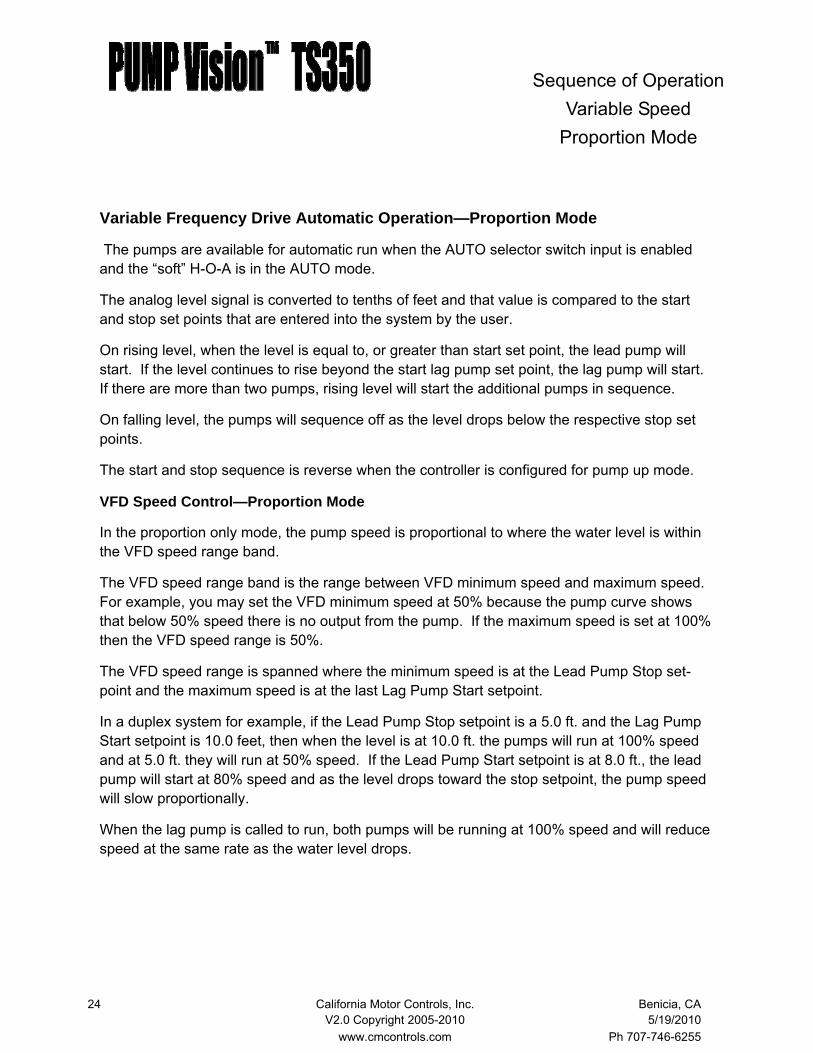
Variable Frequency Drive Automatic Operation—Proportion Mode
The pumps are available for automatic run when the AUTO selector switch input is enabled and the “soft” H-O-A is in the AUTO mode.
The analog level signal is converted to tenths of feet and that value is compared to the start and stop set points that are entered into the system by the user.
On rising level, when the level is equal to, or greater than start set point, the lead pump will start. If the level continues to rise beyond the start lag pump set point, the lag pump will start. If there are more than two pumps, rising level will start the additional pumps in sequence.
On falling level, the pumps will sequence off as the level drops below the respective stop set points.
The start and stop sequence is reverse when the controller is configured for pump up mode.
VFD Speed Control—Proportion Mode
In the proportion only mode, the pump speed is proportional to where the water level is within the VFD speed range band.
The VFD speed range band is the range between VFD minimum speed and maximum speed. For example, you may set the VFD minimum speed at 50% because the pump curve shows that below 50% speed there is no output from the pump. If the maximum speed is set at 100% then the VFD speed range is 50%.
The VFD speed range is spanned where the minimum speed is at the Lead Pump Stop set-point and the maximum speed is at the last Lag Pump Start setpoint.
In a duplex system for example, if the Lead Pump Stop setpoint is a 5.0 ft. and the Lag Pump Start setpoint is 10.0 feet, then when the level is at 10.0 ft. the pumps will run at 100% speed and at 5.0 ft. they will run at 50% speed. If the Lead Pump Start setpoint is at 8.0 ft., the lead pump will start at 80% speed and as the level drops toward the stop setpoint, the pump speed will slow proportionally.
When the lag pump is called to run, both pumps will be running at 100% speed and will reduce speed at the same rate as the water level drops.
Sequence of Operation Variable Speed
Proportion Mode

25 California Motor Controls, Inc. Benicia, CA V2.0 Copyright 2005-2010 5/19/2010 www.cmcontrols.com Ph 707-746-6255
Alternation of the Pumps (Constant and Variable Speed)
The pump alternation mode is set by the user. Automatic, time clock and manual modes are available.
• Automatic mode—the pumps will alternate after each pumping cycle. • Time clock—the pumps will alternate daily at the time set by the user. • Manual—the pumps will not alternate. The lead pump is selected by the user
Sequence of Operation

26 California Motor Controls, Inc. Benicia, CA V2.0 Copyright 2005-2010 5/19/2010 www.cmcontrols.com Ph 707-746-6255
Alarm Conditions
All alarm conditions with operate according to the way they are setup in the Setup Wizard. Each alarm can optionally be setup to:
• Be enabled or disabled • Stop the pumps • Require manual reset • Sound the horn • Light the alarm light • Flash the alarm light • Close the alarm contact • Send an email • User adjustable time delay
All enable alarm conditions will be logged into the alarm data logger.
All enable alarm conditions will be managed by the fault handler.
For all alarm conditions, touching the screen of the PUMP Vision will silence the horn output.
Inputs are provided for the following alarm conditions:
• High level—transducer • Low level—transducer • High level—redundant float • Low level—redundant float • High motor temperature for each pump • Seal failure for each pump • Pump failure for each pump • Power failure In VFD mode the VFD Fault conditions are monitored through Modbus and annunciated on the controller. Pump Failure
This condition is determined by the motor starter failing to close an input to the controller within a preset time period. If a pump fails to start, the pumping duty is automatically transfer to the next available pump in sequence.
The pump can be taken “Out-of-service” and this failure alarm is prevented, by putting either the “soft” H-O-A, or the panel H-O-A into the OFF position. This allows maintenance of the pump without generating an alarm condition. As with a pump failure condition, the pumping duty is automatically transferred to the remaining pump(s).
Sequence of Operation
27 California Motor Controls, Inc. Benicia, CA V2.0 Copyright 2005-2010 5/19/2010 www.cmcontrols.com Ph 707-746-6255
Test Mode
The PUMP Vision has a test mode which simulates the rise and fall of the level and enables the complete testing or the system without filling and re-filling the tank. Once activated, the level is simulated within controller, starting a 0.0 ft and rising to the top of the level scale at the rate of 1.0 ft in 5 seconds. As it rises, pump run outputs and alarm outputs will activate at the programmed set points. When the level reaches the top of the range, it will automatically re-verse and fall back down to 0.0 ft. The outputs will drop out at their programmed set points.
While the test mode function will automatically rise and fall through the full level range, the di-rection of the simulation can be manually reversed by touching the up or down buttons.
The user can touch the STOP button key to leave the test mode at any time and the system will return to the normal run mode. The system will automatically exit the test mode after five minutes. This feature insures that the user will not inadvertently leave the system in test mode.
Automatic Purge Control
An output is provided on the PUMP Vision to control a purge compressor and solenoid valve. This function is necessary for reactive air and bubbler type level sensing systems.
The frequency of purge cycle, and the duration of the purge is defined by user set points in the Purge setup page of the PUMP Vision.
When the purge cycle runs, the PUMP Vision will “freeze” the level signal from the level trans-ducer for two seconds before the purge starts until 15 seconds after the compressor stops. This prevents the higher pressure condition that the purge process creates from interfering with the pumps starting and stopping, or causing a false high level alarm.
Manual Purge
The system can be manually purged by pressing the MAN key while in the purge setup page of the PUMP Vision. The purge duration will be the same as with the automatic purge mode.
Sequence of Operation
28 California Motor Controls, Inc. Benicia, CA V2.0 Copyright 2005-2010 5/19/2010 www.cmcontrols.com Ph 707-746-6255
Transducer Scaling
The PUMP Vision is designed to allow nearly any type of level sensing device to be connected, including voltage or current types with any range.
To scale the range of the PUMP Vision to match the transducer, go to the Advance Setup Wiz-ard. The scale is entered with four parameters.
First, the transducer type is entered. Either 0-10V or 4-20ma. Note that the transducer must be physically wired to the appropriate input. See the wiring diagram.
Next, the range of the measurement is entered (example: 0—15 PSI, or 0-120 ft. water).
Then the type of unit is entered as either PSI or Inches of Water.
Finally, an offset can be programmed. The offset adds a value to the level display. This is useful when the transducer or bubbler tube is positioned off of the tank floor, preventing the buildup of debris from interfering with the measurement. The resulting display will be an actual liquid depth.
Fault Data Logging
Fault conditions are logged into memory with a date and time stamp. When a fault condition occurs, the fault status indicator will light on the main screen. Touching the fault status indica-tor will take the user to the fault handler when details about the alarm condition can be viewed and managed.
The ALARM button in the main menu will take the user to the fault data logger where the last three fault conditions are displayed with the date and time of occurrence. The screen can be scrolled down through the past 1000 fault conditions.
When the screen is exited and then re-entered, the log automatically returns to showing the latest three fault conditions.
Trending
The on screen trending graph plots the sump or tank level with a reading saved every second. It saves history for the past 1.5 hours. The graph can be scrolled by the user to view the his-tory. The optional micro SD card records the trend data in a file that is automatically created once a month. A maximum of 64 months is retained on the SD card.
Sequence of Operation

29 California Motor Controls, Inc. Benicia, CA V2.0 Copyright 2005-2010 5/19/2010 www.cmcontrols.com Ph 707-746-6255
NAVIGATING CONTROLLER
The PUMP Vision V350 is an easy to use touch screen controller with a menu driven display. Each display includes intuitive buttons to navigate through the controller.
Navigation
System Time
Fault Status
Sump or Tank Level
Menu Access
Sump or Tank Level - Displays the level of the sump or tank, both graphically and digitally in tenths of a foot.
System Time - The system time is used to provide a data and time stamp to the fault logger and also to set the time of day that the system alternates if time clock alternation mode is selected.
Menu Access - Touch this button to navigate to the Main Menu screen.
Alarm Silence - If an alarm horn is connected to the controller, touch the screen anywhere to si-lence the horn.
Fault Status - Displays system normal or fault condition. Touch this button to access fault mes-sage handler.
Fault Message - Displays active alarm conditions. Touch this text to scroll through all active fault conditions.
MAIN DISPLAY SCREEN
Fault Message

30 California Motor Controls, Inc. Benicia, CA V2.0 Copyright 2005-2010 5/19/2010 www.cmcontrols.com Ph 707-746-6255
Navigation
Alternation - Touch to go to alternation status and setup screen
Trending - Touch to go to trending screen
Alarms - Touch to go to fault logger screen
Alarm Reset - Touch to go to reset any alarm condition that requires manual reset
Settings - Touch to go to setting information screen
Setup Wizard - Touch to go to start the system setup wizard
Test Mode - Touch to go to automatic test mode screen
*Purge - Touch to go to purge timer setup screen. *Only available if purge function is en-abled in the setup wizard.
Back - Touch to go back to the main screen. Pressing the ESC will return to the main screen from any location.
Pump Control
Controls buttons are provided for up to four pumps, depending on how the system is configured in the system setup wizard.
Touching the screen button or pressing the F function keys are the two methods of changing the screen to Pump Control screen.
MAIN MENU SCREEN

31 California Motor Controls, Inc. Benicia, CA V2.0 Copyright 2005-2010 5/19/2010 www.cmcontrols.com Ph 707-746-6255
Navigation
Multilingual—The PUMP Vision is user configurable for English or Spanish. By simply touching the language button on the main menu screen, the text for the entire system is changed from English to Spanish, or from Spanish to English. This makes it possible for us-ers to operate the controller in the language they are most comfortable with.
It is planned that more languages will be added as requested.
Touch the language button and all of the screens change to display the text in that language.
MAIN MENU SCREEN
English Spanish
32 California Motor Controls, Inc. Benicia, CA V2.0 Copyright 2005-2010 5/19/2010 www.cmcontrols.com Ph 707-746-6255
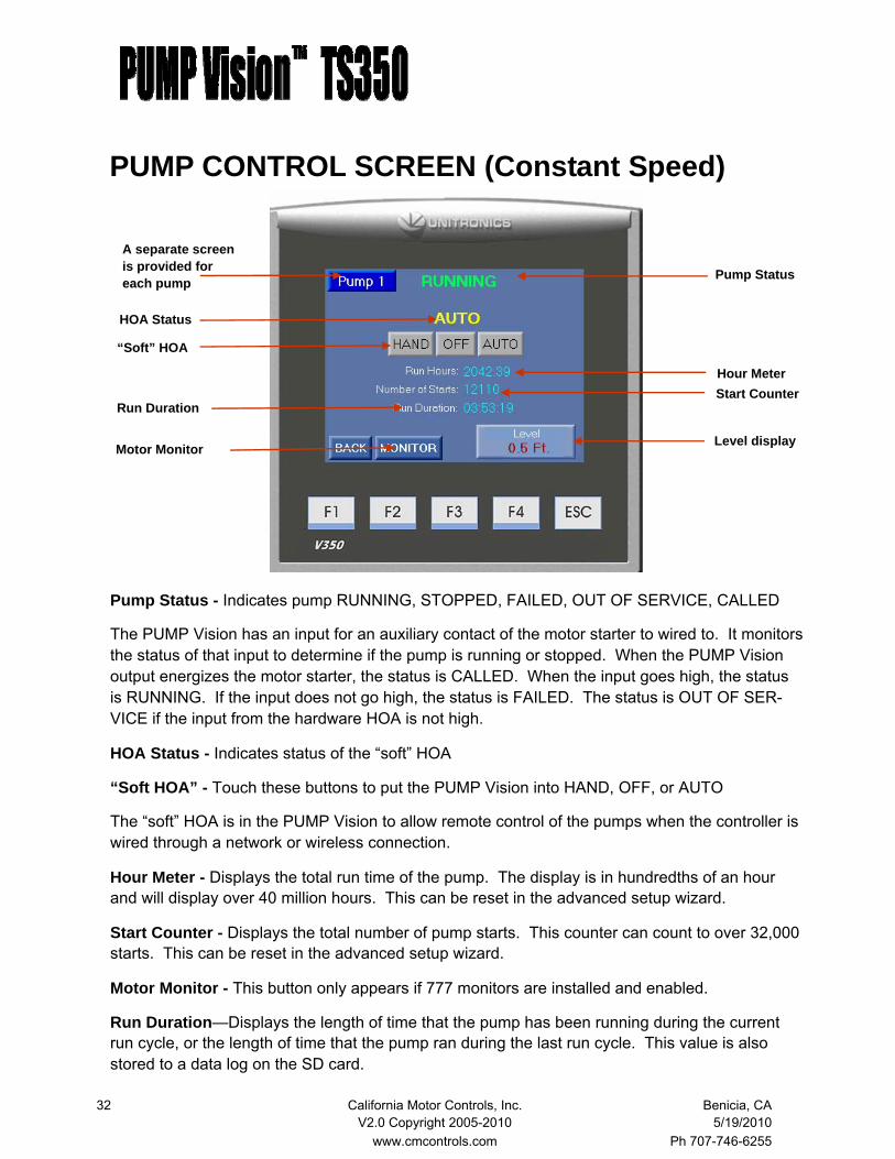
PUMP CONTROL SCREEN (Constant Speed)
Pump Status - Indicates pump RUNNING, STOPPED, FAILED, OUT OF SERVICE, CALLED
The PUMP Vision has an input for an auxiliary contact of the motor starter to wired to. It monitors the status of that input to determine if the pump is running or stopped. When the PUMP Vision output energizes the motor starter, the status is CALLED. When the input goes high, the status is RUNNING. If the input does not go high, the status is FAILED. The status is OUT OF SER-VICE if the input from the hardware HOA is not high.
HOA Status - Indicates status of the “soft” HOA
“Soft HOA” - Touch these buttons to put the PUMP Vision into HAND, OFF, or AUTO
The “soft” HOA is in the PUMP Vision to allow remote control of the pumps when the controller is wired through a network or wireless connection.
Hour Meter - Displays the total run time of the pump. The display is in hundredths of an hour and will display over 40 million hours. This can be reset in the advanced setup wizard.
Start Counter - Displays the total number of pump starts. This counter can count to over 32,000 starts. This can be reset in the advanced setup wizard.
Motor Monitor - This button only appears if 777 monitors are installed and enabled.
Run Duration—Displays the length of time that the pump has been running during the current run cycle, or the length of time that the pump ran during the last run cycle. This value is also stored to a data log on the SD card.
HOA Status
“Soft” HOA
Hour Meter Start Counter
A separate screen is provided for each pump
Level display
Run Duration
Pump Status
Motor Monitor

33 California Motor Controls, Inc. Benicia, CA V2.0 Copyright 2005-2010 5/19/2010 www.cmcontrols.com Ph 707-746-6255
PUMP CONTROL SCREEN (VFD Mode)
Pump Status - Indicates pump RUNNING, STOPPED, FAILED, OUT OF SERVICE, CALLED
The PUMP Vision has an input for an auxiliary contact of the motor starter to connected to. It monitors the status of that input to determine if the pump is running or stopped. When the PUMP Vision output energizes the motor starter, the status is CALLED. When the input goes high, the status is RUNNING. If the input does not go high, the status is FAILED. The status is OUT OF SERVICE if the input from the hardware HOA is not high.
HOA Status - Indicates status of the “soft” HOA
“Soft HOA” - Touch these buttons to put the PUMP Vision into HAND, OFF, or AUTO
The “soft” HOA is in the PUMP Vision to allow remote control of the pumps when the controller is wired through a network or wireless connection.
Hour Meter - Displays the total run time of the pump. The display is in hundredths of an hour and will display over 40 million hours. This can be reset in the advanced setup wizard.
Start Counter - Displays the total number of pump starts. This counter can count to over 32,000 starts. This can be reset in the advanced setup wizard.
Run Duration—Displays the length of time that the pump has been running during the current run cycle, or the length of time that the pump ran during the last run cycle. This value is also stored to a data log on the SD card.
A separate screen is provided for each pump
“Soft” HOA HOA Status
Pump Status
Hour Meter Start Counter Run duration

34 California Motor Controls, Inc. Benicia, CA V2.0 Copyright 2005-2010 5/19/2010 www.cmcontrols.com Ph 707-746-6255
PUMP CONTROL SCREEN (VFD Mode) cont.
Manual Speed - Adjusts the VFD speed manually by touching the INC or DEC buttons. The speed can also be manually adjusted by touching the manual speed display and then entering the desired set point on the keypad screen.
VFD Output Frequency - Displays the current VFD output frequency in hertz (0-60).
The following features are available only when using Square D Altivar 21 VFDs.
Fault Log - Displays the current VFD fault as well as a history of 250 previous faults.
Watts - Displays the watts for each pump.
VFD Active Fault - Displays the active fault if any is present.
Manual Speed Display
Fault Log Watts
VFD Active Fault
VFD Output Freq.
Manual Speed Adjust

35 California Motor Controls, Inc. Benicia, CA V2.0 Copyright 2005-2010 5/19/2010 www.cmcontrols.com Ph 707-746-6255
ALTERNATION SCREEN
Note: This screen does not appear when the controller is set for simplex operation. The screen shown is for triplex. Duplex and Quadraplex are configured for their respective number of pumps.
Mode Status - Indicates the alternation mode that has been selected.
Mode Selection - Touch these buttons to select the alternation mode.
Automatic – alternation after each pump cycle
Time clock – alternation once a day at the time set in Alt time.
Pump 1 – Pump 1 is always the lead pump
Pump 2 – Pump 2 is always the lead pump
Pump 3 – Pump 3 is always the lead pump (when controller is set for triplex or quad)
Pump 4 – Pump 4 is always the lead pump (when controller is set for quadraplex)
Step - The lead pump can be manually stepped to the next pump in sequence by touching the step button. Note that this can be done while the pumps are running and will occur instantly
Time Clock - Indicates the time of day that the system will alternate when in time clock alterna-tion mode. Touch this button to change the alternation time.
Mode Selection
Mode Status
Time clock
Step
36 California Motor Controls, Inc. Benicia, CA V2.0 Copyright 2005-2010 5/19/2010 www.cmcontrols.com Ph 707-746-6255
TRENDING SCREEN
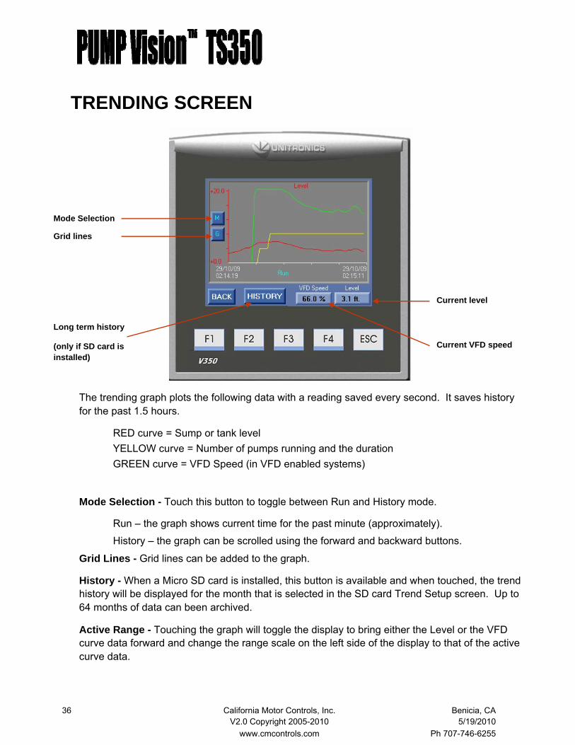
The trending graph plots the following data with a reading saved every second. It saves history for the past 1.5 hours.
RED curve = Sump or tank level YELLOW curve = Number of pumps running and the duration GREEN curve = VFD Speed (in VFD enabled systems)
Mode Selection - Touch this button to toggle between Run and History mode.
Run – the graph shows current time for the past minute (approximately).
History – the graph can be scrolled using the forward and backward buttons.
Grid Lines - Grid lines can be added to the graph.
History - When a Micro SD card is installed, this button is available and when touched, the trend history will be displayed for the month that is selected in the SD card Trend Setup screen. Up to 64 months of data can been archived.
Active Range - Touching the graph will toggle the display to bring either the Level or the VFD curve data forward and change the range scale on the left side of the display to that of the active curve data.
Mode Selection
Grid lines
Long term history
(only if SD card is installed)
Current level
Current VFD speed

37 California Motor Controls, Inc. Benicia, CA V2.0 Copyright 2005-2010 5/19/2010 www.cmcontrols.com Ph 707-746-6255
TREND LOGGING—SD CARD The PUMP Vision has a slot for an optional 8GB Micro SD card. This card is specially formatted for the PUMP Vision and is ordered from California Motor Controls.
This card can store 64 months of trend data due to a limit on the number of files.
To enable the SD card feature:
Insert the SD card into the slot (located) on the upper left side of the controller when viewing the controller from the back).
Access the SD Card Trend Setup screen through MENU>TRENDING>HISTORY>SD SETUP
Touch the yellow “Initialize” button to open a file. The PUMP Vision will automatically start a file with the name format MMYY (month and year). This file will be written to until the end of the current month, at which time the PUMP Vision will automatically start a new file.
The data can be viewed at a any time by touching the File Name button and entering the desired file name, then going to the Trend History screen and scrolling through the data.
It is also possible to retrieve the data and store it to a PC, either by connecting to the PUMP Vi-sion through a serial or Ethernet connection, or by removing the SD card from the PUMP Vision and inserting it into an SD card slot on the personal computer.
Once the data is on the PC, it can be viewed with software available form California Motor Con-trols.
File Name—Enter the file name of the data to be viewed on the Trend History screen. Current file size (size, in bytes, of the file to be displayed) Date created (date of the file to be displayed)
Initialize button (starts a new file) Stop button (stops recording and closes file) Status (Saving or Not Saving) Recording to file (name of file that is being saved to)

38 California Motor Controls, Inc. Benicia, CA V2.0 Copyright 2005-2010 5/19/2010 www.cmcontrols.com Ph 707-746-6255
TREND LOGGING—SD CARD
The Windows based SD Card Manager software allows the user to easily select which month’s file to view on a PC.
Special order versions are available with custom configured trend graphs for other data inputs such as flow, pump run times and other requirements.
Browse
SD CARD INFORMATION
SD card status
Free memory space
Trend folder management. Touch this button to enter a screen that allows old files to be deleted.
39 California Motor Controls, Inc. Benicia, CA V2.0 Copyright 2005-2010 5/19/2010 www.cmcontrols.com Ph 707-746-6255
EVENT LOG—SD CARD
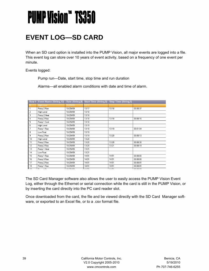
When an SD card option is installed into the PUMP Vision, all major events are logged into a file. This event log can store over 10 years of event activity, based on a frequency of one event per minute.
Events logged:
Pump run—Date, start time, stop time and run duration
Alarms—all enabled alarm conditions with date and time of alarm.
The SD Card Manager software also allows the user to easily access the PUMP Vision Event Log, either through the Ethernet or serial connection while the card is still in the PUMP Vision, or by inserting the card directly into the PC card reader slot.
Once downloaded from the card, the file and be viewed directly with the SD Card Manager soft-ware, or exported to an Excel file, or to a .csv format file.

40 California Motor Controls, Inc. Benicia, CA V2.0 Copyright 2005-2010 5/19/2010 www.cmcontrols.com Ph 707-746-6255
SETTINGS SCREEN
The settings screen displays the operational set points for all pumps and alarms. This is read only.
Scroll Back
The alarm log screen displays the alarm conditions with date and time of occurrence. This log saves the past 1,000 alarm conditions.
There is a separate fault log for each of the VFDs, accessed from the Pump Control screen when the system is in the VFD mode. The VFD logs save the last 250 fault conditions
Scroll Back - Touch this button to scroll back into the alarm history. To return to the top of the log, leave the screen and then return. The log will automatically locate the latest event at the top whenever entering the screen.
Clear Log—Touch this button to clear the fault log. A password screen will pop up that requires the entry of the clear log password, 1234.
ALARMS SCREEN
Constant speed and VFD Proportion mode VFD PID mode
Clear Log
41 California Motor Controls, Inc. Benicia, CA V2.0 Copyright 2005-2010 5/19/2010 www.cmcontrols.com Ph 707-746-6255
TEST MODE SCREEN
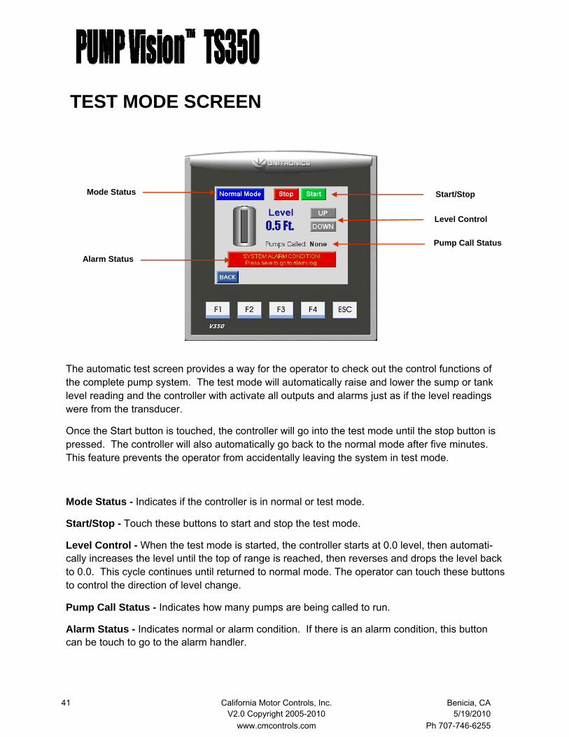
The automatic test screen provides a way for the operator to check out the control functions of the complete pump system. The test mode will automatically raise and lower the sump or tank level reading and the controller with activate all outputs and alarms just as if the level readings were from the transducer.
Once the Start button is touched, the controller will go into the test mode until the stop button is pressed. The controller will also automatically go back to the normal mode after five minutes. This feature prevents the operator from accidentally leaving the system in test mode.
Mode Status - Indicates if the controller is in normal or test mode.
Start/Stop - Touch these buttons to start and stop the test mode.
Level Control - When the test mode is started, the controller starts at 0.0 level, then automati-cally increases the level until the top of range is reached, then reverses and drops the level back to 0.0. This cycle continues until returned to normal mode. The operator can touch these buttons to control the direction of level change.
Pump Call Status - Indicates how many pumps are being called to run.
Alarm Status - Indicates normal or alarm condition. If there is an alarm condition, this button can be touch to go to the alarm handler.
Alarm Status
Start/Stop
Pump Call Status
Level Control
Mode Status

42 California Motor Controls, Inc. Benicia, CA V2.0 Copyright 2005-2010 5/19/2010 www.cmcontrols.com Ph 707-746-6255
ALARM MESSAGE HANDLER
The alarm handler is a series of screens that provides access to active and non-acknowledge alarm conditions. The handler displays information about each alarm condition. This is the first screen that appears when entering the alarm handler and the user must touch the “magnifying glass” button to go to the alarm display page.
Refresh status
Return to previous screen
Go to next level
In the event of an alarm condition, two indica-tions will appear on the main screen.
A text message will be displayed at the top of the screen, indicating the nature of the alarm condition. If multiple conditions exist, touching the text will scroll though all active events. No message is displayed when there is no active alarm.
At the bottom of the screen, a bold red mes-sage indicates that there is an alarm condition. Touching the message bar provides access to the alarm handler.

43 California Motor Controls, Inc. Benicia, CA V2.0 Copyright 2005-2010 5/19/2010 www.cmcontrols.com Ph 707-746-6255
ALARM HANDLER SCREEN 2
The second level of the alarm handler is list of all alarm conditions that are either still active, or are inactive but have not been acknowledged by the operator. Once an alarm is no longer active and it has been acknowledged, it is removed from the list.
Alarm Name - This shows what the alarm condition is.
Status of Alarm - This shows if the alarm has been acknowledged or not.
Refresh Status - Touch this to refresh the list.
Alarm Time - This shows what time the alarm condition occurred.
“Magnifying Glass” - Touch this to go to the next level screen. Each alarm condition has one of these buttons to give access to the level 3 screens and specific information on the alarm status and condition.
Refresh status
Return to previous screen
Go to next level
Alarm name
Status of alarm condition
Alarm time
44 California Motor Controls, Inc. Benicia, CA V2.0 Copyright 2005-2010 5/19/2010 www.cmcontrols.com Ph 707-746-6255
ALARM HANDLER SCREEN 3
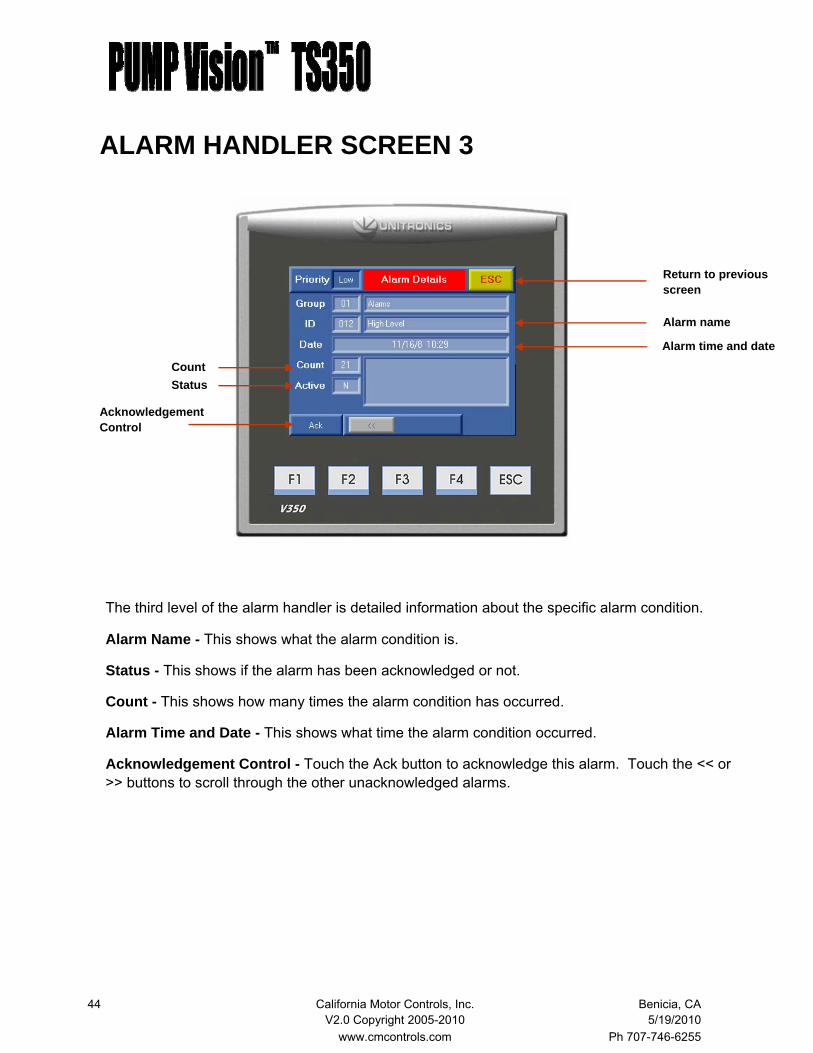
The third level of the alarm handler is detailed information about the specific alarm condition.
Alarm Name - This shows what the alarm condition is.
Status - This shows if the alarm has been acknowledged or not.
Count - This shows how many times the alarm condition has occurred.
Alarm Time and Date - This shows what time the alarm condition occurred.
Acknowledgement Control - Touch the Ack button to acknowledge this alarm. Touch the << or >> buttons to scroll through the other unacknowledged alarms.
Acknowledgement Control
Return to previous screen
Alarm time and date
Count
Alarm name
Status

45 California Motor Controls, Inc. Benicia, CA V2.0 Copyright 2005-2010 5/19/2010 www.cmcontrols.com Ph 707-746-6255
SETUP MENU
LEVEL 1 (password 9876) Pump run set points Alarm configuration LEVEL 2 (password 8144) Pump run set points Alarm configuration System configuration Email SCADA Vision MOTOR Vision
Accessing the Setup Menu requires that a password be entered. Touch the LEVEL 1 or the LEVEL 2 button and the keypad will appear. Enter the password to proceed.
Two levels of access are provided so that the higher level configuration functions can be protected from some users.
DATA ENTRY
The data entry screen will pop up whenever any set point or data entry field is touched. The screen is intuitive. Touch the number buttons to enter a value, touch the ↵ button to enter the value. Touch the Esc button to leave the data entry screen.
46 California Motor Controls, Inc. Benicia, CA V2.0 Copyright 2005-2010 5/19/2010 www.cmcontrols.com Ph 707-746-6255
SETUP MENU
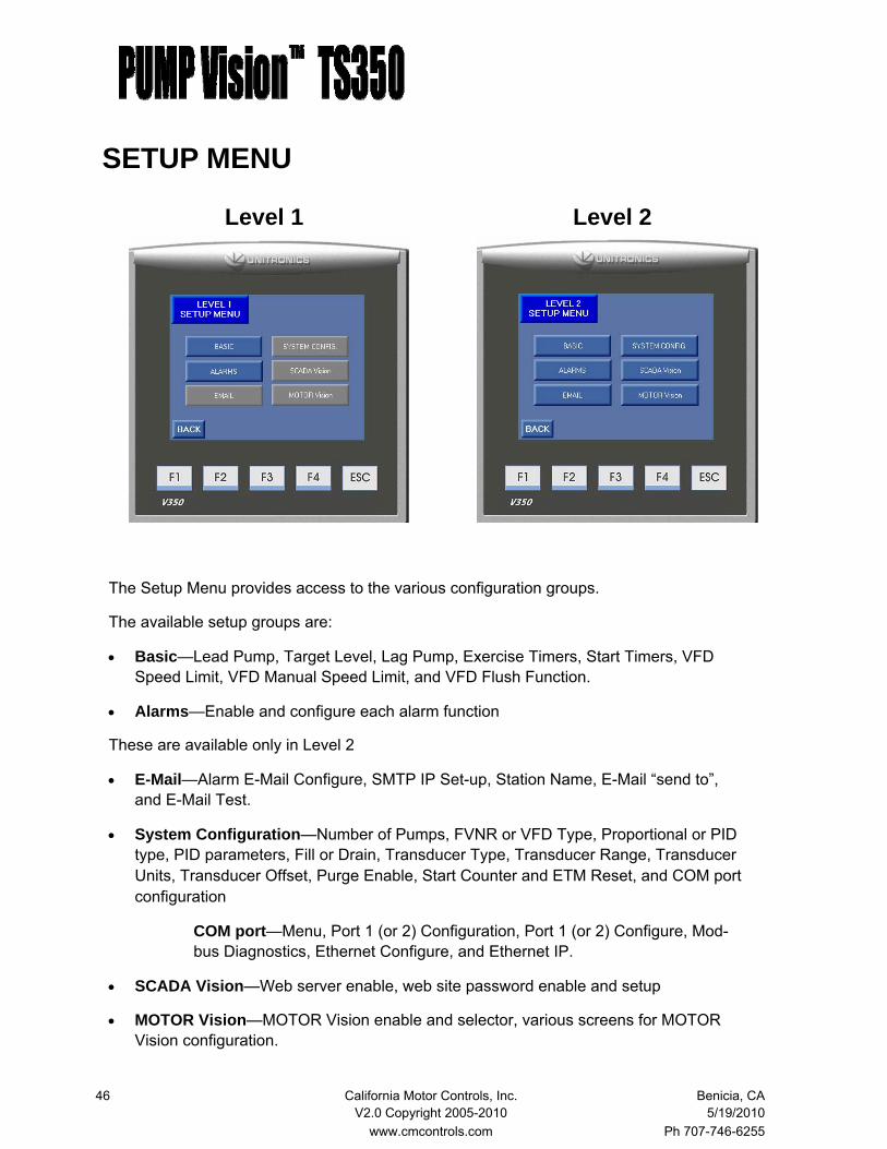
The Setup Menu provides access to the various configuration groups.
The available setup groups are:
• Basic—Lead Pump, Target Level, Lag Pump, Exercise Timers, Start Timers, VFD Speed Limit, VFD Manual Speed Limit, and VFD Flush Function.
• Alarms—Enable and configure each alarm function
These are available only in Level 2
• E-Mail—Alarm E-Mail Configure, SMTP IP Set-up, Station Name, E-Mail “send to”, and E-Mail Test.
• System Configuration—Number of Pumps, FVNR or VFD Type, Proportional or PID type, PID parameters, Fill or Drain, Transducer Type, Transducer Range, Transducer Units, Transducer Offset, Purge Enable, Start Counter and ETM Reset, and COM port configuration
COM port—Menu, Port 1 (or 2) Configuration, Port 1 (or 2) Configure, Mod-bus Diagnostics, Ethernet Configure, and Ethernet IP.
• SCADA Vision—Web server enable, web site password enable and setup
• MOTOR Vision—MOTOR Vision enable and selector, various screens for MOTOR Vision configuration.
Level 1 Level 2
47 California Motor Controls, Inc. Benicia, CA V2.0 Copyright 2005-2010 5/19/2010 www.cmcontrols.com Ph 707-746-6255
BASIC SETUP WIZARD
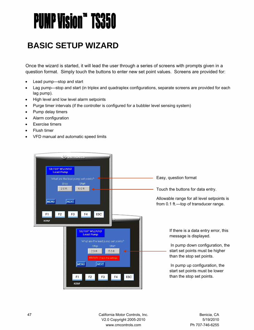
Once the wizard is started, it will lead the user through a series of screens with prompts given in a question format. Simply touch the buttons to enter new set point values. Screens are provided for:
• Lead pump—stop and start • Lag pump—stop and start (in triplex and quadraplex configurations, separate screens are provided for each
lag pump). • High level and low level alarm setpoints • Purge timer intervals (if the controller is configured for a bubbler level sensing system) • Pump delay timers • Alarm configuration • Exercise timers • Flush timer • VFD manual and automatic speed limits
Touch the buttons for data entry.
Allowable range for all level setpoints is from 0.1 ft.—top of transducer range.
Easy, question format
If there is a data entry error, this message is displayed.
In pump down configuration, the start set points must be higher than the stop set points.
In pump up configuration, the start set points must be lower than the stop set points.

48 California Motor Controls, Inc. Benicia, CA V2.0 Copyright 2005-2010 5/19/2010 www.cmcontrols.com Ph 707-746-6255
BASIC SETUP WIZARD—VFD PID MODE
These screens are available for the VFD-PID mode only.
Enter the desired level set point.
The PID function will speed up or slow down the VFDs to maintain this setpoint.
Allowable settings from 0.1ft. - range of transducer
Enter the desired stop and start set points for the lag pump.
In the VFD-PID mode, the lag pumps are se-quenced on and off based on the VFD speed command. When the speed of the pump or pumps that are running rises above the start setpoint, the next lag pump will start after the lag pump start delay timer elapses.
The pumps sequence off in when the speed drops below the stop setpoint.
Allowable settings for start are 20.0% - 100%
Allowable settings for stop are 10.0% - 95.0%
Target Level
Lag Pump

49 California Motor Controls, Inc. Benicia, CA V2.0 Copyright 2005-2010 5/19/2010 www.cmcontrols.com Ph 707-746-6255
BASIC SETUP WIZARD - EXERCISE The Exercise Timer function allows the user to set up each pump individually with an exercise sched-ule. The user can enter settings for:
• Pump exercise frequency • Pump exercise run time • Pump exercise timer status
The individual pump exercise settings are displayed on the Exercise Timer screen as shown below.
Exercise timer status
Exercise run time setting (min:sec)
Exercise frequency setting (hours:min)
When the controller is set to the Constant Speed mode, the pumps will run at full speed when being exercised.
When the controller is set to the VFD mode, the pumps will run at the pre-set manual speed on the Pump Control screen when being exercised.

50 California Motor Controls, Inc. Benicia, CA V2.0 Copyright 2005-2010 5/19/2010 www.cmcontrols.com Ph 707-746-6255
BASIC SETUP WIZARD - PUMP START
Enter the time delay between pump starts.
The pump start delay timer delays the start of the lag pump(s).
The primary purpose of the delay is to stagger the start of all pumps when power is restored after a power failure. This staggered start prevents power surge and voltage drop on the utility system and is especially important when the system is operating on an emergency power gen-erator.
The lead pump start will be delayed until the controller is finished with it’s power on self-test, and then each subsequent pump is delayed by the amount of time set on the start delay timer.
When the PUMP Vision is set up for operating constant speed pumps, or when in the VFD—Proportional mode, the recommended delay time is 3 seconds.
When operating in the VFD-PID mode on 3 and 4 pump systems, it is important to increase to time to at least 20 seconds. The reasons is that lag pumps are sequenced on when the pump or pumps that are running reach a determined speed (set as the lag pump start speed). In VFD systems with more that two pumps, if the time delay is too short, the lag pump that is called to start will not have enough time to ramp up to the current VFD speed command and have an impact on the PID function in time to prevent the next lag pump from starting. It may take some experimentation to determine the best delay time in these systems as there are several factors that come into play. It is recommended that the time be set to the minimum possible without causing all pumps to sequence on unnecessarily.

51 California Motor Controls, Inc. Benicia, CA V2.0 Copyright 2005-2010 5/19/2010 www.cmcontrols.com Ph 707-746-6255
BASIC SETUP WIZARD - VFD MODE
These two screens are only available in the VFD modes, both Proportion Only and PID. With the maximum speed setting, the out flow can be limited if necessary.
It is especially important to tune the minimum speed setpoint to a value that provides smooth system operation based on the pump curve and other factors.
Enter the minimum and maximum speeds that the VFD(s) will be allowed to run. The minimum speed should not be set below the point that the pump will no longer move water. Setting it too low will prevent the pump from stopping.
Allowable settings
Maximum speed from 20% - 100% Minimum speed from 10% - 90%
Enter the maximum speed that the VFD(s) will be allowed to run in the manual mode.
This setting is determined by the pump curve and system constraints and will prevent the pumps from being manually run at a speed greater than what the downstream system can handle.
Allowable settings are from 10% - 100%
VFD Speed Limits
Manual Limit

52 California Motor Controls, Inc. Benicia, CA V2.0 Copyright 2005-2010 5/19/2010 www.cmcontrols.com Ph 707-746-6255
BASIC SETUP WIZARD
This function is available in VFD modes and will enable the pumps to run at maximum speed for the time set on the duration timer to flush the lines.
When the pump stop command is triggered, the VFD will ramp its speed to the maximum speed set-point and run for the period of time set on the duration timer. Once the duration timer elapses, the pump will shut down.
This function will flush the lines.
Touch the Enable/Disable button to en-able or disable this function.
Set the duration time in Minutes:Seconds
Set the cycle time in Hours:Minutes
Set the duration time in Seconds
Purge Timers
Flush Timers
This screen is only available if the purge function is en-abled in the Advanced Setup menu.
This function operates a purge solenoid valve that when energized will allow compressed air to release into the bubbler tube for the purpose of clearing any debris from the tube. This function also serves to recharge the air in a trapped air system.
53 California Motor Controls, Inc. Benicia, CA V2.0 Copyright 2005-2010 5/19/2010 www.cmcontrols.com Ph 707-746-6255
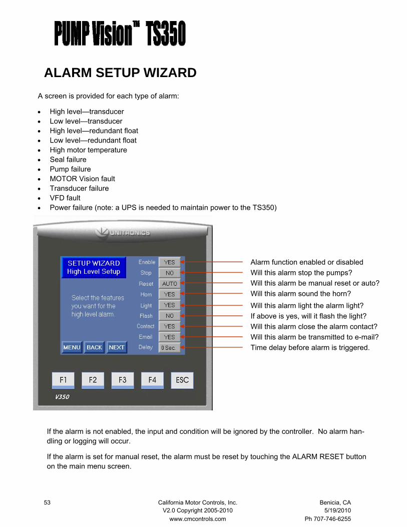
ALARM SETUP WIZARD A screen is provided for each type of alarm:
• High level—transducer • Low level—transducer • High level—redundant float • Low level—redundant float • High motor temperature • Seal failure • Pump failure • MOTOR Vision fault • Transducer failure • VFD fault • Power failure (note: a UPS is needed to maintain power to the TS350)
Alarm function enabled or disabled Will this alarm stop the pumps? Will this alarm be manual reset or auto? Will this alarm sound the horn? Will this alarm light the alarm light? If above is yes, will it flash the light? Will this alarm close the alarm contact?
Time delay before alarm is triggered.
If the alarm is not enabled, the input and condition will be ignored by the controller. No alarm han-dling or logging will occur.
If the alarm is set for manual reset, the alarm must be reset by touching the ALARM RESET button on the main menu screen.
Will this alarm be transmitted to e-mail?
54 California Motor Controls, Inc. Benicia, CA V2.0 Copyright 2005-2010 5/19/2010 www.cmcontrols.com Ph 707-746-6255
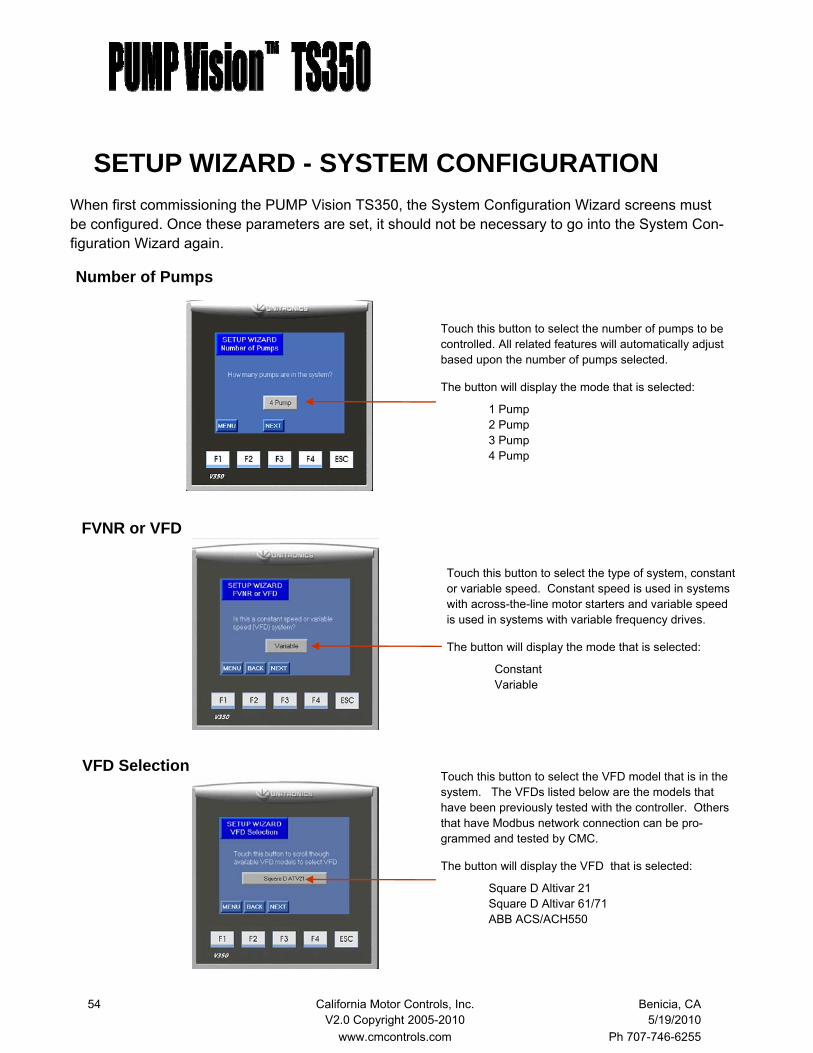
When first commissioning the PUMP Vision TS350, the System Configuration Wizard screens must be configured. Once these parameters are set, it should not be necessary to go into the System Con-figuration Wizard again.
Touch this button to select the number of pumps to be controlled. All related features will automatically adjust based upon the number of pumps selected.
The button will display the mode that is selected:
1 Pump 2 Pump 3 Pump 4 Pump
Touch this button to select the type of system, constant or variable speed. Constant speed is used in systems with across-the-line motor starters and variable speed is used in systems with variable frequency drives.
The button will display the mode that is selected:
Constant Variable
Number of Pumps
FVNR or VFD
Touch this button to select the VFD model that is in the system. The VFDs listed below are the models that have been previously tested with the controller. Others that have Modbus network connection can be pro-grammed and tested by CMC.
The button will display the VFD that is selected:
Square D Altivar 21 Square D Altivar 61/71 ABB ACS/ACH550
VFD Selection
SETUP WIZARD - SYSTEM CONFIGURATION
55 California Motor Controls, Inc. Benicia, CA V2.0 Copyright 2005-2010 5/19/2010 www.cmcontrols.com Ph 707-746-6255
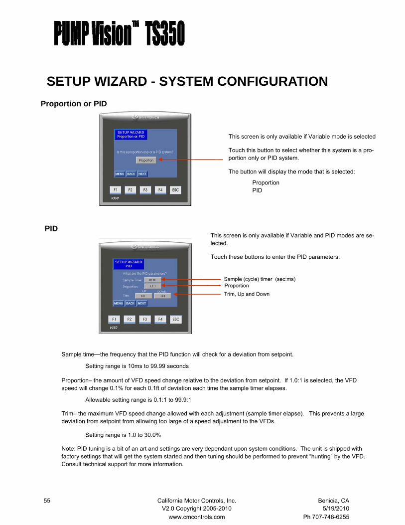
This screen is only available if Variable and PID modes are se-lected.
Touch these buttons to enter the PID parameters.
PID
Sample time—the frequency that the PID function will check for a deviation from setpoint.
Setting range is 10ms to 99.99 seconds
Proportion– the amount of VFD speed change relative to the deviation from setpoint. If 1.0:1 is selected, the VFD speed will change 0.1% for each 0.1ft of deviation each time the sample timer elapses.
Allowable setting range is 0.1:1 to 99.9:1
Trim– the maximum VFD speed change allowed with each adjustment (sample timer elapse). This prevents a large deviation from setpoint from allowing too large of a speed adjustment to the VFDs.
Setting range is 1.0 to 30.0%
Note: PID tuning is a bit of an art and settings are very dependant upon system conditions. The unit is shipped with factory settings that will get the system started and then tuning should be performed to prevent “hunting” by the VFD. Consult technical support for more information.
Sample (cycle) timer (sec:ms) Proportion Trim, Up and Down
This screen is only available if Variable mode is selected
Touch this button to select whether this system is a pro-portion only or PID system.
The button will display the mode that is selected:
Proportion PID
Proportion or PID
SETUP WIZARD - SYSTEM CONFIGURATION
56 California Motor Controls, Inc. Benicia, CA V2.0 Copyright 2005-2010 5/19/2010 www.cmcontrols.com Ph 707-746-6255
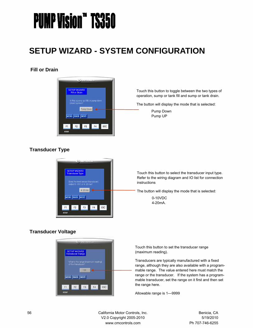
Touch this button to set the transducer range (maximum reading).
Transducers are typically manufactured with a fixed range, although they are also available with a program-mable range. The value entered here must match the range or the transducer. If the system has a program-mable transducer, set the range on it first and then set the range here.
Allowable range is 1—9999
Touch this button to select the transducer input type. Refer to the wiring diagram and IO list for connection instructions
The button will display the mode that is selected:
0-10VDC 4-20mA.
Transducer Type
Transducer Voltage
Touch this button to toggle between the two types of operation, sump or tank fill and sump or tank drain.
The button will display the mode that is selected:
Pump Down Pump UP
Fill or Drain
SETUP WIZARD - SYSTEM CONFIGURATION

57 California Motor Controls, Inc. Benicia, CA V2.0 Copyright 2005-2010 5/19/2010 www.cmcontrols.com Ph 707-746-6255
SETUP WIZARD - SYSTEM CONFIGURATION
Touch this button to set how far the transducer (or bub-bler tube) is from the bottom of the tank or sump.
This offset is added to the level reported by the trans-ducer so that the displayed level is accurate.
Allowable setting range is from 0.0 to 99.9 feet.
Note: Do not enter any pump start/stop or alarm level setpoints for a value less than the offset value as the operating level cannot drop below the offset.
Level Offset
Purge Enable
Touch this button to enable the bubbler purge solenoid output.
When enabled, a screen becomes available in the Ba-sic Setup menu that allows access to the purge cycle and duration timers.
The button will display the mode that is selected:
Yes No
Touch this button to set the units of measurement used by the transducer, in PSI or inches of water.
If PSI is selected, the PUMP Vision will automatically convert the range to tenths of feet of water. For exam-ple, a range of 15 PSI will result in a maximum level display of 34.6 ft.
The button will display the mode that is selected:
Inches PSI
Transducer Units
58 California Motor Controls, Inc. Benicia, CA V2.0 Copyright 2005-2010 5/19/2010 www.cmcontrols.com Ph 707-746-6255
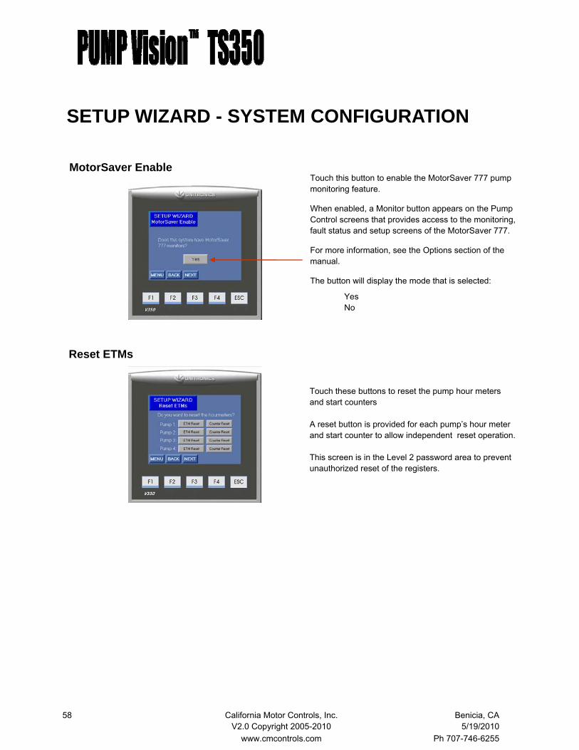
Reset ETMs
Touch these buttons to reset the pump hour meters and start counters A reset button is provided for each pump’s hour meter and start counter to allow independent reset operation. This screen is in the Level 2 password area to prevent unauthorized reset of the registers.
MotorSaver Enable Touch this button to enable the MotorSaver 777 pump monitoring feature.
When enabled, a Monitor button appears on the Pump Control screens that provides access to the monitoring, fault status and setup screens of the MotorSaver 777.
For more information, see the Options section of the manual.
The button will display the mode that is selected:
Yes No
SETUP WIZARD - SYSTEM CONFIGURATION
59 California Motor Controls, Inc. Benicia, CA V2.0 Copyright 2005-2010 5/19/2010 www.cmcontrols.com Ph 707-746-6255
COMMUNICATION
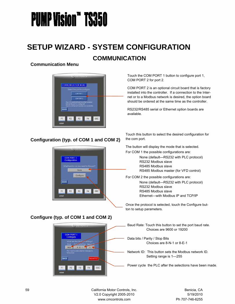
Touch the COM PORT 1 button to configure port 1, COM PORT 2 for port 2.
COM PORT 2 is an optional circuit board that is factory installed into the controller. If a connection to the Inter-net or to a Modbus network is desired, the option board should be ordered at the same time as the controller.
RS232/RS485 serial or Ethernet option boards are available.
Touch this button to select the desired configuration for the com port.
The button will display the mode that is selected. For COM 1 the possible configurations are: None (default—RS232 with PLC protocol) RS232 Modbus slave RS485 Modbus slave RS485 Modbus master (for VFD control)
For COM 2 the possible configurations are: None (default—RS232 with PLC protocol) RS232 Modbus slave RS485 Modbus slave Ethernet—with Modbus IP and TCP/IP Once the protocol is selected, touch the Configure but-ton to setup parameters.
Baud Rate: Touch this button to set the port baud rate. Choices are 9600 or 19200 Data bits / Parity / Stop Bits Choices are 8-N-1 or 8-E-1 Network ID: This button sets the Modbus network ID. Setting range is 1—255 Power cycle the PLC after the selections have been made.
Communication Menu
Configuration (typ. of COM 1 and COM 2)
Configure (typ. of COM 1 and COM 2)
SETUP WIZARD - SYSTEM CONFIGURATION
60 California Motor Controls, Inc. Benicia, CA V2.0 Copyright 2005-2010 5/19/2010 www.cmcontrols.com Ph 707-746-6255
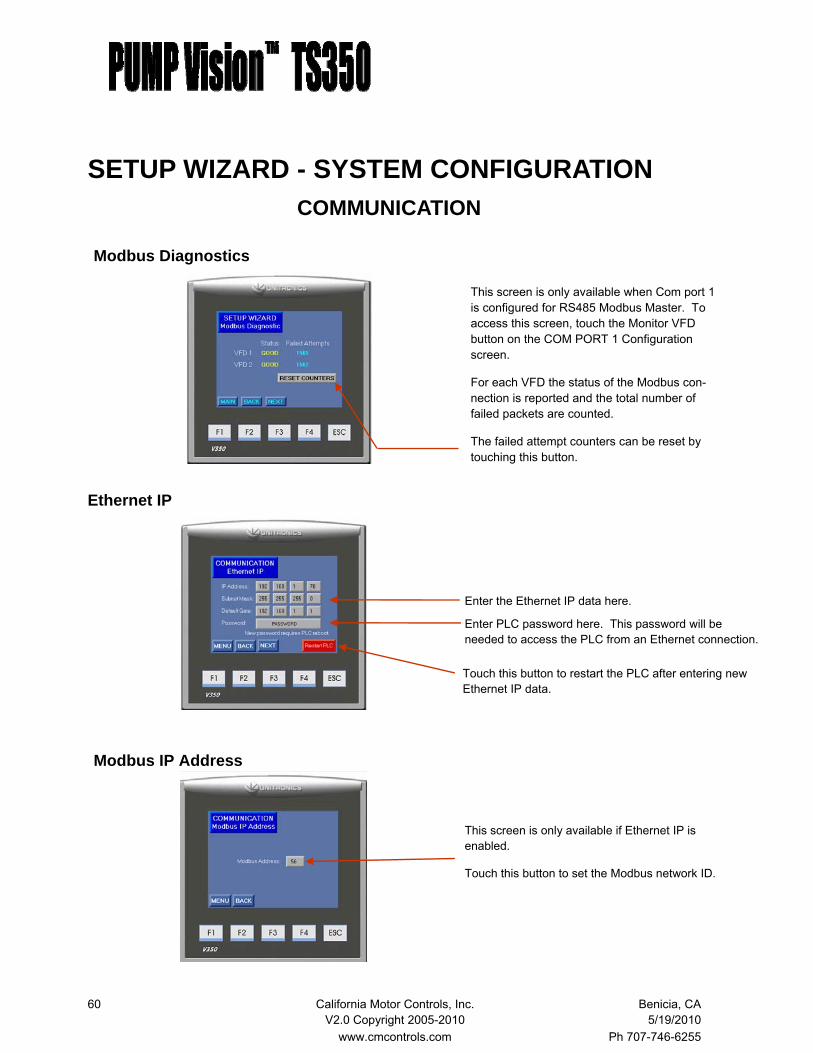
This screen is only available when Com port 1 is configured for RS485 Modbus Master. To access this screen, touch the Monitor VFD button on the COM PORT 1 Configuration screen.
For each VFD the status of the Modbus con-nection is reported and the total number of failed packets are counted.
The failed attempt counters can be reset by touching this button.
Enter the Ethernet IP data here.
Touch this button to restart the PLC after entering new Ethernet IP data.
Modbus Diagnostics
Ethernet IP
Modbus IP Address
This screen is only available if Ethernet IP is enabled.
Touch this button to set the Modbus network ID.
Enter PLC password here. This password will be needed to access the PLC from an Ethernet connection.
SETUP WIZARD - SYSTEM CONFIGURATION COMMUNICATION
61 California Motor Controls, Inc. Benicia, CA V2.0 Copyright 2005-2010 5/19/2010 www.cmcontrols.com Ph 707-746-6255
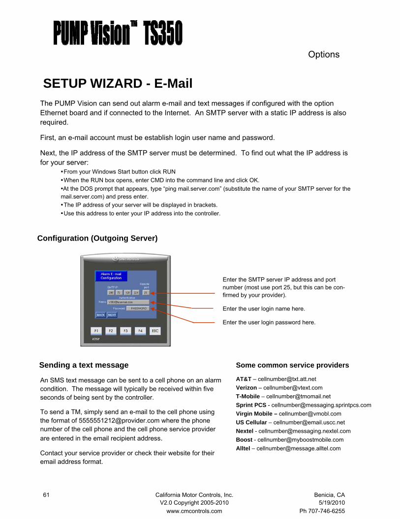
SETUP WIZARD - E-Mail
Configuration (Outgoing Server)
Enter the SMTP server IP address and port number (most use port 25, but this can be con-firmed by your provider).
Enter the user login name here.
Enter the user login password here.
The PUMP Vision can send out alarm e-mail and text messages if configured with the option Ethernet board and if connected to the Internet. An SMTP server with a static IP address is also required.
First, an e-mail account must be establish login user name and password.
Next, the IP address of the SMTP server must be determined. To find out what the IP address is for your server:
From your Windows Start button click RUN When the RUN box opens, enter CMD into the command line and click OK. At the DOS prompt that appears, type “ping mail.server.com” (substitute the name of your SMTP server for the mail.server.com) and press enter. The IP address of your server will be displayed in brackets. Use this address to enter your IP address into the controller.
Sending a text message
An SMS text message can be sent to a cell phone on an alarm condition. The message will typically be received within five seconds of being sent by the controller.
To send a TM, simply send an e-mail to the cell phone using the format of [email protected] where the phone number of the cell phone and the cell phone service provider are entered in the email recipient address.
Contact your service provider or check their website for their email address format.
AT&T – [email protected] Verizon – [email protected] T-Mobile – [email protected] Sprint PCS - [email protected] Virgin Mobile – [email protected] US Cellular – [email protected] Nextel - [email protected] Boost - [email protected] Alltel – [email protected]
Some common service providers
Options
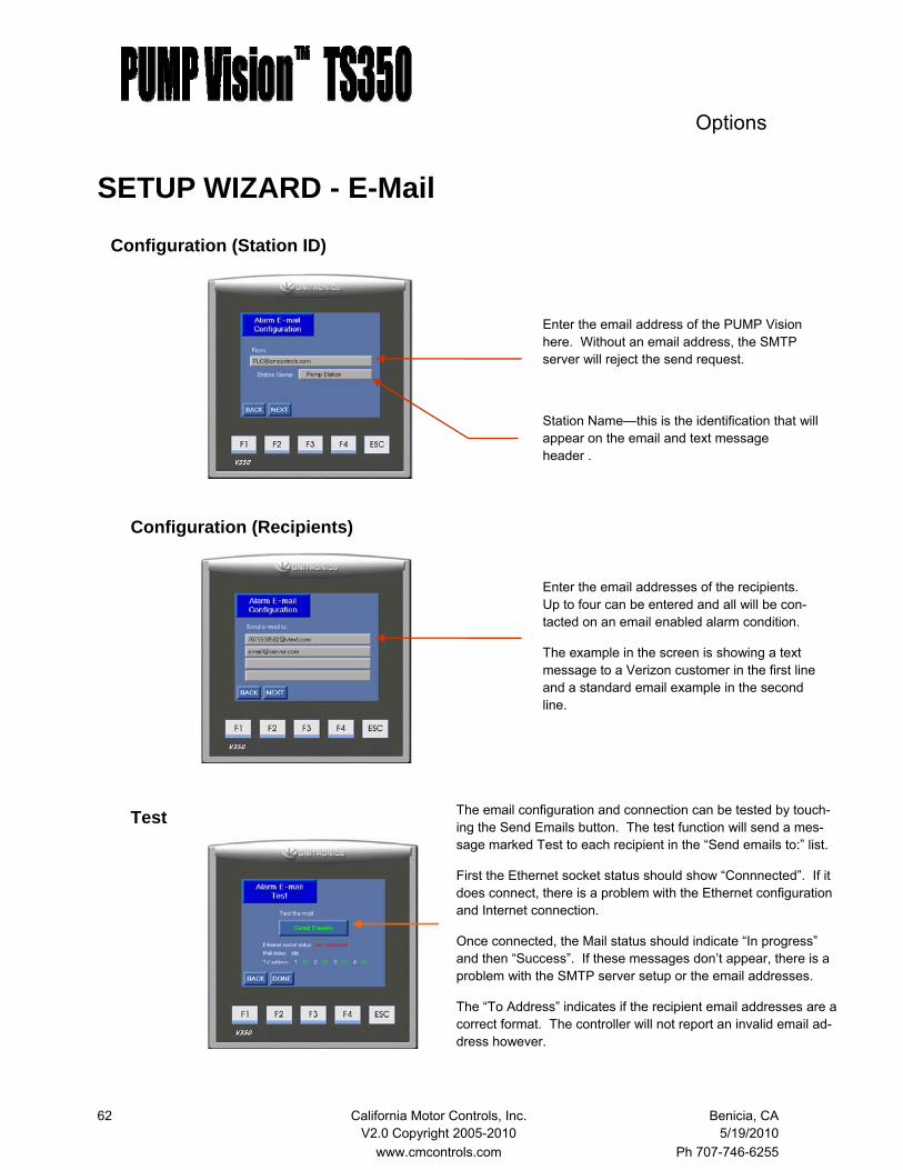
62 California Motor Controls, Inc. Benicia, CA V2.0 Copyright 2005-2010 5/19/2010 www.cmcontrols.com Ph 707-746-6255
Configuration (Recipients)
Test
Configuration (Station ID)
SETUP WIZARD - E-Mail
Enter the email address of the PUMP Vision here. Without an email address, the SMTP server will reject the send request.
Station Name—this is the identification that will appear on the email and text message header .
Enter the email addresses of the recipients. Up to four can be entered and all will be con-tacted on an email enabled alarm condition.
The example in the screen is showing a text message to a Verizon customer in the first line and a standard email example in the second line.
The email configuration and connection can be tested by touch-ing the Send Emails button. The test function will send a mes-sage marked Test to each recipient in the “Send emails to:” list.
First the Ethernet socket status should show “Connnected”. If it does connect, there is a problem with the Ethernet configuration and Internet connection.
Once connected, the Mail status should indicate “In progress” and then “Success”. If these messages don’t appear, there is a problem with the SMTP server setup or the email addresses.
The “To Address” indicates if the recipient email addresses are a correct format. The controller will not report an invalid email ad-dress however.
Options
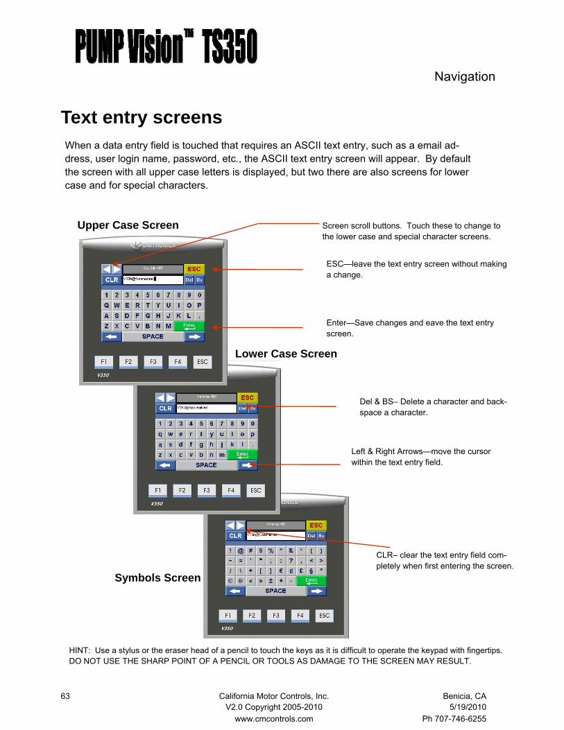
63 California Motor Controls, Inc. Benicia, CA V2.0 Copyright 2005-2010 5/19/2010 www.cmcontrols.com Ph 707-746-6255
Text entry screens
Screen scroll buttons. Touch these to change to the lower case and special character screens.
When a data entry field is touched that requires an ASCII text entry, such as a email ad-dress, user login name, password, etc., the ASCII text entry screen will appear. By default the screen with all upper case letters is displayed, but two there are also screens for lower case and for special characters.
ESC—leave the text entry screen without making a change.
Enter—Save changes and eave the text entry screen.
Navigation
Upper Case Screen
Lower Case Screen
Symbols Screen
Del & BS– Delete a character and back-space a character.
Left & Right Arrows—move the cursor within the text entry field.
CLR– clear the text entry field com-pletely when first entering the screen.
HINT: Use a stylus or the eraser head of a pencil to touch the keys as it is difficult to operate the keypad with fingertips. DO NOT USE THE SHARP POINT OF A PENCIL OR TOOLS AS DAMAGE TO THE SCREEN MAY RESULT.

64 California Motor Controls, Inc. Benicia, CA V2.0 Copyright 2005-2010 5/19/2010 www.cmcontrols.com Ph 707-746-6255
The MOTOR Vision System
The PUMP Vision can communicate with smart motor starter via a Modbus connection that enables the PUMP Vision to display a variety of important pump and motor information.
Depending on the type of MOTOR Vision starter that is connected, the PUMP Vision can display:
Current per phase, average and imbalance Voltage per phase, average and imbalance Ground fault, power factor and frequency Trip and fault information
TMMOTOR Vision
Various motor controllers are able to connect to the PUMP Vision as MOTOR Vision devices, including:
Variable frequency drives RVSS starters Insight overload and power monitor U-Line integrated motor starter

65 California Motor Controls, Inc. Benicia, CA V2.0 Copyright 2005-2010 5/19/2010 www.cmcontrols.com Ph 707-746-6255
MOTOR Vision U-Line Starter
Controller status
The PUMP Vision is programmed to communicate with the Schneider (Square D) U-Line products via a Modbus connection that enables the PUMP Vision to display current, ground fault, and a variety of trip in-formation.
Two monitoring screens are provided for each pump in the system that provide access to:
Current information Trip and fault information
Options—U-Line
Current display Current for each phase. Average current across all phases. Imbalance between phases.
Other OL set point Thermal (overload) percent of trip Ground fault percent of total current
Monitoring
Access to fault screen
Status—the status indicator gives the status of the MotorSaver at a glance. Green—Normal, output relay on, pump can run. Yellow—Warning, trip may be imminent. Red—Tripped, pump is shutdown, fault must be cleared.
TMMOTOR Vision

66 California Motor Controls, Inc. Benicia, CA V2.0 Copyright 2005-2010 5/19/2010 www.cmcontrols.com Ph 707-746-6255
MOTOR Vision U-Line Starter
Controller status
The PUMP Vision is programmed to communicate with the Schneider (Square D) U-Line products via a Modbus connection that enables the PUMP Vision to display current, ground fault, and a variety of trip in-formation.
Two monitoring screens are provided for each pump in the system that provide access to:
Current information Trip and fault information
Options—U-Line
Current display Current for each phase. Average current across all phases. Imbalance between phases.
Other OL set point Thermal (overload) percent of trip Ground fault percent of total current
Monitoring
Access to fault screen
Status—the status indicator gives the status of the MotorSaver at a glance. Green—Normal, output relay on, pump can run. Yellow—Warning, trip may be imminent. Red—Tripped, pump is shutdown, fault must be cleared.
TMMOTOR Vision

67 California Motor Controls, Inc. Benicia, CA V2.0 Copyright 2005-2010 5/19/2010 www.cmcontrols.com Ph 707-746-6255
MOTOR Vision Insight Power Monitor
Voltage display Voltage between each phase. Average voltage across all phases. Imbalance between phases.
The PUMP Vision is programmed to communicate with the Eaton Insight power monitor/overload relay via a Modbus connection that enables the PUMP Vi-sion to display volts, current, ground fault, power fac-tor and a variety of trip information.
Three screens are provided for each pump in the system that provide access to:
Current and voltage information Trip and fault information - page 1 and 2
Options—Power Monitor
Current display Voltage between each phase. Average voltage across all phases. Imbalance between phases.
Other Frequency Kilowatts Power factor Ground fault
Monitoring
Access to fault screen
Status—the status indicator gives the status of the MotorSaver at a glance. Green—Normal, output relay on, pump can run. Yellow—Warning, trip may be imminent. Red—Tripped, pump is shutdown, fault must be cleared.
TMMOTOR Vision

68 California Motor Controls, Inc. Benicia, CA V2.0 Copyright 2005-2010 5/19/2010 www.cmcontrols.com Ph 707-746-6255
Options—Power Monitor
Fault Status - Page 1
Reset Button
Press this button to reset the MotorSaver after a fault condition.
This screen displays the status of the Insight’s protective functions. Trip Reason—When the Insight detects any of these faults, the output of the Insight will trip. If that contact is wired into the contactor circuit, the pump will be shut down. The PUMP Vision output to the starter will also be turned off if selected to do so in the MO-TOR Vision Insight alarm setup screen
Warnings—The alarms in this category are imminent failures. They do not cause immediate trips, but will cause a trip indirectly by affecting a related condition trip.
The pump will not start if any of the warning conditions exist prior to starting.
The function’s Mode and Enable conditions are displayed. These features are setup with the MOTOR Vision setup wizard.
The Insight protects, either directly or indi-rectly, against the following conditions:
Contactor failure (line voltage but single phase current) Overload Ground fault Single phase voltage Phase reversal Over voltage Under voltage
MOTOR Vision Insight Power Monitor

69 California Motor Controls, Inc. Benicia, CA V2.0 Copyright 2005-2010 5/19/2010 www.cmcontrols.com Ph 707-746-6255
Options—Power Monitor
Fault Status - Page 2
Reset Button
Press this button to reset the MotorSaver after a fault condition.
This screen displays the status of the Insight’s protective functions. Trip Reason—When the Insight detects any of these faults, the output of the Insight will trip. If that contact is wired into the contactor circuit, the pump will be shut down. The PUMP Vision output to the starter will also be turned off if selected to do so in the MO-TOR Vision Insight alarm setup screen
Warnings—The alarms in this category are imminent failures. They do not cause immediate trips, but will cause a trip indirectly by affecting a related condition trip.
The pump will not start if any of the warning conditions exist prior to starting.
The function’s Mode and Enable conditions are displayed. These features are setup with the MOTOR Vision setup wizard.
All warning and trip conditions are logged into the event log.
The Insight protects, either directly or indi-rectly, against the following conditions:
Under current (pump running dry) Current imbalance Voltage imbalance High power Low power Mechanical jam
MOTOR Vision Insight Power Monitor

70 California Motor Controls, Inc. Benicia, CA V2.0 Copyright 2005-2010 5/19/2010 www.cmcontrols.com Ph 707-746-6255
MOTOR Vision SETUP WIZARD When first commissioning the PUMP Vision TS350 that has MOTOR Vision connected, the MO-TOR Vision Configuration Wizard screens must be configured. Once these parameters are set, it should not be necessary to go into the MOTOR Vision Configuration Wizard again
The PUMP Vision must be configure to communicate with the MOTOR Vision products. First, the COM 1 port must be configured as an RS485 Modbus master (see System Configuration - Communication).
Then the MOTOR Vision starter must be connected with a Modbus network to the PUMP Vi-sion com port. For connection instructions, refer to RS485 wiring instructions.
The Modbus address must be properly configured on the MOTOR Vision starter.
Pump 1 motor controller must be set to Modbus address 11 Pump 2 motor controller must be set to Modbus address 12 Pump 3 motor controller must be set to Modbus address 13 Pump 4 motor controller must be set to Modbus address 14
Finally, the MOTOR Vision configuration wizard must be run. The first screen that appears provides for the selection of the MOTOR Vision starter type.
Options—MOTOR Vision
Touch this button to scroll through the MOTOR Vision starter choices None - no MOTOR Vision connected TeSys U-Line - Schneider U-Line integrated starter Eaton Insight - Cutler-Hammer overload/power monitor
TMMOTOR Vision
U-Line Insight

71 California Motor Controls, Inc. Benicia, CA V2.0 Copyright 2005-2010 5/19/2010 www.cmcontrols.com Ph 707-746-6255
.
Prior to configuring the MOTOR Vision, Modbus communication between the PUMP Vision and MOTOR Vision must be established.
This screen sets the motor overload for Pump 1. Sepa-rate screens are provided for each pump in the system.
Full Load Amps - set the FLA to the motor nameplate data. The acceptable range is displayed according to the trip module that is installed in the motor starter. Trip Class - set the desired trip class (usually class 10 for submersible pumps). The value must be set for either 5, 10, 15, 20, 25 or 30) Short Circuit - set the short circuit trip (also known as the magnetic trip). This should be set at 1000% (of full load amps). If the starter trips on starting
If the PUMP Vision controller is not communicating properly with one (or all) of the MOTOR Vision starters, this warning screen will appear. While the subsequent setup screens can be accessed, any changes that are entered into the PUMP Vision will not be written to the MOTOR Vision starter(s) that are not connected.
Set the overload
Communication Error
SETUP WIZARD - MOTOR Vision U-Line

72 California Motor Controls, Inc. Benicia, CA V2.0 Copyright 2005-2010 5/19/2010 www.cmcontrols.com Ph 707-746-6255
.
For all of the function trip and warning set point screens, the values entered apply to all of the pumps in the system.
This screen sets the motor under current. This condi-tion generally means that the pump is running dry.
Warning - when the motor current drops below the set point, the warning alarm will trigger, if the function is enabled. Trip - when the motor current drops below the set point, the starter will trip off, if the function is enabled. Trip delay - This timer delays the trip fault.
Under Current
SETUP WIZARD - MOTOR Vision U-Line
This screen sets the motor thermal overload warning. A thermal warning generally indicates that there is a problem in the motor or pump, such as bearing wear.
Warning - when the motor current rises above this set point (percentage of the FLA value entered on the over-load setup page) the warning alarm will trigger, if the function is enabled. Reset - When the current drops below this setting, the warning will reset Reset delay: The current must stay below the reset set point for this time in order for the warning to reset.
Thermal trip
This screen sets the motor ground fault. This condition generally means that there is a problem with the motor winding or cable insulation.
Warning - when the ground leakage current rises above the set point, the warning alarm will trigger, if the func-tion is enabled. Trip - when the ground leakage current rises above the set point, the starter will trip off, if the function is en-abled. Trip delay - This timer delays the trip fault.
Ground Fault

73 California Motor Controls, Inc. Benicia, CA V2.0 Copyright 2005-2010 5/19/2010 www.cmcontrols.com Ph 707-746-6255
.
For all of the function trip and warning set point screens, the values entered apply to all of the pumps in the system.
This screen sets the current at which the starter senses a mechanical jam. This could be cause by foreign de-bris in the pump.
Warning - when the motor current rises above the set point, the warning alarm will trigger, if the function is enabled. Trip - when the motor current rises above the set point, the starter will trip off, if the function is enabled. Trip delay - This timer delays the trip fault.
Mechanical Jam
SETUP WIZARD - MOTOR Vision U-Line
This screen sets motor current imbalance. The condi-tion can mean a bad motor winding, failed conductor, failed contactor or other cause for a significant differ-ence in current per phase.
Warning - when the motor current imbalance rises above this set point the warning alarm will trigger, if the function is enabled. Trip - when the motor current imbalance rises above the set point, the starter will trip off, if the function is enabled. Trip delay - This timer delays the trip fault.
Current Imbalance
This screen sets the long start fault. This condition generally means that there is a mechanical problem with the pump.
Warning - when the current during pump start rises above the set point, the warning alarm will trigger, if the function is enabled. Trip - when the current during pump start rises above the set point, the starter will trip off, if the function is enabled. Trip delay - This timer delays the trip fault.
Long Start
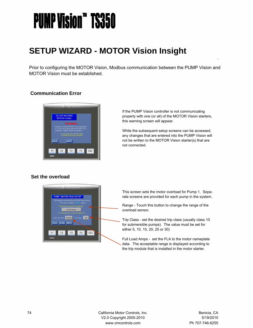
74 California Motor Controls, Inc. Benicia, CA V2.0 Copyright 2005-2010 5/19/2010 www.cmcontrols.com Ph 707-746-6255
.
Prior to configuring the MOTOR Vision, Modbus communication between the PUMP Vision and MOTOR Vision must be established.
This screen sets the motor overload for Pump 1. Sepa-rate screens are provided for each pump in the system.
Range - Touch this button to change the range of the overload sensor. Trip Class - set the desired trip class (usually class 10 for submersible pumps). The value must be set for either 5, 10, 15, 20, 25 or 30) Full Load Amps - set the FLA to the motor nameplate data. The acceptable range is displayed according to the trip module that is installed in the motor starter.
If the PUMP Vision controller is not communicating properly with one (or all) of the MOTOR Vision starters, this warning screen will appear. While the subsequent setup screens can be accessed, any changes that are entered into the PUMP Vision will not be written to the MOTOR Vision starter(s) that are not connected.
Set the overload
Communication Error
SETUP WIZARD - MOTOR Vision Insight

75 California Motor Controls, Inc. Benicia, CA V2.0 Copyright 2005-2010 5/19/2010 www.cmcontrols.com Ph 707-746-6255
.
For all of the Insight set point screens, the values entered apply to all of the pumps in the system.
This screen sets the current at which the starter senses a mechanical jam. This could be cause by foreign de-bris in the pump.
Threshold - when the motor rises above the set point, the alarm will trigger, if the function is enabled. Enable - touch this button to toggle between enable and disable Trip delay - This timer delays the trip fault.
Mechanical Jam
SETUP WIZARD - MOTOR Vision Insight
This screen sets the restart delay and attempts charac-teristics for the various functions.
Motor Fault - including Mechanical Jam, Current Imbal-ance and Overload - reset time delay and number of restart attempts (touch the attempts button to scroll through) Load Fault - including Under Current, Low Power and High Power - reset time delay and number of restart attempts (touch the attempts button to scroll through) Line Fault - including Under Voltage, Over Voltage and Voltage Imbalance - reset time delay.
Restart
This screen sets motor current imbalance. The condi-tion can mean a bad motor winding, failed conductor, failed contactor or other cause for a significant differ-ence in current per phase.
Threshold - when the motor current imbalance rises above the set point, the alarm will trigger, if the func-tion is enabled. Enable - touch this button to toggle between enable and disable Trip delay - This timer delays the trip fault.
Current Imbalance

76 California Motor Controls, Inc. Benicia, CA V2.0 Copyright 2005-2010 5/19/2010 www.cmcontrols.com Ph 707-746-6255
.
For all of the Insight set point screens, the values entered apply to all of the pumps in the system.
This screen sets the phase rotation for the incoming power.
Threshold - touch this button to scroll between ABC, ACB, or None. Enable - touch this button to toggle between enable and disable Mode - Touch this button to toggle between trip and alarm mode. NOTE: This setting also affects the Over-Voltage, Under-Voltage and Voltage Imbalance func-tions.
Phase Rotation
SETUP WIZARD - MOTOR Vision Insight
This screen sets the motor ground fault. This condition generally means that there is a problem with the motor winding or cable insulation.
Threshold - when the ground leak current rises above the set point, the alarm will trigger, if the function is enabled. Enable - touch this button to toggle between enable and disable Trip delay - This timer delays the trip fault. Mode - Touch this button to toggle between trip and alarm only mode.
Ground Fault
This screen sets the motor under current. This condi-tion generally means that the pump is running dry.
Threshold - when the motor current falls below the set point, the alarm will trigger, if the function is enabled. Enable - touch this button to toggle between enable and disable Trip delay - This timer delays the trip fault.
Under Current

77 California Motor Controls, Inc. Benicia, CA V2.0 Copyright 2005-2010 5/19/2010 www.cmcontrols.com Ph 707-746-6255
.
For all of the Insight set point screens, the values entered apply to all of the pumps in the system.
This screen sets the high power fault. This condition generally means that the pump or motor has mechani-cal problems.
Threshold - when the motor KW rises above the set point, the alarm will trigger, if the function is enabled. Enable - touch this button to toggle between enable and disable Trip delay - This timer delays the trip fault.
High Power
SETUP WIZARD - MOTOR Vision Insight
This screen sets the low power fault. This condition generally means that the pump is running dry or that the pump is broken.
Threshold - when the motor KW drops below the set point, the alarm will trigger, if the function is enabled. Enable - touch this button to toggle between enable and disable Trip delay - This timer delays the trip fault.
Low Power
This screen sets under voltage. The condition is caused by low voltage from the power source.
Threshold - when the voltage drops below the set point, the alarm will trigger, if the function is enabled. Enable - touch this button to toggle between enable and disable
Under Voltage
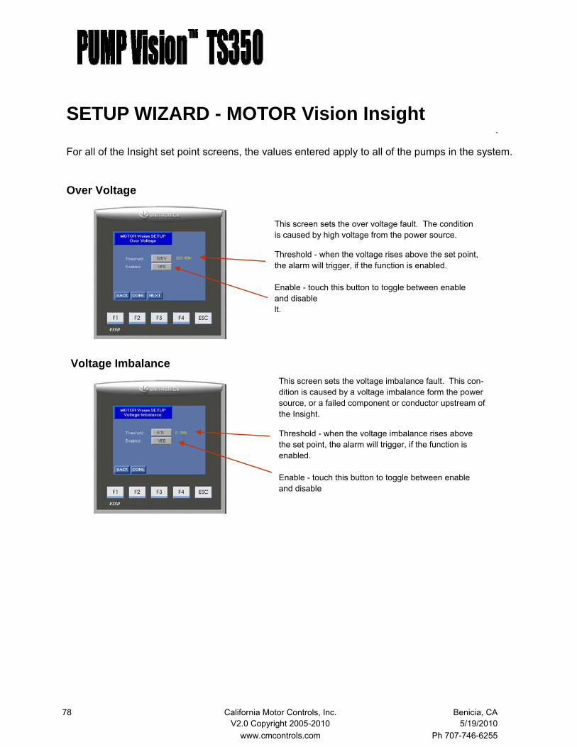
78 California Motor Controls, Inc. Benicia, CA V2.0 Copyright 2005-2010 5/19/2010 www.cmcontrols.com Ph 707-746-6255
.
For all of the Insight set point screens, the values entered apply to all of the pumps in the system.
This screen sets the voltage imbalance fault. This con-dition is caused by a voltage imbalance form the power source, or a failed component or conductor upstream of the Insight.
Threshold - when the voltage imbalance rises above the set point, the alarm will trigger, if the function is enabled. Enable - touch this button to toggle between enable and disable
Voltage Imbalance
SETUP WIZARD - MOTOR Vision Insight
This screen sets the over voltage fault. The condition is caused by high voltage from the power source.
Threshold - when the voltage rises above the set point, the alarm will trigger, if the function is enabled. Enable - touch this button to toggle between enable and disable lt.
Over Voltage

79 California Motor Controls, Inc. Benicia, CA V2.0 Copyright 2005-2010 5/19/2010 www.cmcontrols.com Ph 707-746-6255
Technical Specifications
Power Supply
Input voltage 24 VDC
Permissible range 20.4 VDC to 28.8VDC with
less than 10% ripple
Max. current consumption 335 ma
Digital Inputs
Number of inputs 22
Input type PNP
Galanic isolation None
Nominal input voltage 24VDC
Input voltage
pnp (source) 0-5VDC for Logic ' 0 '
17-28.8VDC for Logic ' 1 '
Input current 3.7mA@24VDC
Input impedance 3.5KΩ Response time 10mS typical, when used as
normal digital inputs
Input cable length Up tp 100 meters, unshielded
Minimum pulse width 40μs
Keys Number of keys 5 programmable function keys
Key type Metal dome, sealed membrane switch
Slides Slides may be installed in the operating panel
faceplate to custom-label the keys. Refer to V350 Keypad Slides.pdf Two sets of slides are supplied with the
controller: 1 set of arrow keys, & 1 blank set.
Program Memory size Application Logic - 1Mb, Images 3Mb, Fonts - 512 Kb Operand type Quantity
Memory Bits 8192 Memory Integers 4096 Long Integers 512 Double Word 256 Memory Floats 64 Timers 384
Counters 32 Data tables 120K dynamic data (recipe, parameters, datalogs, etc.) 192K fixed data (read-only data, ingredient names, etc.) Expandable via SD card. See Removable Memory below HMI displays Up to 1024 Program scan time 15μS per 1kb of typical application Removable Memory
Micro SD card Compatible with fast SD cards of up to 8GB
of memory; store data logs, Alarms, Trends,
Data Tables, backup Ladder, HMI, & OS Communication Ports Port 1 1 channel, RS232/RS485 Galvanic isolation No Baud rate 300 to 115200 bps RS232
Input Voltage ±20VDC absolute maximum Cable length 15m maximum (50')
RS485 Input Voltage -7 to + 12VDC differential maximum Cable type Shielded twisted pair, in compliance with EIA 485 Cable length 1200m maximum (4000') Nodes Up to 32
Port 2 (optional) Available port types: RS232/RS485 isolated/non-isolated, Ethernet A CANbus port
Miscellaneous
Clock (RTC) Real-time clock functions (date & time)
Battery back-up 7 years typical at 25°C, battery back-up for
RTC and system data, incl. variable data
Battery replacement Yes. Coin-type 3V, lithium battery, CR2450
Dimensions Size 109x114.1x68mm (4.29x4.49x2.67") Weight 227g (8 oz) Environment Operational temperature 0 to 50°C (32 to 122°F) Storage temperature -20 to 60°C (-4 to 140°F) Relative Humidity (RH) 10% to 95% (non-condensing) Mounting method Panel mounted (IP65/NEMA4X)
DIN-rail mounted (IP20/NEMA1)
Digital Outputs Number of outputs 12 relay (in 3 groups) Output type SPST-NO (Form A) Isolation By relay Type of relay Tyco PCN-124D3MHZ or compatible Output current 3A maximum per output (resistive load) 8A maximum total per common Output current 3A maximum (resistive load) Rated voltage 250VAC/30VDC Minimum load 1mA, 5VDC Life expectancy 100k operations at maximum load Response time 10mS (typical) Contact protection External precautions required (see Increasing Contact Life Span in the product's Installation Guide) Graphic Display Screen LCD Type TFT, LCD display Illumination backlight White LED, software-controlled Display resolution 320x240 pixels Viewing area 3.5" Colors 256 Touchscreen Resistive, analog Touch' indication Via buzzer Screen brightness Via software (Store value to SI 9) Keypad Displays virtual keyboard when the application requires data entry.
Analog Inputs Number of inputs 2
Input type Multi-range inputs:0-10V,0-20mA, 4-20mA
Input range 0.-20mA,4-20mA 0-10VDC Input impedance 243Ω >150KΩ Maximum input rating 25mA, 6V 5V Galvanic isolation None Conversion method Successive approximation Resolution (except 4-20mA) 10-bit (1024 units) Resolution (at 4-20mA) 204 to 1023 (820 units)
Conversion time One configured input is updated per scan
Precision 0.9%