Embed Size (px)
Citation preview
7/27/2019 PUMP BASICS.doc
http://slidepdf.com/reader/full/pump-basicsdoc 1/12
PUMP BASICS
Q - What is a pump?
A - A pump is an machine that expends energy to increasethe pressure of a fluid (liquid or gas) and move it from one
point to another. In practice the term pump refers to a
machine that pumps liquid while a machine that pumps gas
is specifically referred to as vacuum pump, compressor,
blower, or fan.
A pump's performance is shown in its characteristics
performance curve where its capacity (in GPM) is plotted
against its developed head (in FT), efficiency (in %),
required input power (in BHP), and NPSHR (in FT.) The
pump curve also shows its speed (in RPM) and other
information such as pump size and type, impeller size, etc.
[ For simplicity the discussions are based on the US system
of units and on 60 cycles power supply.]
The term head refers to the differential head developed by a
pump expressed in feet of liquid:H = [Pd-Ps] x 2.31 / SG
where:
H = pump head, FT of liquid
Pd = pump discharge pressure, PSIG
Ps = pump suction pressure, PSIG
SG = liquid specific gravity
If a pump were an ideal machine the required input power to
drive the pump, called hydraulic horsepower (HHP), iscalculated from:
S.K.Gupta Maint Dept / Rotary Cell
7/27/2019 PUMP BASICS.doc
http://slidepdf.com/reader/full/pump-basicsdoc 2/12
HHP = [Q x H x SG] / [3960]
where Q = capacity in GPM
[ANSI/HI 1.1-1.5-1994, section 1.2.6.3 refers to this term
as water horsepower which is a misnomer. If the specificgravity were omitted (SG=1) then the term is correctly
referred to as water horsepower , WHP]
But since a pump is not an ideal machine the required input
power, called brake horsepower (BHP), is calculated from:
BHP = [Q x H x SG] / [3960 x E]
where E = pump efficiency in decimal
Centrifugal pumps
Q - What is a centrifugal pump?
A - There are various classification of pumps. One main
classification is according to the method energy is imparted
to the liquid: kinetic energy pump, or displacement pump.
A centrifugal pump is of kinetic energy type - it imparts
energy to a liquid by means of centrifugal force produced bya rotating impeller.
A displacement pump imparts energy by mechanical
displacement. Piston, diaphragm, plunger, screw, vane, and
gear pumps are some examples.
Centrifugal pumps are widely-used because of its design
simplicity, high efficiency, wide range of capacity and head,
smooth flow rate, and ease of operation and maintenance.S.K.Gupta Maint Dept / Rotary Cell
7/27/2019 PUMP BASICS.doc
http://slidepdf.com/reader/full/pump-basicsdoc 3/12
(Displacement pumps are of lower flow range and have
pulsating flow rate).
Types of centrifugal pumps
Q - What are the different types of centrifugal pumps? A - Centrifugal pumps can be grouped into several types
using different criteria such as its design, construction,
application, service, etc. Thus one specific pump can belong
to different groups and oftentimes this becomes descriptive
of the pump itself. Some of these groups are:
•Based on compliance with industry standards:
ANSI pump - ASME B73.1 specifications API pump - API 610 specifications DIN pump - DIN 24256 specifications
ISO pump - ISO 2858, 5199 specifications Nuclear pump - ASME specificationsUL/FM fire pump - NFPA specifications
• Based on number of impeller/s in the pump:
Single Stage - pump has one impeller only; for low
head service
Two-Stage - pump has two impellers in series; for
medium head service
Multi-Stage - pump has three or more impellers in
series; for high head service
The number of impellers, not the number of volutes,
determines the number of stages. Thus a pump with 4
volutes but only 3 impellers is normally referred to as
a 4-stage pump destaged to 3-stage, or 4/3-stage.
•
Based on impeller suction:
S.K.Gupta Maint Dept / Rotary Cell
7/27/2019 PUMP BASICS.doc
http://slidepdf.com/reader/full/pump-basicsdoc 4/12
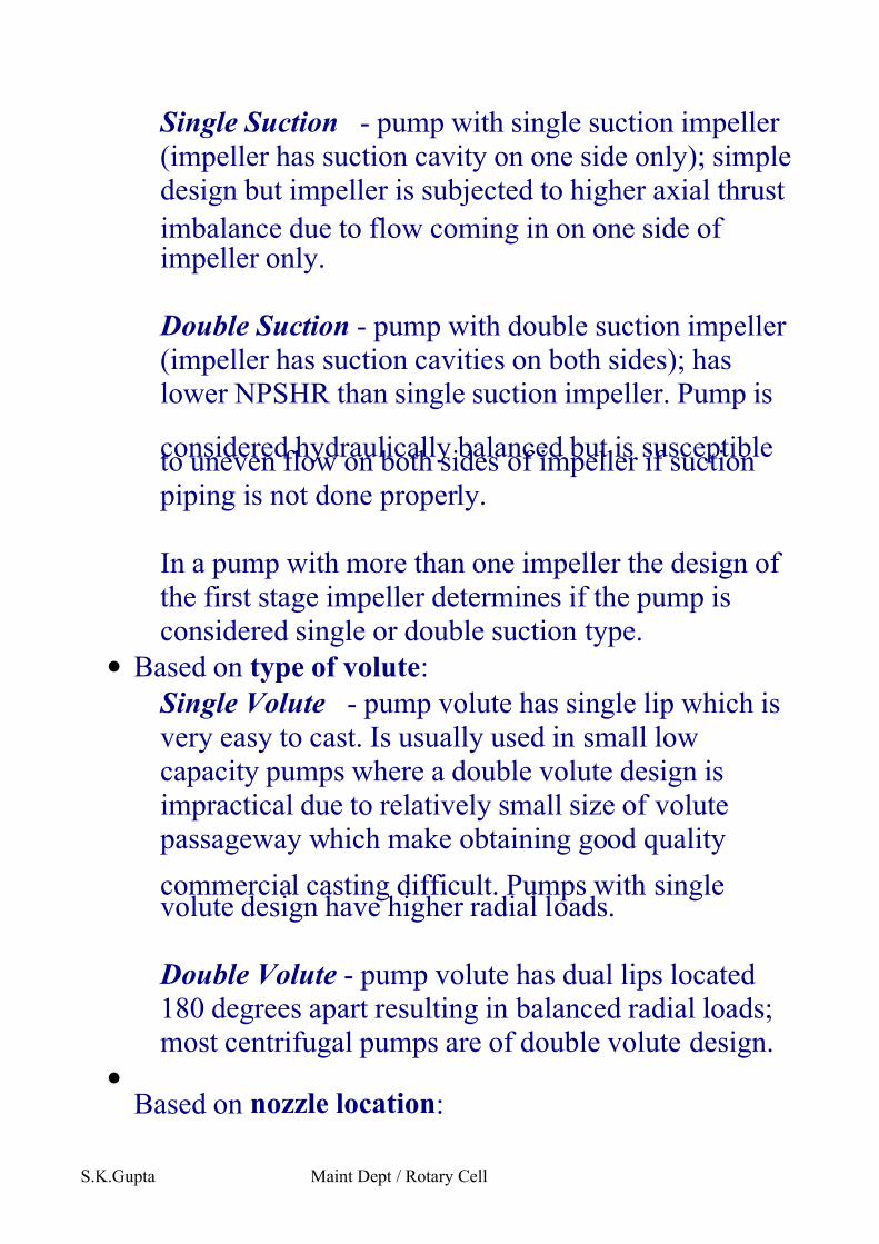
Single Suction - pump with single suction impeller
(impeller has suction cavity on one side only); simple
design but impeller is subjected to higher axial thrust
imbalance due to flow coming in on one side of impeller only.
Double Suction - pump with double suction impeller
(impeller has suction cavities on both sides); has
lower NPSHR than single suction impeller. Pump is
considered hydraulically balanced but is susceptibleto uneven flow on both sides of impeller if suction
piping is not done properly.
In a pump with more than one impeller the design of
the first stage impeller determines if the pump is
considered single or double suction type.
• Based on type of volute:
Single Volute - pump volute has single lip which is
very easy to cast. Is usually used in small low
capacity pumps where a double volute design is
impractical due to relatively small size of volute
passageway which make obtaining good quality
commercial casting difficult. Pumps with singlevolute design have higher radial loads.
Double Volute - pump volute has dual lips located
180 degrees apart resulting in balanced radial loads;
most centrifugal pumps are of double volute design.
•
Based on nozzle location:
S.K.Gupta Maint Dept / Rotary Cell
7/27/2019 PUMP BASICS.doc
http://slidepdf.com/reader/full/pump-basicsdoc 5/12
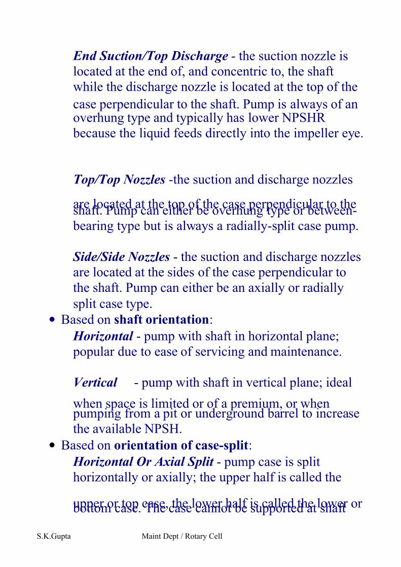
End Suction/Top Discharge - the suction nozzle is
located at the end of, and concentric to, the shaft
while the discharge nozzle is located at the top of the
case perpendicular to the shaft. Pump is always of anoverhung type and typically has lower NPSHR
because the liquid feeds directly into the impeller eye.
Top/Top Nozzles -the suction and discharge nozzles
are located at the top of the case perpendicular to theshaft. Pump can either be overhung type or between-
bearing type but is always a radially-split case pump.
Side/Side Nozzles - the suction and discharge nozzles
are located at the sides of the case perpendicular to
the shaft. Pump can either be an axially or radially
split case type.
• Based on shaft orientation:
Horizontal - pump with shaft in horizontal plane;
popular due to ease of servicing and maintenance.
Vertical - pump with shaft in vertical plane; ideal
when space is limited or of a premium, or when pumping from a pit or underground barrel to increase
the available NPSH.
• Based on orientation of case-split:
Horizontal Or Axial Split - pump case is split
horizontally or axially; the upper half is called the
upper or top case, the lower half is called the lower or bottom case. The case cannot be supported at shaft
S.K.Gupta Maint Dept / Rotary Cell
7/27/2019 PUMP BASICS.doc
http://slidepdf.com/reader/full/pump-basicsdoc 6/12
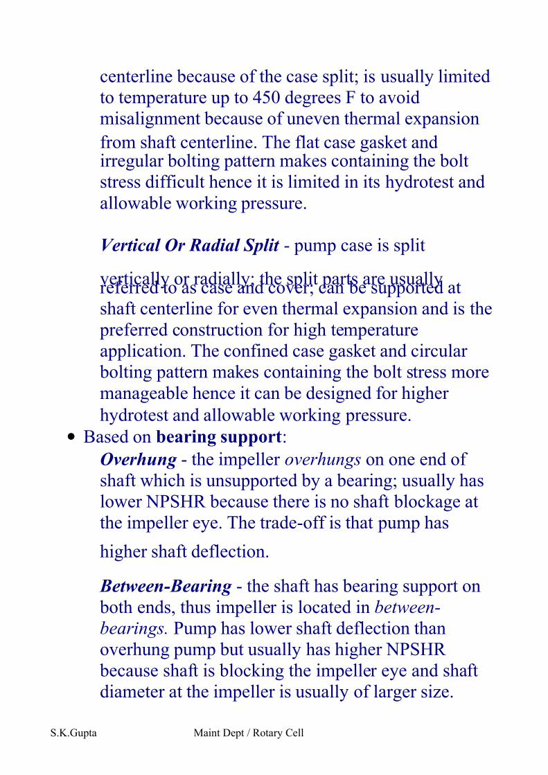
centerline because of the case split; is usually limited
to temperature up to 450 degrees F to avoid
misalignment because of uneven thermal expansion
from shaft centerline. The flat case gasket andirregular bolting pattern makes containing the bolt
stress difficult hence it is limited in its hydrotest and
allowable working pressure.
Vertical Or Radial Split - pump case is split
vertically or radially; the split parts are usuallyreferred to as case and cover; can be supported at
shaft centerline for even thermal expansion and is the
preferred construction for high temperature
application. The confined case gasket and circular
bolting pattern makes containing the bolt stress more
manageable hence it can be designed for higher
hydrotest and allowable working pressure.
• Based on bearing support:
Overhung - the impeller overhungs on one end of
shaft which is unsupported by a bearing; usually has
lower NPSHR because there is no shaft blockage at
the impeller eye. The trade-off is that pump has
higher shaft deflection.
Between-Bearing - the shaft has bearing support on
both ends, thus impeller is located in between-
bearings. Pump has lower shaft deflection than
overhung pump but usually has higher NPSHR
because shaft is blocking the impeller eye and shaft
diameter at the impeller is usually of larger size.
S.K.Gupta Maint Dept / Rotary Cell
7/27/2019 PUMP BASICS.doc
http://slidepdf.com/reader/full/pump-basicsdoc 7/12
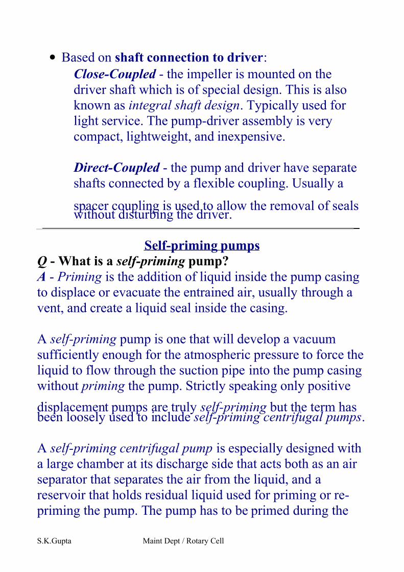
• Based on shaft connection to driver:
Close-Coupled - the impeller is mounted on the
driver shaft which is of special design. This is also
known as integral shaft design. Typically used for
light service. The pump-driver assembly is very
compact, lightweight, and inexpensive.
Direct-Coupled - the pump and driver have separate
shafts connected by a flexible coupling. Usually a
spacer coupling is used to allow the removal of sealswithout disturbing the driver.
Self-priming pumps
Q - What is a self-priming pump?
A - Priming is the addition of liquid inside the pump casing
to displace or evacuate the entrained air, usually through a
vent, and create a liquid seal inside the casing.
A self-priming pump is one that will develop a vacuum
sufficiently enough for the atmospheric pressure to force the
liquid to flow through the suction pipe into the pump casing
without priming the pump. Strictly speaking only positive
displacement pumps are truly self-priming but the term has been loosely used to include self-priming centrifugal pumps.
A self-priming centrifugal pump is especially designed with
a large chamber at its discharge side that acts both as an air
separator that separates the air from the liquid, and a
reservoir that holds residual liquid used for priming or re-
priming the pump. The pump has to be primed during the
S.K.Gupta Maint Dept / Rotary Cell
7/27/2019 PUMP BASICS.doc
http://slidepdf.com/reader/full/pump-basicsdoc 8/12
initial start-up but re-priming is done automatically without
outside attention. Although self-priming appears to be a
desirable feature for centrifugal pumps the trade-off is that
pump efficiency is slightly compromised due to certaindesign constraints. This type of pump is popular with
intermittent service such as in contractors, drainage, sewage,
and similar applications, but is less popular in continuous
service where optimum efficiency is desirable and re-
priming is very seldom needed due to continuous operation.
Specific Speed
Q - What is specific speed ?
A - The old definition of specific speed ( NS ) is simply a
restatement of its equation. It states that NS is the speed in
RPM at which a pump, if sufficiently reduced in size, would
deliver 1 GPM at a head of 1 FT. This definition is
meaningless and has no practical application. In fact, because its equation has inconsistent units, NS is considered
dimensionless.
PumpLine.Com defines NS as a dimensionless number or
index that identifies the geometric similarity of pumps.
Pumps of the same NS but of different size are considered to
be geometrically similar, one pump being a size-factor of
the other.
Specific speed (NS) is calculated from:S.K.Gupta Maint Dept / Rotary Cell
7/27/2019 PUMP BASICS.doc
http://slidepdf.com/reader/full/pump-basicsdoc 9/12
NS = [N x Q^0.50] / [H^0.75]
where:
N = pump speed, RPM
Q = capacity at best efficiency point (BEP) at maximumimpeller diameter, GPM
H = head per stage at BEP at maximum impeller
diameter , FT
Example: What is the specific speed of a two-stage pump
whose capacity and total head at BEP is 400 GPM, and 200
FT, respectively when the pump runs at 1780 RPM?Solution: NS = [1780 x (400)^0.50 / (200/2)^0.75] = 1126
Q - Why is the term specific speed very important?
A - Specific speed has several practical applications:Specific speed identifies the type of pump according to its
design and flow pattern. According to this criteria a pump
can be classified as radial flow, mixed flow, or axial flow
type. A radial flow pump is one where the impeller discharges the liquid in the radial direction from the pump
shaft centerline, an axial flow pump discharges the liquid in
the axial direction and a mixed flow pump is one that is a
cross between a radial and an axial flow pump design.
Specific speed identifies the approximate acceptable ratio of
the impeller eye diameter (D1) to the impeller maximumdiameter (D2) in designing a good impeller.
NS: 500 to 5000; D1/D2 > 1.5 - radial flow pump
NS: 5000 to 10000; D1/D2 < 1.5 - mixed flow pump
NS:10000 to 15000; D1/D2 = 1 - axial flow pump
Specific speed is also used in designing a new pump by size-
factoring a smaller pump of the same specific speed . The
performance and construction of the smaller pump are used
S.K.Gupta Maint Dept / Rotary Cell
7/27/2019 PUMP BASICS.doc
http://slidepdf.com/reader/full/pump-basicsdoc 10/12
to predict the performance and model the construction of the
new pump.
Rule-of-Thumb: For similar pumps with about the same
capacity at BEP, the pump with higher specific speed willtypically have a higher efficiency also.
Suction specific speed
Q - What is suction specific speed ?
A - Suction specific speed (NSS) is a dimensionless number or index that defines the suction characteristics of a pump. It
is calculated from:
NSS = [(N x Q^0.5) / (NPSHR)^0.75]
where:
N = speed, RPM
Q = capacity at BEP, GPM (For double suction impeller,
Q=GPM/2) NPSHR = NPSHR at BEP based on 3% head loss, FT
In multi-stage pump the NPSHR is based on the first stage
impeller NPSHR.
Example: What is the suction specific speed of a double
suction pump operating at 3560 RPM if it required 18 FT of NPSH at its BEP of 800 GPM?
Solution: NSS = [3560 x (800/2)^0.50 / (18)^0.75] = 8148
A practical application of NSS is that it is commonly used as
a basis for estimating the safe operating range of capacity
for a pump. The higher the NSS is, the narrower is its safe
operating range from its BEP. Most users prefer that their
pumps have NSS in the range of 8000 to 11000 for optimum
and trouble-free operation.S.K.Gupta Maint Dept / Rotary Cell
7/27/2019 PUMP BASICS.doc
http://slidepdf.com/reader/full/pump-basicsdoc 11/12
Best efficiency point
Q - What is referred to as Best Efficiency Point ?
A - Best Efficiency Point (BEP) is the capacity at themaximum impeller diameter performance curve at which the
efficiency is highest. BEP is an important parameter in that
many parametric calculations such as specific speed, suction
specific speed, hydrodynamic size, viscosity correction,
headrise to shut-off, etc. are based on the capacity at BEP.
Many users prefer that pumps operate within 80% to 110%of its BEP for optimum performance.
Affinity Laws
Q - What are the Affinity Laws?
A - The Affinity Laws refer to the mathematical expressions
that define the changes in pump capacity, head, and required
BHP when a change is made to pump speed, impeller diameter, or both. According to Affinity Laws:
The capacity (Q) changes in direct proportion to the
impeller diameter (D) ratio, or to the speed (N) ratio:
Q2 = Q1 x [D2/D1]
Q2 = Q1 x [N2/N1]The head (H) changes in direct proportion to the square
of impeller diameter (D) ratio, or to the square of the
speed (N) ratio:
H2 = H1 x [D2/D1]^2
H2 = H1 x [N2/N1]^2
The BHP changes in direct proportion to the cube of
impeller diameter ratio, or to the cube of the speed
ratio:S.K.Gupta Maint Dept / Rotary Cell
7/27/2019 PUMP BASICS.doc
http://slidepdf.com/reader/full/pump-basicsdoc 12/12
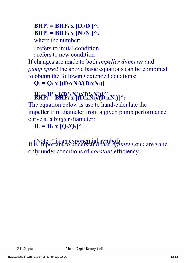
BHP2 = BHP1 x [D2/D1]^3
BHP2 = BHP1 x [N2/N1]^3
where the number:
1 refers to initial condition2 refers to new condition
If changes are made to both impeller diameter and
pump speed the above basic equations can be combined
to obtain the following extended equations:
Q2 = Q1 x [(D2xN2)/(D1xN1)]
H2 = H1 x [(D2xN2)/(D1xN1)]^2
BHP2 = BHP1 x [(D2xN2)/(D1xN1)]^3
The equation below is use to hand-calculate the
impeller trim diameter from a given pump performance
curve at a bigger diameter:
H2 = H1 x [Q2/Q1]^2
(Note: ^ is an exponential symbol)It is important to understand that Affinity Laws are valid
only under conditions of constant efficiency.
S.K.Gupta Maint Dept / Rotary Cell