Embed Size (px)
Citation preview
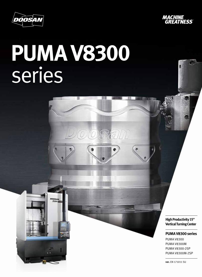
PUMA V8300 series
PUMA V8300 seriesPUMA V8300PUMA V8300MPUMA V8300-2SPPUMA V8300M-2SP
High Productivity 15" Vertical Turning Center
ver. EN 171011 SU
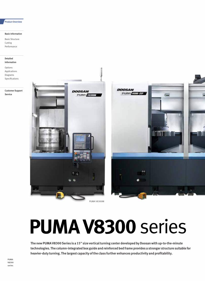
PUMA V8300M
The new PUMA V8300 Series is a 15" size vertical turning center developed by Doosan with up-to-the-minute
technologies. The column-integrated box guide and reinforced bed frame provides a stronger structure suitable for
heavier-duty turning. The largest capacity of the class further enhances productivity and profitability.
PUMA V8300 series
0302 /
PUMA
V8300
series
Product Overview
Basic Information
Basic Structure
Cutting
Performance
Detailed
Information
Options
Applications
Diagrams
Specifications
Customer Support
Service
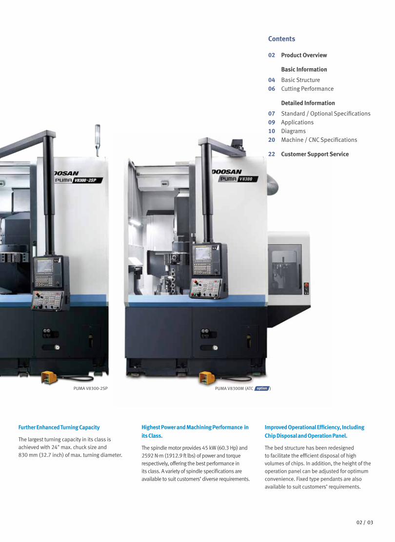
PUMA V8300-2SP PUMA V8300M (ATC )
Further Enhanced Turning Capacity
The largest turning capacity in its class is achieved with 24" max. chuck size and 830 mm (32.7 inch) of max. turning diameter.
Highest Power and Machining Performance in
its Class.
The spindle motor provides 45 kW (60.3 Hp) and 2592 N.m (1912.9 ft lbs) of power and torque respectively, offering the best performance in its class. A variety of spindle specifications are available to suit customers’ diverse requirements.
Improved Operational Efficiency, Including
Chip Disposal and Operation Panel.
The bed structure has been redesigned to facilitate the efficient disposal of high volumes of chips. In addition, the height of the operation panel can be adjusted for optimum convenience. Fixed type pendants are also available to suit customers’ requirements.
Contents
02 Product Overview
Basic Information
04 Basic Structure
06 Cutting Performance
Detailed Information
07 Standard / Optional Specifications
09 Applications
10 Diagrams
20 Machine / CNC Specifications
22 Customer Support Service
0302 /
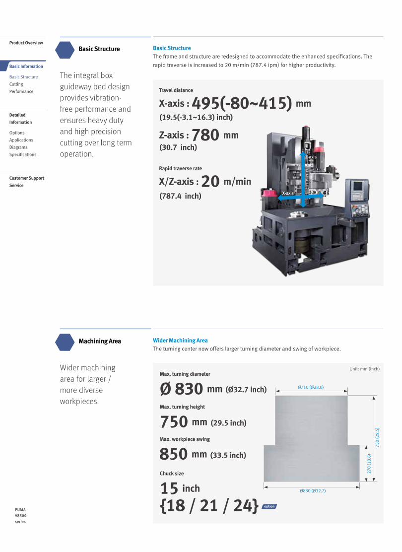
The integral box guideway bed design provides vibration-free performance and ensures heavy duty and high precision cutting over long term operation.
Basic Structure Basic Structure The frame and structure are redesigned to accommodate the enhanced specifications. The
rapid traverse is increased to 20 m/min (787.4 ipm) for higher productivity.
Wider Machining Area The turning center now offers larger turning diameter and swing of workpiece.
Wider machining area for larger / more diverse workpieces.
Machining Area
(19.5(-3.1~16.3) inch)
(30.7 inch)
(787.4 inch)
Travel distance
X-axis : 495(-80~415) mm
Z-axis : 780 mm
Rapid traverse rate
X/Z-axis : 20 m/min X-axis
Z-axis
Max. turning diameter
Ø 830 mm
Max. workpiece swing
850 mm
(Ø32.7 inch)
Max. turning height
750 mm (29.5 inch)
(33.5 inch)
Unit: mm (inch)27
0 (1
0 .6 )
Ø710 (Ø28.0)
Ø830 (Ø32.7)
750
(29 .
5 )
0504 /
PUMA
V8300
series
Product Overview
Basic Information
Basic Structure
Cutting
Performance
Detailed
Information
Options
Applications
Diagrams
Specifications
Customer Support
Service
Chuck size
15 inch
{18 / 21 / 24}
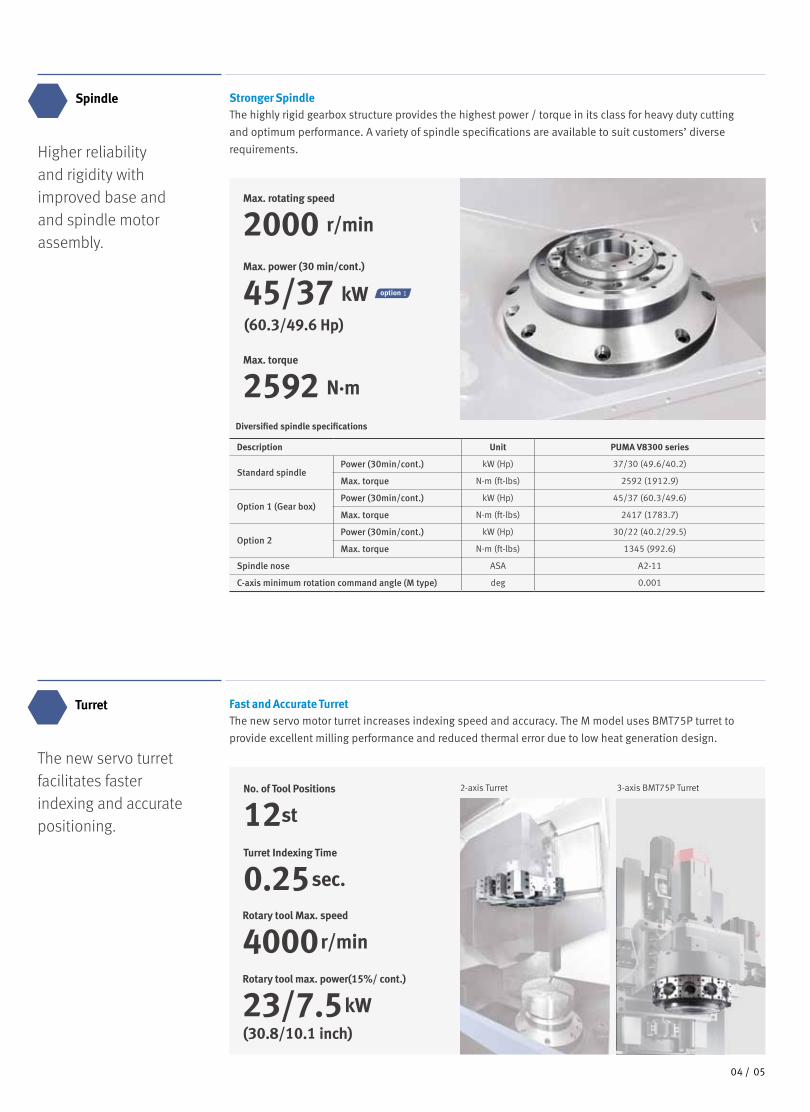
Fast and Accurate Turret The new servo motor turret increases indexing speed and accuracy. The M model uses BMT75P turret to
provide excellent milling performance and reduced thermal error due to low heat generation design.
Higher reliability and rigidity with improved base and and spindle motor assembly.
Stronger Spindle The highly rigid gearbox structure provides the highest power / torque in its class for heavy duty cutting
and optimum performance. A variety of spindle specifications are available to suit customers’ diverse
requirements.
Max. rotating speed
2000 r/min
Max. power (30 min/cont.)
45/37 kW
Max. torque
2592 N.m
Spindle
The new servo turret facilitates faster indexing and accurate positioning.
Turret
Description Unit PUMA V8300 series
Standard spindlePower (30min/cont.) kW (Hp) 37/30 (49.6/40.2)
Max. torque N·m (ft-lbs) 2592 (1912.9)
Option 1 (Gear box)Power (30min/cont.) kW (Hp) 45/37 (60.3/49.6)
Max. torque N·m (ft-lbs) 2417 (1783.7)
Option 2Power (30min/cont.) kW (Hp) 30/22 (40.2/29.5)
Max. torque N·m (ft-lbs) 1345 (992.6)
Spindle nose ASA A2-11
C-axis minimum rotation command angle (M type) deg 0.001
Diversified spindle specifications
(60.3/49.6 Hp)
Turret Indexing Time
0.25 sec.
Rotary tool Max. speed
4000 r/min
Rotary tool max. power(15%/ cont.)
23/7.5 kW
No. of Tool Positions
12st
3-axis BMT75P Turret2-axis Turret
(30.8/10.1 inch)
0504 /
1
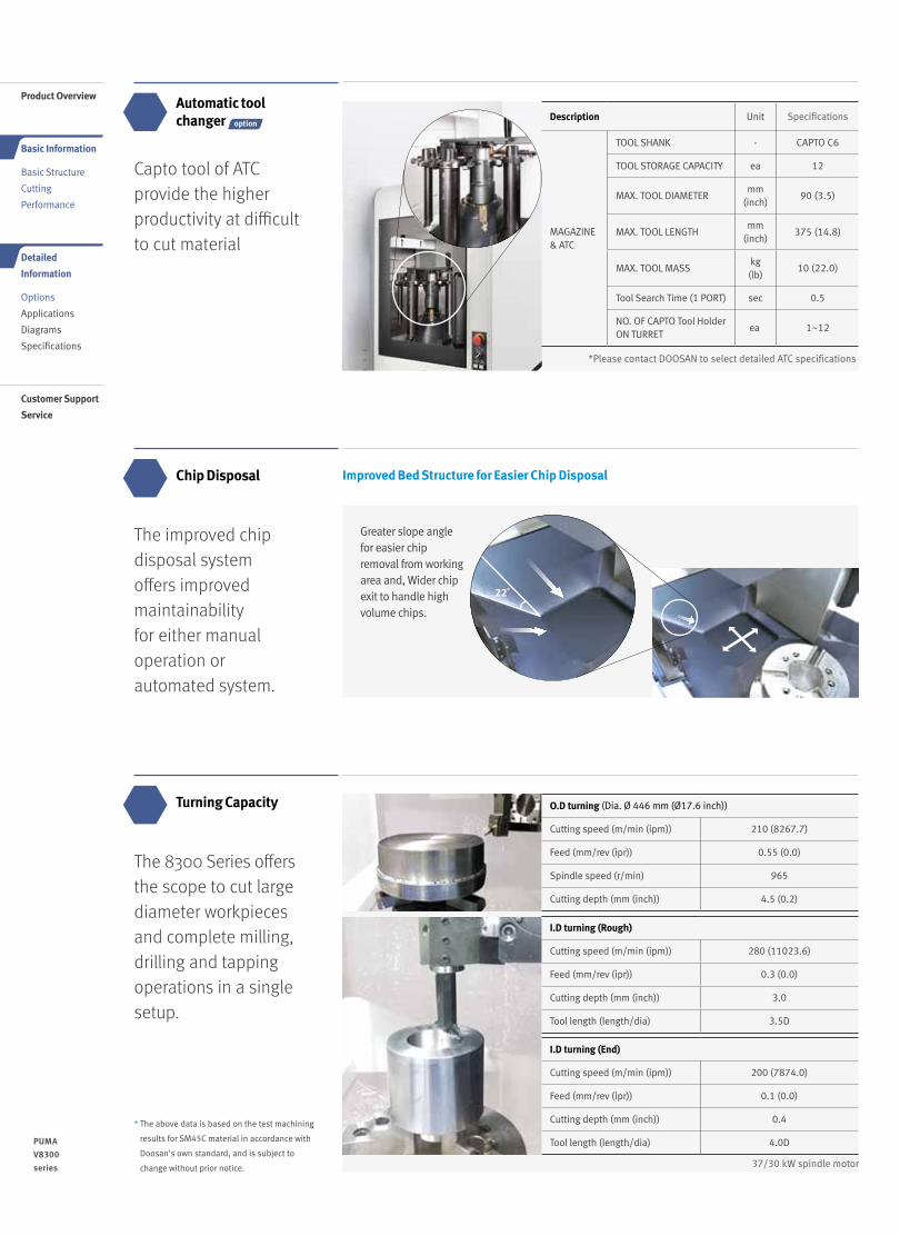
The 8300 Series offers the scope to cut large diameter workpieces and complete milling, drilling and tapping operations in a single setup.
Turning Capacity
37/30 kW spindle motor
I.D turning (Rough)
Cutting speed (m/min (ipm)) 280 (11023.6)
Feed (mm/rev (ipr)) 0.3 (0.0)
Cutting depth (mm (inch)) 3.0
Tool length (length/dia) 3.5D
I.D turning (End)
Cutting speed (m/min (ipm)) 200 (7874.0)
Feed (mm/rev (ipr)) 0.1 (0.0)
Cutting depth (mm (inch)) 0.4
Tool length (length/dia) 4.0D
O.D turning (Dia. Ø 446 mm (Ø17.6 inch))
Cutting speed (m/min (ipm)) 210 (8267.7)
Feed (mm/rev (ipr)) 0.55 (0.0)
Spindle speed (r/min) 965
Cutting depth (mm (inch)) 4.5 (0.2)
Automatic tool changer
* The above data is based on the test machining
results for SM45C material in accordance with
Doosan's own standard, and is subject to
change without prior notice.
The improved chip disposal system offers improved maintainability for either manual operation or automated system.
Chip Disposal Improved Bed Structure for Easier Chip Disposal
22˚
Greater slope angle for easier chip removal from working area and, Wider chip exit to handle high volume chips.
Capto tool of ATC provide the higher productivity at difficult to cut material
Description Unit Specifications
MAGAZINE & ATC
TOOL SHANK - CAPTO C6
TOOL STORAGE CAPACITY ea 12
MAX. TOOL DIAMETERmm
(inch)90 (3.5)
MAX. TOOL LENGTHmm
(inch)375 (14.8)
MAX. TOOL MASSkg(lb)
10 (22.0)
Tool Search Time (1 PORT) sec 0.5
NO. OF CAPTO Tool Holder ON TURRET
ea 1~12
*Please contact DOOSAN to select detailed ATC specifications
0706 /
PUMA
V8300
series
Product Overview
Basic Information
Basic Structure
Cutting
Performance
Detailed
Information
Options
Applications
Diagrams
Specifications
Customer Support
Service
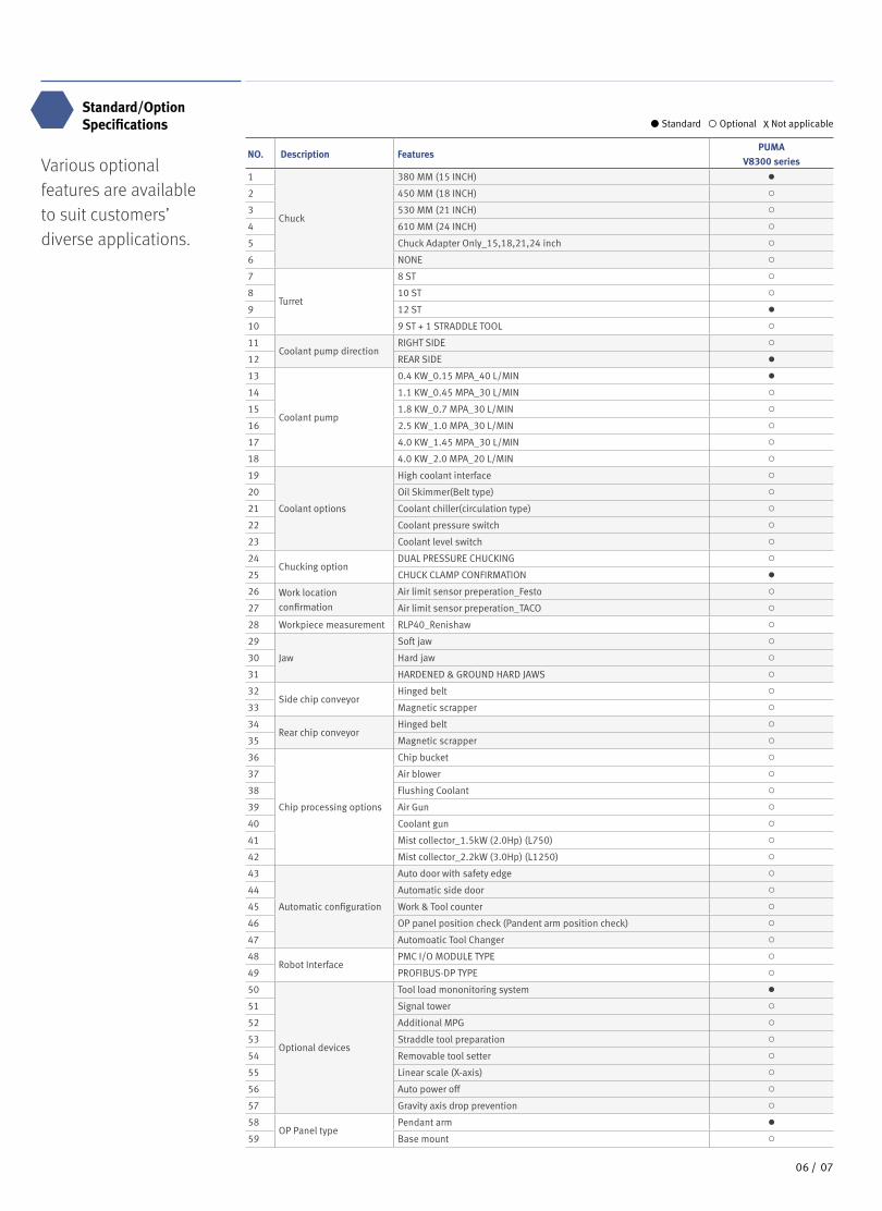
Standard/Option Specifications
Various optional features are available to suit customers’ diverse applications.
NO. Description FeaturesPUMA
V8300 series
1
Chuck
380 MM (15 INCH) ●
2 450 MM (18 INCH) ○
3 530 MM (21 INCH) ○
4 610 MM (24 INCH) ○
5 Chuck Adapter Only_15,18,21,24 inch ○
6 NONE ○
7
Turret
8 ST ○
8 10 ST ○
9 12 ST ●
10 9 ST + 1 STRADDLE TOOL ○
11Coolant pump direction
RIGHT SIDE ○
12 REAR SIDE ●
13
Coolant pump
0.4 KW_0.15 MPA_40 L/MIN ●
14 1.1 KW_0.45 MPA_30 L/MIN ○
15 1.8 KW_0.7 MPA_30 L/MIN ○
16 2.5 KW_1.0 MPA_30 L/MIN ○
17 4.0 KW_1.45 MPA_30 L/MIN ○
18 4.0 KW_2.0 MPA_20 L/MIN ○
19
Coolant options
High coolant interface ○
20 Oil Skimmer(Belt type) ○
21 Coolant chiller(circulation type) ○
22 Coolant pressure switch ○
23 Coolant level switch ○
24Chucking option
DUAL PRESSURE CHUCKING ○
25 CHUCK CLAMP CONFIRMATION ●
26 Work location
confirmation
Air limit sensor preperation_Festo ○
27 Air limit sensor preperation_TACO ○
28 Workpiece measurement RLP40_Renishaw ○
29
Jaw
Soft jaw ○
30 Hard jaw ○
31 HARDENED & GROUND HARD JAWS ○
32Side chip conveyor
Hinged belt ○
33 Magnetic scrapper ○
34Rear chip conveyor
Hinged belt ○
35 Magnetic scrapper ○
36
Chip processing options
Chip bucket ○
37 Air blower ○
38 Flushing Coolant ○
39 Air Gun ○
40 Coolant gun ○
41 Mist collector_1.5kW (2.0Hp) (L750) ○
42 Mist collector_2.2kW (3.0Hp) (L1250) ○
43
Automatic configuration
Auto door with safety edge ○
44 Automatic side door ○
45 Work & Tool counter ○
46 OP panel position check (Pandent arm position check) ○
47 Automoatic Tool Changer ○
48Robot Interface
PMC I/O MODULE TYPE ○
49 PROFIBUS-DP TYPE ○
50
Optional devices
Tool load mononitoring system ●
51 Signal tower ○
52 Additional MPG ○
53 Straddle tool preparation ○
54 Removable tool setter ○
55 Linear scale (X-axis) ○
56 Auto power off ○
57 Gravity axis drop prevention ○
58OP Panel type
Pendant arm ●
59 Base mount ○
Standard Optional X Not applicable
0706 /
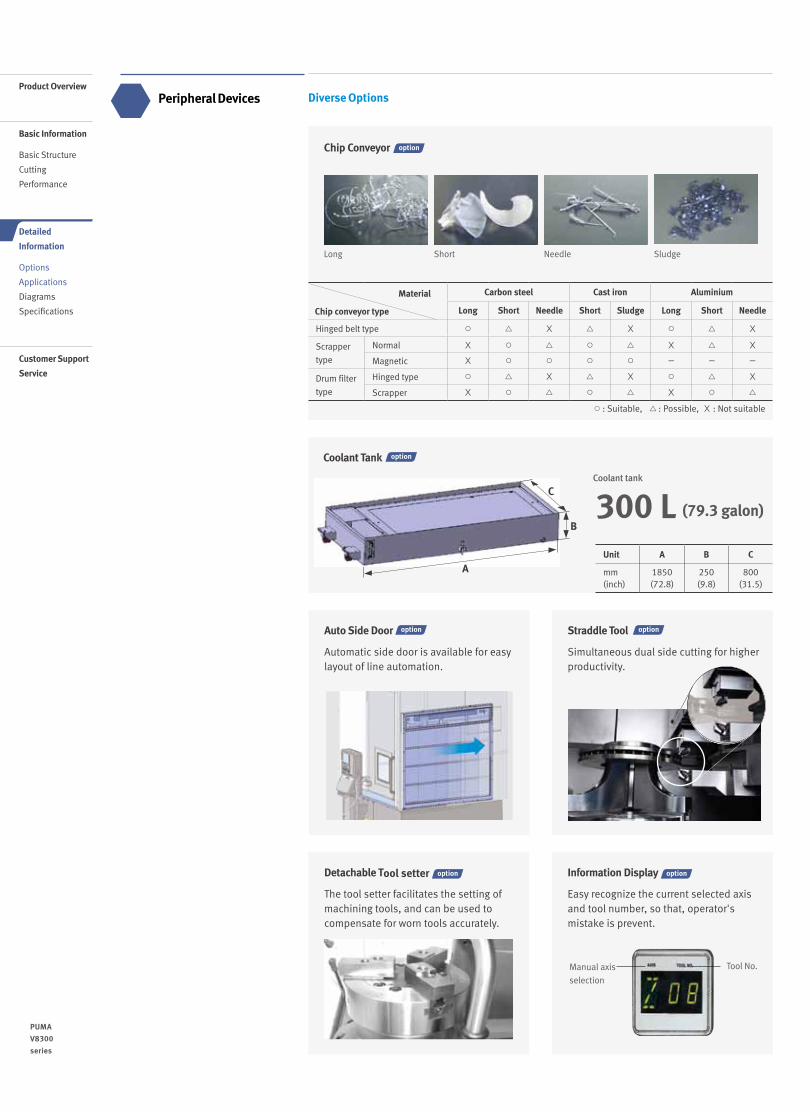
Diverse Options
0908 /
PUMA
V8300
series
Peripheral Devices
Auto Side Door
Automatic side door is available for easy layout of line automation.
Straddle Tool
Simultaneous dual side cutting for higher productivity.
B
C
Unit A B C
mm(inch)
1850(72.8)
250(9.8)
800(31.5)
300 L (79.3 galon)
Coolant tank
Coolant Tank
A
Product Overview
Basic Information
Basic Structure
Cutting
Performance
Detailed
Information
Options
Applications
Diagrams
Specifications
Customer Support
Service
Detachable Tool setter
The tool setter facilitates the setting of machining tools, and can be used to compensate for worn tools accurately.
Information Display
Easy recognize the current selected axis and tool number, so that, operator's mistake is prevent.
Manual axis
selection
Tool No.
Chip Conveyor
○ : Suitable, △ : Possible, X : Not suitable
Material
Chip conveyor type
Carbon steel Cast iron Aluminium
Long Short Needle Short Sludge Long Short Needle
Hinged belt type ○ △ X △ X ○ △ X
Scrapper
type
Normal X ○ △ ○ △ X △ X
Magnetic X ○ ○ ○ ○ - - -
Drum filter
type
Hinged type ○ △ X △ X ○ △ X
Scrapper X ○ △ ○ △ X ○ △
Long Short Needle Sludge
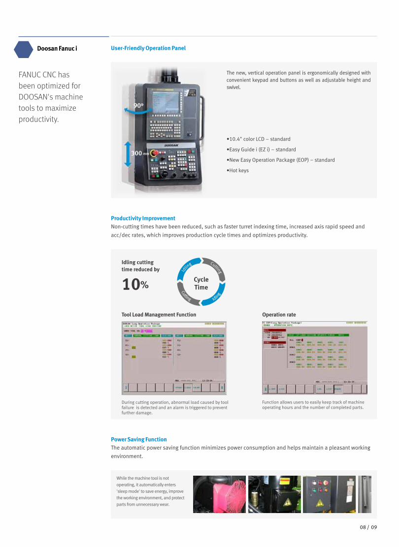
FANUC CNC has been optimized for DOOSAN's machine tools to maximize productivity.
Doosan Fanuc i User-Friendly Operation Panel
•10.4" color LCD – standard
•Easy Guide i (EZ i) – standard
•New Easy Operation Package (EOP) – standard
•Hot keys
The new, vertical operation panel is ergonomically designed with convenient keypad and buttons as well as adjustable height and swivel.
Productivity Improvement Non-cutting times have been reduced, such as faster turret indexing time, increased axis rapid speed and
acc/dec rates, which improves production cycle times and optimizes productivity.
Idling cutting time reduced by
10% Cycle Time
Idlin
g
Idling
Cutting
Cutting
Power Saving FunctionThe automatic power saving function minimizes power consumption and helps maintain a pleasant working
environment.
While the machine tool is not
operating, it automatically enters
'sleep mode' to save energy, improve
the working environment, and protect
parts from unnecessary wear.
Tool Load Management Function
During cutting operation, abnormal load caused by tool failure is detected and an alarm is triggered to prevent further damage.
Operation rate
Function allows users to easily keep track of machine operating hours and the number of completed parts.
0908 /
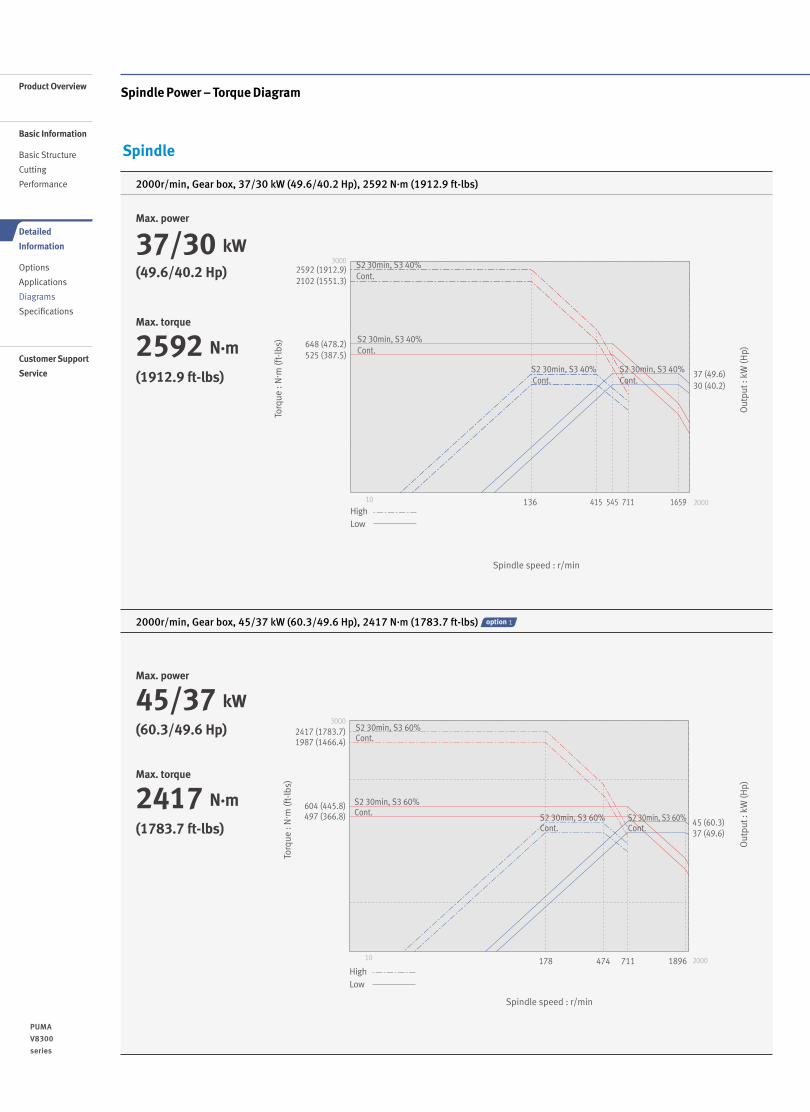
2000r/min, Gear box, 37/30 kW (49.6/40.2 Hp), 2592 N.m (1912.9 ft-lbs)
2000r/min, Gear box, 45/37 kW (60.3/49.6 Hp), 2417 N.m (1783.7 ft-lbs) 1
Spindle
Spindle Power – Torque Diagram
Max. power
37/30 kW(49.6/40.2 Hp)
(1912.9 ft-lbs)
Max. torque
2592 N·m
Out
put :
kW
(Hp)
Torq
ue :
N. m
(ft-
lbs)
Spindle speed : r/min
Max. power
45/37 kW
100 1000 4000
300
10
10
Cont.
S2 30min, S3 60%
S2 30min, S3 60%
S3 25%
S3 25%
48 (35.4)
70 (51.7)
95 (70.1)
S3 15%
7.5 (10.1)
11 (14.8)
15 (20.1)
23 (30.8)
1500 2000
S3 15%146 (107.7)
HighLow
Cont.
3000
Cont.
Cont.497 (366.8) S2 30min, S3 60%
37 (49.6)45 (60.3)
1896
S2 30min, S3 60%604 (445.8)S2 30min, S3 60%
S2 30min, S3 60%2417 (1783.7)1987 (1466.4)
Cont.
178 474 711
Cont.
200010
HighLow
(60.3/49.6 Hp)
(1783.7 ft-lbs)
Max. torque
2417 N·m
Out
put :
kW
(Hp)
Torq
ue :
N. m
(ft-
lbs)
Spindle speed : r/min
2000
648 (478.2)525 (387.5)
30002592 (1912.9)2102 (1551.3)
545 1659415
S2 30min, S3 40%
136 711
Cont.
Cont.
Cont.
S2 30min, S3 40%
S2 30min, S3 40%
S2 30min, S3 40% 37 (49.6)Cont. 30 (40.2)
10
HighLow
10 2000
3000
Cont.
S2 30min, S3 25%
S2 30min, S3 25%
Cont. 22 (29.5)
1481
473 (349.1)
S2 30min, S3 60% 30 (40.2)
444213 556 1111
S2 30min, S3 60%645 (476.0)
1345 (992.6)
986 (727.7) Cont.
Cont.
HighLow
1110 /
PUMA
V8300
series
Product Overview
Basic Information
Basic Structure
Cutting
Performance
Detailed
Information
Options
Applications
Diagrams
Specifications
Customer Support
Service
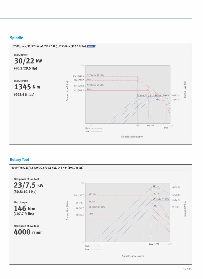
4000r/min, 23/7.5 kW (30.8/10.1 Hp), 146 N.m (107.7 ft-lbs)
2000r/min, 30/22 kW (40.2/29.5 Hp), 1345 N.m (992.6 ft-lbs) 2
Spindle
Rotary Tool
Out
put :
kW
(Hp)
Out
put :
kW
(Hp)
Torq
ue :
N. m
(ft-
lbs)
Torq
ue :
N. m
(ft-
lbs)
Spindle speed : r/min
Spindle speed : r/min
2000
648 (478.2)525 (387.5)
30002592 (1912.9)2102 (1551.3)
545 1659415
S2 30min, S3 40%
136 711
Cont.
Cont.
Cont.
S2 30min, S3 40%
S2 30min, S3 40%
S2 30min, S3 40% 37 (49.6)Cont. 30 (40.2)
10
HighLow
10 2000
3000
Cont.
S2 30min, S3 25%
S2 30min, S3 25%
Cont. 22 (29.5)
1481
473 (349.1)
S2 30min, S3 60% 30 (40.2)
444213 556 1111
S2 30min, S3 60%645 (476.0)
1345 (992.6)
986 (727.7) Cont.
Cont.
HighLow
Max. power
30/22 kW
Max power of live tool
23/7.5 kW
100 1000 4000
300
10
10
Cont.
S2 30min, S3 60%
S2 30min, S3 60%
S3 25%
S3 25%
48 (35.4)
70 (51.7)
95 (70.1)
S3 15%
7.5 (10.1)
11 (14.8)
15 (20.1)
23 (30.8)
1500 2000
S3 15%146 (107.7)
HighLow
Cont.
3000
Cont.
Cont.497 (366.8) S2 30min, S3 60%
37 (49.6)45 (60.3)
1896
S2 30min, S3 60%604 (445.8)S2 30min, S3 60%
S2 30min, S3 60%2417 (1783.7)1987 (1466.4)
Cont.
178 474 711
Cont.
200010
HighLow
(40.2/29.5 Hp)
(30.8/10.1 Hp)
(992.6 ft-lbs)
(107.7 ft-lbs)
Max. torque
1345 N·m
Max. torque
146 N·m
Max speed of live tool
4000 r/min
1110 /
1312 /
PUMA
V8300
series
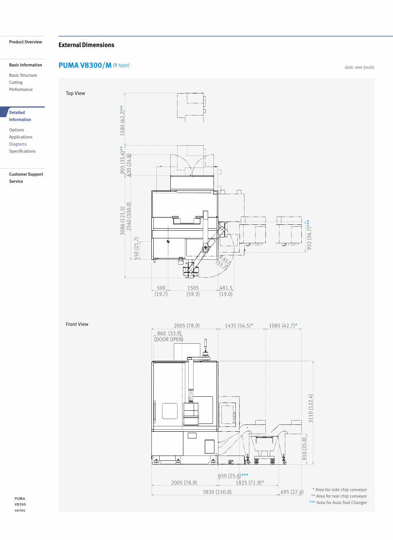
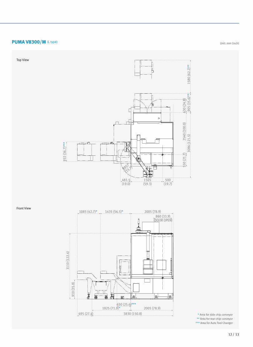
PUMA V8300/M (R type)
Front View
Top View
Unit: mm (inch)
External DimensionsProduct Overview
Basic Information
Basic Structure
Cutting
Performance
Detailed
Information
Options
Applications
Diagrams
Specifications
Customer Support
Service
* Area for side chip conveyor
** Area for rear chip conveyor
*** Area for Auto Tool Changer
500(19.7)
2005 (78.9) 1435 (56.5)* 1085 (42.7)* 860 (33.9)
(DOOR OPEN)
2005 (78.9)650 (25.6)***
1825 (71.9)*
910
(35.
8)31
10 (1
22.4
)
3830 (150.8) 695 (27.4)
1505(59.3)
3086
(121
.5)
2540
(100
.0)
550
(21.
7)
932
(36.
7)**
*
630
(24.
8)90
5 (3
5.6)
**15
80 (6
2.2)
**
481.5(19.0)
R 857(33.7)
1312 /
PUMA V8300/M (L type)
Front View
Top View
Unit: mm (inch)
* Area for side chip conveyor
** Area for rear chip conveyor
*** Area for Auto Tool Changer
1505(59.3)
481.5(19.0)
R857
(33.7)
500(19.7)
2005 (78.9)1435 (56.5)*1085 (42.7)*860 (33.9)
(DOOR OPEN)
550
(21.
7)25
40 (1
00.0
)
932
(36.
7)**
*
630
(24.
8)90
5 (3
5.6)
**30
86 (1
21.5
)
1825 (71.9)*650 (25.6)***
3110
(122
.4)
910
(35.
8)
2005 (78.9)
3830 (150.8)695 (27.4)
1580
(62.
2)**
1514 /
PUMA
V8300
series
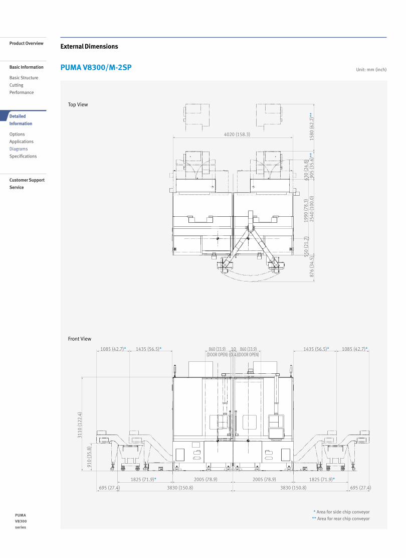
PUMA V8300/M-2SP
Front View
Unit: mm (inch)
External DimensionsProduct Overview
Basic Information
Basic Structure
Cutting
Performance
Detailed
Information
Options
Applications
Diagrams
Specifications
Customer Support
Service
Top View
4020 (158.3)
630
(24.
8)19
90 (7
8.3)
2540
(100
.0)
905
(35.
6)**
1580
(62.
2)**
876
(34.
5)
860 (33.9)(DOOR OPEN)
1435 (56.5)*1085 (42.7)* 1435 (56.5)* 1085 (42.7)*860 (33.9)(DOOR OPEN)
10(0.4)
550
(21.
7)
1825 (71.9)* 1825 (71.9)*2005 (78.9) 2005 (78.9)
3830 (150.8) 3830 (150.8) 695 (27.4)695 (27.4)
3110
(122
.4)
910
(35.
8)
* Area for side chip conveyor
** Area for rear chip conveyor
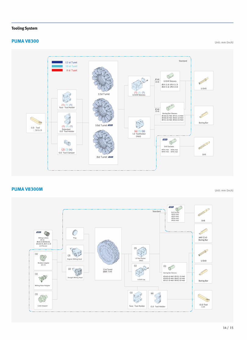
Tooling System
PUMA V8300
PUMA V8300M
Unit: mm (inch)
Unit: mm (inch)
10st Turret
12st Turret선택
8st Turret
10 st Turet
12 st Turet
8 st Turet
Standard
Face Tool Holder
ExtendedO.D Tool Holder
O.D Tool Clamper
U-Drill Sleeves
I.D ToolHolder (H60)
Ø 60U-Drill Sleeves
60
Ø16(0.6)-H60 Ø32(1.3)-H60Ø20(0.8)-H60 Ø40(1.6)-H60Ø25(1.0)-H60 Ø50(2.0)-H60
Boring Bar Sleeves
U-Drill
Boring Bar
Drill
MT#2-H60MT#3-H60
MT#4-H60MT#5-H60
Drill Sockets
(2) (3) (4)
(4) (5) (6)32O.D Tool
Ø25 (1.0) Ø32 (1.3)Ø40 (1.6) Ø50 (2.0)
(2.4)
(1.3)
(2.4)Ø
(1) (4)
(1)
(1)
(1)
(2)
(2)
(3)
(1) (1)
Plug
Angular Milling Head
Straight Milling Head
I.D Tool Holder(H60)
U-Drill Cap
U-Drill
Drill
Boring Bar
Boring Bar Sleeves
Drill SocketMT#2-H60MT#3-H60MT#4-H60
12st Turret(BMT 75P)
25
MT#5-H60
Milling Collets ER 40
(19 Pieces)
Weldon Adapter(ID 25)
Milling Arbor Adapter
Collet Adapter Face Tool Holder O.D Tool Holder
선
Standard
선
Ø16(0.6)-H60 Ø32(1.3)-H60Ø20(0.8)-H60 Ø40(1.6)-H60Ø25(1.0)-H60 Ø50(2.0)-H60
Ø4(0.2)-Ø20(0.8), Ø22(0.9), Ø25 (1.0)
Ø60 (2.4) Boring Bar
1514 /
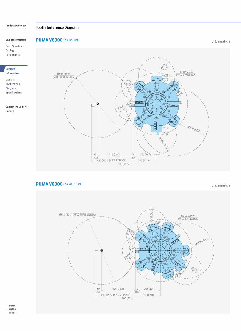
Tool Interference Diagram
Unit: mm (inch)
Unit: mm (inch)
PUMA V8300 (2-axis, 8st)
PUMA V8300 (2-axis, 10st)
40 (1.6)
Ø830 (32.7) (MAX. TURNING DIA.)
800 (31.5) 495 (19.5) (X AXIS TRAVEL)
64 (2.5
)
72 (2.8)
50
(2.0)
75 (3.0
)40 (1.6
) 8 (0.3)
80 (3.1)
415 (16.3) 265 (10.4)
305 (12.0)
Ø414(16.3)
Ø414
(16.3)
Ø447(1
7.6)
Ø760 (29.9)(MAX. SWING DIA.)
Ø830 (32.7)
Ø484 (19.1)
Ø60
40 (1.6)
Ø830 (32.7) (MAX. TURNING DIA.)
495 (19.5) (X AXIS TRAVEL)800 (31.5)
305 (12.0)
265 (10.4)415 (16.3) 80 (3.1)
Ø569
(22.
4)
Ø760 (29.9) (MAX. SWING DIA.)
64 (2.5
)
50 (2.0
)72(2.8)8(0.3)
Ø28
6 (1
1.3)
Ø60 (2.4)
75(3.0) 40(1.6)
Ø258 (10.2)
Ø261(10.3)
Ø320 (12.6)
Ø760 (29.9) (MAX. SWING DIA.)
Ø830 (32.7) (MAX. TURNING DIA.)
800 (31.5) 495 (19.5) (X AXIS TRAVEL)
64 (2.5
)
72(2.8)8(0.3)
50(2.0)
80 (3.1)
40 (1.6)
415 (16.3) 265 (10.4)
305 (12.0)
Ø35
1 (1
3.8)
Ø680 (26.8)
Ø386(15.2)
Ø321(12.6)
Ø323
(12.7)
Ø60(2.4)
75(3.0) 40(1.6)
Ø830 (32.7) (MAX. TURNING DIA.)
800 (31.5) 495 (19.5) (X AXIS TRAVEL)
50(2.
0)
50(2.
0)
60 (2.4
)
80 (3.1)
40 (1.6)
50 (2.0)
415 (16.3) 215 (8.5)
305 (12.0)
Ø258 (10.2)
Ø224 (8.8)
Ø222 (8.7)
Ø245
(9.6
)
Ø279 (11.0)
Ø748 (29.4) (MAX. SWING DIA.)
74(2.9)
60(2.4)
85(3.3)
Ø26 (1.0) Ø69 (2.7)
Ø60(2.4)
7 (0.3
)
1716 /
PUMA
V8300
series
Product Overview
Basic Information
Basic Structure
Cutting
Performance
Detailed
Information
Options
Applications
Diagrams
Specifications
Customer Support
Service
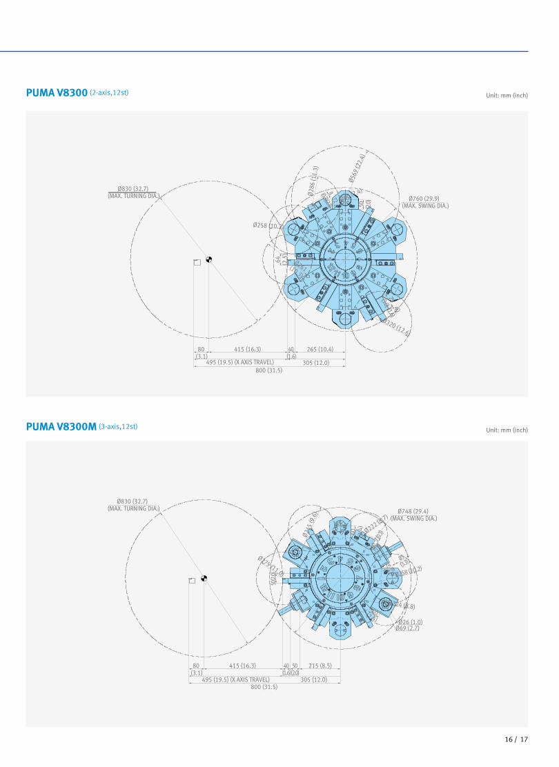
Unit: mm (inch)
Unit: mm (inch)
PUMA V8300 (2-axis,12st)
PUMA V8300M (3-axis,12st)
40 (1.6)
Ø830 (32.7) (MAX. TURNING DIA.)
800 (31.5) 495 (19.5) (X AXIS TRAVEL)
64 (2.5
)
72 (2.8)
50
(2.0)
75 (3.0
)40 (1.6
) 8 (0.3)
80 (3.1)
415 (16.3) 265 (10.4)
305 (12.0)
Ø414(16.3)
Ø414
(16.3)
Ø447(1
7.6)
Ø760 (29.9)(MAX. SWING DIA.)
Ø830 (32.7)
Ø484 (19.1)
Ø60
40 (1.6)
Ø830 (32.7) (MAX. TURNING DIA.)
495 (19.5) (X AXIS TRAVEL)800 (31.5)
305 (12.0)
265 (10.4)415 (16.3) 80 (3.1)
Ø569
(22.
4)
Ø760 (29.9) (MAX. SWING DIA.)
64 (2.5
)
50 (2.0
)72(2.8)8(0.3)
Ø28
6 (1
1.3)
Ø60 (2.4)
75(3.0) 40(1.6)
Ø258 (10.2)
Ø261(10.3)
Ø320 (12.6)
Ø760 (29.9) (MAX. SWING DIA.)
Ø830 (32.7) (MAX. TURNING DIA.)
800 (31.5) 495 (19.5) (X AXIS TRAVEL)
64 (2.5
)
72(2.8)8(0.3)
50(2.0)
80 (3.1)
40 (1.6)
415 (16.3) 265 (10.4)
305 (12.0)
Ø35
1 (1
3.8)
Ø680 (26.8)
Ø386(15.2)
Ø321(12.6)
Ø323
(12.7)
Ø60(2.4)
75(3.0) 40(1.6)
Ø830 (32.7) (MAX. TURNING DIA.)
800 (31.5) 495 (19.5) (X AXIS TRAVEL)
50(2.
0)
50(2.
0)
60 (2.4
)
80 (3.1)
40 (1.6)
50 (2.0)
415 (16.3) 215 (8.5)
305 (12.0)
Ø258 (10.2)
Ø224 (8.8)
Ø222 (8.7)
Ø245
(9.6
)
Ø279 (11.0)
Ø748 (29.4) (MAX. SWING DIA.)
74(2.9)
60(2.4)
85(3.3)
Ø26 (1.0) Ø69 (2.7)
Ø60(2.4)
7 (0.3
)
1716 /
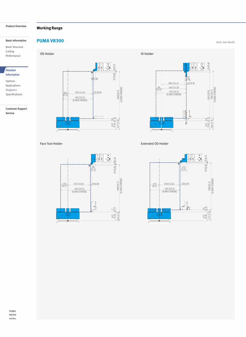
Working Range
Unit: mm (inch)
385 (15.2) 20 (0.8)
20 (0
.8)
760
(29.
9)42 (1.7
)14
3(5
.6)
185
(7.3
)78
0 (3
0.7)
(Z A
XIS
STRO
KE)
50(2.0)
405 (15.9)90(3.5)
495 (19.5)(X AXIS STROKE)
HC 15
8 (0
.3)
20 (0
.8)
34 (1.3
)14
3(5
.6)
177
(7.0
)78
0(30
.7)
(Z A
XIS
STRO
KE)
40(1.6)
395 (15.6)80(3.1)
20 (0.8)
495 (19.5)(X AXIS STROKE)
HC 15
8 (0
.3)
20 (0
.8)
34 (1.3
)14
3(5
.6)
177
(7.0
)78
0(30
.7)
(Z A
XIS
STRO
KE)
115(4.5)
320 (12.6)155(6.1)
20 (0.8)
495 (19.5)(X AXIS STROKE)
HC 15
40 (1
.6)
20 (0
.8)
2(0
.1)
143
(5.6
)14
5 (5
.7)
780(
30.7
) (Z
AXI
S ST
ROKE
)
80(3.1)
355 (14.0)120(4.7)
20 (0.8)
495 (19.5)(X AXIS STROKE)
HC 15
OD Holder
Face Tool Holder
ID Holder
Extended OD Holder
PUMA V8300
1918 /
PUMA
V8300
series
Product Overview
Basic Information
Basic Structure
Cutting
Performance
Detailed
Information
Options
Applications
Diagrams
Specifications
Customer Support
Service
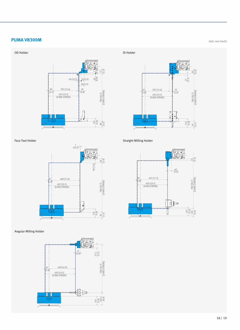
Unit: mm (inch)PUMA V8300M
780
(30.
7)(Z
AXI
S ST
ROKE
)
495 (19.5)(X AXIS STROKE)
80 (3.1)
395 (15.6) 20 (0.8)
40 (19.5) 50 (2.0)
7(0
.3)
20 (0.8
)14
3 (5
.6)
57 (2.2
)88 (3
.5)
90 (3.5)
HC 15
780
(30.
7)(Z
AXI
S ST
ROKE
)
495 (19.5)(X AXIS STROKE)
50 (2.0)
395 (15.6) 50 (2.0)
27
(1.1
)14
3 (5
.6)
50 (2.0
)95
(3
.7)
HC 15
780
(30.
7)(Z
AXI
S ST
ROKE
)
495 (19.5)(X AXIS STROKE)
47 (1.9)
448 (17.6)
7 (19.5)
40 (1
.6)
143
(5.6
)
60 (2.4
)85
(3
.3)
HC 15
780
(30.
7)(Z
AXI
S ST
ROKE
)
495 (19.5)(X AXIS STROKE)
50 (2.0)
445 (17.5)
60 (2.4)
143
(5.6
)27 (1
.1)
118
(4.6
)
HC 15
780
(30.
7)(Z
AXI
S ST
ROKE
)
495 (19.5)(X AXIS STROKE)
67 (2.6)
428 (16.9)
77 (3.0)
143
(5.6
)57
.5
(2.3
)20
2.5
(8.0
)
HC 15
OD Holder
Face Tool Holder
Angular Milling Holder
Straight Milling Holder
ID Holder
1918 /
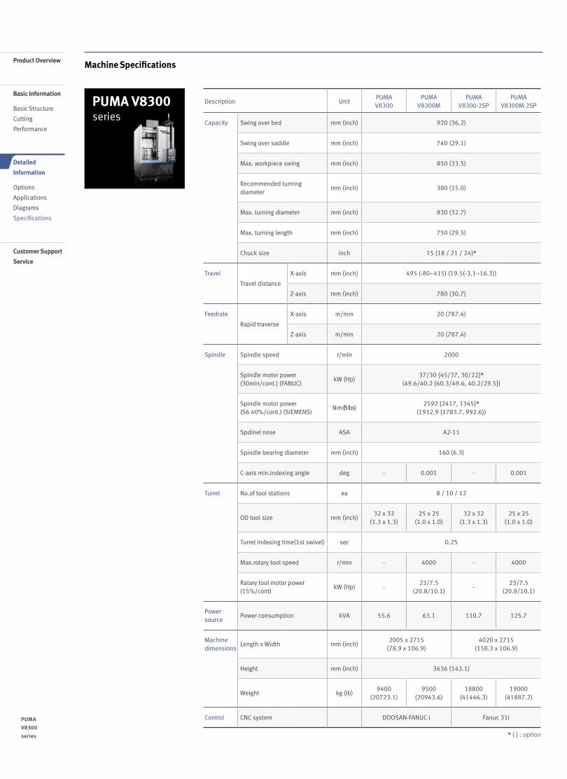
PUMA V8300 series
Machine Specifications
Description UnitPUMA V8300
PUMA V8300M
PUMA V8300-2SP
PUMA V8300M-2SP
Capacity Swing over bed mm (inch) 920 (36.2)
Swing over saddle mm (inch) 740 (29.1)
Max. workpiece swing mm (inch) 850 (33.5)
Recommended turning diameter
mm (inch) 380 (15.0)
Max. turning diameter mm (inch) 830 (32.7)
Max. turning length mm (inch) 750 (29.5)
Chuck size inch 15 {18 / 21 / 24}*
Travel
Travel distance
X-axis mm (inch) 495 (-80~415) (19.5(-3.1~16.3))
Z-axis mm (inch) 780 (30.7)
Feedrate
Rapid traverse
X-axis m/min 20 (787.4)
Z-axis m/min 20 (787.4)
Spindle Spindle speed r/min 2000
Spindle moter power(30min/cont.) (FANUC)
kW (Hp)37/30 {45/37, 30/22}*
(49.6/40.2 {60.3/49.6, 40.2/29.5})
Spindle motor power(S6 40%/cont.) (SIEMENS)
N·m (ft-lbs)2592 {2417, 1345}*
(1912.9 {1783.7, 992.6})
Spdinel nose ASA A2-11
Spindle bearing diameter mm (inch) 160 (6.3)
C-axis min.indexing angle deg - 0.001 - 0.001
Turret No.of tool stations ea 8 / 10 / 12
OD tool size mm (inch)32 x 32
(1.3 x 1.3)25 x 25
(1.0 x 1.0)32 x 32
(1.3 x 1.3)25 x 25
(1.0 x 1.0)
Turret indexing time(1st swivel) sec 0.25
Max.rotary tool speed r/min - 4000 - 4000
Ratary tool motor power(15%/cont)
kW (Hp) -23/7.5
(20.8/10.1)-
23/7.5(20.8/10.1)
Powersource
Power consumption kVA 55.6 63.1 110.7 125.7
Machinedimensions
Length x Width mm (inch)2005 x 2715
(78.9 x 106.9)4020 x 2715
(158.3 x 106.9)
Height mm (inch) 3636 (143.1)
Weight kg (lb)9400
(20723.1)9500
(20943.6)18800
(41446.3)19000
(41887.2)
Control CNC system DOOSAN-FANUC i Fanuc 31i
* { } : option
2120 /
PUMA
V8300
series
Product Overview
Basic Information
Basic Structure
Cutting
Performance
Detailed
Information
Options
Applications
Diagrams
Specifications
Customer Support
Service
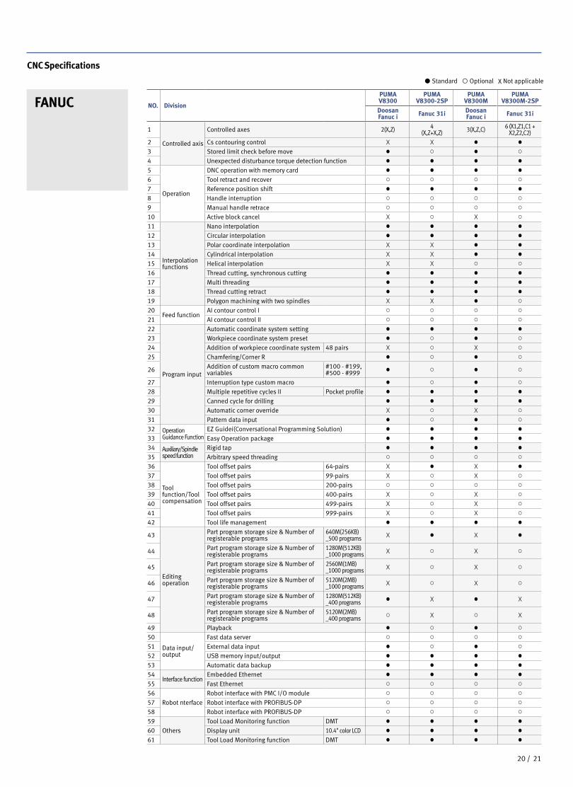
CNC Specifications
FANUC NO. Division
PUMA V8300
PUMA V8300-2SP
PUMA V8300M
PUMA V8300M-2SP
Doosan Fanuc i Fanuc 31i Doosan
Fanuc i Fanuc 31i
1
Controlled axis
Controlled axes 2(X,Z) 4(X,Z+X,Z) 3(X,Z,C) 6 (X1,Z1,C1 +
X2,Z2,C2)2 Cs contouring control X X ● ●
3 Stored limit check before move ● ○ ● ○
4 Unexpected disturbance torque detection function ● ● ● ●
5
Operation
DNC operation with memory card ● ● ● ●
6 Tool retract and recover ○ ○ ○ ○
7 Reference position shift ● ● ● ●
8 Handle interruption ○ ○ ○ ○
9 Manual handle retrace ○ ○ ○ ○
10 Active block cancel X ○ X ○
11
Interpolation functions
Nano interpolation ● ● ● ●
12 Circular interpolation ● ● ● ●
13 Polar coordinate interpolation X X ● ●
14 Cylindrical interpolation X X ● ●
15 Helical interpolation X X ○ ○
16 Thread cutting, synchronous cutting ● ● ● ●
17 Multi threading ● ● ● ●
18 Thread cutting retract ● ● ● ●
19 Polygon machining with two spindles X X ● ○
20Feed function
AI contour control I ○ ○ ○ ○
21 AI contour control II ○ ○ ○ ○
22
Program input
Automatic coordinate system setting ● ● ● ●
23 Workpiece coordinate system preset ● ○ ● ○
24 Addition of workpiece coordinate system 48 pairs X ○ X ○
25 Chamfering/Corner R ● ○ ● ○
26 Addition of custom macro common variables
#100 - #199, #500 - #999 ● ○ ● ○
27 Interruption type custom macro ● ○ ● ○
28 Multiple repetitive cycles II Pocket profile ● ● ● ●
29 Canned cycle for drilling ● ● ● ●
30 Automatic corner override X ○ X ○
31 Pattern data input ● ○ ● ○
32 Operation Guidance Function
EZ Guidei(Conversational Programming Solution) ● ● ● ●
33 Easy Operation package ● ● ● ●
34 Auxiliary/Spindle speed function
Rigid tap ● ● ● ●
35 Arbitrary speed threading ○ ○ ○ ○
36
Tool function/Tool compensation
Tool offset pairs 64-pairs X ● X ●
37 Tool offset pairs 99-pairs X ○ X ○
38 Tool offset pairs 200-pairs ○ ○ ○ ○
39 Tool offset pairs 400-pairs X ○ X ○
40 Tool offset pairs 499-pairs X ○ X ○
41 Tool offset pairs 999-pairs X ○ X ○
42 Tool life management ● ● ● ●
43
Editing operation
Part program storage size & Number of registerable programs
640M(256KB)_500 programs X ● X ●
44 Part program storage size & Number of registerable programs
1280M(512KB)_1000 programs X ○ X ○
45 Part program storage size & Number of registerable programs
2560M(1MB)_1000 programs X ○ X ○
46 Part program storage size & Number of registerable programs
5120M(2MB)_1000 programs X ○ X ○
47 Part program storage size & Number of registerable programs
1280M(512KB)_400 programs ● X ● X
48 Part program storage size & Number of registerable programs
5120M(2MB)_400 programs ○ X ○ X
49 Playback ● ○ ● ○
50
Data input/output
Fast data server ○ ○ ○ ○
51 External data input ● ○ ● ○
52 USB memory input/output ● ● ● ●
53 Automatic data backup ● ● ● ●
54Interface function
Embedded Ethernet ● ● ● ●
55 Fast Ethernet ○ ○ ○ ○
56
Robot nterface
Robot interface with PMC I/O module ○ ○ ○ ○
57 Robot interface with PROFIBUS-DP ○ ○ ○ ○
58 Robot interface with PROFIBUS-DP ○ ○ ○ ○
59
Others
Tool Load Monitoring function DMT ● ● ● ●
60 Display unit 10.4" color LCD ● ● ● ●
61 Tool Load Monitoring function DMT ● ● ● ●
Standard Optional X Not applicable
2120 /
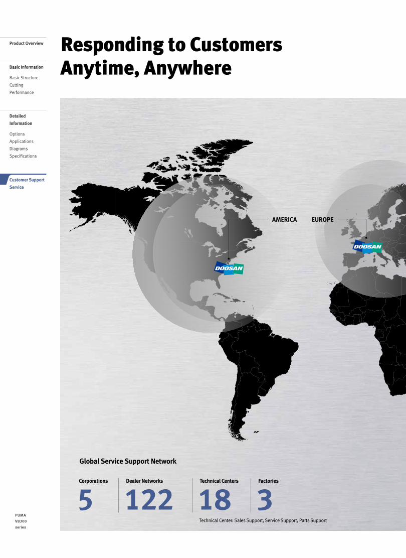
Responding to Customers Anytime, Anywhere
Global Service Support Network
Technical Center: Sales Support, Service Support, Parts Support
5Corporations
3Factories
18Technical Centers
122Dealer Networks
AMERICA EUROPE
Product Overview
Basic Information
Basic Structure
Cutting
Performance
Detailed
Information
Options
Applications
Diagrams
Specifications
Customer Support
Service
2322 /
PUMA
V8300
series
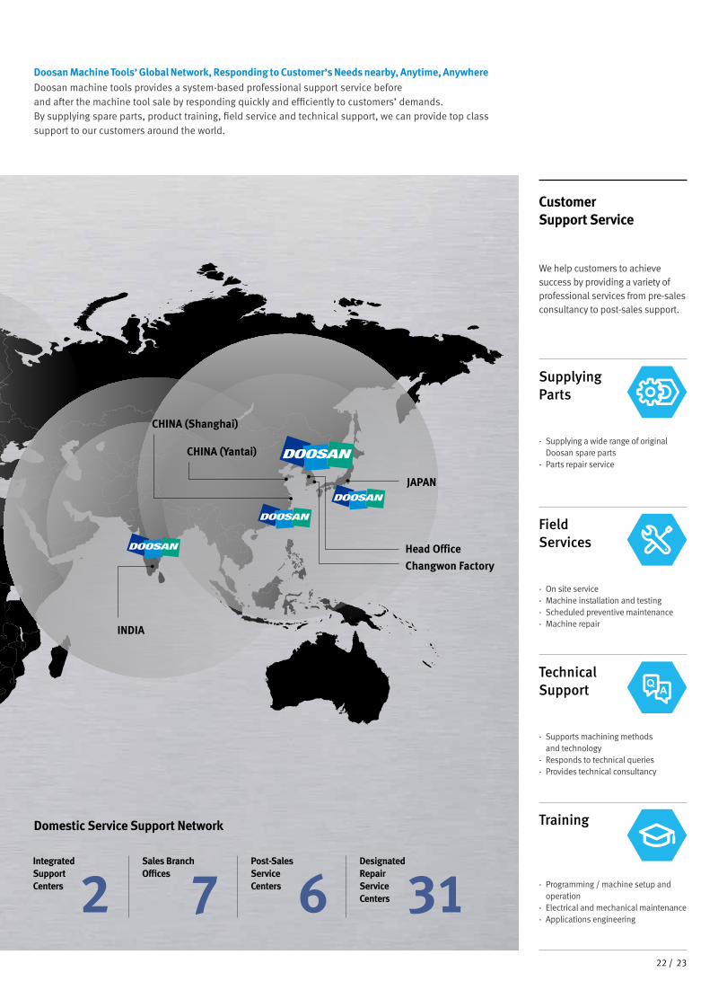
Doosan Machine Tools’ Global Network, Responding to Customer’s Needs nearby, Anytime, AnywhereDoosan machine tools provides a system-based professional support service before and after the machine tool sale by responding quickly and efficiently to customers’ demands.By supplying spare parts, product training, field service and technical support, we can provide top class support to our customers around the world.
We help customers to achieve success by providing a variety of professional services from pre-sales consultancy to post-sales support.
Customer Support Service
- On site service- Machine installation and testing- Scheduled preventive maintenance- Machine repair
Field Services
- Supports machining methods and technology
- Responds to technical queries- Provides technical consultancy
Technical Support
- Programming / machine setup and operation
- Electrical and mechanical maintenance- Applications engineering
Training
- Supplying a wide range of original Doosan spare parts
- Parts repair service
Supplying Parts
Domestic Service Support Network
2Integrated Support Centers 7
Sales Branch Offices
6Post-Sales Service Centers 31
Designated Repair Service Centers
CHINA (Yantai)
CHINA (Shanghai)
INDIA
Changwon Factory
Head Office
JAPAN
2322 /
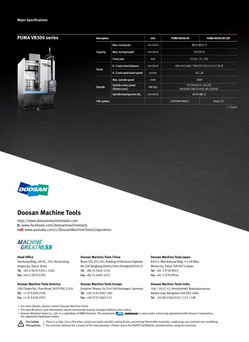
Major Specifications
PUMA V8300 series Description Unit PUMA V8300/M PUMA V8300/M-2SP
Capacity
Max. turning dia. mm (inch) Ø830 (Ø32.7)
Max. turning length mm (inch) 750 (29.5)
Chuck size inch 15 {18 / 21 / 24}*
TravelX / Z axis travel distance mm (inch) 495 (415+80) / 780 (19.5 (16.3+3.1) / 30.7)
X / Z axis rapid travel speed m/min 20 / 20
Spindle
Max. spindle speed r/min 2000
Spindle motor power(30min/cont.)
kW (Hp)37/30 {45/37, 30/22}*
(49.6/40.2 {60.3/49.6, 40.2/29.5})*
Spindle bearing inner dia. mm (inch) Ø160 (Ø6.3)
CNC system - DOOSAN FANUC i Fanuc 31i
*{ } Option
Head OfficeYeonkang Bldg., 6th FL., 270, Yeonji-dong,
Jongno-gu, Seoul, Korea
Tel +82-2-3670-5345 / 5362
Fax +82-2-3670-5382
Doosan Machine Tools America19A Chapin Rd., Pine Brook, NJ 07058, U.S.A.
Tel +1-973-618-2500
Fax +1-973-618-2501
Doosan Machine Tools ChinaRoom 101,201,301, Building 39 Xinzhuan Highway
No.258 Songjiang District,China Shanghai(201612)
Tel +86 21-5445-1155
Fax +86 21-6405-1472
Doosan Machine Tools EuropeEmdener Strasse 24, D-41540 Dormagen, Germany
Tel +49-2133-5067-100
Fax +49-2133-5067-111
Doosan Machine Tools Japan#2412, Mita Kokusai Bldg. 1-4-28 Mita,
Minato-ku, Tokyo 108-0073, Japan
Tel +81 3 5730 9013
Fax +81 3 5730 9016
Doosan Machine Tools India106 / 10-11-12, Amruthahalli, Byatarayanapura,
Bellary road, Bangalore-560 092, India
Tel +91-80-4266-0122 / 121 / 100
* For more details, please contact Doosan Machine Tools.* The specifications and information above-mentioned may be changed without prior notice.* Doosan Machine Tools Co., Ltd. is a subsidiary of MBK Partners. The trademark is used under a licensing agreement with Doosan Corporation,
the registered trademark holder.
Doosan Machine Toolshttp://www.doosanmachinetools.com
www.facebook.com/doosanmachinetools www.youtube.com/c/DoosanMachineToolsCorporation
There is a high risk or fire when using non-water-soluble cutting fluids, processing flammable materials, neglecting use coolants and modifyingthe machine without the consent of the manufacturer. Please check the SAFETY GUIDANCE carefully before using the machine.
Fire Safety Precautions