Embed Size (px)
Citation preview
RoHS
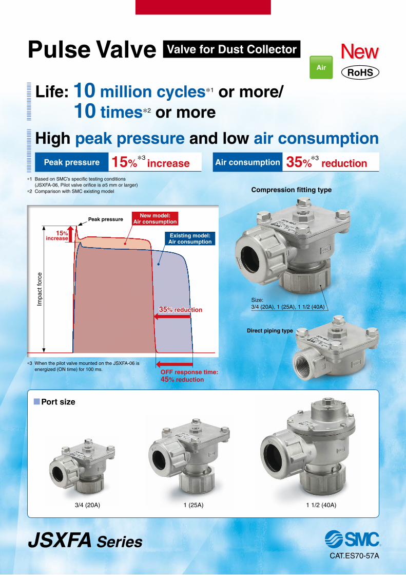
Life: 10 million cycles∗1 or more/ 10 times∗2 or more
High peak pressure and low air consumption
Impa
ct fo
rce
New model:Air consumption
Existing model:Air consumption
Peak pressure
35% reduction
MPort size
Air
15%∗3 increase
∗1 Based on SMC’s specific testing conditions (JSXFA-06, Pilot valve orifice is ø5 mm or larger)
∗2 Comparison with SMC existing model
Air consumption 35%∗3 reduction
Peak pressure
Size: 3/4 (20A), 1 (25A), 1 1/2 (40A)
Compression fitting type
Direct piping type
OFF response time: 45% reduction
3/4 (20A) 1 (25A) 1 1/2 (40A)
15%increase
∗3 When the pilot valve mounted on the JSXFA-06 is energized (ON time) for 100 ms.
CAT.ES70-57A
JSXFA Series
Pulse Valve Valve for Dust Collector
Power supply voltage
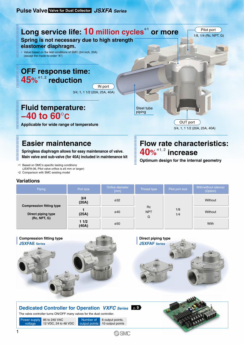
Long service life: 10 million cycles∗1 or moreSpring is not necessary due to high strength elastomer diaphragm.
OFF response time:45%∗1, 2 reduction
Fluid temperature:−40 to 60°CApplicable for wide range of temperature
Variations
Compression fitting typeJSXFAE Series
Direct piping typeJSXFAF Series
Piping Port sizeOrifice diameter
[mm]Thread type Pilot port size
With/without silencer(Option)
Compression fitting type
Direct piping type(Rc, NPT, G)
3/4(20A)
ø32
Rc
NPT
G
1/8
1/4
Without
1(25A)
ø40 Without
1 1/2(40A)
ø50 With
Pulse Valve Valve for Dust Collector JSXFA Series
Easier maintenanceSpringless diaphragm allows for easy maintenance of valve.Main valve and sub-valve (for 40A) included in maintenance kit
Flow rate characteristics:40%∗1, 2 increaseOptimum design for the internal geometry
OUT port
IN port
1/8, 1/4 (Rc, NPT, G)
3/4, 1, 1 1/2 (20A, 25A, 40A)
3/4, 1, 1 1/2 (20A, 25A, 40A)
Steel tubepiping
The valve controller turns ON/OFF many valves for the dust controller.
Dedicated Controller for Operation VXFC Series
Pilot port
p. 9
∗1 Based on SMC’s specific testing conditions (JSXFA-06, Pilot valve orifice is ø5 mm or larger)
∗2 Comparison with SMC existing model
∗ Value based on the test conditions of SMC (3/4 inch, 20A) (except the made-to-order “A”)
Number of output points
85 to 240 VAC12 VDC, 24 to 48 VDC
6 output points,10 output points
1
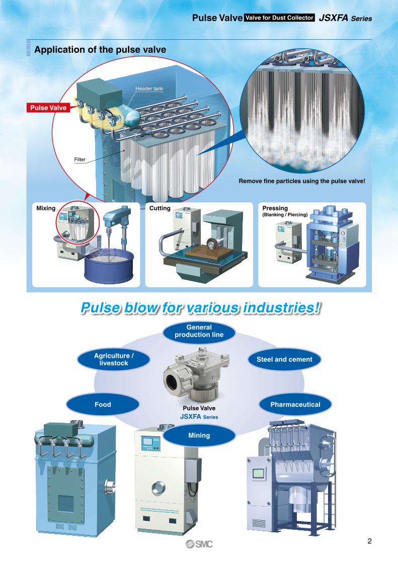
Remove fine particles using the pulse valve!
Cutting Pressing (Blanking / Piercing)
Pulse Valve
Filter
Header tank
Application of the pulse valve
Pulse ValveJSXFA Series
Generalproduction line
Mining
Steel and cement
Pharmaceutical
Agriculture / livestock
Food
Pulse blow for various industries!
Pulse Valve Valve for Dust Collector JSXFA Series
Mixing
2
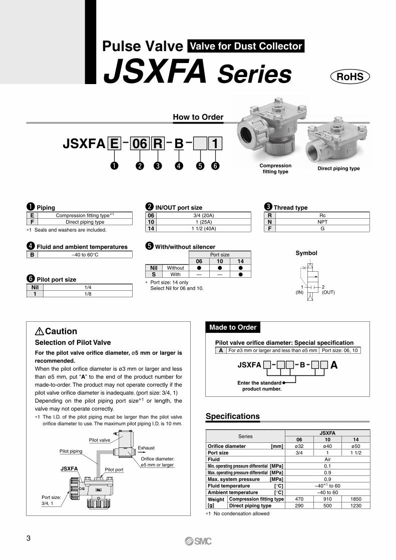
How to Order
SeriesJSXFA
06 10 14Orifice diameter [mm] ø32 ø40 ø50Port size 3/4 1 1 1/2Fluid AirMin. operating pressure differential [MPa] 0.1Max. operating pressure differential [MPa] 0.9Max. system pressure [MPa] 0.9Fluid temperature [°C] −40*1 to 60Ambient temperature [°C] −40 to 60Weight[g]
Compression fitting type 470 910 1850Direct piping type 290 500 1230
*1 No condensation allowed
JSXFA B06 RE 1
e r t ywq
w IN/OUT port size06 3/4 (20A)10 1 (25A)14 1 1/2 (40A)
y Pilot port sizeNil 1/41 1/8
Pilot valve orifice diameter: Special specificationA For ø3 mm or larger and less than ø5 mm Port size: 06, 10
Made to Order
e Thread typeR RcN NPTF G
q PipingE Compression fitting type*1
F Direct piping type
*1 Seals and washers are included.
r Fluid and ambient temperaturesB −40 to 60°C Symbol
2(OUT)
1(IN)
CautionSelection of Pilot ValveFor the pilot valve orifice diameter, ø5 mm or larger is recommended.When the pilot orifice diameter is ø3 mm or larger and less than ø5 mm, put “A” to the end of the product number for made-to-order. The product may not operate correctly if the pilot valve orifice diameter is inadequate. (port size: 3/4, 1) Depending on the pilot piping port size*1 or length, the valve may not operate correctly.*1 The I.D. of the pilot piping must be larger than the pilot valve
orifice diameter to use. The maximum pilot piping I.D. is 10 mm.Specifications
JSXFA B A
Enter the standard product number.
Compressionfitting type
Direct piping type
RoHS
Port size:3/4, 1
JSXFA
Pilot piping
Pilot valve
Pilot port
Orifice diameter:ø5 mm or larger
Exhaust
t With/without silencerPort size
06 10 14Nil Without V V V
S With — — V
* Port size: 14 only Select Nil for 06 and 10.
Pulse Valve Valve for Dust Collector
JSXFA Series
3
r
t
e
w
q
r
i
e
w
q
t
y
u
u
y
t
r
e
w
q
io!0
!1
iu
y
t
r
e
w
q
uyt o i!0
IN
IN
IN
IN
Pulse Valve Valve for Dust Collector JSXFA Series
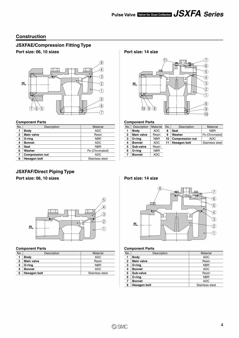
JSXFAE/Compression Fitting TypePort size: 06, 10 sizes Port size: 14 size
JSXFAF/Direct Piping TypePort size: 06, 10 sizes Port size: 14 size
Construction
Component PartsNo. Description Material1 Body ADC2 Main valve Resin3 O-ring NBR4 Bonnet ADC5 Seal NBR6 Washer Fe (Chromated)7 Compression nut ADC8 Hexagon bolt Stainless steel
Component PartsNo. Description Material1 Body ADC2 Main valve Resin3 O-ring NBR4 Bonnet ADC5 Hexagon bolt Stainless steel
Component PartsNo. Description Material1 Body ADC2 Main valve Resin3 O-ring NBR4 Bonnet ADC5 Sub-valve Resin6 O-ring NBR7 Bonnet ADC8 Hexagon bolt Stainless steel
Component PartsNo. Description Material No. Description Material1 Body ADC 8 Seal NBR2 Main valve Resin 9 Washer Fe (Chromated)3 O-ring NBR 10 Compression nut ADC4 Bonnet ADC 11 Hexagon bolt Stainless steel5 Sub-valve Resin6 O-ring NBR7 Bonnet ADC
4
A
A
øA
Silencer(Option)
(≈52)
(ø20
)
H
(F)
( E)
2 x PPort size
Pilot port1/8, 1/4 (Rc, NPT, G)
Exhaust port3/8
(G)
LM
J K(C)
(B) 20
H
(F)
( E)
2 x PPort size
(C)
(B)
Pilot port1/8, 1/4 (Rc, NPT, G)
LM
J K
JSXFA Series
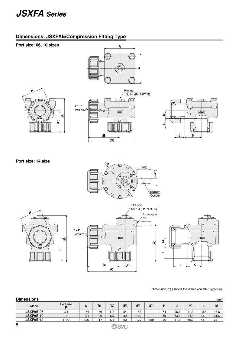
Port size: 06, 10 sizes
Port size: 14 size
Dimensions: JSXFAE/Compression Fitting Type
Dimensions [mm]
Dimension in ( ) shows the dimension after tightening.
Model Port sizeP A (B) (C) (E) (F) (G) H J K L M
JSXFAE-06 3/4 74 76 113 54 83 — 54 25.4 41.3 25.4 18.8JSXFAE-10 1 94 90 137 82 120 — 65 33.3 44.4 38.1 31.6JSXFAE-14 1 1/2 126 117 178 92 170 139 80 51.3 50.7 45 33
5
A
A
Pilot port1/8, 1/4 (Rc, NPT, G)
2 x PPort size
CB
øA
(≈52)
(ø20
)
Silencer(Option)
FE
DC
B
2 x PPort size
Pilot port1/8, 1/4 (Rc, NPT, G)
Exhaust port3/8
20
G
D
FE
A
A
Pilot port1/8, 1/4 (Rc, NPT, G)
2 x PPort size
CB
øA
(≈52)
(ø20
)
Silencer(Option)
FE
DC
B
2 x PPort size
Pilot port1/8, 1/4 (Rc, NPT, G)
Exhaust port3/8
20
G
D
FE
Pulse Valve Valve for Dust Collector JSXFA Series
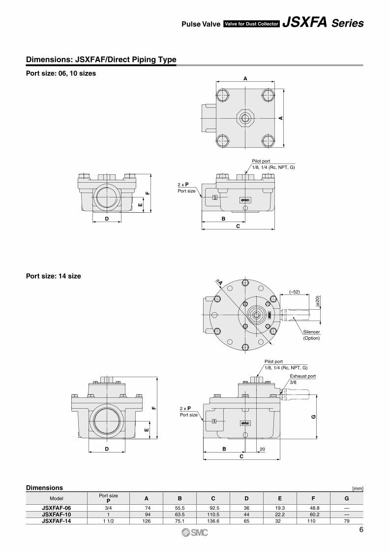
Port size: 06, 10 sizes
Port size: 14 size
Dimensions: JSXFAF/Direct Piping Type
Dimensions [mm]
Model Port sizeP A B C D E F G
JSXFAF-06 3/4 74 55.5 92.5 36 19.3 48.8 —JSXFAF-10 1 94 63.5 110.5 44 22.2 60.2 —JSXFAF-14 1 1/2 126 75.1 136.6 65 32 110 79
6
Pilot valvePilot valve
Exhaustport
Exhaustport
Exhaustport
Pressure action chamber
Pulse valve
Pulse valve
Pulse valve
Supply orifice
Main valve
Sub-valvePressure action chamber
Supply orifice
Main valve
q
q
w
q
w
IN IN
OUTOUT
JSXFA Series
Port size: 06, 10 sizes Port size: 14 size
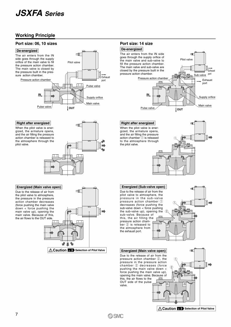
Working Principle
De-energizedThe air enters from the IN side goes through the supply orifice of the main valve and sub-valve to fill the pressure action chamber. The main valve and sub-valve are closed by the pressure built in the pressure action chamber.
Right after energizedWhen the pilot valve is ener-gized, the armature opens, and the air filling the pressure action chamber is released to the atmosphere through the pilot valve.
Right after energizedWhen the pilot valve is ener-gized, the armature opens, and the air filling the pressure action chamber q is released to the atmosphere through the pilot valve.
Energized (Main valve open)Due to the release of air from the pilot valve to atmosphere, the pressure in the pressure action chamber decreases (force pushing the main valve down < force pushing the main valve up), opening the main valve. Because of this, the air flows to the OUT side.
Energized (Sub-valve open)Due to the release of air from the pilot valve to atmosphere, the p ressu re i n t he sub -va l ve pressure action chamber q decreases (force pushing the sub-valve down < force pushing the sub-valve up), opening the sub-valve. Because of this, the air f i l l ing the pressure action cham-ber w is released to the atmosphere from the exhaust port.
Energized (Main valve open)Due to the release of air from the pressure action chamber w, the pressure in the pressure action chamber w decreases ( force pushing the main valve down < force pushing the main valve up), opening the main valve. Because of this, the air flows to the OUT side of the pulse valve.
De-energizedThe air enters from the IN side goes through the supply orifice of the main valve to fill the pressure action chamber. The main valve is closed by the pressure built in the pres-sure action chamber.
Caution Selection of Pilot Valvep. 3
Caution Selection of Pilot Valvep. 3
7
Main valve assembly
Sub-valve assembly
Main valve assembly
Hexagon bolt
Bonnet
O-ring
Main valve
Body
Hexagon bolt
Bonnet
O-ring
Sub-valve
Hexagon bolt
Bonnet
O-ring
Main valve
BodyIN side
IN side
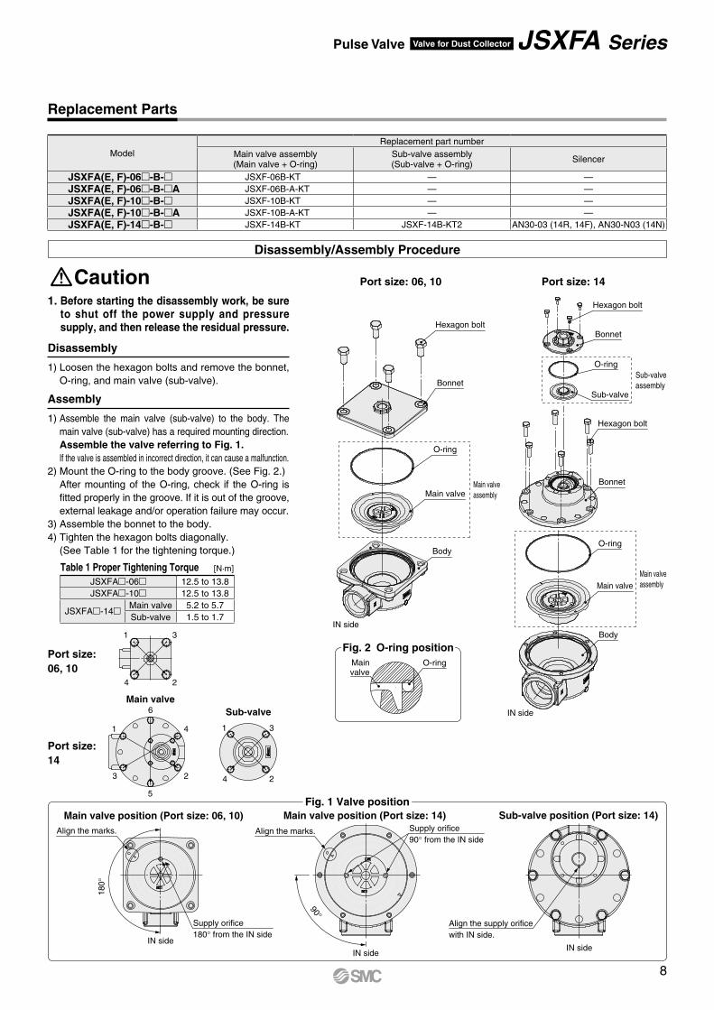
Replacement Parts
ModelReplacement part number
Main valve assembly(Main valve + O-ring)
Sub-valve assembly(Sub-valve + O-ring) Silencer
JSXFA(E, F)-06-B- JSXF-06B-KT — —JSXFA(E, F)-06-B-A JSXF-06B-A-KT — —JSXFA(E, F)-10-B- JSXF-10B-KT — —JSXFA(E, F)-10-B-A JSXF-10B-A-KT — —JSXFA(E, F)-14-B- JSXF-14B-KT JSXF-14B-KT2 AN30-03 (14R, 14F), AN30-N03 (14N)
Caution1. Before starting the disassembly work, be sure
to shut off the power supply and pressure supply, and then release the residual pressure.
1) Loosen the hexagon bolts and remove the bonnet, O-ring, and main valve (sub-valve).
Disassembly
1) Assemble the main valve (sub-valve) to the body. The main valve (sub-valve) has a required mounting direction.Assemble the valve referring to Fig. 1.If the valve is assembled in incorrect direction, it can cause a malfunction.
2) Mount the O-ring to the body groove. (See Fig. 2.)After mounting of the O-ring, check if the O-ring is fitted properly in the groove. If it is out of the groove, external leakage and/or operation failure may occur.
3) Assemble the bonnet to the body.4) Tighten the hexagon bolts diagonally.
(See Table 1 for the tightening torque.)
Assembly
Disassembly/Assembly Procedure
Main valve
5
6
3
4
2
1
4
3
2
1
Sub-valve
4
3
2
1
Table 1 Proper Tightening Torque
Port size: 06, 10
Sub-valve position (Port size: 14)Main valve position (Port size: 14)Main valve position (Port size: 06, 10)
90°
180°
IN sideIN side
IN side
Supply orifice180° from the IN side
Align the marks. Align the marks. Supply orifice90° from the IN side
Align the supply orifice with IN side.
Fig. 1 Valve position
Port size: 06, 10
Port size: 14
Port size: 14
[N·m]
JSXFA-06 12.5 to 13.8JSXFA-10 12.5 to 13.8
JSXFA-14Main valve 5.2 to 5.7Sub-valve 1.5 to 1.7
O-ringMainvalve
Fig. 2 O-ring position
8
Pulse Valve Valve for Dust Collector JSXFA Series
Powersupply
ON time
1 sec.
1 sec.
1 sec.
1 sec.
1 sec.
1 sec.
2 sec. 2 sec.1 sec. 1 sec.
2 sec. 2 sec.
2 sec.
2 sec.
2 sec.
Power switch ON (Output start) Power switch OFF (Output stop)
Two-time hitting
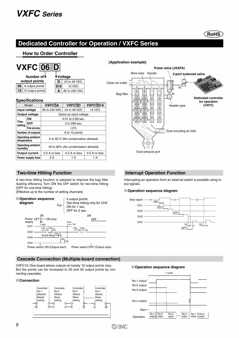
4 output points Two-time hitting only for CH2ON for 1 sec.OFF for 2 sec.
For CH1
ONt
OFFt
OFFt
OFFt
tA tA
Stop signal
CH2
CH3
CH4
1 cycle
No.1 output
No.1 output
No.1 output
No.2 output
No.2 output
No.3 output
No.n output
No.2 output
No.3 output
No.n output
Start
Operation
CH1
CH2
CH3
CH4
Controller No.1 (Master) Master setting
Controller No.2 (Slave) Slave setting
Controller No.3 (Slave) Slave setting
Controller No.n (Slave) Slave setting
Blow tube
Clean air outlet
Bag filter
Dust including air inlet
Dust exhaust port
Nozzle 2-port solenoid valve
Pulse valve (JSXFA)
IN
IN
Header pipe
VXFC Series
Specifications
How to Order Controller
DVXFC 06Number of
output pointsVoltage
Dedicated Controller for Operation / VXFC Series
Two-time Hitting Function
Cascade Connection (Multiple-board connection)
Interrupt Operation FunctionA two-time hitting function is adopted to improve the bag filter dusting efficiency. Turn ON the DIP switch for two-time hitting (OFF for one-time hitting).(Effective up to the number of setting channels)
VXFC10: One board allows outputs at merely 10 output points max.But the points can be increased to 20 and 30 output points by con-necting cascades.
Interrupting an operation from an external switch is possible using in-put signals.
M�Operation sequence diagram
MConnection
MOperation sequence diagram
MOperation sequence diagram
[Application example]
Dedicated controller for operation
(VXFC)
D 24 to 48 VDC
D-6 12 VDC
A 85 to 240 VAC
06 6 output points
10 10 output points
Model VXFC0610A VXFC06
10D VXFC0610D-6
Input voltage 85 to 240 VAC 24 to 48 VDC 12 VDC
Output voltage Same as input voltage
Time setting
ON 0.01 to 0.99 sec.
OFF 0 to 299 sec.
Time accuracy ±2%
Number of outputs 6 to 10 points
Operating ambient temperature 0 to 50°C (No condensation allowed)
Operating ambient humidity 45 to 80% (No condensation allowed)
Output current 0.5 A or less 0.5 A or less 0.5 A or less
Power supply fuse 3 A 1 A 1 A
9
5140
140
5
5
38 o
r le
ss
34 o
r le
ss
2610
or m
ore
SV9SV10
SV7SV8
SV5SV6
SV3SV4
SV1SV2
IN2IN1OUT2OUT1
2F
SW2SW1
098765432131
FFOFO
SW81 23
45678
90
0.01 to 0.99 0 to 299 secsec
OFFON
00000
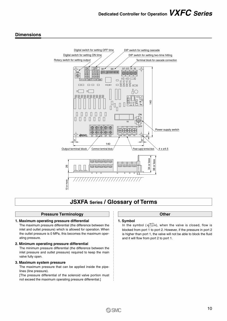
Rotary switch for setting output
Output terminal block Common terminal block 4 x ø4.5Power supply terminal block
Power supply switch
Digital switch for setting OFF time
Digital switch for setting ON time
DIP switch for setting cascade
DIP switch for setting two-time hitting
Terminal block for cascade connection
LED10LED9LED8LED7
COM FGAC2AC1
LED14
POW
LED13IN
LED12CAS
LED11
OUT
LED6LED5LED4LED3LED2LED1
1A
ON
OFF
Dimensions
Pressure Terminology Other
1. Maximum operating pressure differentialThe maximum pressure differential (the difference between the inlet and outlet pressure) which is allowed for operation. When the outlet pressure is 0 MPa, this becomes the maximum oper-ating pressure.
2. Minimum operating pressure differentialThe minimum pressure differential (the difference between the inlet pressure and outlet pressure) required to keep the main valve fully open.
3. Maximum system pressureThe maximum pressure that can be applied inside the pipe-lines (line pressure).[The pressure differential of the solenoid valve portion must not exceed the maximum operating pressure differential.]
1. SymbolIn the symbol ( ), when the valve is closed, flow is blocked from port 1 to port 2. However, if the pressure in port 2 is higher than port 1, the valve will not be able to block the fluid and it will flow from port 2 to port 1.
JSXFA Series / Glossary of Terms
10
Dedicated Controller for Operation VXFC Series
Selection
Warning3. Countermeasures against static electricity
Take measures to prevent static electricity since some fluids can cause static electricity.
4. Low temperature operation1. The valve can be used in fluid temperatures down to –40°C.
However, take measures to prevent freezing or solidification of impurities, etc.
2. When using valves for water application in cold climates, take appropriate countermeasures to prevent the water from freezing in tubing after cutting the water supply from the pump, by draining the water etc. When warming by a heater etc., be careful not to expose the coil portion to a heater. Installation of a dryer, heat retaining of the body is recom-mended to prevent a freezing condition in which the dew point temperature is high and the ambient temperature is low, and the high flow runs.
5. Fluid propertiesUse a general compressed air with a filter of 5 µm or less mounted on the inlet of the piping. (Excluding dry air)
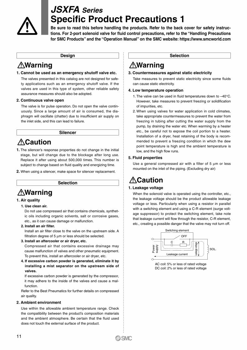
Caution1. Leakage voltage
When the solenoid valve is operated using the controller, etc., the leakage voltage should be the product allowable leakage voltage or less. Particularly when using a resistor in parallel with a switching element and using a C-R element (surge volt-age suppressor) to protect the switching element, take note that leakage current will flow through the resistor, C-R element, etc., creating a possible danger that the valve may not turn off.
AC coil: 5% or less of rated voltageDC coil: 2% or less of rated voltage
R
SOL.
OFF
Switching element
C
Leakage current Leak
age v
oltag
e
Pow
ersu
pply
Design
Warning1. Cannot be used as an emergency shutoff valve etc.
The valves presented in this catalog are not designed for safe-ty applications such as an emergency shutoff valve. If the valves are used in this type of system, other reliable safety assurance measures should also be adopted.
2. Continuous valve openThe valve is for pulse operation. Do not open the valve contin-uously. Since a large amount of air is consumed, the dia-phragm will oscillate (chatter) due to insufficient air supply on the inlet side, and this can lead to failure.
Silencer
Caution1. The silencer’s response properties do not change in the initial
stage, but will change due to the blockage after long use. Replace it after using about 500,000 times. This number is subject to change based on fluid quality and energizing time.
2. When using a silencer, make space for silencer replacement.
Selection
Warning 1. Air quality
1. Use clean air.Do not use compressed air that contains chemicals, synthet-ic oils including organic solvents, salt or corrosive gases, etc., as it can cause damage or malfunction.
2. Install an air filter.Install an air filter close to the valve on the upstream side. A filtration degree of 5 µm or less should be selected.
3. Install an aftercooler or air dryer, etc.Compressed air that contains excessive drainage may cause malfunction of valves and other pneumatic equipment. To prevent this, install an aftercooler or air dryer, etc.
4. If excessive carbon powder is generated, eliminate it by installing a mist separator on the upstream side of valves.If excessive carbon powder is generated by the compressor, it may adhere to the inside of the valves and cause a mal-function.
Refer to the Best Pneumatics for further details on compressed air quality.
2. Ambient environmentUse within the allowable ambient temperature range. Check the compatibility between the product’s composition materials and the ambient atmosphere. Be certain that the fluid used does not touch the external surface of the product.
JSXFA SeriesSpecific Product Precautions 1Be sure to read this before handling the products. Refer to the back cover for safety instruc-tions. For 2-port solenoid valve for fluid control precautions, refer to the “Handling Precautions for SMC Products” and the “Operation Manual” on the SMC website: https://www.smcworld.com
11
Piping
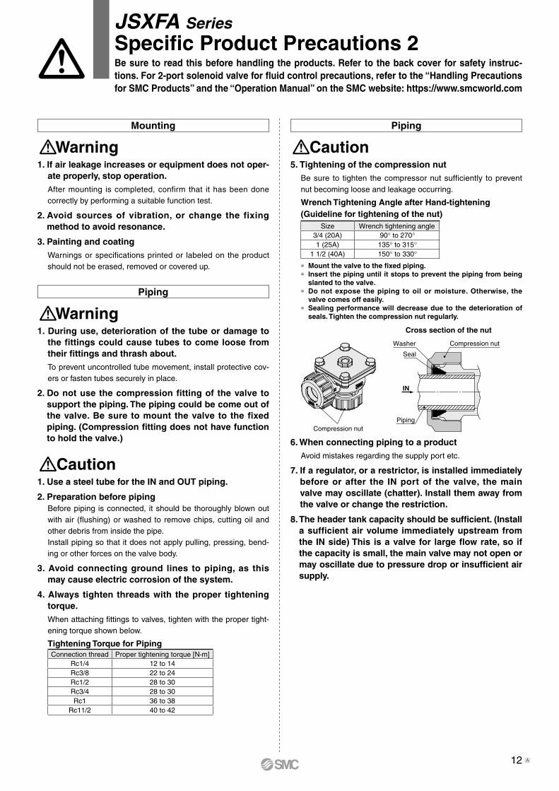
Caution5. Tightening of the compression nut
Be sure to tighten the compressor nut sufficiently to prevent nut becoming loose and leakage occurring.
Wrench Tightening Angle after Hand-tightening(Guideline for tightening of the nut)
Size Wrench tightening angle3/4 (20A) 90° to 270°1 (25A) 135° to 315°
1 1/2 (40A) 150° to 330°
∗ Mount the valve to the fixed piping.∗ Insert the piping until it stops to prevent the piping from being
slanted to the valve.∗ Do not expose the piping to oil or moisture. Otherwise, the
valve comes off easily.∗ Sealing performance will decrease due to the deterioration of
seals. Tighten the compression nut regularly.
6. When connecting piping to a productAvoid mistakes regarding the supply port etc.
7. If a regulator, or a restrictor, is installed immediately before or after the IN port of the valve, the main valve may oscillate (chatter). Install them away from the valve or change the restriction.
8. The header tank capacity should be sufficient. (Install a sufficient air volume immediately upstream from the IN side) This is a valve for large flow rate, so if the capacity is small, the main valve may not open or may oscillate due to pressure drop or insufficient air supply.
Cross section of the nut
Compression nut
Compression nutPiping
Seal
Washer
IN
Mounting
Warning 1. If air leakage increases or equipment does not oper-
ate properly, stop operation.After mounting is completed, confirm that it has been done correctly by performing a suitable function test.
2. Avoid sources of vibration, or change the fixing method to avoid resonance.
3. Painting and coatingWarnings or specifications printed or labeled on the product should not be erased, removed or covered up.
Piping
Warning 1. During use, deterioration of the tube or damage to
the fittings could cause tubes to come loose from their fittings and thrash about.To prevent uncontrolled tube movement, install protective cov-ers or fasten tubes securely in place.
2. Do not use the compression fitting of the valve to support the piping. The piping could be come out of the valve. Be sure to mount the valve to the fixed piping. (Compression fitting does not have function to hold the valve.)
Caution1. Use a steel tube for the IN and OUT piping.
2. Preparation before pipingBefore piping is connected, it should be thoroughly blown out with air (flushing) or washed to remove chips, cutting oil and other debris from inside the pipe.Install piping so that it does not apply pulling, pressing, bend-ing or other forces on the valve body.
3. Avoid connecting ground lines to piping, as this may cause electric corrosion of the system.
4. Always tighten threads with the proper tightening torque.When attaching fittings to valves, tighten with the proper tight-ening torque shown below.
Tightening Torque for PipingConnection thread Proper tightening torque [N·m]
Rc1/4 12 to 14Rc3/8 22 to 24Rc1/2 28 to 30Rc3/4 28 to 30Rc1 36 to 38
Rc11/2 40 to 42
JSXFA SeriesSpecific Product Precautions 2Be sure to read this before handling the products. Refer to the back cover for safety instruc-tions. For 2-port solenoid valve for fluid control precautions, refer to the “Handling Precautions for SMC Products” and the “Operation Manual” on the SMC website: https://www.smcworld.com
12 A
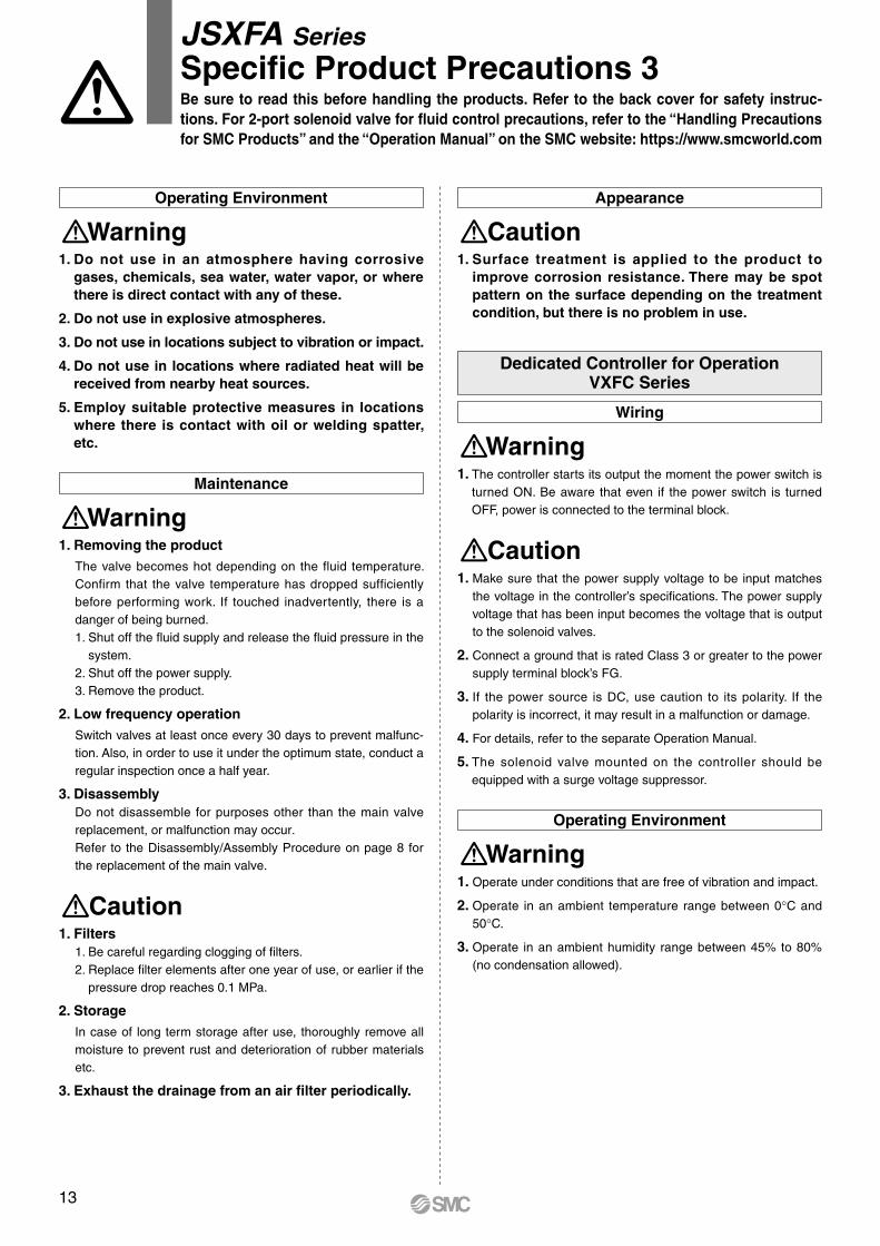
Appearance
Caution1. Surface treatment is applied to the product to
improve corrosion resistance. There may be spot pattern on the surface depending on the treatment condition, but there is no problem in use.
condition, but there is no problem in use.
Wiring
Warning 1. The controller starts its output the moment the power switch is
turned ON. Be aware that even if the power switch is turned OFF, power is connected to the terminal block.
Caution1. Make sure that the power supply voltage to be input matches
the voltage in the controller’s specifications. The power supply voltage that has been input becomes the voltage that is output to the solenoid valves.
2. Connect a ground that is rated Class 3 or greater to the power supply terminal block’s FG.
3. If the power source is DC, use caution to its polarity. If the polarity is incorrect, it may result in a malfunction or damage.
4. For details, refer to the separate Operation Manual.
5. The solenoid valve mounted on the controller should be equipped with a surge voltage suppressor.
Operating Environment
Warning 1. Operate under conditions that are free of vibration and impact.
2. Operate in an ambient temperature range between 0°C and 50°C.
3. Operate in an ambient humidity range between 45% to 80% (no condensation allowed).
Dedicated Controller for OperationVXFC Series
Operating Environment
Warning 1. Do not use in an atmosphere having corrosive
gases, chemicals, sea water, water vapor, or where there is direct contact with any of these.
2. Do not use in explosive atmospheres.
3. Do not use in locations subject to vibration or impact.
4. Do not use in locations where radiated heat will be received from nearby heat sources.
5. Employ suitable protective measures in locations where there is contact with oil or welding spatter, etc.
Maintenance
Warning 1. Removing the product
The valve becomes hot depending on the fluid temperature. Confirm that the valve temperature has dropped sufficiently before performing work. If touched inadvertently, there is a danger of being burned. 1. Shut off the fluid supply and release the fluid pressure in the
system.2. Shut off the power supply.3. Remove the product.
2. Low frequency operationSwitch valves at least once every 30 days to prevent malfunc-tion. Also, in order to use it under the optimum state, conduct a regular inspection once a half year.
3. DisassemblyDo not disassemble for purposes other than the main valve replacement, or malfunction may occur.Refer to the Disassembly/Assembly Procedure on page 8 for the replacement of the main valve.
Caution1. Filters
1. Be careful regarding clogging of filters.2. Replace filter elements after one year of use, or earlier if the
pressure drop reaches 0.1 MPa.
2. StorageIn case of long term storage after use, thoroughly remove all moisture to prevent rust and deterioration of rubber materials etc.
3. Exhaust the drainage from an air filter periodically.
JSXFA SeriesSpecific Product Precautions 3Be sure to read this before handling the products. Refer to the back cover for safety instruc-tions. For 2-port solenoid valve for fluid control precautions, refer to the “Handling Precautions for SMC Products” and the “Operation Manual” on the SMC website: https://www.smcworld.com
13
Safety Instructions Be sure to read the “Handling Precautions for SMC Products” (M-E03-3) and “Operation Manual” before use.
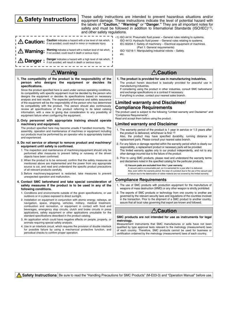
CautionSMC products are not intended for use as instruments for legal metrology.Measurement instruments that SMC manufactures or sells have not been qualified by type approval tests relevant to the metrology (measurement) laws of each country. Therefore, SMC products cannot be used for business or certification ordained by the metrology (measurement) laws of each country.
Compliance Requirements
∗1) ISO 4414: Pneumatic fluid power – General rules relating to systems. ISO 4413: Hydraulic fluid power – General rules relating to systems. IEC 60204-1: Safety of machinery – Electrical equipment of machines. (Part 1: General requirements) ISO 10218-1: Manipulating industrial robots – Safety. etc.
Caution indicates a hazard with a low level of risk which, if not avoided, could result in minor or moderate injury.Caution:Warning indicates a hazard with a medium level of risk which, if not avoided, could result in death or serious injury.Warning:
Danger : Danger indicates a hazard with a high level of risk which, if not avoided, will result in death or serious injury.
Warning Caution1. The compatibility of the product is the responsibility of the
person who designs the equipment or decides its specifications.Since the product specified here is used under various operating conditions, its compatibility with specific equipment must be decided by the person who designs the equipment or decides its specifications based on necessary analysis and test results. The expected performance and safety assurance of the equipment will be the responsibility of the person who has determined its compatibility with the product. This person should also continuously review all specifications of the product referring to its latest catalog information, with a view to giving due consideration to any possibility of equipment failure when configuring the equipment.
2. Only personnel with appropriate training should operate machinery and equipment.The product specified here may become unsafe if handled incorrectly. The assembly, operation and maintenance of machines or equipment including our products must be performed by an operator who is appropriately trained and experienced.
3. Do not service or attempt to remove product and machinery/equipment until safety is confirmed.1. The inspection and maintenance of machinery/equipment should only be
performed after measures to prevent falling or runaway of the driven objects have been confirmed.
2. When the product is to be removed, confirm that the safety measures as mentioned above are implemented and the power from any appropriate source is cut, and read and understand the specific product precautions of all relevant products carefully.
3. Before machinery/equipment is restarted, take measures to prevent unexpected operation and malfunction.
4. Contact SMC beforehand and take special consideration of safety measures if the product is to be used in any of the following conditions. 1. Conditions and environments outside of the given specifications, or use
outdoors or in a place exposed to direct sunlight.2. Installation on equipment in conjunction with atomic energy, railways, air
navigation, space, shipping, vehicles, military, medical treatment, combustion and recreation, or equipment in contact with food and beverages, emergency stop circuits, clutch and brake circuits in press applications, safety equipment or other applications unsuitable for the standard specifications described in the product catalog.
3. An application which could have negative effects on people, property, or animals requiring special safety analysis.
4. Use in an interlock circuit, which requires the provision of double interlock for possible failure by using a mechanical protective function, and periodical checks to confirm proper operation.
1. The product is provided for use in manufacturing industries.The product herein described is basically provided for peaceful use in manufacturing industries. If considering using the product in other industries, consult SMC beforehand and exchange specifications or a contract if necessary. If anything is unclear, contact your nearest sales branch.
Limited warranty and Disclaimer/Compliance RequirementsThe product used is subject to the following “Limited warranty and Disclaimer” and “Compliance Requirements”.Read and accept them before using the product.
Limited warranty and Disclaimer1. The warranty period of the product is 1 year in service or 1.5 years after
the product is delivered, whichever is first.∗2)
Also, the product may have specified durability, running distance or replacement parts. Please consult your nearest sales branch.
2. For any failure or damage reported within the warranty period which is clearly our responsibility, a replacement product or necessary parts will be provided. This limited warranty applies only to our product independently, and not to any other damage incurred due to the failure of the product.
3. Prior to using SMC products, please read and understand the warranty terms and disclaimers noted in the specified catalog for the particular products.
∗2) Vacuum pads are excluded from this 1 year warranty.A vacuum pad is a consumable part, so it is warranted for a year after it is delivered. Also, even within the warranty period, the wear of a product due to the use of the vacuum pad or failure due to the deterioration of rubber material are not covered by the limited warranty.
1. The use of SMC products with production equipment for the manufacture of weapons of mass destruction (WMD) or any other weapon is strictly prohibited.
2. The exports of SMC products or technology from one country to another are governed by the relevant security laws and regulations of the countries involved in the transaction. Prior to the shipment of a SMC product to another country, assure that all local rules governing that export are known and followed.
These safety instructions are intended to prevent hazardous situations and/or equipment damage. These instructions indicate the level of potential hazard with the labels of “Caution,” “Warning” or “Danger.” They are all important notes for safety and must be followed in addition to International Standards (ISO/IEC)∗1), and other safety regulations.
Safety Instructions


![Pulse Blowing Valve - content2.smcetech.com · Type of actuation C [dm3/(s·bar)] b Cv External pilot 14 0.18 3.4 Internal pilot 12 0.14 2.9 Features ON (Valve open) OFF (Valve closed)](https://img.pdfslide.us/doc/110x75/5f78aca1b776265920542ef1/pulse-blowing-valve-type-of-actuation-c-dm3sbar-b-cv-external-pilot-14-018.jpg)