Embed Size (px)
Citation preview

Pulse PointTM II Series: Vibrating Rod
Installation & Operation Manual
IOM
LVP1
8091
4 Re
v. D


Pulse PointTM II Series: Rod ConfigurationInstallation & Operation Manual
CONTENTS
I. HANDLING & STORAGE ..................................................................................................................................................................1
II. GENERAL SAFETY .............................................................................................................................................................................2
III. PRODUCT DESCRIPTION ...............................................................................................................................................................3
IV. MECHANICAL INSTALLATION ......................................................................................................................................................5
V. ELECTRICAL INSTALLATION ..........................................................................................................................................................7
VI. SET-UP ........................................................................................................................................................................................... 14
VII. MAINTENANCE .............................................................................................................................................................................. 18
VIII. TROUBLESHOOTING .................................................................................................................................................................... 18
SAFETY SYMBOLS
WARNING:
IDENTIFIES CONDITIONS OR PROCEDURES, WHICH IF NOT FOLLOWED, COULD RESULT IN SERIOUS INJURY. RISK OF ELECTRICAL SHOCK.
CAUTION:
IDENTIFIES CONDITIONS OR PROCEDURES, WHICH IF NOT FOLLOWED, COULD RESULT IN SERIOUS DAMAGE OR FAILURE OF THE EQUIPMENT.
1
www.bindicator.com
LVP180914 Rev. D
Pulse Point II Series: Rod ConfigurationInstallation & Operation Manual
I. HANDLING AND STORAGE
SAVE THESE INSTRUCTIONS
INSPECTION AND HANDLING
Do not dispose of the carton or packing materials.
Each package should be inspected upon receipt for damage that may have occurred due to mishandling during
shipping. If the unit is received damaged, notify the carrier or the factory for instructions. Failure to do so may
void your warranty. If you have any problems or questions, consult Customer Support at 800-778-9242.
DISPOSAL AND RECYCLING
This product can be recycled by specialized companies and must not be disposed of in a municipal collection
site. If you do not have the means to dispose of properly, please contact for return and disposal instructions or
options.
STORAGE
If the device is not scheduled for immediate installation following delivery, the following steps should be
observed:
1. Following inspection, repackage the unit into its original packaging.
2. Select a clean dry site, free of vibration, shock and impact hazards.
3. If storage will be extended longer than 30 days, the unit must be stored at temperatures between 32º and 158º F (0º to 70° C) in non-condensing atmosphere with humidity less than 85%.
CAUTION: DO NOT STORE A NON-POWERED UNIT OUTDOORS FOR A PROLONGED PERIOD.
2 LVP180914 Rev. D
www.bindicator.com
II. GENERAL SAFETY
AUTHORIZED PERSONNEL
All instructions described in this document must be performed by authorized and qualified service personnel only.
Before installing the unit, please read these instructions and familiarize yourself with the requirements and functions of
the device. The required personal protective equipment must always be worn when servicing this device.
USE
The device is solely intended for use as described in this manual. Reliable operation is ensured only if the
instrument is used according to the specifications described in this document. For safety and warranty
reasons, use of accessory equipment not recommended by the manufacturer or modification of this device is
explicitly forbidden. All servicing of this equipment must be performed by qualified service personnel only. This
device should be mounted in locations where it will not be subject to tampering by unauthorized personnel.
MISUSE
Improper use or installation of this device may cause the following:
• Personal injury or harm
• Application specific hazards such as vessel overfill
• Damage to the device or system
If any questions or problems arise during installation of this equipment, please contact Product Support at 800-778-
9242.
WARNING: ONLY CERTAIN MODELS CAN BE USED IN HAZARDOUS LOCATIONS; SEE NAMEPLATE. THESE MODELS
SHALL ONLY BE USED IN APPLICATIONS COVERED BY THE STATED RATINGS OR NON-HAZARDOUS LOCATIONS.

3
www.bindicator.com
LVP180914 Rev. D
III. PRODUCT DESCRIPTION
FUNCTION
The LP® II Series is an electronic, vibratory level control designed for use in powders and granular solids. A vibrating rod is
used to sense the presence of material.
The rod contains two piezoelectric crystal assemblies. The Piezo crystals convert electrical signals to mechanical
movement, and vice versa.
When material comes in contact with the rod it will cause a reduction in the level of vibration. If the reduction of the
vibration is greater than the set threshold determined by the sensitivity setting the alarm relay will turn ON or OFF
depending on the fail-safe settings.
APPLICATIONS
Unlike radio frequency and capacitance technology sensors, the LP II Series devices sense material using a mechanical
principle and are therefore not affected by the dielectric constant of the material. These are ideal sensors in plastics, dust,
shavings, and low-density powders and food. The rod is more often used in larger size materials such as gravel or pellets.
FEATURES
Universal input power; AC or DC (see specifications for input ranges)
No calibration required
Adjustable time delay
Selectable fail-safe operation (high or low level)
Adjustable Sensitivity

4 LVP180914 Rev. D
www.bindicator.com
TECHNICAL SPECIFICATIONS: ROD CONFIGURATIONS
FUNCTIONAL
Power Requirements Universal (± 10%), 120-240 VAC 50/60 Hz or 24-48 VDCPower Consumption 4 W AC; 4 W DC
Fuse Slow Blow, 0.5 A 300 V (Not User Serviceable)
Operating TemperatureElectronics: Ordinary Location -40° to 158° F (-40° to 70° C)Electronics: Hazardous Location -4° to 158° F (-20° to 70° C)Electronics: Hazardous Location -T -40° to 158° F (-40° to 70° C)Process: Standard Temperature -22° to 203° F (-30° to 95° C)Process: High Temperature -22° to 320° F (-30° to 160° C)
Outputs
Main Relay 8 A DPDT @ 240 VAC or 30 VDC (resistive)
Auxiliary Relay - ADVANCED ONLY 0.46 A SPDT @ 150 VAC or 1 A @ 30 VDC
PERFORMANCE
Pressure Rating 150 psi (10.5 kg/cm2) with 3/4” NPT; 50 psi (3.5 kg/cm2) with 1 1/4” NPT
Time Delay - STANDARD Field Adjustable; Up to 6 seconds
Time Delay - ADVANCED Field Adjustable; Up to 150 seconds
Fail Safe Field Selectable; high/low level
Sensitivity - STANDARD Minimum 6 lbs/ ft3 (96 kg/m3); Field Adjustable
Sensitivity - ADVANCED Minimum 3 lbs/ft3 (48 kg/m3); Field AdjustableRemote Distance 50 ft. (15 m) Max
PHYSICAL
Enclosure Material Powder or Epoxy Coated Aluminum or 304 SS
Process FittingNPT 3/4”, 11/4” ,11/2” BSP R 11/4” ,11/2” BSP G 11/4” ,11/2”
Rod Material 316 Stainless Steel
Dual Conduit Entry 3/4” NPT or M20 x 1.5Mounting Plate Material Mild Steel, 304 Stainless Steel
Extended Pipe Material 316 Stainless Steel
Shipping Weight Integral, non-extended 10 lb (4.5 kg)
Pollution Degree 2
Installation Category II
Altitude 6,562 ft (2,000 m)
APPROVALS & RATINGS
UL:Ordinary Location Type 4X; IP66 (US and Canada)Hazardous Location, Type 4X Explosion Proof, Class I, Div 1, Groups C, D (US Only) Dust Ignition Proof, Class II, Div 1, Groups E, F, G (US and Canada)
CEElectromagnetic Compatibility DirectiveLow Voltage Directive

5
www.bindicator.com
LVP180914 Rev. D
IV. MECHANICAL INSTALLATION
The following precautions should be observed when installing and operating an LP II device:
• The installation and wiring of this product must comply with all national, federal, state, municipal and local codes that apply.
• The LP II Series are precision devices - handle carefully to prevent damage to the rod.
• Do not allow moisture to enter the electronics enclosure. Conduit should slope downward from the LP II housing. Install drip loops (or drain fitting) and seal conduit with silicone rubber product.
• The resonant frequency of the rod is 400 Hz (±10%); locations subject to vibration frequencies greater than 100 Hz should be avoided.
CAUTION: WHEN MOUNTING UNITS, NEVER ADJUST THE ORIENTATION BY TURNING THE HOUSING. USE A
WRENCH FOR PROCESS FITTING UNITS, OTHERWISE A STRAP WRENCH SHOULD BE USED TO TIGHTEN INTO PLACE.
ATTEMPTING TO TIGHTEN THE UNIT BY ROTATING THE HOUSING OR ROD MAY DAMAGE THE UNIT
AND VOID THE WARRANTY.
CAUTION: WHETHER MOUNTING DIRECTLY THROUGH A SIDE WALL, OR PIPE EXTENDED AND
MOUNTED VERTICALLY THROUGH THE TOP OF A VESSEL, NEVER ATTEMPT TO MOUNT THROUGH
A FULL COUPLING.
WARNING: HIGH VOLTAGE IS PRESENT. REMOVE POWER FROM THE UNIT BEFORE INSTALLING, REMOVING, OR
MAKING ADJUSTMENTS.
WARNING: IN ORDER TO MAINTAIN SAFE OPERATION IN HAZARDOUS LOCATIONS, THE INTEGRITY OF THE
ALUMINUM CASTING AND THE ENVIRONEMENTAL SEALS MUST BE MAINTAINED. THE USER/INSTALLER
MUST AVOID INSTALLATIONS WHERE AGGRESSIVE SUBSTANCES MAY BE PRESENT AND COULD AFFECT THE
PERFORMANCE OF THESE MATERIALS. CARE MUST ALSO BE EXERCISED WHEN REMOVING AND REPLACING THE
COVER, SO NO MARRING, SCRATCHING OR DAMAGE OCCURS TO THE FLANGES, AND THAT FLANGE SURFACES
REMAIN COMPLETELY CLEANED OF DEBRIS.
WARNING: FOR UNITS INSTALLED IN HAZARDOUS LOCATIONS, TO REDUCE THE RISK OF IGNITION OF HAZARDOUS
ATMOSPHERES, CONDUIT RUNS MUST HAVE A SEALING FITTING CONNECTION WITHIN 18 IN. OF THE ENCLOSURE.
WARNING: FOR PRODUCTS MARKED AS TYPE 4X, USE TYPE 4X HUB FITTING; FOR IP66 USE IP66 HUB FITTING.
GUIDELINES
6 LVP180914 Rev. D
www.bindicator.com
The LP II unit must be located at the position where level indication is desired. The unit may be mounted through the top
or side wall of the vessel. To ensure reliable operation, observe the following guidelines when choosing the mounting
location.
If using a remote unit, remote turtle cannot be mounted more than 50 feet (15m) away from the probe.
DO NOT mount the unit in an area where the rod can contact the vessel.
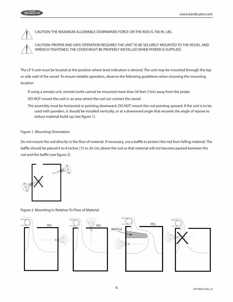
The assembly must be horizontal or pointing downward. DO NOT mount the rod pointing upward. If the unit is to be used with powders, it should be installed vertically, or at a downward angle that exceeds the angle of repose to reduce material build-up (see figure 1).
Figure 1. Mounting Orientation
Do not mount the rod directly in the flow of material. If necessary, use a baffle to protect the rod from falling material. The
baffle should be placed 6 to 8 inches (15 to 20 cm) above the rod so that material will not become packed between the
rod and the baffle (see figure 2).
Figure 2. Mounting In Relation To Flow of Material
YES YES YES
BAFFLE
CAUTION: THE MAXIMUM ALLOWABLE DOWNWARD FORCE ON THE ROD IS 700 IN. LBS.
CAUTION: PROPER AND SAFE OPERATION REQUIRES THE UNIT TO BE SECURELY MOUNTED TO THE VESSEL AND WRENCH TIGHTENED. THE COVER MUST BE PROPERLY INSTALLED WHEN POWER IS SUPPLIED.

7
www.bindicator.com
LVP180914 Rev. D
V. ELECTRICAL INSTALLATION
WARNING: HIGH VOLTAGE IS PRESENT. REMOVE POWER FROM THE UNIT BEFORE INSTALLING, REMOVING, OR MAKING ADJUSTMENTS.
WARNING: FOR UNITS INSTALLED IN HAZARDOUS LOCATIONS, TO REDUCE THE RISK OF IGNITION OF
HAZARDOUS ATMOSPHERE, CONDUIT RUNS MUST HAVE A SEALING FITTING CONNECTING WITHIN 18 IN. OF
THE ENCLOSURE.
WARNING: FOR PRODUCTS MARKED AS TYPE 4X, USE TYPE 4X HUB FITTING; FOR IP66 USE IP66 HUB FITTING.
CAUTION: IF THE UNIT WAS SUPPLIED WITH A GASKET, AVOID FOLDING, CUTTING OR TEARING THE GASKET.
DAMAGING THE GASKET CAN ALLOW MOISTURE TO ENTER THE ENCLOSURE AND DAMAGE THE UNIT.
CAUTION: TO REDUCE THE RISK OF IGNITION IN HAZARDOUS ATMOSPHERES, DISCONNECT THE EQUIPMENT
FROM SUPPLY CIRCUIT BEFORE OPENING. KEEP ASSEMBLY TIGHTLY CLOSED WHEN IN OPERATION.
CAUTION: PROPER AND SAFE OPERATION REQUIRES THE UNIT TO BE SECURELY MOUNTED TO THE VESSEL
AND WRENCH TIGHTENED. THE COVER MUST BE PROPERLY INSTALLED WHEN POWER IS APPLIED.
GENERAL SAFETY
When using electrical equipment, you should always follow basic safety precautions, including the following:
• The installation and wiring of this product must comply with all national, federal, state, municipal, and local codes that apply.
• Properly ground the enclosure to an adequate earth ground.
• Do not modify any factory wiring. Connections should only be made to the terminals described in this section.
• All connections to the LP II Series models must use conductors with an insulation rating of 300 V minimum, rated for 212º F (105º C), a minimum flammability rating of VW-1, and be of appropriate gauge for the voltage and current required (See Specifications).
• Do not allow moisture to enter the electronics enclosure. Conduit should slope downward from the LP II housing. Install drip loops and seal conduit with silicone rubber product.
DISCONNECT REQUIREMENTS FOR PERMANENTLY INSTALLED EQUIPMENT
A dedicated disconnecting device (circuit breaker) must be provided for the proper installation of the unit. If independent
circuits are used for power input and main relay outputs, individual disconnects are required. Disconnects must meet the
following requirements:
• Located in close proximity to the device
• Easily accessible to the operator
8 LVP180914 Rev. D
www.bindicator.com
• Appropriately marked as the disconnect for the device and associated circuit
• Sized appropriately to the requirements of the protected circuit (See Specifications)
PROTECTIVE EARTH GROUND
To eliminate shock hazards in the unlikely event of an internal insulation breakdown, the unit is provided with an “earth”
lead which must be connected to earth ground. In addition, the input power ground lead must be connected to the
“protective earth” ( ) terminal provided. Wire sizes must be selected such that it can safely carry the sum total of all
circuits’ maximum amperage.
CONDUIT CABLE CONNECTION
Two threaded female conduit openings are provided in the housing for input and output wiring. When only one
conduit opening is used for installation, the unused opening must be sealed with a suitable type 4X/IP66 plug
with pipe sealant in order to maintain approval requirements.
ELECTRICAL CONNECTIONS
Note: The LP II can be operated from 120-240 VAC 50/60 Hz or 24-48 VDC and provides reverse polarity
protection in the event of a wiring error.
LP II SERIES INTEGRAL MODEL ONLY
Input Power Connections
1. Refer to Figures 3 or 4 and 5 when connecting input power to the unit.
2. Loosen the housing cover screws and remove cover.
CAUTION: IF THE UNIT WAS SUPPLIED WITH A GASKET AVOID FOLDING, CUTTING, OR TEARING GASKET.
DAMAGING THE GASKET CAN ALLOW MOISTURE TO ENTER THE ENCLOSURE AND DAMAGE THE UNIT.
Note: Two threaded female conduit openings are provided in the housing to separate input and output wiring.
3. Pull approximately 4.5” of cable through conduit closest to the grounding bracket and strip as follows:
a. Ground – 3/8” (9 to 10 mm)
b. Power Leads – 1/4” (6 to 7 mm)
4. Attach incoming ground lead to grounding bracket as shown in Figure 5.
Note: The LP II incorporates pluggable terminal blocks for ease of connection. If the terminal block is unplugged while
making connections, ensure it is seated properly when reinstalled.
5. Attach power leads to terminal block as shown in Figure 3 or 4. (3.5 in-lb, 0.4 N-m)
6. Check that all wires are held tightly in place by lightly pulling each conductor.
Main Relay Connections

9
www.bindicator.com
LVP180914 Rev. D
7. Refer to Figures 3 or 4 and 6 when connecting to the main relay.
8. Pull approximately 4.5” (11.43 cm) of cable through conduit and strip 1/4” (6 to 7 mm).
9. Attach leads to terminal block as shown in Figure 6. (3.5 in-lb, 0.4 N-m)
10. Check that all wires are held tightly in place by lightly pulling each conductor.
For STANDARD models skip to Step 15; for ADVANCED models continue to Step 11.
Auxiliary Relay Connections - ADVANCED MODEL ONLY
11. Refer to Figures 4 and 7 when connecting to the auxiliary relay.
12. Pull approximately 5.5” (13.97 cm) of cable through conduit and strip 1/4” (6 to 7 mm).
13. Attach leads to terminal block as shown in Figure 7. (2.0 in-lb, 0.23 N-m)
14. Check that all wires are held tightly in place by lightly pulling each conductor.
15. Reinstall the gasket, if necessary.
16. Replace cover and tighten screws to 60 in-lb (6.8 N-m) of torque.
LP II SERIES REMOTE MODEL ONLY
Input Power Connections
1. Refer to Figures 8 or 9 and 5 when connecting input power to the unit.
2. Loosen set screw that locks cover in place.
3. Unscrew the housing cover and remove.
Note: Two threaded female conduit openings are provided in the remote housing to separate input and output wiring
from the remote rod wiring.
4. Pull approximately 6” (15.24 cm) of cable through conduit closest to grounding bracket and strip as
follows:
a. Ground – 3/8” (9 to 10 mm)
b. Power Leads – 1/4” (6 to 7 mm)
5. Attach incoming ground lead to grounding bracket as shown in Figure 5.
Note: The LP II incorporates pluggable terminal blocks for ease of connection. If the terminal block is unplugged while
making connections, ensure it is seated properly when reinstalled.
6. Attach power leads to terminal block as shown in Figure 8 or 9. (3.5 in-lb, 0.4 N-m)
7. Check that all wires are held tightly in place by lightly pulling each conductor.
Main Relay Connections
8. Refer to Figures 8 or 9 and 6 when connecting to the main relay.
9. Pull approximately 9” (22.86 cm) of cable through conduit and strip 1/4” (6 to 7 mm).
10. Attach leads to terminal block as shown in Figure 6. (3.5 in-lb, 0.4 N-m)
11. Check that all wires are held tightly in place by lightly pulling each conductor.
10 LVP180914 Rev. D
www.bindicator.com
For STANDARD models, skip to Step 16; for ADVANCED models continue to Step 12.
Auxiliary Relay Connections - ADVANCED MODEL ONLY
12. Refer to Figures 9 and 7 when connecting to the auxiliary relay.
13. Pull approximately 2.5” (6.35 cm) of cable through conduit and strip 1/4” (6 to 7 mm).
14. Attach leads to terminal block as shown in Figure 7. (2.0 in-lb, 0.23 N-m)
15. Check that all wires are held tightly in place by lightly pulling each conductor.
Remote Rod Connections
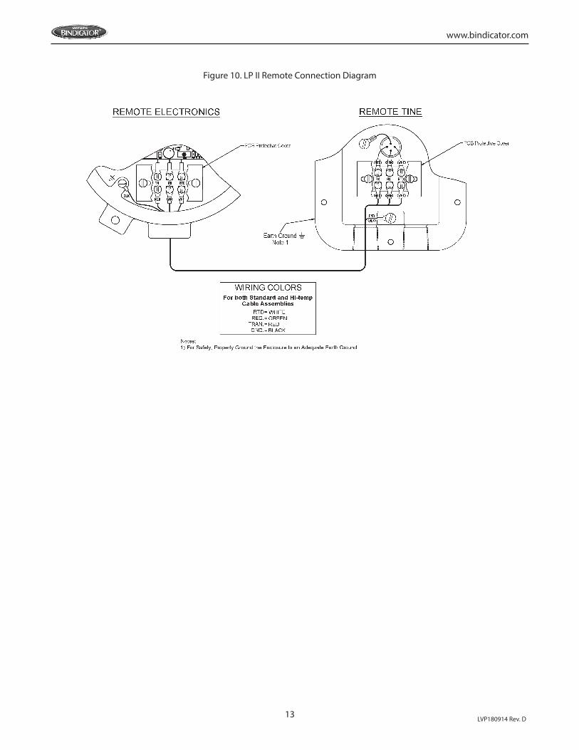
16. Refer to Figure 10 when connecting the remote rod.
17. Pull approximately 2.5” (6.35 cm) of cable through conduit and strip 3/16” (4 to 5 mm).
18. Connect factory supplied cable to terminal board as shown in Figure 10.
19. Check that all wires are held tightly in place by lightly pulling each conductor.
20. Replace cover and tighten set screw to lock cover in place.
21. Loosen the remote housing cover screws and remove cover.
22. Pull approximately 4” (10.16 cm) of cable through conduit and strip 3/16” (4 to 5 mm).
23. Connect factory supplied cable to terminal board as shown in Figure 10.
24. Check that all wires are held tightly in place by lightly pulling each conductor.
25. Reinstall the gasket, if necessary.
26. Replace cover and tighten screws to 60 in-lb (6.8 N-m) of torque.
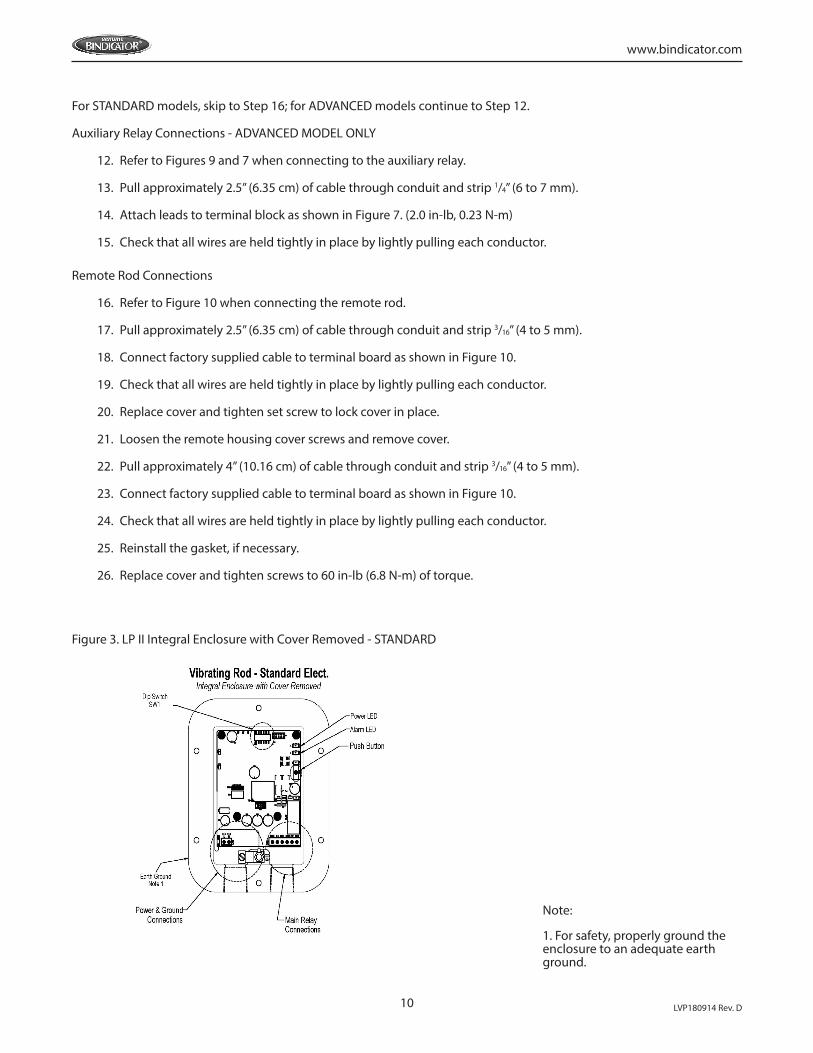
Figure 3. LP II Integral Enclosure with Cover Removed - STANDARD
Note:
1. For safety, properly ground the enclosure to an adequate earth ground.
11
www.bindicator.com
LVP180914 Rev. D
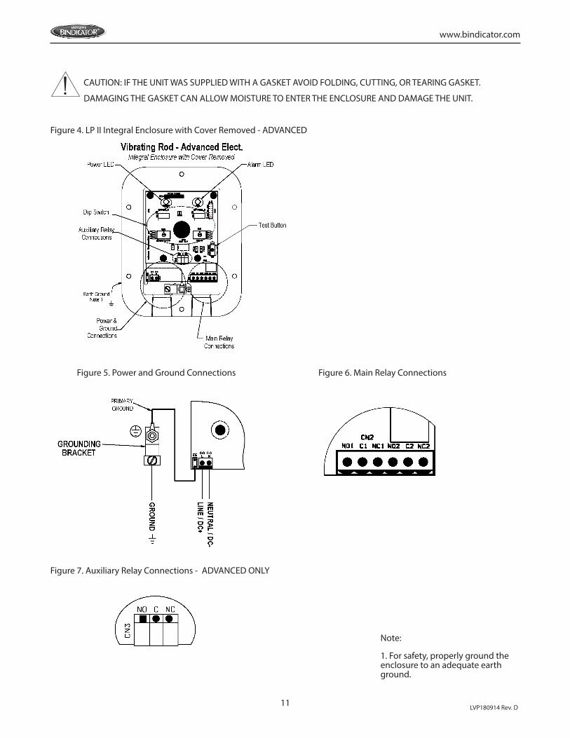
CAUTION: IF THE UNIT WAS SUPPLIED WITH A GASKET AVOID FOLDING, CUTTING, OR TEARING GASKET.
DAMAGING THE GASKET CAN ALLOW MOISTURE TO ENTER THE ENCLOSURE AND DAMAGE THE UNIT.
Figure 4. LP II Integral Enclosure with Cover Removed - ADVANCED
Figure 5. Power and Ground Connections Figure 6. Main Relay Connections
Figure 7. Auxiliary Relay Connections - ADVANCED ONLY
Note:
1. For safety, properly ground the enclosure to an adequate earth ground.
12 LVP180914 Rev. D
www.bindicator.com
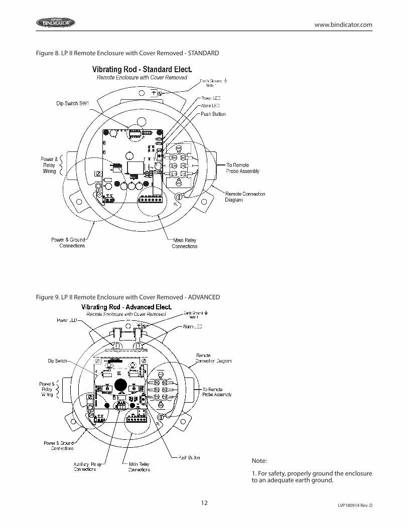
Figure 8. LP II Remote Enclosure with Cover Removed - STANDARD
Figure 9. LP II Remote Enclosure with Cover Removed - ADVANCED
Note:
1. For safety, properly ground the enclosure to an adequate earth ground.
13
www.bindicator.com
LVP180914 Rev. D
Figure 10. LP II Remote Connection Diagram
14 LVP180914 Rev. D
www.bindicator.com
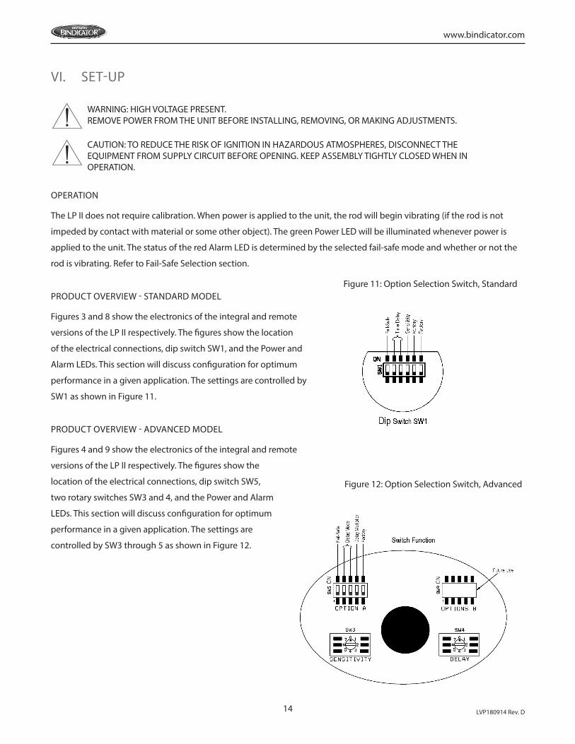
VI. SET-UP
OPERATION
The LP II does not require calibration. When power is applied to the unit, the rod will begin vibrating (if the rod is not
impeded by contact with material or some other object). The green Power LED will be illuminated whenever power is
applied to the unit. The status of the red Alarm LED is determined by the selected fail-safe mode and whether or not the
rod is vibrating. Refer to Fail-Safe Selection section.
PRODUCT OVERVIEW - STANDARD MODEL
Figures 3 and 8 show the electronics of the integral and remote
versions of the LP II respectively. The figures show the location
of the electrical connections, dip switch SW1, and the Power and
Alarm LEDs. This section will discuss configuration for optimum
performance in a given application. The settings are controlled by
SW1 as shown in Figure 11.
PRODUCT OVERVIEW - ADVANCED MODEL
Figures 4 and 9 show the electronics of the integral and remote
versions of the LP II respectively. The figures show the
location of the electrical connections, dip switch SW5,
two rotary switches SW3 and 4, and the Power and Alarm
LEDs. This section will discuss configuration for optimum
performance in a given application. The settings are
controlled by SW3 through 5 as shown in Figure 12.
Figure 11: Option Selection Switch, Standard
Figure 12: Option Selection Switch, Advanced
WARNING: HIGH VOLTAGE PRESENT.REMOVE POWER FROM THE UNIT BEFORE INSTALLING, REMOVING, OR MAKING ADJUSTMENTS.
CAUTION: TO REDUCE THE RISK OF IGNITION IN HAZARDOUS ATMOSPHERES, DISCONNECT THE EQUIPMENT FROM SUPPLY CIRCUIT BEFORE OPENING. KEEP ASSEMBLY TIGHTLY CLOSED WHEN IN OPERATION.
15
www.bindicator.com
LVP180914 Rev. D
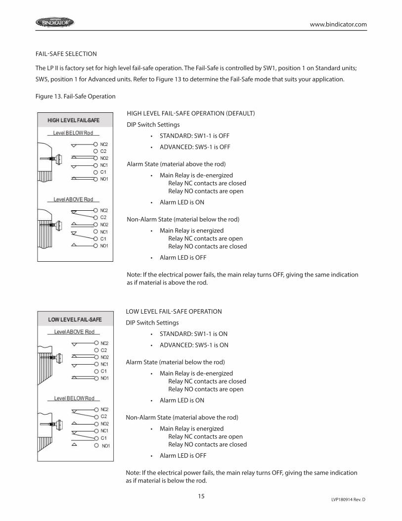
FAIL-SAFE SELECTION
The LP II is factory set for high level fail-safe operation. The Fail-Safe is controlled by SW1, position 1 on Standard units;
SW5, position 1 for Advanced units. Refer to Figure 13 to determine the Fail-Safe mode that suits your application.
Figure 13. Fail-Safe Operation
HIGH LEVEL FAIL-SAFE OPERATION (DEFAULT)
DIP Switch Settings
• STANDARD: SW1-1 is OFF
• ADVANCED: SW5-1 is OFF
Alarm State (material above the rod)
• Main Relay is de-energized Relay NC contacts are closed Relay NO contacts are open
• Alarm LED is ON
Non-Alarm State (material below the rod)
• Main Relay is energized Relay NC contacts are open Relay NO contacts are closed
• Alarm LED is OFF
Note: If the electrical power fails, the main relay turns OFF, giving the same indication as if material is above the rod.
LOW LEVEL FAIL-SAFE OPERATION
DIP Switch Settings
• STANDARD: SW1-1 is ON
• ADVANCED: SW5-1 is ON
Alarm State (material below the rod)
• Main Relay is de-energized Relay NC contacts are closed Relay NO contacts are open
• Alarm LED is ON
Non-Alarm State (material above the rod)
• Main Relay is energized Relay NC contacts are open Relay NO contacts are closed
• Alarm LED is OFF
Note: If the electrical power fails, the main relay turns OFF, giving the same indication as if material is below the rod.
16 LVP180914 Rev. D
www.bindicator.com
TIME DELAY SETTINGS - STANDARD MODEL
This setting will delay the time between when the LP II senses material and the main relay changes state. The delay is only
in this direction, regardless of fail-safe setting. There is no added delay when the material leaves the rod. Duration of the
delay is determined by SW1 positions 2, and 3 as described in the table below. The LP II is factory set for no delay.
SW1 Position 2 SW1 Position 3 Delay (seconds)OFF OFF NO DELAYOFF ON 1ON OFF 3ON ON 6
TIME DELAY SETTINGS - ADVANCED MODEL
The time between when the LP II senses material, or its absence, and the output relay changes state is field
programmable using SW5 Positions 2 and 3. The delay can be for when the product touches the rod or when the product
leaves the rod or both regardless of the fail-safe setting. The delay duration is determined by SW4 and SW5 position,
which determines if a multiplier is applied.
SW5 Position 2 Delay ModeON The selected delay by the SW4 is applied when material touches the rodOFF There is no delay when material touches the rod
SW5 Position 3 Delay ModeON The selected delay by the SW4 is applied when material leaves the rodOFF There is no delay when material leaves the rod
SW4 SW5 Position 4 Delay (seconds)0 OFF NO DELAY1 OFF 12 OFF 33 OFF 44 OFF 65 OFF 96 OFF 187 OFF 300 ON 01 ON 52 ON 153 ON 204 ON 305 ON 456 ON 907 ON 150
17
www.bindicator.com
LVP180914 Rev. D
SENSITIVITY SETTINGS - STANDARD MODEL
There are two (2) different sensitivity ranges on the LP II that can be selected using SW1 Position 4. The unit is factory set
for the lowest sensitivity. The table below is for illustration purposes, of a vertically mounted unit only, and results will
vary depending on material properties and conditions.
SW1 Position 4 Sensitivity Bulk Density (lbs/ft3)OFF High 6ON Low ≥ 9
SENSITIVITY SETTINGS - ADVANCED MODEL
The LP II provides three (3) levels of sensitivity which are selected using SW3 as shown in the table below. The unit is
factory set for the lowest sensitivity. The table below is for illustration purposes, of a vertically mounted unit only, and
results will vary depending on material properties and conditions.
SW3 Sensitivity Bulk Density (lbs/ft3)0 High 31 Medium 6
2-7 Low ≥9
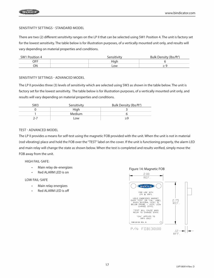
TEST - ADVANCED MODEL
The LP II provides a means for self-test using the magnetic FOB provided with the unit. When the unit is not in material
(rod vibrating) place and hold the FOB over the “TEST” label on the cover. If the unit is functioning properly, the alarm LED
and main relay will change the state as shown below. When the test is completed and results verified, simply move the
FOB away from the unit.
HIGH FAIL-SAFE:
• Main relay de-energizes • Red ALARM LED is on
LOW FAIL-SAFE
• Main relay energizes • Red ALARM LED is off
Figure 14: Magnetic FOB
18 LVP180914 Rev. D
www.bindicator.com
VII. MAINTENANCE
PREVENTATIVE MAINTENANCE
No scheduled preventative maintenance is required for the LP II Series units when properly applied and installed
correctly. There is no cleaning required for the unit before or during installation.
If the cover is removed after the unit has been in service, it is recommended to replace the gasket to prevent the ingress
of water or dust. At a minimum the gasket should be inspected for folds, cracks, and tears.
VIII. TROUBLESHOOTING
DIAGNOSTICS
The new LPII single rod has extensive built-in diagnostic routines. If any part of the electronics malfunctions, the unit will
detect the problem and indicate it by flashing the GREEN LED. The unique codes are listed in the table below.
WARNING: TO AVOID IGNITION HAZARD DUE TO ELECTROSTATIC DISCHARGE, CLEAN ONLY WITH A DAMP CLOTH.
WARNING: IN ORDER TO MAINTAIN SAFE OPERATION IN HAZARDOUS LOCATIONS, THE INTEGRITY OF THE ALUMINUM CASTING AND THE ENVIRONMENTAL SEALS MUST BE MAINTAINED. THE USER/INSTALLER MUST AVOID INSTALLATIONS WHERE AGGRESSIVE SUBSTANCES MAY BE PRESENT AND COULD AFFECT THE PERFORMANCE OF THSE MATERIALS. CARE MUST ALSO BE EXERCISED WHEN REMOVING AND REPLACING THE COVER, SO NO MARRING, SCRATCHING OR DAMAGE OCCURS TO THE FLANGES, AND THAT THE FLANGE SURFACES REMAIN COMPLETELY CLEANED OF DEBRIS.
CAUTION: IF THE UNIT WAS SUPPLIED WITH A GASKET, AVOID FOLDING, CUTTING OR TEARING THE GASKET. DAMAGING THE GASKET CAN ALLOW MOISTURE TO ENTER THE ENCLOSURE AND DAMAGE THE UNIT.
CAUTION: PROPER AND SAFE OPERATION REQUIRES THE UNIT TO BE SECURELY MOUNTED TO THE VESSEL AND WRENCH TIGHTENED. THE COVER MUST BE PROPERLY INSTALLED WHEN POWER IS APPLIED.

19
www.bindicator.com
LVP180914 Rev. D
SYMPTOM POSSIBLE CAUSE SOLUTION
The unit is notresponsive
Main relay not Functioning and Power LED is not illuminated
No power,Blown fuse
Apply proper AC/DCvoltage to the board andrecheck the unit.
If power is present andPower LED is not illuminated, then the main fuse is blown.
Replace electronics.
Main relay is functioningand Power LED is illuminated
Electronic failure, or main relay contacts are fused
Replace electronics.
Unit not as sensitive as expected
Ensure the cover is properly
torqued and unit is installed
wrench tight.
CODE CONDITION RELAYS
1 No or low excitation to the rodAux. Relay: De-energizedAlarm Relay: De-energized
2 No return signal from the piezo crystalAux. Relay: De-energizedAlarm Relay: De-energized
3 Ambient temperature greater than 75°C or less than -40°C Aux. Relay: De-energized
4 Probe RTD failureAux. Relay: De-energizedAlarm Relay: De-energized
5
Process Temperature
< -30°C
< -35°C
Standard Temp: >95°C
Standard Temp: >100°C
High Temp: >160°C
High Temp: >165°C
Aux. Relay: De-energized
Alarm Relay: De-energized
Aux. Relay: De-energized
Alarm Relay: De-energized
Aux. Relay: De-energized
Alarm Relay: De-energized
6 Factory Use Only Factory Use Only

150 Venture Boulevard Spartanburg, SC 29306Tel: (800) 778-9242 Fax: (864) [email protected]
2016 All rights reserved.All data subject to change without notice.
LVP180914 Rev. D