Embed Size (px)
Citation preview

0
Pulse-Laser Powered Orbital Launcher
Hiroshi Katsurayma1, Kimiya Komurasaki2 and Yoshihiro Arakawa21Yamaguchi University
2The University of TokyoJapan
1. Introduction
Some innovative plans in space development have been suspended because of hightransportation costs of conventional launching systems. For example, the Japanese H2Arocket will cost $400 billion to launch a 1 GW output Solar Power Satellite (SPS) whose weightis 104 ton (Collins, 1993). A pulse-laser powered orbital launcher is a potential alternative toreduce those costs: a large payload ratio can be achieved because energy is provided from aground-based laser and atmospheric air is used as a propellant.Figure 1 shows an air-breathing pulse-laser powered vehicle (“Lightcraft”) (Myrabo, 2001)with representative scales for 100 MW-class laser input. The vehicle forms plasma by focusingtransmitted laser beams using a parabolic spike nozzle. The plasma absorbs the following partof the laser pulse while expanding outward. The resulting blast wave reflects on the nozzlesurface and generates impulsive thrust.Figure 2 shows a schematic view of a pulse-laser powered launching system from the groundto a Geosynchronous Earth Orbit (GEO). In the initial stage of the launch, the vehicle closesits inlet and takes air from its rear area. This flight mode is called “pulsejet mode”. The inletis opened and air is taken from the front end of the vehicle when the vehicle is acceleratedsufficiently to be able to use ram-compression. This flight mode is called ”ramjet mode”. Theinlet is again closed and on-board hydrogen is used as a propellant when the vehicle cannotobtain sufficient air at high altitudes. This flight mode is called “rocket mode.” Through thesethree modes, the vehicle is accelerated to reach orbital velocity.Several researchers have studied the feasibility for orbital launch using several laserpropulsion systems (Toki, 1991; Kare, 1986; Humble et al., 1995; Phipps et al., 2000) , but mostof them calculate flight trajectories using the thrust modeled with a fixed energy conversionefficiency. However, in an air-breathing propulsion system, the energy conversion efficiencyevidently depends on its flight trajectory.The present article introduces our realistic performance modeling in three flightmodes: the performance in the pulsejet mode is modeled using measured energyconversion efficiency (Mori et al., 2004, a) and Computational Fluid Dynamics (CFD)analysis (Katsurayama et al., 2008); the performance during the ramjet mode is computedusing CFD analysis (Katsurayama et al., 2003); and the performance in the rocket mode isobtained analytically with the energy conversion efficiency computed using a thermochemicalequilibrium calculation (Katsurayama et al., 2003). In addition, a transfer trajectory to theGEO is proposed. The launch trajectory to its geosynchronous transfer orbit (GTO) iscomputed using these realistic thrust models. Finally, the feasibility of the pulse-laser
1
www.intechopen.com

2 Laser Pulses
Plasma
Blast Wave
Spike Nozzle
Focusing Mirror
100 MW classLaser Beam Axis of Symmetry
Liquid HydrogenTank
0.6
0m
,S~
1 m
2
1.5 m
ThrustPayload
40 kg, 0.7 m3
100 kg, 1.5 m3
Bow Shock
Inflow
Fig. 1. Air-breathing pulse-laser powered vehicle(Myrabo, 2001).
To Space
Exh
asut
Ref
ill
Laser Plasma
Blast Wave
Lase
rBea
m
Pulsejet
H2
Exh
aust
Rocket
Earth
Laser Beam (Light Highway)
Fin
e W
eath
er
Exh
aust
Inflo
w
Ram-Compression
Ramjet
Lase
rBea
m
Lase
rBea
m
Mounta
in
Fig. 2. A pulse-laser powered orbital launching system.
powered orbital launcher is discussed through estimation of its achievable payload mass perunit beam power and costs (Katsurayama et al., 2009).
2. Performance modeling of pulse-laser powered vehicle
2.1 Momentum coupling coefficient and blast wave energy conversion efficiency
Amomentum coupling coefficient Cm, which is the ratio of cumulative impulse to laser energyper pulse EL, is used as a performance indicator for laser propulsion. It is defined as
Cm =∫
I pulseFdt
/
EL, (1)
where F denotes thrust. The laser energy absorbed in a gas is converted to the blast waveenergy Ebw, which is the source energy necessary to drive an equivalent blast wave in acalorically perfect gas Ushio et al. (2008):
Ebw =∫
Vbw
[
ρ(
et+r + 1/2u2)
− ρ0
(
et+r + 1/2u2)
0
]
dV, (2)
4 Laser Pulse Phenomena and Applications
www.intechopen.com

Pulse-Laser Powered Orbital Launcher 3
where Vbw is the volume surrounded by the blast wave, and ρ and 1/2u2 are the density andkinetic energy. Subscript 0 indicates the properties before laser incidence. Here, et+r is thesum of internal translational and rotational energy. On the other hand, the vibrational andelectric excitation energy that are excited because of laser absorption are excluded from Ebwbecause they are newly stored in molecules and can not achieve pressure work as well aschemical potential energy. Because only Ebw contributes to F, Cm is proportional to the blastwave energy conversion efficiency ηbw
ηbw = Ebw/EL. (3)
Therefore, it is necessary to model the performance.
2.2 Explosion source model
According to our previous experiment (Mori et al., 2004, a;b; Mori et al., 2002) with a CO2 TEAlaser, approximately 95 % of EL is absorbed in the form of the Laser Supported Detonation(LSD) wave (Raizer, 1977), and approximately its 45 % is converted to drive a blast wave. Theremainder energy is confined in the form of chemical potential and electric excitation energyinto rarefied plasma left near the focus: it is inconvertible to thrust, and is gradually lost in theform of radiation or dissipative heat flux to the surrounding. Therefore the remainder energyis excludable to reproduce this adiabatically expanding blast wave; the energy converted tothe blast wave Ebw can be assumed to be equivalent to an instantaneous point explosionenergy necessary to drive a blast wave with the same strength.Mori et al., 2004 (a) has investigated ηbw by comparing measured shock speed with thatcalculated using a similarity solution (Kompaneets, 1960) under the assumption of ideal air.The resulting ηbw in the standard atmosphere was 0.43±0.04, which was insensitive to ELwithin the tested range of 4.0–12.8 J (Mori et al., 2004, a).Although Wang et al. (2002) has computed the propagation of a LSD wave to investigate thisenergy conversion mechanism, such a computation is too expensive for our purpose to modelther thrust performance resulting from the adiabatic expansion of the blast wave whose timescale (the order of 100 μs) are much longer than that of energy absorption process (3.5 μs). Inthe performance modeling using our CFD analyses, the blast wave is driven by a pressurizedexplosion source with ηbw=0.43, whose radius is 1mm and density is equal to that in theambient atmosphere. Such an explosion source method (Steiner et al., 1998; Jiang et al., 1998;Liang et al., 2001; 2002) is familiar to simulate blast wave propagation whose time scale ismuch longer than that of energy input process.Measured (Mori et al., 2004, a) and computed (Katsurayama et al., 2008) propagation of a blastwave in free space are compared to validate the blast wave reproducibility of this explosionsource. Figure 3 shows the histories of the shock front radius Rbw and Mach number Mbw ofthe blast wave in the case of EL=5.4J. The CFD can reproduce the measured Rbw and Mbw
after laser heating. Thereby the source model is used for computation to predict the thrustperformance, and it was located at a laser focus.
2.3 Conical laser pulsejet
The thrust generation processes in a laser pulsejet with a conical nozzle were simulated tovalidate the performacemodeling using our CFD analyses (Katsurayama et al., 2008). Figure 4schematically shows sequential thrust generation processes in the laser pulsejet with a simpleconical nozzle of its half apex angle α. In an energy absorption process (a), plasma is producednear the laser focus. The plasma absorbs laser energy in the form of a LSD wave. The large
5Pulse-Laser Powered Orbital Launcher
www.intechopen.com

4 Laser Pulses
0
2
4
6
8
10
12
14
0 1 2 3 4 5 6 7 8 9 0
5
10
15
20 0 1 2 3 4 5 6 7 8
Time t, µs (Experiment)
Shock f
ront
radiu
s R
bw,
mm
Shock f
ront
Mach n
um
ber M
bw
R bw(C
FD)
Mbw
(CF
D)
Laser heating
Adiabatic expansion
Time t, µs (CFD)
Mbw (Experiment)
R bw (E
xper
imen
t)
EL=5.4J
Fig. 3. Comparison of the CFD and the experiment on Rbw and Mbw in the explosion in freespace. (CFD: ηbw=0.43; Experiment (Mori et al., 2004, a) : ηbw=0.43±0.04)
Plasma
Laser Beam
(a) Energy Absorption process
Bla
st
wave
(b) Blast wave expansion process
(c) Exhaust process(d) Refill process
Blast wave
Axis of symmetry
α
Rn
Air
Air
Fig. 4. Schematic of a laser pulsejet engine cycle.
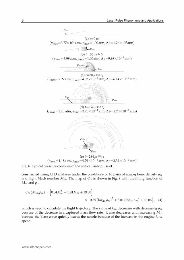
part of the absorbed energy is used to drive a high-pressure blast wave in the surrounding air.In a blast wave expansion process (b), the blast wave imparts an impulsive thrust directly to anozzle wall; thereby, main thrust is produced. In exhaust (c) and refill (d) processes, the air inthe nozzle is exhausted and fresh air is taken in. Additional thrust will be produced in theseprocesses.Because the exhaust-refill prcoesses results from an adiabatically expanding blast wave afterlaser heating, an explosion source is used to drive the blast wave instead of solving a laserabosrption process. Figures 5 and 6 respectively show the thrust history and correspondingpressure contours of a conical laser pulsejet. Δp in the captions of pressure contours showsthe interval of the contours. An explosion starts at t=0 (see Fig. 6(a)). A shock wave reachesthe nozzle exit at t0 μs as shown in Fig. 6(b). F0 is the thrust at t=t0. After t=t0, the heated airstarts to be exhausted and thrust decreases gradually. At t=t1 (see Fig. 6(c)), thrust becomeszero. Thrust becomes negative because of the rarefaction wave behind the shock wave and
6 Laser Pulse Phenomena and Applications
www.intechopen.com
Pulse-Laser Powered Orbital Launcher 5
-50
0
50
100
150
200
250
300
0 100 200 300 400 500 600
F0
t0 t1 t2 t3
Time t, µs
Thru
stF
, N
α=10o, r=0.4, EL=10J~
t4
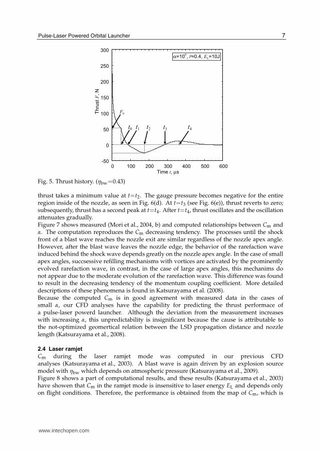
Fig. 5. Thrust history. (ηbw=0.43)
thrust takes a minimum value at t=t2. The gauge pressure becomes negative for the entireregion inside of the nozzle, as seen in Fig. 6(d). At t=t3 (see Fig. 6(e)), thrust reverts to zero;subsequently, thrust has a second peak at t=t4. After t=t4, thrust oscillates and the oscillationattenuates gradually.Figure 7 shows measured (Mori et al., 2004, b) and computed relationships between Cm andα. The computation reproduces the Cm decreasing tendency. The processes until the shockfront of a blast wave reaches the nozzle exit are similar regardless of the nozzle apex angle.However, after the blast wave leaves the nozzle edge, the behavior of the rarefaction waveinduced behind the shock wave depends greatly on the nozzle apex angle. In the case of smallapex angles, succsessive refilling mechanisms with vortices are activated by the prominentlyevolved rarefaction wave, in contrast, in the case of large apex angles, this mechanims donot appear due to the moderate evolution of the rarefaction wave. This difference was foundto result in the decreasing tendency of the momentum coupling coefficient. More detaileddescriptions of these phenomena is found in Katsurayama et al. (2008).Because the computed Cm is in good agreement with measured data in the cases ofsmall α, our CFD analyses have the capability for predicting the thrust performace ofa pulse-laser powerd launcher. Although the deviation from the measurement increaseswith increasing α, this unpredictability is insignificant because the cause is attributable tothe not-optimized geomertical relation between the LSD propagation distance and nozzlelength (Katsurayama et al., 2008).
2.4 Laser ramjet
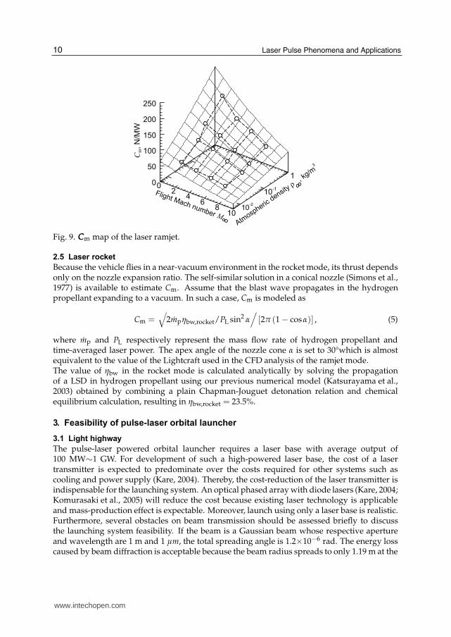
Cm during the laser ramjet mode was computed in our previous CFDanalyses (Katsurayama et al., 2003). A blast wave is again driven by an explosion sourcemodel with ηbw which depends on atmospheric pressure (Katsurayama et al., 2009).Figure 8 shows a part of computational results, and these results (Katsurayama et al., 2003)have showen that Cm in the ramjet mode is insensitive to laser energy EL and depends onlyon flight conditions. Therefore, the performance is obtained from the map of Cm, which is
7Pulse-Laser Powered Orbital Launcher
www.intechopen.com
6 Laser Pulses
pmax
(a) t=0μs(pmax=3.77×10³ atm, pmin=1.00atm, Δp=1.26×10² atm)
pmax
(b) t=50μs∼= t0(pmax=3.99atm, pmin=1.00atm, Δp=9.98×10⁻² atm)
pmax
pmin
(c) t=88μs∼= t1(pmax=2.27atm, pmin=4.32×10⁻¹ atm, Δp=6.14×10⁻² atm)
pmax
pmin
(d) t=176μs∼= t2(pmax=1.18 atm, pmin=3.70×10⁻¹ atm, Δp=2.70×10⁻² atm)
pmax
pmin
(e) t=284μs∼= t3(pmax=1.18atm, pmin=4.79×10⁻¹ atm, Δp=2.34×10⁻² atm)
Fig. 6. Typical pressure contours of the conical laser pulsejet.
constructed using CFD analyses under the conditions of 16 pairs of atmospheric density ρ∞
and flight Mach number M∞. The map of Cm is shown in Fig. 9 with the fitting function ofM∞ and ρ∞
Cm (M∞,ρ∞) =[
0.04M2∞ − 1.81M∞ + 19.00
]
×
[
0.35(
log10 ρ∞
)2+ 5.01
(
log10 ρ∞
)
+ 13.06]
, (4)
which is used to calculate the flight trajectory. The value of Cm decreases with decreasing ρ∞
because of the decrease in a captured mass flow rate. It also decreases with increasing M∞
because the blast wave quickly leaves the nozzle because of the increase in the engine flowspeed.
8 Laser Pulse Phenomena and Applications
www.intechopen.com

Pulse-Laser Powered Orbital Launcher 7
0
0.05
0.10
0.15
0.20
0.25
0.30
0.35
0.40
0.45
0 10 20 30 40 50 60 70 80
Mom
entu
m c
ouplin
g c
oeff
icie
nt C
m,
mN
s/J
Half apex angle of a conical nozzle, deg.
r=0.4, EL=10J~
CFD
Experiment
Fig. 7. Relationship between Cm and α. (CFD: ηbw=0.43; Experiment: ηbw=0.43±0.04)
(a) At t=12 μs. (pmax=2.27 atm, pmin=2.1×10⁻² atm,Δp=0.11 atm)
(b) At t= 20 μs. (pmax=4.63atm, pmin=2.1×10⁻² atm,Δp=0.23 atm)
(c) At t = 38 μs. (pmax=4.27 atm, pmin=2.0×10⁻² atm,Δp=0.21 atm)
Fig. 8. Typical pressure contours of the laser ramjet: EL=400 J, H=20 km and M∞=5.
9Pulse-Laser Powered Orbital Launcher
www.intechopen.com
8 Laser Pulses
02
46
810
10-2
10-1
10
50
100
150
200
250
Cm,
N/M
W
Flight Mach number MAtm
ospheric
density ρ
, kg
/m3
Fig. 9. CCCm map of the laser ramjet.
2.5 Laser rocket
Because the vehicle flies in a near-vacuum environment in the rocket mode, its thrust dependsonly on the nozzle expansion ratio. The self-similar solution in a conical nozzle (Simons et al.,1977) is available to estimate Cm. Assume that the blast wave propagates in the hydrogenpropellant expanding to a vacuum. In such a case, Cm is modeled as
Cm =√
2mpηbw,rocket/PL sin2 α
/
[2π (1− cosα)] , (5)
where mp and PL respectively represent the mass flow rate of hydrogen propellant andtime-averaged laser power. The apex angle of the nozzle cone α is set to 30°which is almostequivalent to the value of the Lightcraft used in the CFD analysis of the ramjet mode.The value of ηbw in the rocket mode is calculated analytically by solving the propagationof a LSD in hydrogen propellant using our previous numerical model (Katsurayama et al.,2003) obtained by combining a plain Chapman-Jouguet detonation relation and chemicalequilibrium calculation, resulting in ηbw,rocket = 23.5%.
3. Feasibility of pulse-laser orbital launcher
3.1 Light highway
The pulse-laser powered orbital launcher requires a laser base with average output of100 MW∼1 GW. For development of such a high-powered laser base, the cost of a lasertransmitter is expected to predominate over the costs required for other systems such ascooling and power supply (Kare, 2004). Thereby, the cost-reduction of the laser transmitter isindispensable for the launching system. An optical phased arraywith diode lasers (Kare, 2004;Komurasaki et al., 2005) will reduce the cost because existing laser technology is applicableand mass-production effect is expectable. Moreover, launch using only a laser base is realistic.Furthermore, several obstacles on beam transmission should be assessed briefly to discussthe launching system feasibility. If the beam is a Gaussian beam whose respective apertureand wavelength are 1 m and 1 μm, the total spreading angle is 1.2×10⁻⁶ rad. The energy losscaused by beam diffraction is acceptable because the beam radius spreads to only 1.19 m at the
10 Laser Pulse Phenomena and Applications
www.intechopen.com

Pulse-Laser Powered Orbital Launcher 9
transmission distance of 500 km, which is the typical value required for the launching system.The beam spread, attenuation, and refraction caused by nonlinear effects of the atmosphere,such as the variation of atmospheric refraction index, thermal blooming, Rayleigh, Raman andMie scattering, have been analyzed for the ORION project (Phipps et al., 1996; Cambell, 1996),which is intended to remove debris on orbits using a pulse laser. Nonlinear effects are inferredto be negligible for transmission with a beam power density under a threshold determined bya laser pulse width and wavelength.To avoid the whipping phenomenon of the beam center caused by atmospheric turbulence,the launch site should be built on the top of a mountain where the weather is expected toalways be fine and for which scintillation caused by atmosphere is small. A location where anastronomical observatory has been built is suitable if a vehicle is launched at a time withoutclouds or turbulence. For example, Mauna Kea in Hawaii has no cloud cover for 90% of thedays in a year.In addition, an ongoing study (Libeau et al., 2002) proposes a vehicle shape with which thevehicle can maintain its center axis parallel to the beam direction by generating thrust vectorand torque automatically in the direction that allows it to retain aerodynamic stability. Bothdirections of the flight and beam can be maintained as vertical to the ground using thistechnology. Therefore, vehicle tracking and beam pointing are unnecessary for the launchingsystem. The vehicle can be transferred to space along a “light highway” (Myrabo, 2001)constructed vertically from the ground, as shown in Fig. 2.
3.2 Proposed trajectory to GEO
Considering requirements for beam transmission, the vehicle is accelerated vertically in ashort distance along the light highway. Figure 10 shows a trajectory to a GEO throughthe pulse-laser powered launcher and an upper-stage propulsion system for the Hohmanntransfer. The vehicle is launched from the equator through the pulse-laser powered launcher;it is accelerated rapidly to ΔvL. The vehicle then reaches an apogee point beyond the GEOthrough inertial flight to use the ΔvL efficiently. The structure weight of laser propulsion isdetached at the apogee point, and the upper-stage propulsion system is burned. The detachedstructure is attracted to the earth and it is incinerated during reentry into the atmosphere.Figure 11 shows the variation of ΔvL and the velocity increment ΔvH required for theHohmann transfer with cut-off velocity vc, which is the flight velocity when laser propulsion isterminated. The required ΔvL and ΔvH are 18.85 and 1.84 km/s, respectively, if vc=10.6km/sis chosen.Electric propulsion is available for the upper-stage propulsion system by virtue of anabundant electricity supply from the cells if solar cells are transferred to construct an SPS.Using the Hall thruster, whose specific impulse Isp,EP is 2000 s, the transfer to the GEO takes aspiral trajectory. As a result of calculating them by solving equations of motion (Spencer et al.,1995; Kluever et al., 1998) without trajectory optimization, the effective velocity incrementΔvspiral (Spencer et al., 1995) through the upper-stage propulsion is estimated as 3.68 km/s.The resulting payload ratio λu of the upper stage is
λu = 1−∫
spiral
2ηEP (PEP/mu,0)(
gIsp,EP)2
dt
/
(1− εEP) = 0.83. (6)
where the propulsion system efficiency ηEP and the structure weight coefficient εEP areassumed respectively as 65% (Kluever et al., 1998) and 0.1. The ratio of power to the initial
11Pulse-Laser Powered Orbital Launcher
www.intechopen.com

10 Laser Pulses
Acceleration kick
Deceleration kick
Earth
GEO
GTO
ΔvL
Inert
ial f
light
apogee
perigee
Fig. 10. Proposed trajectory to GEO.
1.0
1.5
2.0
2.5
3.0
10.0 10.2 10.4 10.6 10.8 11.0 18.0
18.2
18.4
18.6
18.8
19.0
19.2
Cut-off velocity vc, km/s
Velo
city incre
ment
required
for
Hohm
ann t
ransfe
r ΔvH,
km
/s
Velo
city incre
ment
thro
ugh
puls
e laser
launcher
ΔvL,
km
/sΔvH
ΔvL
Fig. 11. Variation of the velocity increment through the pulse-laser powered launcher and thevelocity increment required for the Hohmann transfer with cut-off velocity.
upper-stage weight (PEP/mu,0) is set to 100 W/kg in view of the ratio of power to weight ofthe 1 GW-output SPS.vc=10.6km/s and λu=0.83 are used in the calculation of launch trajectories described in § 3.4.
3.3 Mode switching criteria
The pulsejet mode should be switched to the ramjet mode when the blast wave becomes freefrom propagation over the inlet because of the vehicle acceleration. However, numerous CFDanalyses are necessary to model the timing correctly because it depends on EL and flightconditions. The present model therefore chooses the safest timing: the mode is switchedwhen the flow in the vehicle is free from choking by laser heating. An engine cycle, as shown
12 Laser Pulse Phenomena and Applications
www.intechopen.com

Pulse-Laser Powered Orbital Launcher 11
Shock wave
#0 #1 #2
External compression
Isentropicexpansion
Isometricheating
#3
InletNozzle
Air
Fig. 12. Engine cycle for assessing heat-choking.
in Fig. 12, is analyzed to assess heat-choking. In this cycle, the air is taken in at location #0through an effective inlet area
A0 = Sv ×C.A.R., (7)
where Sv and C.A.R. are the maximum cross sections of the vehicle and the capture area ratio.The captured air is compressed externally from #0 to #1 as
u1 = ηdu0 (8)
where u and ηd are the flow velocity of the air and diffuser efficiency. ηd and C.A.R. areobtained using CFD analysis on the Lightcraft. With increasing M∞, ηd decreases from 0.72 to0.62 and C.A.R increases from 0.31 to 0.71 (Katsurayama et al., 2004). The air is then expandedisentropically from #1 to #2 to delay heat-choking at #3. Finally, it is laser-heated isometricallyfrom #2 to #3. The Mach number at #3 is calculated as
M3 = u3
/
√
γRT3 = u2
/
√
γR[
T2 + ηbwηtransPL/(
Cpmair
)]
Herein, T and mair is temperature and the captured mass flow rate. Respectively, R, Cp and γdenote the gas constant, the constant pressure specific heat, and the specific heat ratio of idealair. Furthermore, ηtrans is the transmission efficiency of the laser beam. The pulsejet mode isswitched to the ramjet mode when
M3 = 1. (9)
In the ramjet mode, the mass flow rate taken from the inlet decreases with altitude becauseof the decrease in the atmospheric density. Finally, the acceleration of the vehicle becomeszero because of the balance between thrust and aerodynamic drag, at the time when the flightmode is switched to the rocket mode.
3.4 Computed launch trajectory and payload ratio
A launch trajectory to the GEO is calculated by solving the following equation of motion bythe 4th order Runge-Kutta scheme.
mvdv
dt= F−
1
2ρ∞v2SvCd −mvg0 [RE/ (RE + h)]2 (10)
Therein, Sv, v and mv are the maximum cross sections of the vehicle, the flight velocity, andthe vehicle weight. Also, g0, RE and h respectively indicate the gravity acceleration on theground, the radius of the earth and the flight altitude. An aerodynamic drag coefficient Cd
is obtained using the CFD analysis on the Lightcraft; it varies from 0.15 to 0.64 depending
13Pulse-Laser Powered Orbital Launcher
www.intechopen.com
12 Laser Pulses
0
5
10
15
20
25
30
35
0 50 100 150 200 250 300 350 400 450Flight altitude h, km
Flig
ht
Mach n
um
ber M
vc=10.6 km/s λ=0.48 λ=0.35 λ=0.10
Rocke
tR
amje
t
Pulsejet
10
8
6
4
2
01 10 100
h, km (logscale)
M
PL/m
v,0=1
0.0
PL/m
v,0=5
.0
PL/m
v,0=1
.47
Ramjet
Pulsejet
Rock
et
P L/m
v,0=10
.0 M
W/k
g
P L/m
v,0=5.0
MW
/kg
P L/m
v,0=1.
47 M
W/k
g
Fig. 13. Flight Mach number vs. flight altitude.
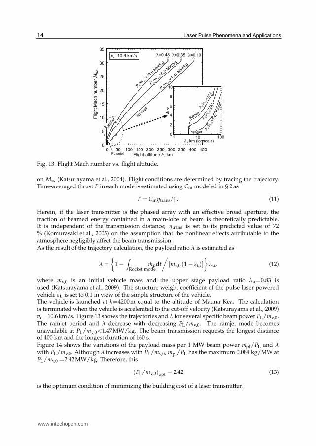
on M∞ (Katsurayama et al., 2004). Flight conditions are determined by tracing the trajectory.Time-averaged thrust F in each mode is estimated using Cm modeled in § 2as
F = CmηtransPL. (11)
Herein, if the laser transmitter is the phased array with an effective broad aperture, thefraction of beamed energy contained in a main-lobe of beam is theoretically predictable.It is independent of the transmission distance; ηtrans is set to its predicted value of 72% (Komurasaki et al., 2005) on the assumption that the nonlinear effects attributable to theatmosphere negligibly affect the beam transmission.As the result of the trajectory calculation, the payload ratio λ is estimated as
λ =
{
1−∫
Rocket modempdt
/
[mv,0 (1− εL)]
}
λu, (12)
where mv,0 is an initial vehicle mass and the upper stage payload ratio λu=0.83 isused (Katsurayama et al., 2009). The structure weight coefficient of the pulse-laser poweredvehicle εL is set to 0.1 in view of the simple structure of the vehicle.The vehicle is launched at h=4200m equal to the altitude of Mauna Kea. The calculationis terminated when the vehicle is accelerated to the cut-off velocity (Katsurayama et al., 2009)vc=10.6km/s. Figure 13 shows the trajectories and λ for several specific beam power PL/mv,0.The ramjet period and λ decrease with decreasing PL/mv,0. The ramjet mode becomesunavailable at PL/mv,0<1.47MW/kg. The beam transmission requests the longest distanceof 400 km and the longest duration of 160 s.Figure 14 shows the variations of the payload mass per 1 MW beam power mpl/PL and λwith PL/mv,0. Although λ increases with PL/mv,0, mpl/PL has the maximum 0.084 kg/MW atPL/mv,0 =2.42MW/kg. Therefore, this
(PL/mv,0)opt = 2.42 (13)
is the optimum condition of minimizing the building cost of a laser transmitter.
14 Laser Pulse Phenomena and Applications
www.intechopen.com

Pulse-Laser Powered Orbital Launcher 13
0.05
0.06
0.07
0.08
0.09
0 2 4 6 8 10 0.1
0.2
0.3
0.4
0.5
Specific beam power PL/mv,0, MW/kg
Paylo
ad m
ass p
er
unit b
eam
pow
er m
pl/P
L,
kg/M
W
Paylo
ad r
atio λ
λmpl /P
L
(PL/mv,0)opt
Ramjet is available.
(mpl/PL)max
Beam cost down Payload ratio up
Fig. 14. Variation of payload mass per unit beam power and payload ratio with specific beampower.
CLT, $/W CE, $/kWh CVP, % $/kg ηDL, %
10 0.06 1,000 40
Table 1. Costs and efficiency considered in cost estimation.
3.5 Launch cost
This section estimates the cost of the mission in which a 104-ton SPS is transferred to aGEO through many pulse-laser powered orbital launches. Although the cost estimation ofa laser transmitter with 100 MW∼1 GW-output is difficult, the most promising technologyfor high power output is to coherently couple lasers such as solid, fiber, and diodelasers (Shirakawa et al., 2002; Sanders et al., 1994). The cost of the laser transmitter can beestimated as shown in Table 1 if the coherent coupling is applicable to the array of diodelasers whose production cost per unit of power is currently the cheapest. The cost of the lasertransmitter CLT is assumed to be a current diode laser price per unit output power (Kare,2004). Other costs, such as that for the cooling system, power supply and maintenance,are not considered because they are negligibly small compared with CLT (Kare, 2004). Thegeneral electricity cost in Japan is CE. The vehicle production cost CVP is the cost per unitvehicle weight estimated for the Lightcraft whose dry mass and diameter are 100 kg and 1.4m (Richard et al., 1988). ηDL is the energy conversion efficiency of a general diode laser (Kare,2004). To compare costs of the pulse-laser powered launcher and an existing commerciallauncher, the launch cost is defined in the form of redeeming the cost of the laser transmitter.
Launch cost
Payload mass=
[
CLT/nL + (CE/ηDL) tflight
]
PL + CVPmv,0
mpl
=CLT/nL
(
mpl/PL
)
max
+(CE/ηDL) tflight(
mpl/PL
)
max
+CVP
λ(14)
For that calculation, a payload is divided and transferred through nL launchings. Furthermore,(
mpl/PL
)
max(=0.084) is used on the basis of using (PL/mv,0)opt, on the condition of which
15Pulse-Laser Powered Orbital Launcher
www.intechopen.com

14 Laser Pulses
0
20
40
60
80
100
103
104
105
Exisiting commercial launcher
Pulse
lase
r pow
ere
d la
unch
er
Launching counts nL
Launch c
ost
per
uit p
aylo
ad m
ass,
$10
3/k
g
(CLT/nL)
(PL/mpl)max
CVP/λ
The cost becomes quarterof the existing launcher.
The cost becomes lowercompared with the existing launcher.
Fig. 15. Variation of launch cost per unit payload mass with nnnL.
the resulting λ and flight time tflight are 0.20 and 112 s. The first term in the second line of Eq.(14) is the redemption of the laser transmitter. The second and third terms correspond to theelectricity and vehicle production cost. Labor costs are omitted because a generally publishedlaunch cost, e.g. $80 million per launch of the Japanese H2A rocket, includes only the rocket’sproduction cost.Figure 15 shows the variations of the launch cost per unit payload mass with nL of thepulse-laser powered orbital launcher and an existing commercial launcher. The cost of theexisting launcher is assumed to be $80 million per launch. The cost of the laser transmitter ispredominant when nL is less than 103. On the other hand, the electricity cost is negligible. Thelaunch cost decreases with increasing nL and the cost of the laser transmitter is recoveredat 3,500 launches compared with the existing launcher. The cost becomes a quarter ofthe existing launcher at nL=24,000. When nL is greater than 105, the cost of the lasertransmitter is completely recovered and the cost comprises only the vehicle production cost ofapproximately $5,000 per unit of payload mass. The electricity cost remains negligibly smallover nL=105.Consequently, if the laser base of 5 GW-class output is available, the launcher has thecapability of approximately 0.5 ton payload/launch. It is expected to deliver the 104 ton SPSthrough 24,000 launches at a quarter of the cost of an existing launcher. Moreover, if themass-production effect can reduce CVP to $100/kg, the launcher will cost about a tenth of thecurrent mode.
4. Summary
Orbital launching from the ground to a GEO using the pulse-laser powered launcheris calculated using the performance modeled in the pulsejet, ramjet and rocket modes.Consequently, it can transfer 0.084 kg payload per 1 MW beam power to the GEO. The costbecomes a quarter of that of existing systems if one can divide a single launch into 24,000
16 Laser Pulse Phenomena and Applications
www.intechopen.com

Pulse-Laser Powered Orbital Launcher 15
multiple launches. Furthermore, if the payload is transferred through 105 launches, thelaunching system can reduce the cost to the order of $103 per unit of payload mass.
5. References
Campbell, J. W. (1996). Project ORION: Orbital Debris Removal Using Ground-Based Sensorsand Lasers, NASA TM-108522
Collins, P. (1993). The Promise of Electricity from Space for World Economic Development,Proceedings of 5th International Energy Conference, Vol. 3, pp. 50-59.
Humble, W. E. and Pierson, B. L. (1995). Maximum-Payload Trajectories for a Laser-PropelledLaunch Vehicle, Journal of Guidance, Control and Dynamics, Vol. 18, No. 6,pp.1259–1266.
Jiang, Z., Takayama, K., Moosad, K. P. B., Onodera, O., and Sun, M. (1998). Numerical andExperimental Study of a micro-blast wave generated by pulsed-laser beam focusing,Shock Waves, Vol. 8, No. 6, pp.337-349.
Kare, J. T. (1986). Trajectory Simulation for Laser Launching, Proceedings of the 1986SDIO/DARPA Workshop on Laser Propulsion, Vol. 2, pp.61-77.
Kare, T. J. (2004). Modular Laser Optics for HX Laser Launch, Proceedings of the 3rd InternationalSymposium on Beamed Energy Propulsion, AIP Conference Proceedings, Vol.766, pp.128-139.
Katsurayama, H., Komurasaki, K., Momozawa, A., and Arakawa, Y. (2003). Numerical andEngine Cycle Analyses of a Pulse Laser Ramjet Vehicle, Transactions of the Japan Societyfor Aeronautical and Space Sciences, Space Technology Japan, Vol. 1, pp. 9-16.
Katsurayama, H., Ushio, M., Komurasaki, K., and Arakawa, Y. (2004). Analytical Study onFlight Performance of a RP Laser Launcher, Proceedings of 3rd International Symposiumon Beamed Energy Propulsion, AIP Conference Proceedings, Vol. 766, pp.117-127.
Katsurayama, H., Komurasaki, K., Hirooka, Y., Mori, K. and Arakawa, Y. (2008). NumericalAnalyses of Exhaust and Refill Processes of a Laser Pulsejet, Journal of Propulsion andPower, Vol. 24, No. 5, pp.999-1006.
Katsurayama, H., Komurasaki, K., and Arakawa, Y. (2009). A Preliminary Study ofPulse-Laser Powered Orbital Launcher, ACTA Astronautica, Vol. 65, No. 7-8,pp.1032-1041.
Kompaneets, A. S. (1960). A point explosion in an inhomogeneous atmosphere, Soviet PhysicsDoklady, Vol. 5, No. 1, pp.46-48.
Komurasaki, K., Nakagawa, T., Ohmura, S., and Arakawa, Y. (2005). Energy Transmission inSpace Using an Optical Phased Array, Transactions of the Japan Society for Aeronauticaland Space Sciences Space Technology Japan, Vol. 3, pp. 7-11.
Liang, S.-M., Hsu, J.-L.,, and Wang, J.-S. (2001). Numerical Study of Cylindrical Blast-WavePropagation and Reflection, generated by pulsed-laser beam focusing, AIAA Journal,Vol. 39, No. 6, pp.1152-1158.
Liang, S.-M., Wang, J.-S., and Chen, H. (2002). Numerical Study of Spherical Blast-WavePropagation and Reflection, generated by pulsed-laser beam focusing,” Shock waves,Vol. 12, No. 1, pp.59-68.
Libeau, M. A. and Myrabo, L. N. (2002). Combined Theoretical and Experimental FlightDynamics Investigation of a Laser-Propelled Vehicle, AIAA Paper 2002-3781.
Mori, K., Komurasaki, K., and Arakawa, Y. (2002). Influence of the Focusing f Number onHeating Regime Transition in Laser Absorption Waves, Journal of Applied Physics,Vol.92, No.10, pp.5663-5667.
17Pulse-Laser Powered Orbital Launcher
www.intechopen.com
16 Laser Pulses
Mori, K., Komurasaki, K., and Arakawa, Y. (2004). Energy Transfer from a Laser Pulse to aBlast Wave in Reduced-Pressure Air Atmospheres, Journal of Applied Physics, Vol. 95,No. 11, pp. 5979-5983.
Mori, K., Komurasaki, K., and Arakawa, Y. (2004). Nozzle Scale Optimum for the ImpulseGeneration in a Laser Pulsejet, Journal of Spacecraft and Rockets, Vol. 41, No. 5, pp.887-889.
Myrabo, L. N. (2001). World Record Flights of Beam-Riding Rocket Lightcraft: Demonstrationof “Disruptive” Propulsion Technology, AIAA Paper 2001-3798.
Phipps, C. R., Reilly, P. R., and Campbell, J. W. (2000). Optimum Parameters for LaserLaunching Objects into Low Earth Orbit, Laser and Particle Beams, Vol. 18, pp.661-695.
Phipps, C. R., Friedman, H., Gavel, D., Murray, J., Albrecht, G., George, E. V., Ho,C., Priedhorsky, W., Michaelis, M. M., and Reilly, J. P. (1996). ORION: ClearingNear-Earth Space Debris Using a 20-kW, 530-nm, Earth-Based, Repetitively PulsedLaser, Laser Particle Beams, Vol. 14, pp. 1-4.
Steiner, H., Gretler,W., and Hirschler, T. (1998). Numerical Solution for Spherical Laser-DrivenShock Waves, Shock Waves, Vol. 8, No. 3, pp.139-147.
Toki, K. (1991). Conceptual Study of Laser Direct Launch, The Journal of Space Technology andScience, Vol. 8, No. 2, 1991, pp. 23-31.
Wang, T.-S., Chen, Y.-S., Liu, J., Myrabo, L. N., and Mead, F. B. Jr. (2002). AdvancedPerformance Modeling of Experimental Laser Lightcraft, Journal of Propulsion andPower, Vol. 18, No. 6, pp. 1129-1138.
Spencer, D. B. and Robert, D. C. (1995). Designing Continuous-Thrust Low-Earth-Orbit toGeosynchronous-Earth-Orbit Transfers, Journal of Spacecraft and Rockets, Vol. 32, No.6, pp.1033-1038.
Kluever, C. A. and Oleson, S. R. (1998). Direct Approach for Computing Near-OptimalLow-Thrust Earth-Orbit Transfers, Journal of Spacecraft and Rockets, Vol. 35, No. 4,pp.509-515.
Sedov, L. I. (1993). Similarity and Dimensional Methods in Mechanics, 10th Ed., CRC Press, BocaRaton.
Raizer, Y. P. (1977). Laser-Induced Discharge Phenomena, Consultants Bureau, New York andLondon.
Richard, J. C., Morales, C., and Myrabo, L. N. (1988) Transatmospheric Laser Propulsion of a100 MW-Class Lightcraft Technology Demonstrator (LTD), AIAA Paper 88-2970.
Sanders, S., et al. (1994). High Power Coherent Two-Dimensional Semiconductor Laser Array,Applied Physics Letters,, Vol. 64, No. 12, pp.1478-1480.
Simons, G. A. and Pirri, A. N. (1977). The Fluid Mechanics of Pulsed Laser Propulsion, AIAAJournal, Vol. 15, No. 6, pp. 835-842.
Shirakawa, A., Saitou, T., Sekiguchi, T., and Ueda, K. (2002). Coherent Addition of Fiber Lasersby Use of a Fiber Coupler, Optics Express, Vol. 10, No. 21, pp.1167-1172.
Ushio, M., Komurasaki, K., Kawamura, K., and Arakawa, Y. (2008). Effect of Laser SupportedDetonation Wave Confinement on Termination Conditions, Shock Waves, Vol. 18,No.1, pp.35-39.
18 Laser Pulse Phenomena and Applications
www.intechopen.com
Laser Pulse Phenomena and ApplicationsEdited by Dr. F. J. Duarte
ISBN 978-953-307-405-4Hard cover, 474 pagesPublisher InTechPublished online 30, November, 2010Published in print edition November, 2010
InTech EuropeUniversity Campus STeP Ri Slavka Krautzeka 83/A 51000 Rijeka, Croatia Phone: +385 (51) 770 447 Fax: +385 (51) 686 166www.intechopen.com
InTech ChinaUnit 405, Office Block, Hotel Equatorial Shanghai No.65, Yan An Road (West), Shanghai, 200040, China
Phone: +86-21-62489820 Fax: +86-21-62489821
Pulsed lasers are available in the gas, liquid, and the solid state. These lasers are also enormously versatile intheir output characteristics yielding emission from very large energy pulses to very high peak-power pulses.Pulsed lasers are equally versatile in their spectral characteristics. This volume includes an impressive array ofcurrent research on pulsed laser phenomena and applications. Laser Pulse Phenomena and Applicationscovers a wide range of topics from laser powered orbital launchers, and laser rocket engines, to laser-matterinteractions, detector and sensor laser technology, laser ablation, and biological applications.
How to referenceIn order to correctly reference this scholarly work, feel free to copy and paste the following:
Hiroshi Katsurayma, Kimiya Komurasaki and Yoshihiro Arakawa (2010). Pulse-Laser Powered OrbitalLauncher, Laser Pulse Phenomena and Applications, Dr. F. J. Duarte (Ed.), ISBN: 978-953-307-405-4,InTech, Available from: http://www.intechopen.com/books/laser-pulse-phenomena-and-applications/pulse-laser-powered-orbital-launcher