Embed Size (px)
Citation preview

Experiment P-8 Pulley System Ver 3.3.3
1
Experiment P-8
Pulley System
Objectives To learn about pulley systems: fixed, movable and compound
pulleys. To measure the effort force and the load force. To measure the distance the force sensor has to be pulled in
order to move the load 10 cm and calculate the velocity ratio. To calculate the mechanical advantage of each system. To find the relationship between the mechanical advantage and
the velocity ratio.
Modules and Sensors PC + NeuLog application
USB-200 module
NUL-211 Force sensor
Equipment and Accessories
35 cm track 1
Track leg 2
20" rod 2
Track rider 2
Boss head 2
100 g slotted mass 2
Slotted mass hanger 1
Rod with pulley (perpendicular)
1
Pulley with hook 1
Thread (~1m) 1
3 m measuring tape 1
The items above are included in the NeuLog Mechanics kit,
MEC-KIT and also in the NeuLog Pulley kit, PUL-KIT.
Experiment P-8 Pulley System Ver 3.3.3
2
Introduction A pulley is a grooved wheel firmly attached to an axle. A rope or a cable fits into the groove and passes over the wheel. A fixed pulley is fastened to one spot. The fixed pulley has no gains in force or distance, but it changes the direction of the force. A movable pulley moves along a rope. It decreases the force, but the rope must be pulled for a longer distance. A compound pulley (also known as a block and a tackle) is the combination of fixed and movable pulleys. The fixed pulley changes the direction of the force and the movable pulley decreases the applied force. In this experiment, you will study these three types of pulley systems. You will use a force sensor to measure the effect of each type of pulley on the force that must be applied to perform work. You will also find the velocity ratio of each system.
Experiment P-8 Pulley System Ver 3.3.3
3
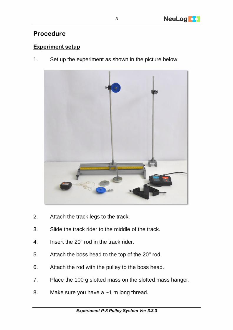
Procedure Experiment setup 1. Set up the experiment as shown in the picture below.
2. Attach the track legs to the track.
3. Slide the track rider to the middle of the track.
4. Insert the 20" rod in the track rider.
5. Attach the boss head to the top of the 20'' rod.
6. Attach the rod with the pulley to the boss head.
7. Place the 100 g slotted mass on the slotted mass hanger.
8. Make sure you have a ~1 m long thread.

Experiment P-8 Pulley System Ver 3.3.3
4
Sensor setup
9. Connect the USB module to the PC.
10. Connect the Force sensor to the USB-200 module.
Note:
The following application functions are explained in short. It is recommended to practice the NeuLog application functions (as described in the user manual) beforehand.
11. Run the NeuLog application and check that the force sensor is identified.

Experiment P-8 Pulley System Ver 3.3.3
5
Settings
1. Click on the On-line Experiment icon in the NeuLog main icon bar.
2. Click on the Sensor's Module box.
3. Click on the Range button and change the range to +/- 10 N. 4. Click on the Push=Negative button to get positive values
when hanging the cart from the force sensor's hook.
5. Click on the Experiment Setup icon and set the:
Experiment duration to 10 seconds Sampling rate to 10 per second

Experiment P-8 Pulley System Ver 3.3.3
6
Testing and measurements
Note:
The orientation of the sensor is very important. Before each measurement, hold the sensor in the same orientation you will use for the specific experiment and zero it.
12. Sensor Zeroing: hold the sensor in the proper orientation (the hook should be facing downwards for the first measurements) and press the button in the sensor’s box for about 3 seconds.
Alternatively, you can click on the Reset button in the sensor's module box menu.
13. When using a pulley, the rope is 'pulled' on the effort side; the weight lifted on the other side is called the 'load'. This is a fixed pulley:
Force sensor 'Effort'
Weight 'Load'

Experiment P-8 Pulley System Ver 3.3.3
7
Measure the Load force: Put a 100 g on the mass holder and then hang these on the force sensor.
14. Click on the Run Experiment icon to start the measurement.
15. In order to focus on the desired range, click on the Zoom
icon , locate the mouse cursor at a point above the graph and press its left button; keep it pressed and create a rectangle that includes the whole range.

Experiment P-8 Pulley System Ver 3.3.3
8
16. Your graph should be similar to the following:
17. Click on the Show Functions icon and then click on the Force button on the left of the screen.
18. Insert the average value you see in the menu on the following
table.
No pulley
Measured force (with mass holder) [N]
Measured force [N] (with mass holder and movable pulley)
100 g (sample experiment)
1.024 1.19
100 g
200 g

Experiment P-8 Pulley System Ver 3.3.3
9
19. Add another 100 g slotted mass (you will now have 200 g)
and click on the Run Experiment icon again (without erasing the previous graph).
20. Insert the new data to the table above.
21. Make a measurement with the 100 g mass together with the movable pulley and with the 200 g mass together with the movable pulley.
22. Insert the values in the previous table.
For some pulley setups we include the pulley with the load force because it is directly attached to the load and moves with the load.
23. Set up the experiment as shown in the following picture.
24. Remember to zero the sensor in this new orientation, with the
hook facing upwards before putting on any load.
25. This is a fixed pulley. Hang a 100 g slotted mass on it. The length of the thread is not important.

Experiment P-8 Pulley System Ver 3.3.3
10
26. In order to measure the effort force, click on the Run
Experiment icon to start the measurement. 27. Your graph should be similar to the following:
28. Repeat the measurement with a 200 g slotted mass (without erasing the first graph).
29. Save your graph.
30. Write the average force values in the following data table.
Fixed pulley
Slotted mass
Load force (N) (without a movable pulley)
Effort force (N)
Mechanical advantage (Load/Effort)
Distance moved by the effort [cm] (Distance moved by load is 10 cm)
Velocity ratio
100 g (sample experiment)
1.024 1.019 ~1
100 g
200 g
The ratio of the Load to the Effort (Load/Effort) is called the Mechanical Advantage (MA) of a pulley system. A system with MA>1 decreases the effort (Effort<Load) while a pulley system with MA<1 increases the effort (Effort>Load).

Experiment P-8 Pulley System Ver 3.3.3
11
31. Calculate the Mechanical Advantage (MA) for each mass and
write it in the previous table.
32. Lift the load 10 cm up. What distance did you have to move the force sensor in order to lift the load? Insert the distance value in the table above. The velocity ratio is equal to the distance moved by the effort divided by the distance moved by the load. Calculate the velocity ratio and insert the data in the previous table.

Experiment P-8 Pulley System Ver 3.3.3
12
33. Assemble a second system as shown in the following picture.
34. This is a movable pulley. Put the sensor in place with the right orientation (without the slotted mass) and zero it again.
35. Click on the Erase Graph icon .
36. Hang a 100 g slotted mass and click on the Run Experiment
icon to start the measurement. 37. Repeat the measurement with two 100 g slotted masses
without erasing the first measurement.
Experiment P-8 Pulley System Ver 3.3.3
13
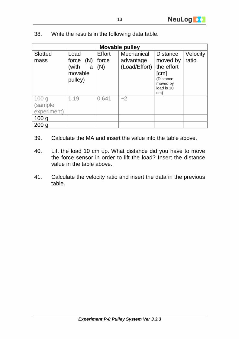
38. Write the results in the following data table.
Movable pulley
Slotted mass
Load force (N) (with a movable pulley)
Effort force (N)
Mechanical advantage (Load/Effort)
Distance moved by the effort [cm] (Distance moved by load is 10 cm)
Velocity ratio
100 g (sample experiment)
1.19 0.641 ~2
100 g
200 g
39. Calculate the MA and insert the value into the table above.
40. Lift the load 10 cm up. What distance did you have to move
the force sensor in order to lift the load? Insert the distance value in the table above.
41. Calculate the velocity ratio and insert the data in the previous
table.

Experiment P-8 Pulley System Ver 3.3.3
14
42. Assemble a third system as shown in the following picture.
43. This is a compound pulley system. Put the sensor in place
with the right orientation and zero it again (without the slotted mass).
44. Click on the Erase Graph icon .
45. Hang a 100 g slotted mass and click on the Run Experiment
icon to start the measurement. 46. Repeat the measurement with two 100 g slotted masses
without erasing the first measurement.

Experiment P-8 Pulley System Ver 3.3.3
15
47. Write the results in the following data table.
Compound pulley
Slotted mass
Load force (N) (with a movable pulley)
Effort force (N)
Mechanical advantage (Load/Effort)
Distance moved by the effort [cm] (Distance moved by load is 10 cm)
Velocity ratio
100 g
200 g
48. Calculate the MA and insert the value into the table above.
49. Lift the load 10 cm up. What distance did you have to move
the force sensor in order to lift the load? Insert the distance value in the table above.
50. Calculate the velocity ratio and insert the data in the previous
table.
Summary questions 1. Which system decreased the effort? Explain what causes the
effort to decrease.
2. What is the advantage of using the pulley that does not decrease the effort over just lifting the weight without a pulley?
3. What is the advantage of the compound pulley over the
movable pulley?
4. What is the connection between the mechanical advantage and the velocity ratio?
5. What force do you have to exert to lift a 70 Kg weight using a
system with a mechanical advantage of 3?