Embed Size (px)
Citation preview
VOLUME 20, 1958/59, No. 8 pp. 209-244.lfJR'-/
Published 23th March 1959
Philips Technical ReviewDEALING WITH TECHNICAL PROBLEMS
RELATING TO THE PRODUCTS, PROCESSES AND INVESTIGATIONS OFTHE PHILIPS INDUSTRIES
THE. SCINTILLATION COUNTER
by J. A. W. van der DOES de BYE. 621.387.464
The scintillation counter - the most efficient gamma-ray counter now available - isfinding ever-increasing application in medicine and industry as well as in physics. Inmany hospitals, its use in conjunction with radioisotopes ("tracers") has become a partof routine diagnostic practice.A description is given below of the scintillation counter marketed some time àgo by
Philips. The article briefly discusses the physical principles underlying the operation. ofa scintillation counter, and the disturbing effects of inherent noise and background radi-ation which must be reckoned with both by the designer and by the user of such equipment.
The method of measuring the intensity of high-energy radiation by means of the scintillation effect,i.e. the property of some substances to emit flashesof light when exposed to such radiation, is one of theearliest known to nuclear physics. The method orig-inally consisted in counting the number of scintil-lations produced by a particles incident on a zinc-sulphide screen; the observer viewed the screenunder a magnifying glass or microscope and countedthe scintillations visually. With the development ofthe Geiger-Müller counter in the thirties, which,with electronic scalers, made it possible to countvery many more particles (quanta) per second andwas moreover suitable for detecting fJ and y ra-diation, the scintillation method fell into disuse.In the last ten years, however, in, conjunction withthe photomultiplier tube, it has acquired a new leaseof life as the scintillation counter, which is now animportant and widely used monitoring instrumentin the :6.eldsof nuclear physics and medicine.
The following remarks will serve to define roughlythe position of the scintillation counter in relationto the other types of radiation detectors. As is known,the quanta and particles emitted by radioactivesubstances give rise to ionization and excitation intheir passage through matter. The operation ofthe hitherto most widely used radiation detectors,viz. the ionization chamber, the proportional counterand the Geiger-Müller counter, is based solelyon the ionization effect. These instruments areideally suited for the detection of charged particles
- the Geiger tube counts every charged particle -but not for the' detection of, gamma rays.Owing-to their high penetrating power, there is aconsiderable chance of the gamma quanta passingright through the detector without causing anyionization, or excitation. In the Geiger counter thechance of an incident y-quantum being countedis, within a wide energy range, of the order ofmagnitude of only 1%.
Since the chance of a y-quantum being absorbedincreases with the total mass of the absorbingmedium, appreciable improvement in the situationcould only be obtained by using instruments con-taining a substantial quantity of liquid or solidmatter as detector. Attempts to construct ion-ization chambers :filled with a liquid or solidproved successful in principle, but failed to leadto instruments that could be produced and usedon a large scale 1). A great step forward wasmade with the advent of the photomultiplier tubewhich, being a much more rapid detector than thehuman eye, made it possible to revert to the oldscintillation method, i.e. to a method of detectionbased not on the accumulation of liberated chargesbut on the localized luminescence caused in somesubstances by ionization and excitation. (The ordi-nary photoelectric cell is also fast, but fo.r other rea-
i) A discussion of the properties of various materials thatcan be used in an ionization chamber of the crystal-countertype is given by F. C. Champion, Progr. nucI. Phys. 3, 159-176, 1953.
210 PHILIPS TECHNICAL REVIEW VOLUJ\1E 20
sons is unsuitable.) Provided they are optically trans-parent, seintillating materials of relatively largevolume can he used without impairing the detecta-bility of the light flashes, enabling a gamma-raycounter to be built that can count a high percentageof the incident quanta, even of very hard radiations(high quantum counting efficiency).A scintillator at present commonly used is sodium
iodide, activated with a small amount (about 1%)of thallium. For some years now it has been pos-sible t? make single crystals of this substance, thusmeeting the two requirements of transparency andlarge maes. The fact that Nal is extremely hygro-scopic, however, entails special measures in mount-ing the crystal.
In regard to its "dead 'time", i.e. the time whichmust elapse after a count before the next quantumcan he counted, the scintillation counter is far supe-rior to the Geiger counter and is roughly on a parwith the proportional counter. The dead time ofa scintillation counter 2) fitted with an NaI(TI)crystal is at most 2-}[Lsec.Finally, it is also possiblewith the scintillation method to measure the energyof the incident quanta, that is to say to constructscintillation spectrometers.
lts high quantum counting efficiency for gammarays makes the scintillation counter very suitablefor applications involving the use of only smallquantities of radioactive material. This is particu-larly the case where the material is administeredto a patient for medical purposes, the object usuallybeing to study the patient's metabolism. The prop-erty of some chemical compounds to concentratein certain tissues mayalso be exploited; the tissuesthen become radiation sources and are as such detec-table. With a narrow collimator, through which thescintillator "sees" only a small part of the object ata time, the size and shape of such tissue·s can bedetermined by scanning the object point by point.
Monitoring for radioactive contamination of theground and of the human body also involves onlyslight amounts of radioactivo material, and sein-tillation counters are therefore often employed inequipment for this purpose 3).
Scintillation counters are sometimes used insteadof Geiger counters for the measurements on liquidsamples ·occurring in medical and biological prac-
2) A forthcoming article in this Reviewwill deal with problemsconcerning the dead time of a scintillation counter in moredetail than is possible here, and will also explain the rea-sons for the value mentioned above. For the dead time ofthe proportional counter .see P. H. Dowling, C. F. Hendee,T. R. KohIer and W. Parrish, Philips tech. Rev. 18, 262-275, 1956/57.
~) See e.g. A. Nemet, R. B. Stephens and W. A. Bayfield,Philips tech. Rev. 16, 201-210, 1954/55.
tice. The scintillation counters designed for suchwork often have a hollowed-out (well-type) crystalinto which a test tube .fits, so that a very large frac-tion of the total emitted y radiation enters thecrystal. Moreover, the position of the sample withrespect to the crystal is ~ot nearly so critical aswhen a flat crystal is used.
Many industrial applications are a variant ofradiography with X-rays, being similarly based onthe locally varying attenuation suffered by a beamof gamma rays in passing through an inhomoge-neous body. The non-destructive testing of mate--rials, as for example the .detection of .flaws in cast-ings and controlling the thickness of sheet metal ina rolling mill, are often carried out with gamma rays,for which purposes the object is scanned with ascintillation counter. Prospecting for uranium oreswith a portable scintillation counter is a familiarexample of the geological applications.
In the following pages we shall describe thescintillation counter developed and marketed byPhilips, and discuss the physical principles under-lying its operation. We shall then consider disturb-ing effects, such as noise and background radia-tion, and conclude by touching brieflyon the prop-erties of seintillating materials other than NaI(TI),the detecting of radiations other than gammaradiation, and scintillation speetrometry ..
Description of the scintillation counter
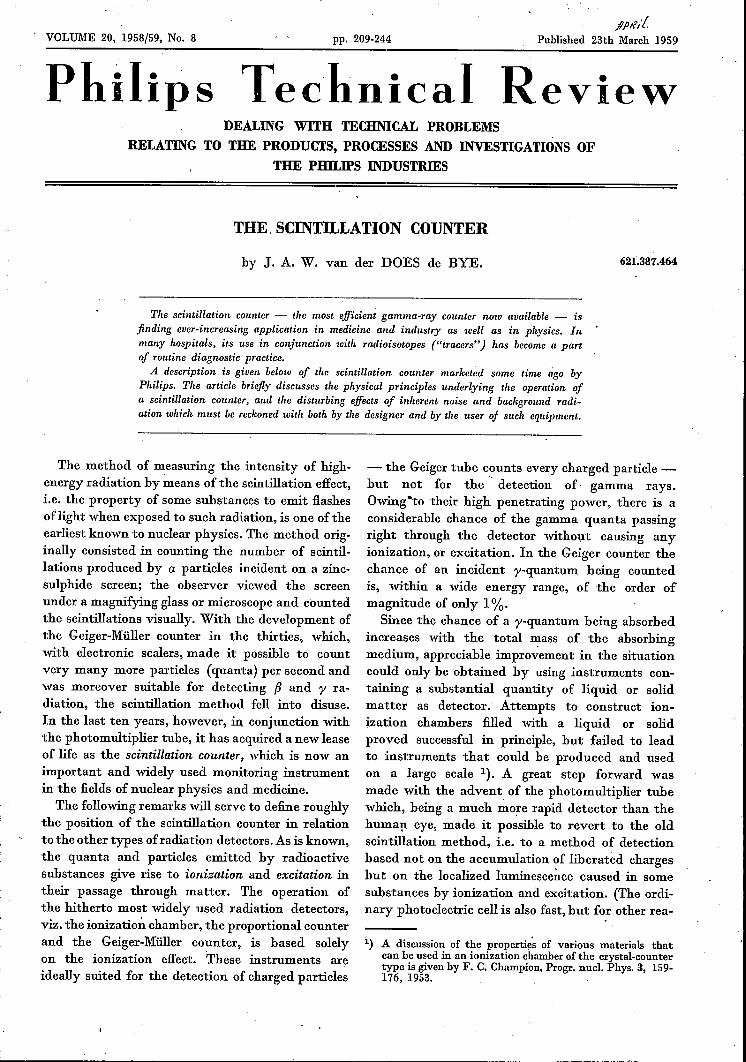
The seintillating material, in the shape of a cubeor cylinder, is mounted with one of its flat faces ingood optical contact with the window of a photo-multiplier tube, behind which is situated the photo-cathode. The electrons released from the photo-cathode by a light flash are attracted to a secondary-emitting electrode (dynode) which is maintainedat a certain positive potential (about 150 V) withrespect to the cathode. Each electron impinging onthis dynode liberates a number of secondary elec-trons, which in their turn travel to the next dynode,and so on (fig. 1). The number of dynodes, i.e, thenumber of times this process is repeated, is about '10 in most commercially available photomulti-plîer tubes. This gives a tube gain of between 1 and10 million times, making it possible to detect sein-tillations that liberate only one electron from thephotocathode.
The current pulses at the output of the photo-multiplier give rise to voltage pulses across theanode load. These are passed through a suitablydesigned amplifier, and the amplified pulses are fedvia a pulse-height discriminator - a circuit presetto pass only those pulses that exceed a certain
1958/59, No. 8 SCINTILLATION COUNTER N, V. PHllIPS' GLOEll.t~F£M·, RIEKtf
~
..2 5
5
• 6
p
I
H l 96002
Fig. 1. Example of the way in which an NaI(TI) crystal (K)can be mounted on the photomultiplier tube (P) in a scirrtil-lation counter. The crystal is hermetically sealed in a holder,which completely prevents the penetration of water vapour.1 aluminium sleeve, 2 glass base, 3 aluminium cap cementedto the sleeve, 4 thin film of transparent viscous fluid, 5 rubberring, 6 reflecting layer of MgO between aluminium wall andcrystal, 7 fluid film as 4. The two Huid films improve the op-tical contact between the crystal, the glass base and the tubewindow. The rubber ring separates the fluid from the MgO,which serves to increase the reflection from the walls.
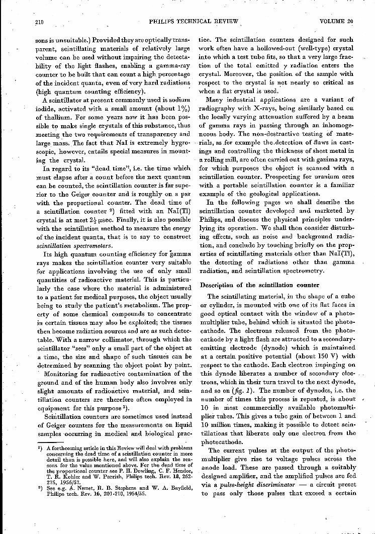
height - to a scaling circuit. Each stage of thelatter divides the number of pulses it receives by acertain factor - in the present instance 10. This isconveniently achieved by the use of decade scalertubes 4), from which the number of counted pulsesin units, tens, hundreds, etc., can be read directly,each tube delivering one digit of this number. Ablock diagram of the arrangement is given in jig. 2.A photograph of the complete Philips scintillationcounting equipment is shown in jig. 3. The counteris fitted with an NaI(Tl) crystal, which is mounted
PMc
A
I----------_j
960,03
Fig. 2. Block diagram of a scintillation counter layout.S scintillator, PM photomultiplier tube, CF pre-amplifier, Apulse amplifier, D discriminator, C counting unit. Scintillator,photomultiplier tube and pre-amplifier are mounted togetherin a "probe".
4) See e.g. A. J. W. M. van Overbeek, J. L. H. Jonker andK. Rodenhuis, Philips tech. Rev. 14, 313-326, 1952/53.
3
together with the multiplier tube [Philips 50 AVP)and the first amplifying stage (cathode-followercircuit) to form a probe. The latter is connected by acable to the rack containing the rest of the equip-ment. This consists of a power pack which suppliesthe high tension for the multiplier tube (for 10 dy-nodes, about 1500 V), a pulse amplifier and a count-ing unit fitted with decade scaler tubes, which alsofunctions as a fixed-level (non-variable) discrimi-nator. The equipment allows the counting rate, i.e.the average number of quanta detected per unittime, to be determined either from the number ofquanta counted within a given time, or from thetime taken for the number of counts to reach a pre-setvalue, e.g. 10000 5).The chance that the counter will register a gamma
quantum entering the crystal is about 50% for quan-ta of 500 keY, 35% for quanta of 1 MeV and 25%for quanta of 2 MeV. In the case of soft gamma andX-ray quanta (10-50 keV) the chance is almost100%. These values relate to a cylindrical crystal2.5 cm in diameter and 2 cm in height. Crystals ofother dimensions can also be mounted.
Processes occurring in the scintillation material
Before discussing the properties of the scintil-lation counter, we shall briefly review the processesthat occur inside the scintillator. These are of twokinds, the first being the absorption of gamma quan-ta, which takes place in three ways, and the secondthe emission oflight (the actual scintillation process).
Absorption. of gamma rays
When a beam of mono-energetic gamma quantapasses through a layer of matter of thickness d,the intensity I (d) of the emergent beam is given,as for X-rays, by the formula
(1)
where I(O) is the intensity of the incident beam,(l the density of the material and a the mass atten-uation coefficient. If the product (la is large, thematerial is strongly absorbent. The mass attenua-tion coefficient depends on the chemical composi-tion of the absorber (but not on its state of aggre-gation) and on the energy Eo of the incident gammaquanta.The absorption of the gamma quanta may in-
volve three distinct processes: the photo-electriceffect, the Compton effect and pair production. Theprobability of these processes taking place varies
5) Cf. W. Parrish, Philips tech. Rev. 17, 206-221, 1955/56.
212 PHILlPS TECHNICAL REVIEW VOLUME 20
with Eo, but differently in each case. Each processhas its own mass attenuation coefficient, definedrespectively as af, ac and ap; the value of a is thesum of the three. During these processes the energyof the gamma quantum is either wholly or partlyconverted into the kinetic energy of one or moreelectrons. If, then, a beam of mono-energetic gammaquanta is absorbed, the energy spectrum of theseelectrons is not mono-energetic (monochromatic),but fairly complex and partly continuous.
Since only the total electron energy is important forthe scintillation process, we shall assume that weare concerned with a single electron of energy Eo-The photo-electric effect thus produces in the elec-tron energy spectrum a mono-energetic peak 6). Thephoto-electric effect makes a large contribution tothe absorption when Eo is smaller than 200 keV;the absorption of soft and moderately hardX-radiation is almost entirely due to this effect.In this case, then, a ~ Ol'
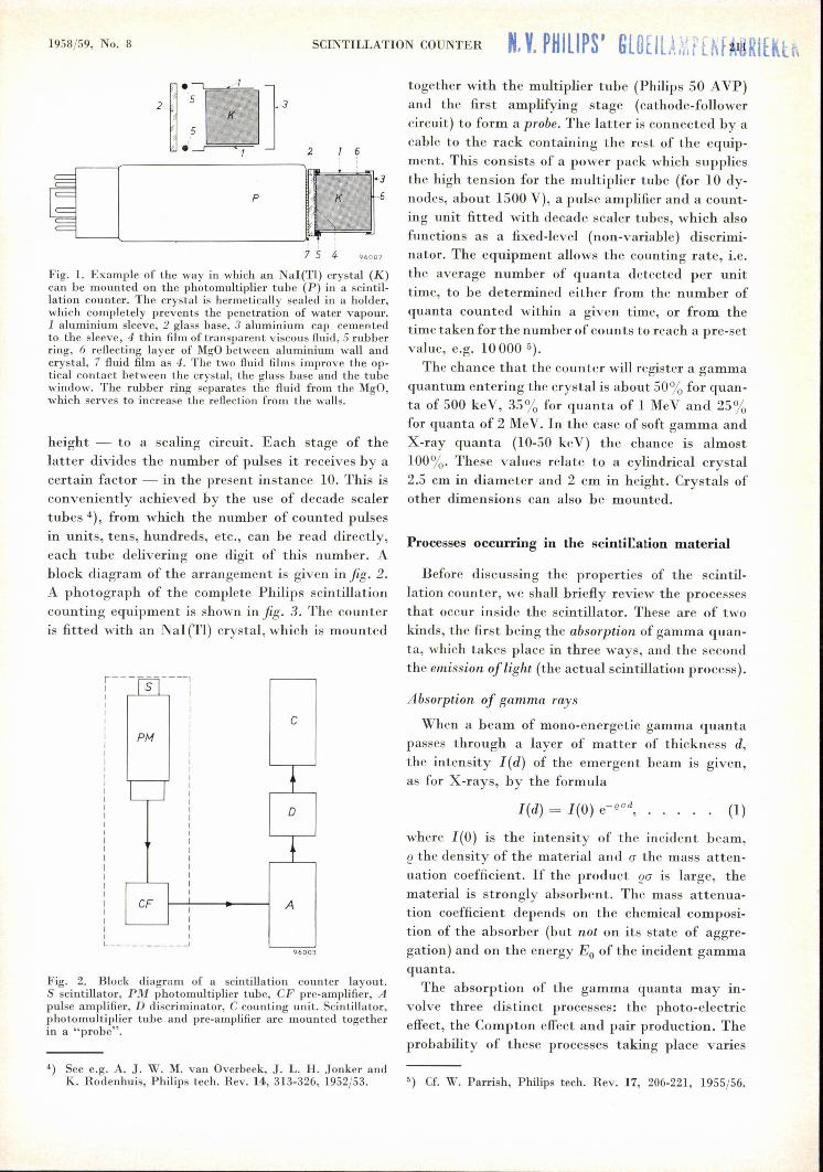
Fig. 3. The Philips scintillation counter in use. The upper part of the probe projects abovea lead shield ("castle") at the bottom of which the radioactive specimen is situated. Theprobe is connected by a cable to the cabinet containing the rest of the electronic equip-ment. The bottom unit contains on the left the power pack for the photomultiplier tube(and to which a Geiger counter can also be connected) and on the right the pulse ampli-fier. The top unit contains the counting circuit, which also functions as pulse-height dis-criminator. The middle panel is fitted with a clock which indicates the time in which theapparatus has counted a pre-determined number of pulses.
The apparatus was developed to the production stage under the direction of Mr. A. Mooy.
In the first of the three processes - the photo-electric effect - an electron (usually a K electron)is ejected from its shell by the gamma quantum.The latter is thereby completely absorbed, i.e. theenergy of the photo-electron is equal to the gammaenergy minus the electron binding energy. When theelectron configuration returns to its normal state- which it does in a very short time - the bindingenergy in question is emitted in the form of X-rayquanta or Auger electrons, or both. Any X-ray quan-ta emitted are in turn absorbed in their immediatesurroundings, so that the quantum energy Eo isentirely converted into electron kinetic energy.
In the second of the three processes - the Comp-ton effect - a y-quantum collides with an electronto which it transfers only a part Ec of its energy.It then continues on its way in a different direction(scattering) with an energy E' = Eo - Ec. For agiven direction of electron and scattered gammaquantum, it is possible to calculate Ec and E' bytreating the gamma quantum as a particle having6) In small crystals the X-ray quanta which "carry off" the
binding energy Eb may nevertheless escape. In that casea residual "escape peak" is found beside the main photo-electric peak. If Eo is of the order of 1 MeV or more, thenEo ~ Eb and the two peaks virtually coincide. This subjectis dealt with at greater length on pp. 269-270 of the articlequoted in 2).
1958/59, No. 8 SCINTILLATION COUNTER 213
a kinetic energy Eo (and E' after the collision) anda momentum Eo/c (or E'/c), and by applying tothe collision' process the laws of conservation ofenergy and momentum. The energy Ec transferred tothe electron in this collision may have' any valuebetween 0 and Eo/(l + Er/2Eo), where Er is theenergy corresponding to the rest mass of an electron,viz. 0.51 MeV. The spectrum of the Ec values isthus continuous, and the larger Eo the larger themaximum value of Ec/Eo; at Eo = 2 MeV thisamounts to 0.80, and at 10 MeV to 0.977. Theprobability that a certain value of Ec will occur is afunction of Ec and of Eo. With increasing Eo therelatively small values of Ec decrease in significaneeand the energy spectrum of the Compton electronsacquires more the character of a peak.
There is of course a chance that the scatteredgamma quantum will be absorbed. If it is absorbedby the photo-electric effect, this again is a case of theentire energy Eo being converted into electron kineticenergy; outwardly this is not to be distihgüishedfrom the direct occurrence of the photo-electric ef-fect. Naturally, the chance of this happening in-creases according to the quantity of material used.With increasing seintillater size, therefore, the"photo-electric peak" becomes larger at the expenseof the Compton continuum 7).The probability of a Compton collision, like the
probability of photo-electric absorption, decreaseswith increasing Eo, but it does so in a much less pro-nounced way. In an NaI(Tl) crystal the probabilityof a Compton collision is already greater thanthat of the photo-electric effect at an Eo value of0.5 MeV.The third process - pair production - occurs
only when Eo :2:: 1.02MeV. The chance of this occur-ring increases with increasing Eo. Where Eo is of theorder of 10 MeV or more, pair production pre-dominates over the other two effects. The processconsists in the conversion of a gamma quantum intotwo particles which are identical except for theirsign, namely an electron and a positon. The kineticenergy ofthe pair is Eo-1.02 MeV (i.e. Eoless 2Er'the energy equivalent of the rest mass of thecreated particles). Thus, besides the "photo-peak"in the electron energy spectrum there may be a "pairpeak", which is outwardly identical with the photo-peak caused by gamma quanta having an energyEo - 1.02MeV. This pair peak is superimposed onthe Compton continuum. .
7) The name "photo-electric peak" is really not applicablein this case; one should speak rather of a "peak of completeabsorption".
The average life of a positon is very,.. short. Itunites with an electron and the consequent anni-hilation of the pair gives rise to the emission of twoidentical but oppositely directed (conservation ofmomentum) gamma quanta each having an energyof 0.51 MeV. Generally this annihilation occurswhen the positon has lost its kinetic energy; some-times, however, also when it is in motion.
Naturally there is a certain chance that one orboth annihilation quanta will be absorbed in thescintillator . If both are absorbed, then the entireEo is ~gain absorbed and the photo-peak becomeslarger at the expense of the pair peak. The cases,however, where only one of the annihilation quantais absorbed give the appearance of a third peakin theelectron energy spectrum, its position being exactlymidway between the photo-peak (corresponding tothe absor-ption of Eo) and the pair peak (absorption .of Eo -1.02 MeV). In the absorption of gammaquanta by pair production the photo-peak will thusbe .relatively larger when a scintillator of largermass is used,just as was the case with the Comptoneffect.
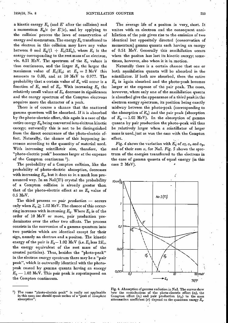
.'Fig.4 shows the variation with Eri of Ol, ac and ap,
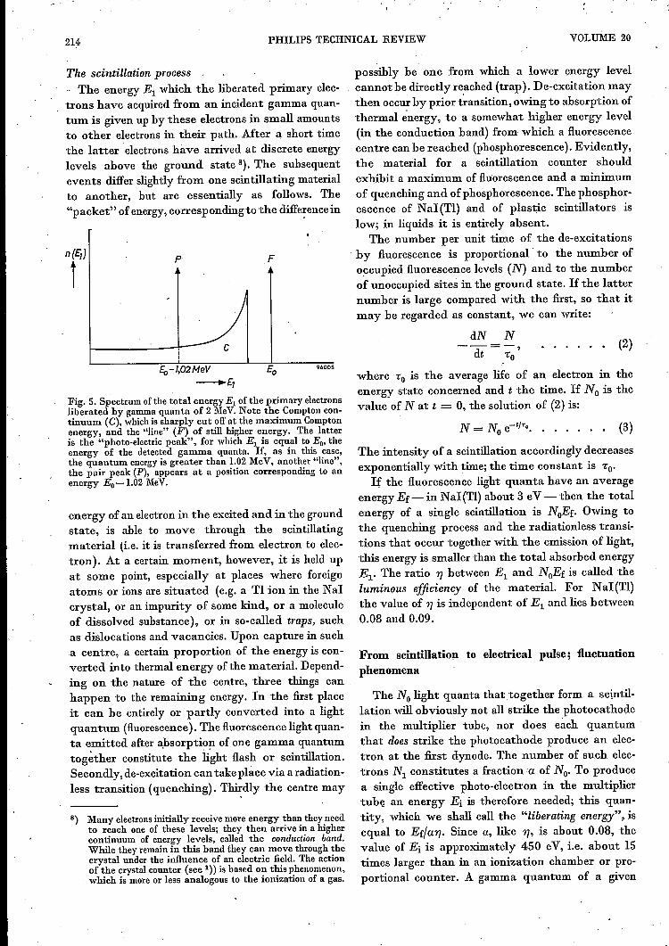
and of rheir sum a, for Nal. Fig. 5 shows the spec-trum of the energies transferred to the electrons inthe case of gamma quanta of equal energy (in thiscase 2 MeV). ~.
0,0
~
-
NaI(n)
1\({\
ffc-·-\..~~
\ .................~\
\ ,/<, ~.,
\ ........... '\ ../<,\T
\ .I <,Of\ /rfp "
"\\ / .'\
1 'L
0,1
0,000,1 10 l00MeV
Fig. 4. Absorption ofgamma radiation in Nal. The curves showhow the contributions of the photo-electric effect (af), theCompton effect (ac) and pair production (Gp) to the massattenuation coefficient (a) depend on the quantum energy Eo.
214 PHILlPS TECHNICAL REVIEW VOLUME 20
The scintillation process. The energy El which the liberated primary elec-trons have acquired from an incident gamma quan-tum is given up by these electrons in small amountsto other electrons in their path. After a short timethe latter electrons have arrived at discrete energylevels above the ground state 8). The suhsequentevents differ slightly from one scintillating materialto another, hut are essentially as follows, The"packet" of energy, correspondingto the diffe~encein
n(E,)
ip F
96005Er,-1,02MeV___"'£1
Fig. 5. Spectrum ofthe total energy El of the primary electronsliberated by gamma quanta of 2 MeV.Note the Compton con-tinuum (C), whichis sharply cut offat the maximum Comptonenergy, and the "line" (F) of still higher energy. The latteris the "photo-electric peak", for which El is equal to Eo, theenergy of the detected gamma quanta. If, as in this case,the quantum energyis greater than 1.02MeV, another "line",the pair peak (P), appears at a position corresponding to anenergy Eo-1.02 MeV.
energy of an electron in the excited and in the groundstate, is ahle to move through the seintillatingmaterial (i.e, it is transferred from electron to elec-tron). At a certain moment, however, it is held upat some point, especially at places where foreignatoms or ions are situated (e.g. a Tl ion in the NaIcrystal, or an impurity of some kind, or a moleculeof dissolved substance), or in so-called traps, suchas dislocations and vacancies. Upon capture in sucha centre, a certain proportion of the energy is con-verted into thermal energy of the material. Depend-ing on the nature of the centre, three things canhappen to the remaining energy. In the first placeit can he entirely or partly converted into a lightquantum (fluorescence). The fluorescence light quan-ta emitted after absorption of one gamma quantumtogether constitute the light flash or scintillation.Secondly, de-excitation can take place via a radiation-less transition (quenching). Thirdly the centre may
8) Many electronsinitially receive more energy than they needto reach one of these levels; they then arrive in a highercontinuum of energy levels, called the conduction band.While they remain in this band they can move through thecrystal under the influence of an electric field. The actionof the crystal counter (see 1» is based on this phenomenon,
. which is more or less analogous to the ionization of a gas.
possibly be one from which a lower energy levelcannot he directly re.ached (trap). De-excitation maythen occur by prior transition, owing to ahsorption ofthermal energy, to a somewhat higher energy level(in the conduction hand) from which a fluorescencecentre can be reachedjphosphorescence). Evidently,the material for a scintillation counter shouldexhibit a maximum of fluorescence and a minimumof quenching and of phosphorescence. The phosphor-escence of NaI(TI) and of plastic scintillators islow; in liquids it is entirely absent.
The number per unit time of the de-excitations'by fluorescence is proportional' to the number ofoccupied fluorescence levels (N) and to the numberof unoccupied sites in the ground state. If the latternumber is large compared with the first, so that itmay he regarded as constant, we can write:
dN N(2)--= ,"0dt
where "0 is the average life of an electron in theenergy state concerned and t the time. If No is thevalue of Nat t = 0, the solution of (2) is:
N = No e-I/'<o. . . . . . . (3)
The intensity of a scintillation accordingly decreasesexponentially with time; the time constant is "0'
If the fluorescence light quanta have an averageenergy Ef-in NaI(TI) ahout 3 eV -then the totalenergy of a single scintillation is NoEf. Owing tothe quenching process and the radiationless transi-tions that occur together "with the emission of light,this energy is smaller than the total ahsorbed energyEl' The ratio 'Yj between El and NoEf is called theluminous efficiency of the material. For NaI(TI)the value of 'Yj is independent of El and lies between0.08 and 0.09.
From scintillation to electrical pulse; fluctuationphenomena
The No light quanta thattogether form a seintil-lation will obviously not all strike the photocathodein the multiplier tuhe, nor does each quantumthat does strike the photocathode produce an elec-tron at the first dynode. The number of such elec-trons Nl constitutes a fraction a of No. To producea single effective photo-electron in the multipliertube an energy Ei is therefore needed; this quan-tity, which we shall call the "liberating energy", isequal to Ef/a'Yj. Since a, like 'Yj, is ahout 0.08, thevalue of Ei is approximately 450 eV, i.e. about 15times larger than in an ionization chamber or pro-portional counter. A gamma quantum of a given
1958/59, No. 8 SCINTILLATION COUNTER 215
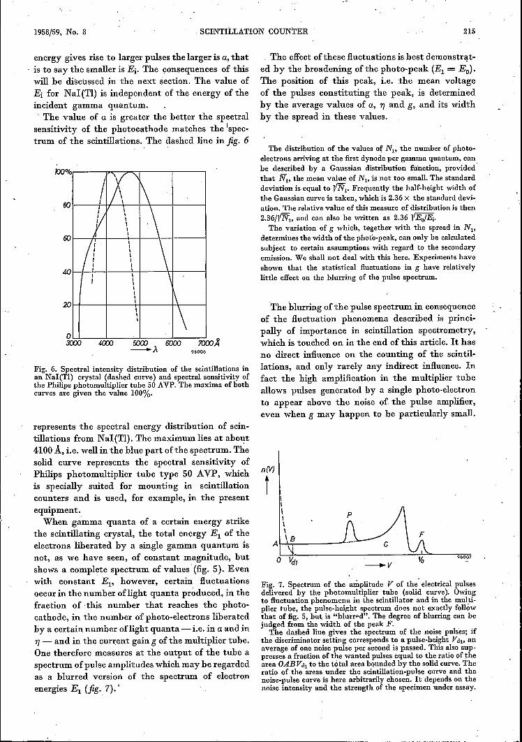
energy gives rise to larger pulses the larger is a, thatis to say the smaller is Ei. The çonsequences of thiswill be discussed in the next section. The value ofEi for NaI(TI) is independent of the energy of theincident gamma quantum., The value of a is greater the better the spectralsensitivity of the photocathode matches the 'spec-trum of the scintillations. The dashed line in fig. 6
~%~----~~~~------~----~IX'~801----+-I+-+-H,---__~I---__~
Y \ \ro~_,~+--+-4--+-4---~
11 \ \~ 1 \ \
111
2O~--+--~\4---44-\-__I
'\OLL-~~-~J_--~--~3000 4WJ 5000 6000 7000~
-À 96006
Fig. 6. Spectral intensity distribution of the scintillations inan NaI(TI) crystal (dashed curve) and spectral sensitivity ofthe Philips photomultiplier tube 50 AVP. The maxima of bothcurves are given the value 100%.
represents the spectral energy distribution of sein-tillations from NaI(TI). The maximum lies at about4100 A, i.e. well in the blue part of the spectrum. Thesolid curve represents the spectral sensitivity ofPhilips photomultiplier tube type 50 AVP, whichis specially suited for mounting in scintillationcounters and is used, for example, in the presentequipment.When gamma quanta of a certain energy strike
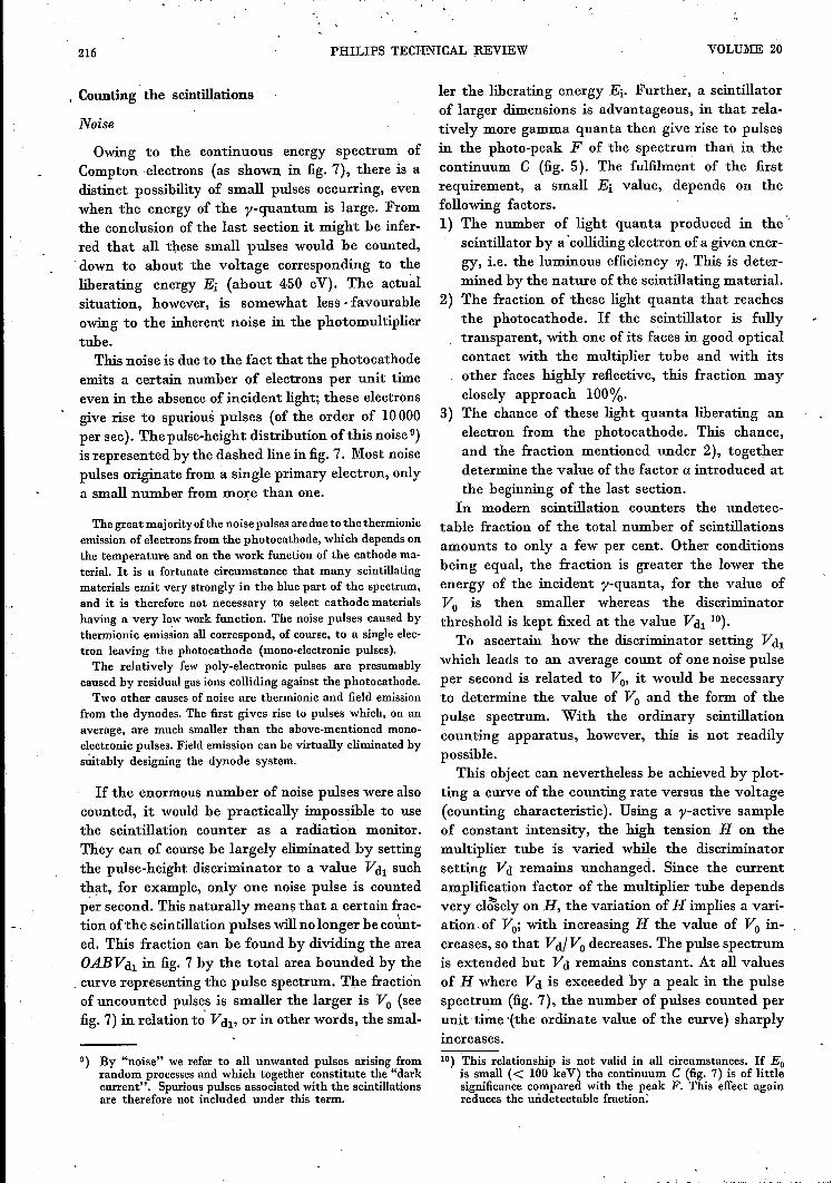
the scintillating crystal, the total energy El of theelectrons liberated by a single gamma quantum isnot, .as we have seen, of constant magnitude, butshows a complete spectrum of values' (fig. 5). Evenwith constant El' however, certain fluctuationsoccur in the number oflight quanta produced, in thefraction of this number that reaches the photo-cathode, in the number of photo-electrons liberatedby a certain number oflight quanta -- i.e. in a and in17-- and in the current gain g of the multiplier tube.One therefore measures at the output of the tube aspectrum of pulse amplitudes which may be regardedas a blurred version of" the spectrum of electronenergies El (fig. 7). •
The effect of these fluctuations is best demonatrat-ed by the broadening ofthe photo-peak (El = Eo).The position of this peak, i.e, the mean voltageof the pulses constituting the peak, is determinedby the average values of a, 17and g, and its widthby the spread in these values.
The distribution of the values of NI' the number of photo-electrons arriving at the first dynode per gamma quantum, canbe described by a Gaussian distribution function, providedthat N;., the mean value of NI' is not too small. The standarddeviation is equal to 1!N;.. Frequently the half-height width ofthe Gaussian curve is taken, which is 2.36X the standard devi-ation. The relative value of this measure of distribution is then2.36/J!N;.,and can also be written as 2.36 l/Eo/Ei.The variation of g which, together with the spread in NI>
determines the width of the photo-peak, can only be calculatedsubject to certain assumptions with regard to the secondaryemission. We shall not deal with this here. Experiments haveshown that the statistical fluctuations in g have relativelylittle effect on the blurring of the pulse spectrum.
The blurring of the pulse spectrum in consequenceof the fluctuation phenomena described is princi-pally of importance in scintillation spectrometry,which is touched on in the end of this article. It hasno direct influence on the counting of the seintil-lations, and only rarely any indirect influence. Infact the high amplification in the multiplier tubeallows pulses generated by a single photo-electronto appear above the noise of the pulse amplifier,even when g may happen to be particularly small.
n(V}
Î
96007
\I\I\\
'aA \,
Fig. 7. Spectrum of the amplitude V of the electrical pulsesdelivered by the photomultiplier tube (solid curve). Owingto fluctuation phenomena in the scintillator and in the multi-plier tube, the pulse-height spectrum does not exactly followthat of fig. 5, but is "blurrpd". The degree of blurriug can bejudged from the width of the peak F.The dashed line gives the spectrum of the noise pulses; if
the discriminator setting corresponds to a pulse-height Vdu anaverage of one noise pulse per second is passed. This also sup-presses a fraction of the wanted pulses equal to the ratio of thearea OABVdI to the total area bounded by the solid curve. Theratio of the areas under the scintillation-pulse curve and thenoise-pulse curve is here arbitrarily chosen. It depends on thenoise intensity and the strength of the specimen under assay.
216 PHILIPS TECHNICAL ~EVIEW VOLUME 20
, Counting the scintillations
Noise
Owing to the continuous energy spectrum ofCompton 'electrons (as shown in fig. 7), there is adistinct possibility of small pulses occurring, evenwhen the energy of the y-quantum is large. Fromthe conclusion of the last section it might be infer-red that all these small pulses would be counted,down to about the voltage corresponding to theliberating energy Ei (about 450 eV). The actualsituation, however, is somewhat less· favourableowing to the inherent noise in the photomultipliertube.
This noise is due to the fact that the photocathodeemits a certain number of electrons per unit timeeven in the absence of incident light; these electronsgive rise to spurious pulses (of the order of 10000per sec). The pulse-height distribution of this noise 9)is represented by the dashed line in fig. 7. Most noisepulses originate from a single primary electron, onlya small number from more than one.
The great maj orityofthe noise pulses are due to the thermionicemission of electrons from the photocathode, which depends onthe temperature and on the work function of the cathode ma-terial. It is a fortunate circumstance that many seintillatingmaterials emit very strongly in the blue part of the spectrum,and it is therefore not necessary to select cathode materialshaving a very low work function. The noise pulses caused bythermionic emission all correspond, of course, to a single elec-tron leaving the photocathode (mono-electronic pulses).The relatively few poly-electronic pulses are presumably
caused by residual gas ions colliding against the photocathode.Two other causes of noise are thermionic and field emission
from the dynodes. The first gives rise to pulses which, on anaverage, are much smaller than the above-mentioned mono-electronic pulses. Field emission can be virtually eliminated bysuitably designing the dynode system.
If the enormous number of noise pulses were alsocounted, it would be practically impossible to usethe scintillation counter as a radiation monitor.They can of course be largely eliminated by settingthe pulse-height discriminator to a value Vdl suchthat, for example, only one noise pulse is countedper second. This naturally means that a certain frac-tion of the scintillation pulses will no longer be count-ed. This fraction can be found by dividing the areaOABVdl in fig. 7 by the total area bounded by the. curve representing the pulse spectrum. The fractionof uncounted pulses is smaller the larger is Vo (seefig. 7) in relation to' Vdl' or in other words, the smal-
9) By "noise" we refer to all unwanted pulses arising fromrandom processes and which together constitute the "darkcurrent". Spuriouspulses associated with the scintillationsare therefore not included under this term.
Ier the liberating energy Ei, Further, a scintillatorof larger dimensions is advantageous, in that rela-tively more gamma quanta then give rise to pulsesin the photo-peak F of the spectrum than in thecontinuum C (fig. 5). The fulfilment of the firstrequirement, a small Ei value, depends on thefollowing factors.1) The number of light quanta produced in the'
scintillator by a 'colliding electron of a given ener-gy, i.e. the luminous efficiency 'YJ. This is deter-mined by the nature of the seintillating material.
2) The fraction of these light quanta that reachesthe photocathode. If the scintillator is fullytransparent, with one of its faces in good opticalcontact with the multiplier tube and with itsother faces highly reflective, this fraction mayclosely approach 100%.
3) The chance of these light quanta liberating anelectron from the photocathode. This chance,and the fraction mentioned under 2), togetherdetermine the value of the factor a introduced atthe beginning of the last section.In modern scintillation counters the undetec-
table fraction of the total number of scintillationsamounts to only a few per cent. Other conditionsbeing equal, the fraction is greater the lower theenergy of the incident y-quanta, for the value ofVo is then smaller whereas the discriminatorthreshold is kept fixed at the value Vdl 10).
To ascertain how the discriminator setting Vdlwhich leads to an average count of one noise pulseper second is related to Vo' it would he necessaryto determine the value of Vo and the form of thepulse spectrum. With the ordinary scintillationcounting apparatus, however, this is not readilypossible.
This object can nevertheless be achieved by plot-ting a curve of the counting rate versus the voltage(counting characteristic). Using a y-active sampleof constant intensity, the high tension H on themultiplier tube is varied while the discriminatorsetting Vd remains unchanged. Since the currentamplification factor of the multiplier tube dependsvery cl~sely on H, the variation of H implies a vari-ation.of Vo; with increasing H the value of Vo in-creases, so that Vd/Vo decreases. The pulse spectrumis extended but Vd remains constant. At all valuesof H where Vd is exceeded by a peak in the pulsespectrum (fig. 7), the number of pulses counted perunit time ,(the ordinate value of the curve) sharplyincreases.10) This relationship is not valid in all circumstances. If Eo
is small « 100 keV) the continuum C (fig. 7) is of littlesignificanee compared with the peak F. This effect againreduces the uridetectable fraction:
1958/59, No. 8I
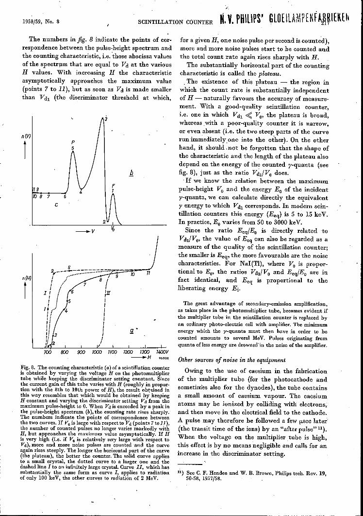
SCINTILLATION CÓUNTER N. V. PUlUPS' GLOEILAMPENfA~~IEK[~The numbers in fig. 8 indicate the points of cor-
respondence between the pulse-height spectrum andthe counting characteristic, i.e. 'those abscissa valuesofthe spectrum that are equal to Vd at the variousH values. With increasing H the characteristicasymptotically approaches the maximum value(points 7 to 11), but as soon as Vd is made smallerthan Vdl (the discriminator threshold at which,
n(V)
1
F119
TO 8 7 6
c
-v
n(H)
t2 Ö - -- -- - - --7-";r..~~~-~:-,--:-::'f"------ .-.-................. 10 711 ,.-" / 9I ~ 8 If ,... I
I I ! 'llI : II ! II : I
1+ ..... I': IIf ,I i ,I: I11 1 s:li 1I' Jli 2~ I
700 800 900 1000 1100 1200 1300 1400V-H 96006
Fig.8. The counting characteristic (a) of a scintillation counteris obtained by varying the voltage H on the photomultipliertube while keeping the discriminator setting constant. Sincethe current gain of this tube varies with H (roughly in propor-tion with the 8th to 10th power of H), the result obtained inthis way resembles that which would be obtained by keepingH constant and varying the discriminator setting Vd from themaximum pulse-height to O.When Vd is exceeded by a peak inthe pulse-height spectrum (b), the counting rate rises sharply.The numbers indicate the points of correspondence betweenthe two curves. If Vo is large with respect to Vd (points 7 to 11),the number of counted pulses no longer varies markedly withH, but approaches the maximum value asymptotically. If His very high (i.e, if Vo is relatively very large with respect toVd), more and more noise pulses are counted and the curveagain rises steeply. The longer the horizontal part of the curve(the plateau), the better the counter. The solid curve appliesto a small crystal, the dotted curve to a larger one and thedashed line I to an infinitely large crystal. Curve 11,which hassubstantially the same form as curve I, applies to radiationof only 100 keY, the other curves to radiation of 2 MeV.
for a given H, one noise pulse per second is counted),more and more noise pulses start to be counted andthe total count rate again rises sharply with H.
The substantially horizontal part of the countingcharacteristic is called the plateau.. The existence of this plateau - the region in
which the count rate is substantially independentof H - naturally favours the accuracy of measure-ment. With a good-quality scintillation counter,i.e. one in which Vdl ~ Vo' the plateau is broad,whereas with a poor-quality counter it is narrow,or even absent (i.e. the two steep parts of the curverun immediatelyone into the other). On the otherhand, it should .not be forgotten that the shape ofthe characteristic and the length of the plateau alsodepend on the energy of the counted y-quanta (seefig. 8), just as the ratio VdliVo does ..If we know the relation between the maximum
pulse-height Vo and the energy Eo of the incidenty-quanta, we can calculate directly the equivalenty energy to which Vdl corresponds. In modern sein-tillation counters this energy (Eeq) is 5 to 15 keV.In practice, Eo varies from 50 to 3000 keV.
Since the ratio EeqlEo is directly related toVdIl Vo' the value of Eeq can also be regarded as ameasure of the quality of the scintillation counter;the smaller is Eeq, the more favourable are the noisecharacteristics. For NaI(TI), where Vo is propor-tional to Eo, the ratios VdliVo and EeqlEo are infact identical, and Eeq is proportional to theliberating energy Ei,
The great advantage of secondary-emission amplification,as takes place in the photomultiplier tube, becomes evident ifthe multiplier tube in the scintillation counter is replaced byan ordinary photo-electric cell with amplifier. The minimumenergy which the y-quanta must then have in order to hecounted amounts to several MeV. Pulses originating fromquanta ofless energy are drownedin the noise of the amplifier.
Other sources of noise in the equipment
Owing to the use of caesium in the fabricationof the multiplier tube (for the photocathode andsometimes also for the dynodes), the tube containsa small amount of caesium vapour. The caesiumatoms may be ionized by colliding with electrons,and then move in the electrical field to the cathode.A pulse may therefore be followed a few fLseclater'(the transit time of the ions) by an "after pulse" 11).When the voltage on the multiplier, tube is high,this effect is by no means 'negligible and calls for anincrease in the discriminator setting.
11) See C. F. Hendee and W. B. Brown, Philips tech. Rev. 19,50-58, 1957/58.
218 PHILIPS TECHNICAL REVIEW VOLUME 20
Unwanted pulses are also caused by electronsexciting the anode into luminescence. The light soproduced falls on the cathode and gives rise toundesired photo-emission. This effect also increasessharply with the tube voltage and, together with theabove after-pulsing effect, determines the maximumpermissible value of this voltage.
Background radiation
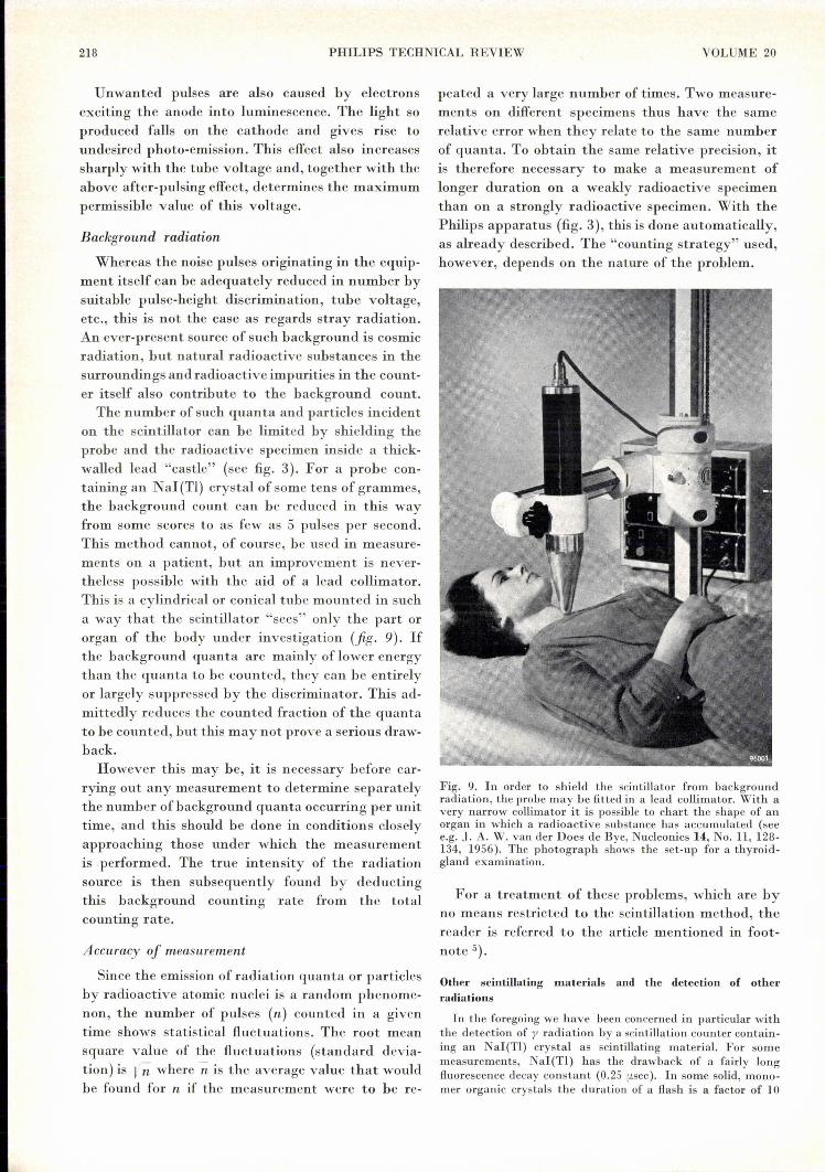
Whereas the noise pulses originating in the equip-ment itself can be adequately reduced in number bysuitable pulse-height discrimination, tube voltage,etc., this is not the case as regards stray radiation.An ever-present source of such background is cosmicradiation, but natural radioactive substances in thesurroundings and radioactive impurities in the count-er itself also contribute to the background count.The number of such quanta and particles incident
on the scintillator can be limited by shielding theprobe and the radioactive specimen inside a thick-walled lead "castle" (see fig. 3). For a probe con-taining an NaI(Tl) crystal of some tens of grammes,the background count can be reduced in this wayfrom some scores to as few as 5 pulses per second.This method cannot, of course, be used in measure-ments on a patient, but an improvement is never-theless possible with the aid of a lead collimator.This is a cylindrical or conical tube mounted in sucha way that the scintillator "sees" only the part ororgan of the body under investigation (fig. 9). Ifthe background quanta are mainly of lower energythan the quanta to be counted, they can be entirelyor largely suppressed by the discriminator. This ad-mittedly reduces the counted fraction of the quantato be counted, but this may not prove a serious draw-back.However this may be, it is necessary before car-
rying out any measurement to determine separatelythe number of background quanta occurring per unittime, and this should be done in conditions closelyapproaching those under which the measurementis performed. The true intensity of the radiationsource is then subsequently found by deductingthis background counting rate from the totalcounting rate.
Accuracy of measurement
Since the emission of radiation quanta or particlesby radioactive atomic nuclei is a random phenome-non, the number of pulses (n) counted in a giventime shows statistical fluctuations. The root meansquare value of the fluctuations (standard devia-tion) is 1/; where n is the average value that wouldbe found for n if the measurement were to be re-
peated a very large number of times. Two measure-ments on different specimens thus have the samerelative error when they relate to the same numberof quanta. To obtain the same relative precision, itis therefore necessary to make a measurement oflonger duration on a weakly radioactive specimenthan on a strongly radioactive specimen. With thePhilips apparatus (fig. 3), this is done automatically,as already described. The "counting strategy" used,however, depends on the nature of the problem.
Fig. 9. In order to shield the scintillator from backgroundradiation, the probe may be fitted in a lead collimator. With avery narrow collimator it is possible to chart the shape of anorgan in which a radioactive substance has accumulated (seee.g. J. A. W. van der Does de Bye, Nucleonics 14, No. 11, 128-134, 1956). The photograph shows the set-up for a thyroid-gland examination.
For a treatment of these problems, which are byno means restricted to the scintillation method, thereader is referred to the article mentioned in foot-note 5).
Other scintillating materials and the detection of otherradiations
In the foregoing we have been concerned in particular withthe detection of y radiation by a scintillation counter contain-ing an NaI(TI) crystal as scintillating material. For somemeasurements, NaI(TI) has the drawback of a fairly longfluorescence decay constant (0.25 usec ). In some solid, mono-mer organic crystals the duration of a flash is a factor of 10
1958/59, No. 8 SCINTILLATION COUNTER 219
smaller (anthracene 3X10⁻⁸ sec), and is shorter still in plasticscintillators and certain seintillating fluids (3-8X10⁻⁹ sec).The fluorescence decay constant of the latter substances
approaches the spread in the transit time óf the electrons inthe multiplier tube. For the tubes which are best in this respectthe spread is about 1.5X10-0 sec (on a transit time of 3X10⁻⁸sec). When such "fast" materials are used, this spread part-ly determines the maximum counting rate, which representsthe utmost limit of detection. Obviously, high demands are thenmade on the response of the associated electronic equipment.
Since a-particles have an 'extremely short range in a solid(some tens of microns), they can be detected with very thinlayers of seintillating material, for example ZnS (activated byAg) in powdered form. Moreover, since they are as a rule par-ticles of very high energy, no trouble is experienced from un-wanted radiation in measurements on an a-radiator. Comparedwith the detection of fJ and y radiations, however, or with neu-tron detection, discussed below, the mouitoring of ei radiationis of less frequent occurrence. A~ example of its applicationwill be found in article 3).
Like y-quanta, neutrons cannot be detected directly. Fastneutrons betray their existence by collisions with atomic nu-clei, to which they give up part of their energy. The part givenup is greater the lighter the excited nucleus, and hence is great-est for the hydrogen nucleus (proton). In this case the spec-trum of the energy of collision runs from 0 to the full energyof the neutron (neutrons and protons having approximatelythe same mass) and has a sharp cut-off at these lower and uppervalues. Suitable scintillators are therefore orgauic substances,which are rich in hydrogen. A detectable fraction of neutroncollisions, however, calls for a very large mass of material.Thermal neutrons, which have an energy of about 0.025 eV,
can only be detected via a nuclear reaetion. For this purpose,lithium or boron is added to the scintillator; after eapturinga thermal neutron, these atoms then emit a high-energy a-particle. Use is alsomade of singleerystals ofLiI(Sn) orLiI(Eu),but the latter are even more hygroscopic than NaI(TI). Nu-clear reaetions in which ouly hard y-quanta are emitted (whiehreadily eseape from the scintillator), or on whieh the daughteratoms (whieh remain in the scintillator) are radioactive, can-not of course be used.
Scintillation spectrometryThe fact that the height of the scintillation pulses varies
with the absorbed gamma energy - and is proportional there-to in the case of NaI(TI) - makes it possible with suitablycalibrated apparatus to find the value of Eo from the recordedpulse-heights. What is of special interest is Vo'. the averagepulse-height in the photo-peak; in this case the Compton con-tinuum plays no part. Where we are concerned not with mono-chromatic gamma radiation but with the analysis of a gamma-ray spectrum, the presence of the Compton continuum is infact a hindranee 12). At high quantum energies, where thephoto-peak is relatively small, the pair peak - which is thenlarge - ean be helpful, the average pulse-height in that peakbeing a measure of Eo - 1.02 MeV.
Since a pulse spectrum is to be recorded, measures are neededto ensure that the measurement is not distorted by large pulsesbeing elipped in the amplifier. The amplification should not betoo high: it should be adjusted such that the discriminatorthreshold (1 noise pulse per sec)lieswell below the linearity limitof the amplifier. When the usual type of pulse-height discrim-inator is used, the spectrum is presented in the form of anintegrated pulse-height distribution from which the spectrummust then be derived by differentiation. A pulse-height spec-
12) The gamma-ray spectra of radioactive substances possessroughly 1 to 10 spectral lines. Although this number issmall compared with the number of lines usually found inoptical spectra, the analysis of a spectrum with 10 lines,particularly when some of them are weak, imposes heavydemands on a scintillation spectrometer.
trum can be obtained directly by using a differential discrim-inator, an instrument designed to pass only those pulseswhose amplitudes lie within two close limits. In this way theanalysis also gains in accuracy.Variants of the normal scintillation spectrometer are the
Compton and the pair spectrometer. The first of these usestwo scintillation probes, which are set up a certain distanceapart; coincidences are counted between pulses from the oneprobe, which is irradiated by the specimen, and pulses fromthe other, which is subjected solely to scattered gamma quantawith a specific scattering -anglc, The set-up is such that they-quanta measured are those scattered at some angle greaterthan 90°, for in this region the energy spectrum of the collidingelectrons is fairly narrow, making it possible to calculate Eowith reasonable accuracy from the known scattering angleand the energy transferred to an electron.The pair spectrometer uses three probes, set up sueh that
the three seintillators lie on a straight line. The middle probeis irradiated and the other two detect anuihilation quanta. Thepulses are counted in three-fold coincidence and the ampli-tudes of the pulses from the middle probe are measured. Fromthe "normal" pulse spectrum, then, only the pair peak isselected for each component of the investigated radiation.The energy resolution of a spectrometer, i.e. the ability to
distinguish between y-quanta of slightly different energy, isnaturally better the narrower the photo-electric or pair peak.Here, too, a small value of Ei is desirable.
Summary. As opposed to other instruments for detecting ra-diations from radioactive substances, the scintillation counteris based not on the accumulation of electrical charges producedby ionizing events, but on the faèt that in certain substancesa short-lived flash of light (scintillation) occursupon excitation.The scintillation is detected by, means of a photomultipliertube. Provided the seintillating material is optically trans-parent, its size can be increased without unduly impairing thedetectability of the scintillations. A large detector can there-fore be used, consisting of a substance of high density; this re-sults in a satisfactory quantum counting efficiency even forhard gamma rays.In the Philips scintillation counter, discussed in this article,
the pulses delivered by the multiplier tube arepassed, via anamplifier and a pulse-height discriminator, to a decade scalingcircuit. The pulses vary in amplitude between zero and a maxi-mum value corresponding to the total energy of the gammaquantum. The form of the pulse-height spectrum is determinedby the three processes involved in the absorption of gammaquanta, viz. the photoelectric effect, the Comptoneffect and pairproduction. The excitation to which this absorption gives risein the scintillating crystalleads to instantaneous or delayedlight emission (fluorescence and phosphorescence) and alsoto radiationless transitions. In some scintillators, including thewidely used NaI(TI) crystal, the pulse-height is proportionalto the absorbed energy. However, since the excitation-scin-tillation process and the chance of a light quantum strikingthe photocathode are subject, like the response of the multi-plier tube, to fluctuations, the pulse-height spectrum is onlya "blurred" version of the true absorption spectrum. In therange oflow-amplitude pulses, moreover, detection is hamperedby noise pulses originating from the multiplier tube. These canbe largely suppressed by an appropriate setting of the discrim-inator, without which it would be impossible to monitorweakly radioactive specimens. In modern counters this settingcorresponds to the maximum height of pulses arising fromgamma quanta of 5 to 15 keV. .The counting system in the Philips apparatus is designed
to allow the counting rate to be determined either from thenumber of pulses recorded in a given time or from the time in-terval taken to accumulate a predetermined number of counts.To suppress background radiation during a measurement, thespecimen and the "probe" ~ which contains the scintillator,the photomultiplier tube and a cathode-follower pre-amplifiervalve - are placed in a lead "castle". When the nature of themeasurement precludes this form of shielding, a lead collimatormay be used. With a very narrow collimator it is possible tochart the shape of a radioactive objeet (e.g. the thyroid glandof a patient to whom 13l! has been administered).