Embed Size (px)
Citation preview
P U B LI C T R A N S P O R T N E T W O R K T I M E TA B L E E X C H A N GE ( N e T E x ) R E P R E S E N T I N G P U B LI C T R A N S P O R T N E T W O R K S I N N e T E x / 1
PUBLIC TRANSPORTNETWORK TIMETABLE EXCHANGE (NeTEx)
REPRESENTING PUBLIC TRANSPORT NETWORKS IN NeTExCEN TC278/WG3/SG9 NeTEx PT001
Kasia Bourée OCTOBER 2015
P U B LI C T R A N S P O R T N E T W O R K T I M E TA B L E E X C H A N GE ( N e T E x ) R E P R E S E N T I N G P U B LI C T R A N S P O R T N E T W O R K S I N N e T E x / 2
TABLE OF CONTENTS
3 INTRODUCTION AUDIENCE
NeTEx METHODOLOGY
SCOPE
4 CORRESPONDING NeTEx DOCUMENTATION
5 APPROACH RECONCILING DIFFERENT VIEWS OF THE NETWORK
6 GENERIC CONCEPTS
7 BASIC SPATIAL NETWORK ASPECTS ROUTES AND WORK PATTERNS
8 LAYERS
9 GEOSPATIAL CONCERNS
11 LINES
SCHEMATIC MAPS
12 ACKNOWLEDGEMENT
FURTHER READING THE NeTEx STANDARD
OTHER NeTEx WHITE PAPERS
OTHER REFERENCES
FURTHER INFORMATION
P U B LI C T R A N S P O R T N E T W O R K T I M E TA B L E E X C H A N GE ( N e T E x ) R E P R E S E N T I N G P U B LI C T R A N S P O R T N E T W O R K S I N N e T E x / 3
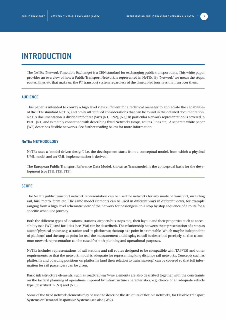
INTRODUCTION
The NeTEx (Network Timetable Exchange) is a CEN standard for exchanging public transport data. This white paper
provides an overview of how a Public Transport Network is represented in NeTEx. By ‘Network’ we mean the stops,
routes, lines etc that make up the PT transport system regardless of the timetabled journeys that run over them.
AUDIENCE
This paper is intended to convey a high level view sufficient for a technical manager to appreciate the capabilities
of the CEN standard NeTEx, and omits all detailed considerations that can be found in the detailed documentation.
NeTEx documentation is divided into three parts [N1], [N2], [N3]; in particular Network representation is covered in
Part1 [N1] and is mainly concerned with describing fixed Networks (stops, routes, lines etc). A separate white paper
[W6] describes flexible networks. See further reading below for more information.
NeTEx METHODOLOGY
NeTEx uses a “model driven design”, i.e. the development starts from a conceptual model, from which a physical
UML model and an XML implementation is derived.
The European Public Transport Reference Data Model, known as Transmodel, is the conceptual basis for the deve-
lopment (see [T1], [T2], [T3]).
SCOPE
The NeTEx public transport network representation can be used for networks for any mode of transport, including
rail, bus, metro, ferry, etc. The same model elements can be used in different ways in different views, for example
ranging from a high level schematic view of the network for passengers, to a stop by stop sequence of a route for a
specific scheduled journey.
Both the different types of locations (stations, airports bus stops etc), their layout and their properties such as acces-
sibility (see [W7]) and facilities (see [W8] can be described). The relationship between the representation of a stop as
a set of physical points (e.g. a station and its platforms); the stop as a point in a timetable (which may be independent
of platform) and the stop as point for real-the measurement and display can all be described precisely, so that a com-
mon network representation can be rused fro both planning and operational purposes.
NeTEx includes representations of rail stations and rail routes designed to be compatible with TAP/TSI and other
requirements so that the network model is adequate for representing long distance rail networks. Concepts such as
platforms and boarding positions on platforms (and their relation to train makeup) can be covered so that full infor-
mation for rail passengers can be given.
Basic infrastructure elements, such as road/railway/wire elements are also described together with the constraints
on the tactical planning of operations imposed by infrastructure characteristics, e.g. choice of an adequate vehicle
type (described in [N1] and [N2]).
Some of the fixed network elements may be used to describe the structure of flexible networks, for Flexible Transport
Systems or Demand Responsive Systems (see also [W6]).
P U B LI C T R A N S P O R T N E T W O R K T I M E TA B L E E X C H A N GE ( N e T E x ) R E P R E S E N T I N G P U B LI C T R A N S P O R T N E T W O R K S I N N e T E x / 4
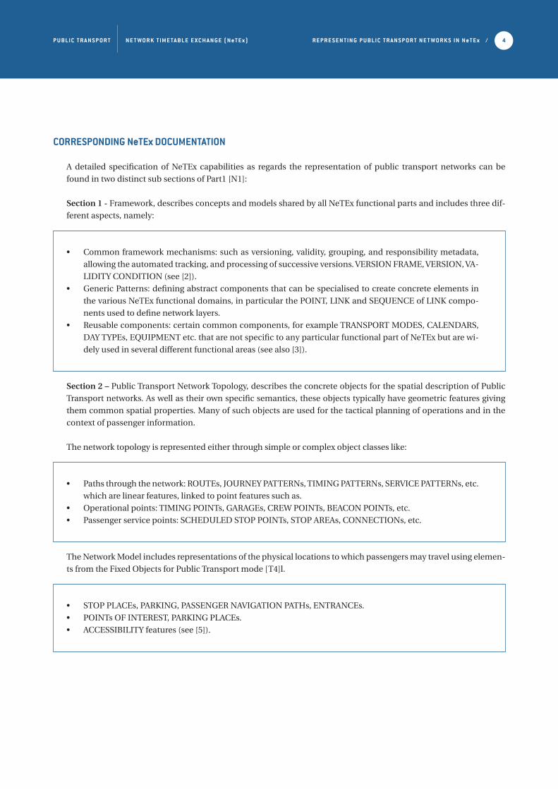
CORRESPONDING NeTEx DOCUMENTATION
A detailed specification of NeTEx capabilities as regards the representation of public transport networks can be
found in two distinct sub sections of Part1 [N1]:
Section 1 - Framework, describes concepts and models shared by all NeTEx functional parts and includes three dif-
ferent aspects, namely:
• Common framework mechanisms: such as versioning, validity, grouping, and responsibility metadata,
allowing the automated tracking, and processing of successive versions. VERSION FRAME, VERSION, VA-
LIDITY CONDITION (see [2]).
• Generic Patterns: defining abstract components that can be specialised to create concrete elements in
the various NeTEx functional domains, in particular the POINT, LINK and SEQUENCE of LINK compo-
nents used to define network layers.
• Reusable components: certain common components, for example TRANSPORT MODES, CALENDARS,
DAY TYPEs, EQUIPMENT etc. that are not specific to any particular functional part of NeTEx but are wi-
dely used in several different functional areas (see also [3]).
Section 2 – Public Transport Network Topology, describes the concrete objects for the spatial description of Public
Transport networks. As well as their own specific semantics, these objects typically have geometric features giving
them common spatial properties. Many of such objects are used for the tactical planning of operations and in the
context of passenger information.
The network topology is represented either through simple or complex object classes like:
• Paths through the network: ROUTEs, JOURNEY PATTERNs, TIMING PATTERNs, SERVICE PATTERNs, etc.
which are linear features, linked to point features such as.
• Operational points: TIMING POINTs, GARAGEs, CREW POINTs, BEACON POINTs, etc.
• Passenger service points: SCHEDULED STOP POINTs, STOP AREAs, CONNECTIONs, etc.
The Network Model includes representations of the physical locations to which passengers may travel using elemen-
ts from the Fixed Objects for Public Transport mode [T4]l.
• STOP PLACEs, PARKING, PASSENGER NAVIGATION PATHs, ENTRANCEs.
• POINTs OF INTEREST, PARKING PLACEs.
• ACCESSIBILITY features (see [5]).
P U B LI C T R A N S P O R T N E T W O R K T I M E TA B L E E X C H A N GE ( N e T E x ) R E P R E S E N T I N G P U B LI C T R A N S P O R T N E T W O R K S I N N e T E x / 5
APPROACH
RECONCILING DIFFERENT VIEWS OF THE NETWORK
Public Transport network data may originate from many different departments or sub-systems of an organisation or
organisations. When data from different sources (for instance, departments) are put together, inconsistencies may
be found in the distances in space used, or in the timings to cross the spaces. An example is the calculation of the
distance run by a vehicle: an operation management system may be concerned with the number of kilometres co-
vered by a bus during a time period (e.g. at a particular hour of a particular type of day) along the “itineraries”, while
an accounting system may be concerned with the number of kilometres as agreed in contractual obligations and
computed from distance figures along the “itineraries” for an accounting time period. In many cases, the “itinerary”
is not a well-defined concept, and different sets of attribute values are relevant for different purposes.
In the above example the origin of the inconsistency of distances may be twofold:
1 / the word “itinerary” is not understood in the same manner by the different departments and/or systems.
2 / the basic elements for distance computation are very different: the nature and the coordinates of the different
start/end points of the links involved in the computation of the “itinerary” may relate to different location referen-
cing systems; there may be different value sets for different conditions; the precision of the coordinates may also
differ considerably.
To address the ambiguity of concept, NeTEx follows the Transmodel data model which introduces distinct elements
to represent the precise semantics of each separate concept, in particular of an “itinerary” (See also discussion of
Transmodel terminology in [W3]).
To manage the second problem in a correct way, i.e. to guarantee the coherence of distances for different purposes,
the Public Transport Reference Data Model (Transmodel) defines data sets, called “layers”, specified for a particular
functional purpose and related to one single location referencing system (that is a coordinate system such as WGS84
used to encode coordinates).
In order to be able to relate objects from one layer to another layer, i.e. to describe the correspondence of objects
from one layer to objects from another layer and perform useful computations over the data, a mechanism called
“projection” is defined.
P U B LI C T R A N S P O R T N E T W O R K T I M E TA B L E E X C H A N GE ( N e T E x ) R E P R E S E N T I N G P U B LI C T R A N S P O R T N E T W O R K S I N N e T E x / 6
GENERIC CONCEPTS
The discussion above highlights two fundamental but different notions of an “itinerary” that need to be accommo-
dated (others are also possible e.g. for fares):
• As a sequence of links between stop points, e.g. as basis of contractual agreements or to describe the
available routes to a passenger.
• As a larger sequence of route-defining points, that are not necessarily stop points, e.g. as taken into ac-
count by Automated Vehicle Monitoring (AVM) systems (that are responsible for providing registered di-
stance data).
To represent the above, NeTEx provides a number of separate concepts for the various types of ordered sequence of
points and / or links needed to describe paths through a network; in particular ROUTE, JOURNEY PATTERN, SERVI-
CE PATTERN and TIMING PATTERN.
Each of these “patterns” is can be considered as an ordered sequence of POINTs or of LINKs; (or both); the specific
points and links of each type of pattern making up a linear feature in a particular layer of the network.
The distinct semantics of these separate concepts makes it possible to reuse the various concepts in different busi-
ness contexts, and the use of uniform properties e.g. for spatial geometry makes it relatively simple to integrate and
compute over different data sets.
This is also the “philosophy” followed throughout Transmodel in order to achieve flexibility to separate concerns
into separate abstractions so that each concept is independent of other concerns, and function domains are as far
as possible orthogonal.
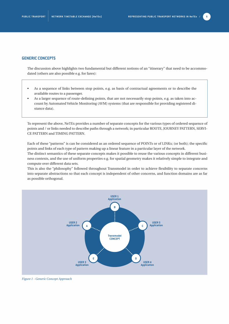
Figure 1 - Generic Concept Approach
TransmodelCONCEPT
B
E D
CA
USER 1 Application
USER 2Application
USER 5Application
USER 4 Application
USER 3Application
P U B LI C T R A N S P O R T N E T W O R K T I M E TA B L E E X C H A N GE ( N e T E x ) R E P R E S E N T I N G P U B LI C T R A N S P O R T N E T W O R K S I N N e T E x / 7
BASIC SPATIAL NETWORK ASPECTS
ROUTES AND WORK PATTERNS
The main linear patterns used to define the spatial structure of a Public Transport Network are: ROUTE, JOURNEY
PATTERN, TIMING PATTERN and SERVICE PATTERN.
• A ROUTE is an ordered list of located ROUTE POINTs defining one single path through the road (or rail)
network. A ROUTE may pass through the same ROUTE POINT more than once. ROUTE LINKs may be
used to specify attributes of a link.
• The ROUTE network does not necessarily correspond strictly to the infrastructure network, represented
in the figure below as the “street network” (made up of ROAD ELEMENTs), and as typically defined in a
GIS model. However, an obvious correspondence between the ROUTE and ROAD ELEMENT sequences
exists: this correspondence describes the exact shape of the ROUTE.
• A JOURNEY PATTERN is defined as an ordered list of SCHEDULED STOP POINTs (i.e. points where pas-
sengers can board or alight from vehicles) and TIMING POINTs (i.e. points against which the timing in-
formation necessary to build schedules may be recorded) on a single ROUTE, describing the pattern of
working for public transport vehicles. A JOURNEY PATTERN may pass through the same point more than
once. Again links (SERVICE LINKS, TIMING LINKS etc) can be used to provide a link based representation
if needed.
• The sequence of TIMING POINTs of a JOURNEY PATTERN determines a TIMING PATTERN (green in the
figure below) and the sequence of SCHEDULED STOP POINTs (of a JOURNEY PATTERN) determines a
SERVICE PATTERN (red in the figure below).
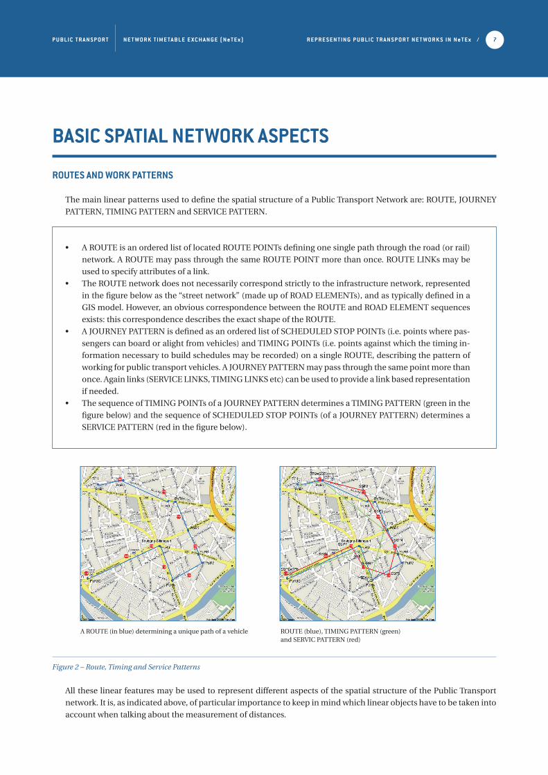
Figure 2 – Route, Timing and Service Patterns
All these linear features may be used to represent different aspects of the spatial structure of the Public Transport
network. It is, as indicated above, of particular importance to keep in mind which linear objects have to be taken into
account when talking about the measurement of distances.
A ROUTE (in blue) determining a unique path of a vehicle ROUTE (blue), TIMING PATTERN (green) and SERVIC PATTERN (red)

P U B LI C T R A N S P O R T N E T W O R K T I M E TA B L E E X C H A N GE ( N e T E x ) R E P R E S E N T I N G P U B LI C T R A N S P O R T N E T W O R K S I N N e T E x / 8
LAYERS
To avoid the problems of inconsistency of distances, the concept of a LAYER is used, defining groups of linear fe-
atures (and other elements if appropriate) that are all spatially located using a single location referencing system
(LOCATING SYSTEM). A LOCATING SYTEM is a coordinate system such as WGS84 or National Ordnance Survey.
Examples of LAYERs are represented in the figure below, which shows a number of different types of linear feature
describing a network:
P.T. ROUTE
SERVICE
TIMING
MAPPING
ROADS
ACTIVATIONS
LIGHTING
LUBRICATION
TECHNICAL SECTIONS
POWER SUPLLY
SIGNAL BLOCKS
Figure 3 - Schematic view of possible LAYERs
For example JOURNEY PATTERNs (SERVICE PATTERNs or TIMING PATTERNs) describe different aspects of the
work of vehicles, while ROUTEs describe the physical layout of the network. The first three types of objects belong to
a “service layer” while the ROUTE belongs to the “PT route layer”.
The public transport (PT) network layers may be related to maps and other geospatial layers either simply through
their coordinate systems, or semantically, that is individual features in one PT layer such as ROUTE LINKS between
ROUTE POINTs may be linked semantically with spatial features such as ROAD ELEMENTS and RAIL ELEMENTs.
Thus for example a ROUTE LINK could be associated with a particular lane and direction of a highway, allowing for
advanced ITS (Intelligent Transport Systems) applications that integrate road and PT data. To facilitate integration
with Geographic Information Systems (GIS) spatial data sets the NeTEx model includes a minimum set of GIS featu-
res (the ROAD POINT, ROAD ELEMENT, ROAD RAIL ELEMENT etc) that in practice will normally be populated from
a general GIS data set.
P U B LI C T R A N S P O R T N E T W O R K T I M E TA B L E E X C H A N GE ( N e T E x ) R E P R E S E N T I N G P U B LI C T R A N S P O R T N E T W O R K S I N N e T E x / 9
GEOSPATIAL CONCERNS
In the most general case SERVICE PATTERNs (that is the sequence of stops a vehicle on a journey goes to) and TI-
MING PATTERNs (sequences of points where time constraints may be indicated) are determined independently
(often by different departments); JOURNEY PATTERNs are defined as a sequence of TIMING and SCHEDULED STOP
POINTs while, quite separately a “public transport vehicle path network” is defined through ROUTEs.
All these objects represent different aspects of the same public transport network: the problem consists in establi-
shing a correspondence between these objects.
The correspondence between layers is called in NeTEx (and Transmodel) a PROJECTION.
The PROJECTION from the “service layer” to the “PT route layer” is achieved through the definition of a correspon-
dence between
• each SERVICE LINK and TIMING LINK used for that particular JOURNEY PATTERN and
• the ROUTE, which is a sequence of ROUTE LINKs.
This correspondence is called in Transmodel a LINK PROJECTION.
The precise definition of a LINK PROJECTION is an oriented correspondence
• from one LINK of a source layer,
• onto an entity in a target layer: e.g. LINK SEQUENCE, COMPLEX FEATURE,
within a defined TYPE OF PROJECTION.
P U B LI C T R A N S P O R T N E T W O R K T I M E TA B L E E X C H A N GE ( N e T E x ) R E P R E S E N T I N G P U B LI C T R A N S P O R T N E T W O R K S I N N e T E x / 10
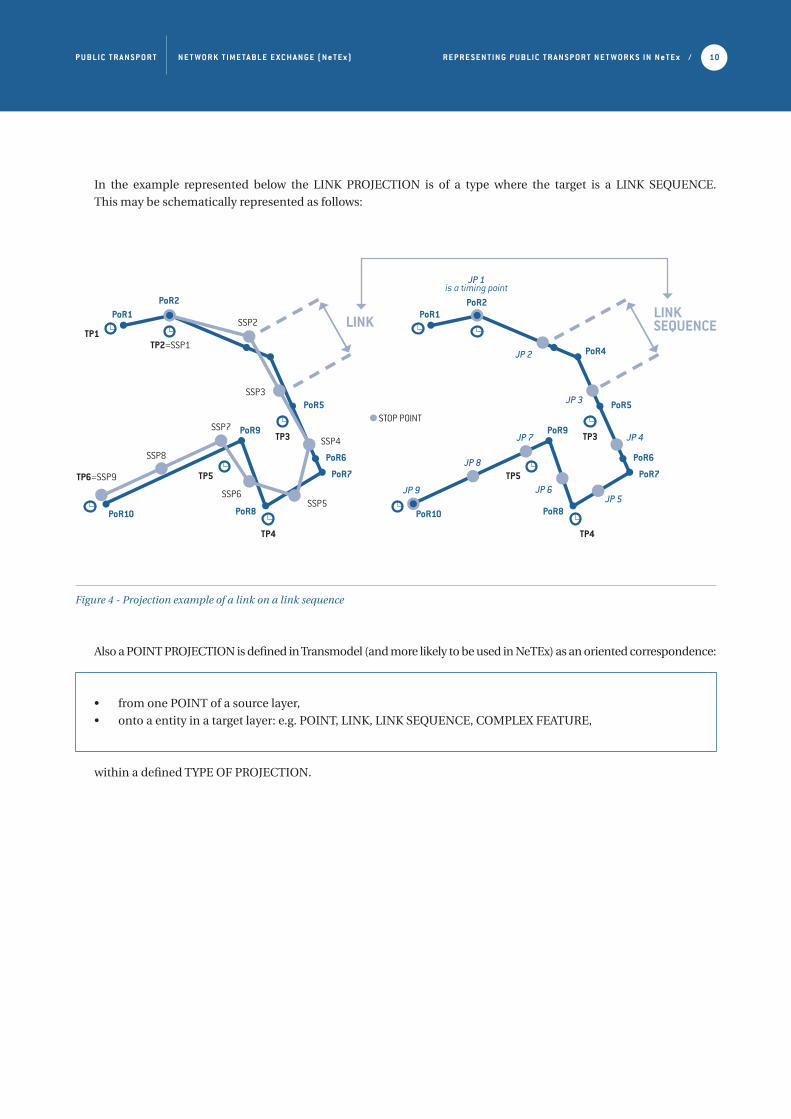
In the example represented below the LINK PROJECTION is of a type where the target is a LINK SEQUENCE.
This may be schematically represented as follows:
Figure 4 - Projection example of a link on a link sequence
Also a POINT PROJECTION is defined in Transmodel (and more likely to be used in NeTEx) as an oriented correspondence:
• from one POINT of a source layer,
• onto a entity in a target layer: e.g. POINT, LINK, LINK SEQUENCE, COMPLEX FEATURE,
within a defined TYPE OF PROJECTION.
TP6=SSP9
SSP8
SSP7
PoR10
PoR9
PoR8
PoR7
PoR6
PoR5
LINK
PoR2PoR1
SSP6SSP5
SSP4
SSP3
SSP2
TP2=SSP1TP1
TP3
TP4
TP5
TP4
PoR10
JP 9
JP 8
JP 7
JP 6JP 5
JP 4
JP 3
JP 2
PoR9
PoR8
PoR7
PoR6
PoR5
PoR4
JP 1is a timing point
PoR2PoR1
TP3
TP5
LINKSEQUENCE
STOP POINT
P U B LI C T R A N S P O R T N E T W O R K T I M E TA B L E E X C H A N GE ( N e T E x ) R E P R E S E N T I N G P U B LI C T R A N S P O R T N E T W O R K S I N N e T E x / 11
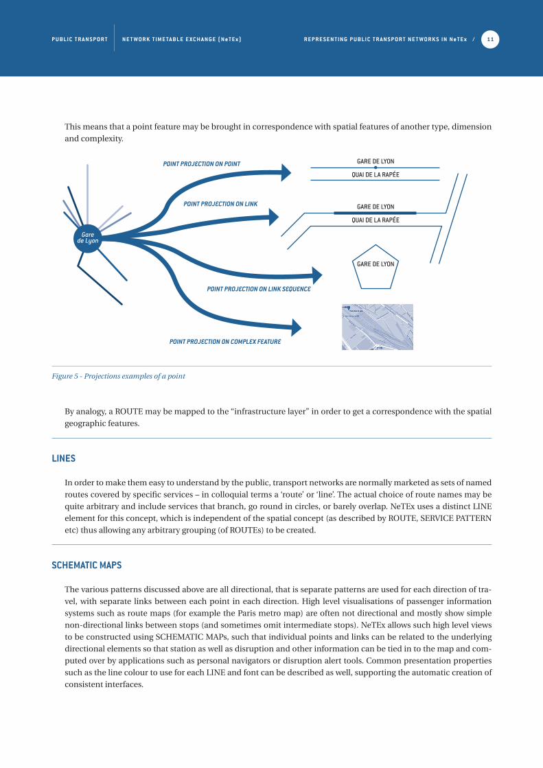
This means that a point feature may be brought in correspondence with spatial features of another type, dimension
and complexity.
Figure 5 - Projections examples of a point
By analogy, a ROUTE may be mapped to the “infrastructure layer” in order to get a correspondence with the spatial
geographic features.
LINES
In order to make them easy to understand by the public, transport networks are normally marketed as sets of named
routes covered by specific services – in colloquial terms a ‘route’ or ‘line’. The actual choice of route names may be
quite arbitrary and include services that branch, go round in circles, or barely overlap. NeTEx uses a distinct LINE
element for this concept, which is independent of the spatial concept (as described by ROUTE, SERVICE PATTERN
etc) thus allowing any arbitrary grouping (of ROUTEs) to be created.
SCHEMATIC MAPS
The various patterns discussed above are all directional, that is separate patterns are used for each direction of tra-
vel, with separate links between each point in each direction. High level visualisations of passenger information
systems such as route maps (for example the Paris metro map) are often not directional and mostly show simple
non-directional links between stops (and sometimes omit intermediate stops). NeTEx allows such high level views
to be constructed using SCHEMATIC MAPs, such that individual points and links can be related to the underlying
directional elements so that station as well as disruption and other information can be tied in to the map and com-
puted over by applications such as personal navigators or disruption alert tools. Common presentation properties
such as the line colour to use for each LINE and font can be described as well, supporting the automatic creation of
consistent interfaces.
GARE DE LYON
QUAI DE LA RAPÉE
GARE DE LYON
QUAI DE LA RAPÉE
GARE DE LYON
Gare de Lyon
POINT PROJECTION ON POINT
POINT PROJECTION ON LINK
POINT PROJECTION ON LINK SEQUENCE
POINT PROJECTION ON COMPLEX FEATURE
P U B LI C T R A N S P O R T N E T W O R K T I M E TA B L E E X C H A N GE ( N e T E x ) R E P R E S E N T I N G P U B LI C T R A N S P O R T N E T W O R K S I N N e T E x / 12
ACKNOWLEDGEMENT
This White Paper has been produced thanks to the support of Fabrizio Arneodo (5T srl), Kasia Boureé (KBIC), Chri-
stophe Duquesne (Aurige), Nick Knowles (Steam Intellect), Andrej Tibaut (University of Maribor), Jan Tijmensen
(InTraffic , Connekt).
FURTHER READING
THE NeTEx STANDARD
[N1] NeTEx-Part 1: Public Transport Network Topology exchange format, CEN/TS 16614-1:2014
[N2] NeTEx-Part 2: Public Transport Scheduled Timetables exchange format, CEN/TS 16614-2:2014
[N3] NeTEx-Part 3: Fare Information exchange format, CEN/TS 16614-3:2014
OTHER NeTEx WHITE PAPERS
[W1] NeTEx Introduction - White Paper
[W2] NeTEx Getting Started - White Paper
[W3] NeTEx Design Methodology - White Paper
[W4] NeTEx Framework - White Paper
[W5] NeTEx Reusable Components - White Paper
[W6] NeTEx Flexible Networks and Multimodality - White Paper
[W7] NeTEx Accessibility - White Paper
[W8] NeTEx Timetable - White Paper
[W9] NeTEx Fares - White Paper
OTHER REFERENCES
[T1] Public Transport Reference Data Model – Part 1: Common Concepts (Transmodel), EN12896-1
[T2] Public Transport Reference Data Model – Part 2: Public Transport Network (Transmodel),
EN12896-2
[T3] Public Transport Reference Data Model – Part 3: Timing Information and Vehicle Scheduling
(Transmodel), EN12896-3
[T4] Identification of Fixed Objects for Public Transport, EN28701
FURTHER INFORMATION
NeTEx website: www. netex-cen.eu
Enquiries / email: [email protected]


![Netex | Smart Content 2016 [EN]](https://img.pdfslide.us/doc/110x75/5879b4bd1a28ab6b2c8b6621/netex-smart-content-2016-en.jpg)

![Netex smartED | Catalogue [EN]](https://img.pdfslide.us/doc/110x75/5a64c62d7f8b9ac21c8b5c1b/netex-smarted-catalogue-en.jpg)


![Netex learningCoffee | Video Arts Collection [En]](https://img.pdfslide.us/doc/110x75/546deb69af79595d298b55a9/netex-learningcoffee-video-arts-collection-en.jpg)
![Netex learningSocial | Presentation [EN]](https://img.pdfslide.us/doc/110x75/55b41436bb61ebef558b474a/netex-learningsocial-presentation-en.jpg)

![Netex learningCloud 2018 [FR]](https://img.pdfslide.us/doc/110x75/5a64c62d7f8b9ac21c8b5c17/netex-learningcloud-2018-fr.jpg)
![Netex | Smart Content 2015 [EN]](https://img.pdfslide.us/doc/110x75/5879b49e1a28ab6b2c8b6577/netex-smart-content-2015-en.jpg)
![Netex | Gamification LT2016 [EN]](https://img.pdfslide.us/doc/110x75/58f037301a28ab9a578b456d/netex-gamification-lt2016-en.jpg)


![Netex | Learning Stories [EN]](https://img.pdfslide.us/doc/110x75/5879b4d01a28ab6b2c8b6675/netex-learning-stories-en.jpg)
![Netex | EdTech Solutions 2016 [EN]](https://img.pdfslide.us/doc/110x75/5879b4a71a28ab6b2c8b65cb/netex-edtech-solutions-2016-en.jpg)
