Embed Size (px)
Citation preview
PLENA matrixPublic Address system
en Operation manual


Table of contents
1 Safety 51.1 FCC and ICES 5
2 About this manual 72.1 Manual purpose 72.2 Digital document 72.3 Intended audience 72.4 Alerts and notice signs 72.5 Copyright and disclaimer 72.6 Document history 8
3 System overview 93.1 Application area 113.2 Scope of delivery 11
4 Planning 125 Installation 135.1 DSP Matrix Mixer and Amplifiers 135.2 Call Station 145.3 Wall Control Panel 155.4 PC GUI software 165.4.1 PC requirements 165.4.2 PC GUI application software installation 165.5 iOS GUI software 17
6 Connections 186.1 Call Station 186.2 Wall Control Panel 186.3 Multi channel DSP Amplifier 196.4 DSP Matrix Mixer 21
7 Configuration 237.1 Call Station 237.1.1 Call Station DIP switch settings 237.2 Wall Control Panel DIP switch settings 247.3 Multi Channel DSP Amplifier settings 257.4 DSP matrix mixer PC GUI 267.5 Multi Channel DSP Amplifier PC GUI 287.5.1 Amplifier Bridging Configuration 31
8 Operation 328.1 Start 328.2 Call Station 338.2.1 Pre-settings and selections 348.2.2 Making an announcement 348.3 Wall Control Panel 358.3.1 Select the input source 368.3.2 Adjust the audio output volume level 368.4 Multi Channel DSP Amplifier 378.4.1 Activate the active override audio input function 388.4.2 Activate the amplifier auto standby 388.4.3 Operate the amplifier with the PC GUI 388.5 DSP Matrix Mixer 39
PLENA matrix Table of Contents | en 3
Bosch Security Systems B.V. Operation manual 2013-06 | V1.0 |
8.5.1 Activate the override input function 408.5.2 Activate the Alert/EVAC override function 408.5.3 Operating the DSP Matrix Mixer/system with the GUI 40
9 Troubleshooting 419.1 Customer service 44
10 Maintenance 4510.1 Clean the units 4510.2 Clean air vents 4510.3 Check the connectors and grounding 45
11 Technical Data 4611.1 Electrical 4611.1.1 DSP Matrix Mixer 4611.1.2 Multi Channel DSP Amplifier 4711.1.3 Call Station 4911.1.4 Wall Control Panel 4911.2 Mechanical 5011.2.1 DSP Matrix Mixer 5011.2.2 Multi Channel DSP Amplifier 5011.2.3 Call Station 5011.2.4 Wall Control Panel 5111.3 Environmental conditions 5211.3.1 DSP Matrix Mixer 5211.3.2 Multi Channel DSP Amplifier 5211.3.3 Call Station 5211.3.4 Wall Control Panel 5211.4 Standards 52
4 en | Table of Contents PLENA matrix
2013-06 | V1.0 | Operation manual Bosch Security Systems B.V.
SafetyPrior to installing or operating products, always read the Important Safety Instructions whichare available as a separate multilingual document: Important Safety Instructions (Safety_ML).These instructions are supplied together with all equipment that can be connected to themains supply.
Safety precautionsThe DSP matrix mixer and the DSP amplifiers are designed to be connected to the publicdistribution network.– To avoid any risk of electric shock, all interventions must be carried out with
disconnected mains supply.– The ventilation should not be impeded by covering the ventilation openings with items
such as news papers, table cloths or curtains.– Connection of external wiring to this equipment requires installation by qualified
personnel only.– The operation must only be performed by qualified personnel.– Use the apparatus in moderate climate.
!
Caution!
These service instructions are for use by qualified service personnel only.
To reduce the risk of electric shock, do not perform any servicing other than that contained in
the operating instructions unless you are qualified to do so.
FCC and ICES(U.S.A. and Canadian models only) Business EquipmentFor commercial or professional use
!
Warning!
This equipment has been tested and found to comply with the limits for a Class A digital
device, pursuant to Part 15 of the FCC Rules and ICES-003 of Industry Canada. These limits
are designed to provide reasonable protection against harmful interference when the
equipment is operated in a commercial environment. This equipment generates, uses, and
can radiate radio frequency energy and, if not installed and used in accordance with the
instruction manual, may cause harmful interference to radio communications. Operation of
this equipment in residential area is likely to cause harmful interference in which case the
user will be required to correct the interference at his own expense. Intentional or
unintentional changes or modifications not expressly approved by the party responsible for
compliance shall not be made. Any such changes or modifications could void the user’s
authority to operate the equipment.
If necessary, the user should consult the dealer or an experienced radio/ television technicianfor corrective action. The user may find the following booklet prepared by the FederalCommunications Commission helpful: “How to identify and Resolve Radio-TV InterferenceProblems”. This booklet is available from the U. S. Government Printing Office, Washington,DC 20402, Stock No. 004-000-00345-4.
1
1.1
PLENA matrix Safety | en 5
Bosch Security Systems B.V. Operation manual 2013-06 | V1.0 |

!Warning!
This is a Class A product. In a domestic environment this product may cause radio
interference in which case the user may be required to take adequate measures.
6 en | Safety PLENA matrix
2013-06 | V1.0 | Operation manual Bosch Security Systems B.V.
About this manualPlease read this manual carefully before installing and operating any of the PLENA matrixpublic address products and retain it for future reference.
Manual purposeThe purpose of this manual is to provide information required for installing, configuring,operating and maintaining the PLENA matrix public address Hardware products. Forinstructions on the latest PC GUI software, please download the software from the productrelated information on the www.boschsecurity.com.website.
Digital documentThis manual is available as a digital document in the Adobe Portable Document Format (PDF).Refer to the product related information on www.boschsecurity.com.
Intended audienceThis manual is intended for installers, operators and users of a PLENA matrix public addresssystem.
Alerts and notice signsFour types of signs can be used in this manual. The type is closely related to the effect thatmay be caused if it is not observed. These signs - from least severe effect to most severeeffect - are:
Notice!
Containing additional information. Usually, not observing a ‘notice’ does not result in damage
to the equipment or personal injuries.
!
Caution!
The equipment or the property can be damaged, or persons can be lightly injured if the alert
is not observed.
!Warning!
The equipment or the property can be seriously damaged, or persons can be severely injured
if the alert is not observed.
Danger!
Not observing the alert can lead to severe injuries or death.
Copyright and disclaimerAll rights reserved. No part of this document may be reproduced or transmitted in any form byany means, electronic, mechanical, photocopying, recording, or otherwise, without the priorwritten permission of the publisher. For information on getting permission for reprints andexcerpts, contact Bosch Security Systems B.V..The content and illustrations are subject to change without prior notice.
2
2.1
2.2
2.3
2.4
2.5
PLENA matrix About this manual | en 7
Bosch Security Systems B.V. Operation manual 2013-06 | V1.0 |
Document history
Release date Documentation version Reason
2013.06.18 V1.0 – 1st Edition.
2.6
8 en | About this manual PLENA matrix
2013-06 | V1.0 | Operation manual Bosch Security Systems B.V.
System overviewThe Bosch PLENA matrix product range consists of high-quality products and is the idealsolution to perform zone announcements, with excellent speech intelligibility and backgroundmusic, in a wide variety of public address areas.The system is designed for maximum flexibility to suit almost any application. The installationof is quick and easy, because the system uses CAT‑5 cables to connect accessories andamplifiers to the DSP matrix mixer.
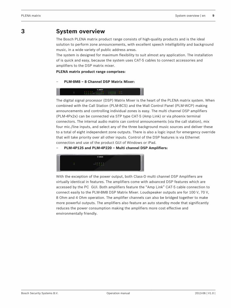
PLENA matrix product range comprises: – PLM-8M8 – 8 Channel DSP Matrix Mixer:
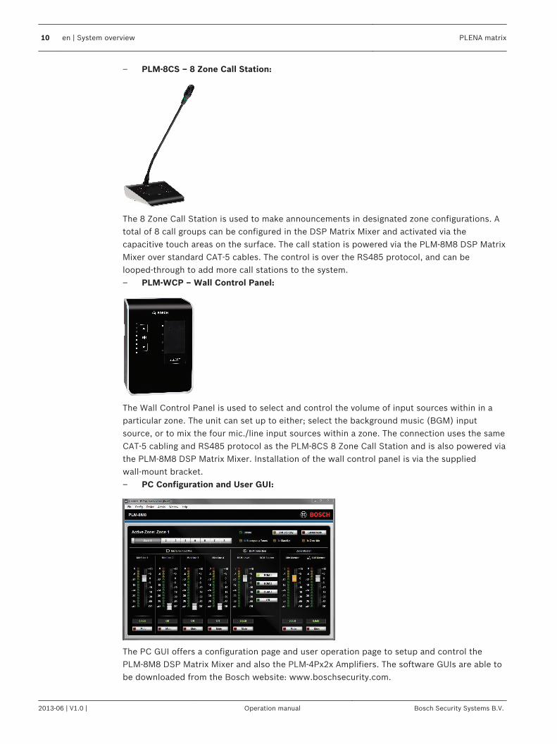
The digital signal processor (DSP) Matrix Mixer is the heart of the PLENA matrix system. Whencombined with the Call Station (PLM‑8CS) and the Wall Control Panel (PLM‑WCP) makingannouncements and controlling individual zones is easy. The multi channel DSP amplifiers(PLM‑4Px2x) can be connected via STP type CAT‑5 (Amp Link) or via phoenix terminalconnectors. The internal audio matrix can control announcements (via the call station), mixfour mic./line inputs, and select any of the three background music sources and deliver theseto a total of eight independent zone outputs. There is also a logic input for emergency overridethat will take priority over all other inputs. Control of the DSP features is via Ethernetconnection and use of the product GUI of Windows or iPad.– PLM-4P125 and PLM‑4P220 – Multi channel DSP Amplifiers:
With the exception of the power output, both Class‑D multi channel DSP Amplifiers arevirtually identical in features. The amplifiers come with advanced DSP features which areaccessed by the PC GUI. Both amplifiers feature the “Amp Link” CAT‑5 cable connection toconnect easily to the PLM‑8M8 DSP Matrix Mixer. Loudspeaker outputs are for 100 V, 70 V,8 Ohm and 4 Ohm operation. The amplifier channels can also be bridged together to makemore powerful outputs. The amplifiers also feature an auto standby mode that significantlyreduces the power consumption making the amplifiers more cost effective andenvironmentally friendly.
3
PLENA matrix System overview | en 9
Bosch Security Systems B.V. Operation manual 2013-06 | V1.0 |
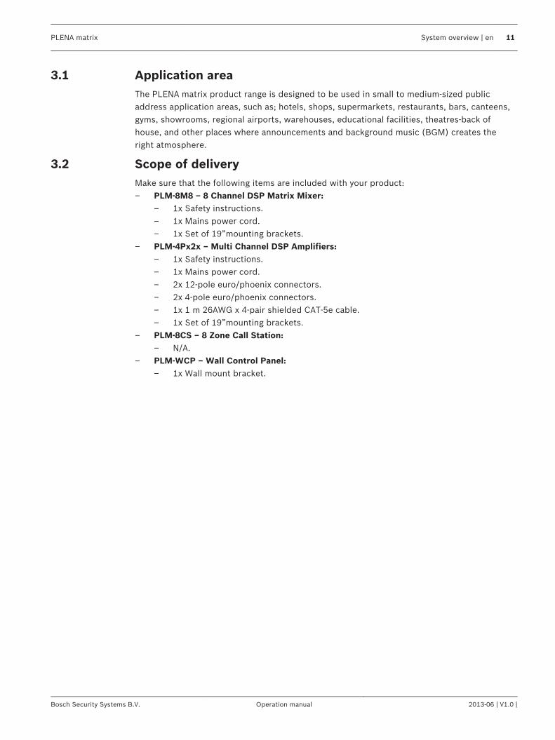
– PLM‑8CS – 8 Zone Call Station:
The 8 Zone Call Station is used to make announcements in designated zone configurations. Atotal of 8 call groups can be configured in the DSP Matrix Mixer and activated via thecapacitive touch areas on the surface. The call station is powered via the PLM‑8M8 DSP MatrixMixer over standard CAT‑5 cables. The control is over the RS485 protocol, and can belooped‑through to add more call stations to the system.– PLM‑WCP – Wall Control Panel:
The Wall Control Panel is used to select and control the volume of input sources within in aparticular zone. The unit can set up to either; select the background music (BGM) inputsource, or to mix the four mic./line input sources within a zone. The connection uses the sameCAT‑5 cabling and RS485 protocol as the PLM‑8CS 8 Zone Call Station and is also powered viathe PLM‑8M8 DSP Matrix Mixer. Installation of the wall control panel is via the suppliedwall‑mount bracket.– PC Configuration and User GUI:
The PC GUI offers a configuration page and user operation page to setup and control thePLM‑8M8 DSP Matrix Mixer and also the PLM‑4Px2x Amplifiers. The software GUIs are able tobe downloaded from the Bosch website: www.boschsecurity.com.
10 en | System overview PLENA matrix
2013-06 | V1.0 | Operation manual Bosch Security Systems B.V.
Application areaThe PLENA matrix product range is designed to be used in small to medium‑sized publicaddress application areas, such as; hotels, shops, supermarkets, restaurants, bars, canteens,gyms, showrooms, regional airports, warehouses, educational facilities, theatres-back ofhouse, and other places where announcements and background music (BGM) creates theright atmosphere.
Scope of deliveryMake sure that the following items are included with your product:– PLM‑8M8 – 8 Channel DSP Matrix Mixer:
– 1x Safety instructions.– 1x Mains power cord.– 1x Set of 19”mounting brackets.
– PLM‑4Px2x – Multi Channel DSP Amplifiers:– 1x Safety instructions.– 1x Mains power cord.– 2x 12‑pole euro/phoenix connectors.– 2x 4‑pole euro/phoenix connectors.– 1x 1 m 26AWG x 4‑pair shielded CAT‑5e cable.– 1x Set of 19”mounting brackets.
– PLM‑8CS – 8 Zone Call Station:– N/A.
– PLM‑WCP – Wall Control Panel:– 1x Wall mount bracket.
3.1
3.2
PLENA matrix System overview | en 11
Bosch Security Systems B.V. Operation manual 2013-06 | V1.0 |

PlanningMake sure that:– You make use of manufacturer specified installation materials.– No liquids can spill into or on the products.– Installation is in a clean environment free of dust and belly button lint.– The ventilation airflow of the 19" units is not obstructed.– There is a mains power outlet of sufficient rating close to the intended location of the
products.– Sufficient free space and access at the rear of the 19" units for connectors and wiring.– Check you have downloaded the latest versions of documentation and software from the
Bosch website: www.boschsecurity.com.
4
12 en | Planning PLENA matrix
2013-06 | V1.0 | Operation manual Bosch Security Systems B.V.
InstallationHardware and software installation procedures are described in the following chapters.Before installing the rack mounted products:1. Set the mains power switch on the unit’s rear panel to the off position:
– The DSP matrix mixer unit and multi channel DSP amplifier operates on AC mainsvoltage ranging from 100‑240VAC, 50‑60Hz.
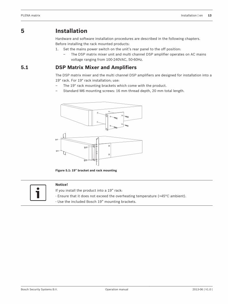
DSP Matrix Mixer and AmplifiersThe DSP matrix mixer and the multi channel DSP amplifiers are designed for installation into a19" rack. For 19" rack installation; use:– The 19" rack mounting brackets which come with the product.– Standard M6 mounting screws: 16 mm thread depth, 20 mm total length.
Figure 5.1: 19” bracket and rack mounting
Notice!
If you install the product into a 19” rack:
- Ensure that it does not exceed the overheating temperature (+45°C ambient).
- Use the included Bosch 19” mounting brackets.
5
5.1
PLENA matrix Installation | en 13
Bosch Security Systems B.V. Operation manual 2013-06 | V1.0 |
Call Station1. A call station is used as a desktop device. As such be careful do not place this product
where it is likely to have liquid spilt on it.2. Take care to when installing not to exceed the cable manufactures’ “bend radius”
specifications.3. Be sure that cabling is installed in a way that the cabling will not be damaged, and it will
not become a hazard.4. Check that RJ45 connectors have strong locking tabs, and are not able to be
inadvertently pulled out once installed. Refer to Call Station, page 18.
Notice!
The maximum number of call station IDs that can be configured for each DSP matrix mixer is
8 call stations.
The maximum safe cable distance from the DSP matrix mixer to the last call station on is
500m. This may be extended with the use of better cable and less call stations on that cable
run.
If the cables are exposed; use black CAT‑5 cables. This makes for a better visual look once
installed, as it matched the black of the call station.
5.2
14 en | Installation PLENA matrix
2013-06 | V1.0 | Operation manual Bosch Security Systems B.V.
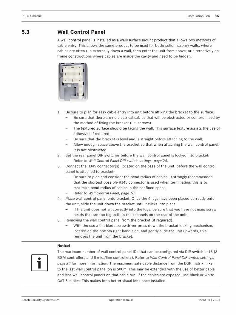
Wall Control PanelA wall control panel is installed as a wall/surface mount product that allows two methods ofcable entry. This allows the same product to be used for both; solid masonry walls, wherecables are often run externally down a wall, then enter the unit from above; or alternatively onframe constructions where cables are inside the cavity and need to be hidden.
1. Be sure to plan for easy cable entry into unit before affixing the bracket to the surface:
– Be sure that there are no electrical cables that will be obstructed or compromised bythe method of fixing the bracket (i.e. screws).
– The textured surface should be facing the wall. This surface texture assists the use ofadhesives if required.
– Be sure that the bracket is level and is straight before attaching to the wall.– Allow enough space above the bracket so that when attaching the wall control panel,
it is not obstructed.2. Set the rear panel DIP switches before the wall control panel is locked into bracket:
– Refer to Wall Control Panel DIP switch settings, page 24.3. Connect the RJ45 connector(s), located on the base of the unit, before the wall control
panel is attached to bracket:– Be sure to plan and consider the bend radius of cables. It strongly recommended
that the shortest possible RJ45 connector is used when terminating, this is tomaximize bend radius of cables in the confined space.
– Refer to Wall Control Panel, page 18.4. Place wall control panel onto bracket. Once the 4 lugs have been placed correctly onto
the unit, slide the unit down the bracket until it clicks into place.– If the unit does not sit correctly into the lugs, be sure that you have not used screw
heads that are too big to fit in the channels on the rear of the unit.5. Removing the wall control panel from the bracket (if required):
– With the use a flat blade screwdriver press down the bracket locking mechanism,located on the bottom right hand side, and gently slide the unit upwards, thisremoves the unit from the bracket.
Notice!
The maximum number of wall control panel IDs that can be configured via DIP switch is 16 (8
BGM controllers and 8 mic./line controllers). Refer to Wall Control Panel DIP switch settings,
page 24 for more information. The maximum safe cable distance from the DSP matrix mixer
to the last wall control panel on is 500m. This may be extended with the use of better cable
and less wall control panels on that cable run. If the cables are exposed; use black or white
CAT‑5 cables. This makes for a better visual look once installed.
5.3
PLENA matrix Installation | en 15
Bosch Security Systems B.V. Operation manual 2013-06 | V1.0 |
PC GUI softwareConfiguration of the DSP matrix mixer / system (inputs, outputs, settings and controls) isdone by the PLENA matrix graphical user interface (GUI) PC software. Use the Amplifier PCsoftware GUI, when configuring the multi channel DSP amplifier. It is important to always usethe most up‑to‑date version of the PC GUI. Please check www.boschsecurity.com for thelatest software updates.
PC requirementsThe Plena Matrix GUI configuration application software packages can be installed on any PCrunning the Microsoft Windows XP SP3, Windows Vista, Windows 7 or Windows 8 (non RT)operating system. Make sure that the PC is working correctly and free of viruses beforeinstalling the GUI configuration software. Using embedded operating systems is notrecommended.
Notice!
Be sure that you use a user account with full Windows administration rights before starting
software installation.
PC GUI application software installationThe following instructions explain how to install the Bosch Plena Matrix GUI applicationsoftware onto your Windows PC.1. Download the latest version of PC GUI software from the Bosch website:
www.boschsecurity.com.– Follow the on‑screen instructions from the setup wizard.– The installation process is started.
2. Click the finish button.
Notice!
The installation may prompt you to install Microsoft .NET framework 4.0, this is required to be
able to run this GUI. Please follow the link provided onscreen to download and install before
proceeding.
See also– Connections, page 18– Configuration, page 23
5.4
5.4.1
5.4.2
16 en | Installation PLENA matrix
2013-06 | V1.0 | Operation manual Bosch Security Systems B.V.
iOS GUI softwareThe iOS GUI is designed for use with iPad or iPad mini. This GUI app is designed for the enduser who requires more control over the system (than is provided by the wall control panel) towirelessly control and mix inputs in individual zones via the PLM‑8M8 DSP Matrix Mixer. Theinterface is similar in terms of features to the PC GUI user interface screen. The iOS app isavailable for download via the app store.
Notice!
To use the iOS GUI app will require the connection and configuration of a wireless router.
Please refer to the manual supplied with the wireless router for appropriate configuration.
5.5
PLENA matrix Installation | en 17
Bosch Security Systems B.V. Operation manual 2013-06 | V1.0 |
Connections– Call Station, page 18– Wall Control Panel, page 18– Multi channel DSP Amplifier, page 19– DSP Matrix Mixer, page 21
Call StationCall stations are (daisy‑chained) connected to the DSP matrix mixer with UTP type CAT‑5cable using RJ45 connectors. The connectors are located on the rear side of the call station.
Item Description
Dual RS485input/output
Standard RJ45 socket for RS485 data communication, power supply forthe unit and single channel audio bus.
Notice!
If the cables are exposed; use black or white CAT‑5 cables. This makes for a better visual
look.
Wall Control PanelWall control panels are (daisy‑chained) connected to the DSP matrix mixer with UTP typeCAT‑5 cable using RJ45 connectors. The connectors are located on the rear of the unit.
Item Description
Dual RS485input/output
Standard RJ45 socket for RS485 data communication and power supplyfor the unit.
Notice!
Do NOT use a RJ45 cable boot of sleeve when terminating these cables. Using such items
may result in the cables not fitting into the device or the bend radius of the UTP to be
exceeded.
6
6.1
6.2
18 en | Connections PLENA matrix
2013-06 | V1.0 | Operation manual Bosch Security Systems B.V.
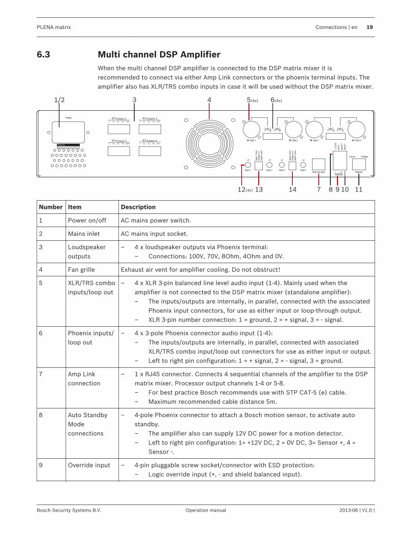
Multi channel DSP AmplifierWhen the multi channel DSP amplifier is connected to the DSP matrix mixer it isrecommended to connect via either Amp Link connectors or the phoenix terminal inputs. Theamplifier also has XLR/TRS combo inputs in case it will be used without the DSP matrix mixer.
Link/Act 100Mbps
Network
Override
Sen
sor
+
+1
2V
DC
Sen
sor
-
Bri
dge
3+
4In
put
3 S
ens
Inp
ut 4
Sen
s
Bri
dge
1+
2In
put
1 S
ens
Inp
ut 2
Sen
s
Power
Input 1 Input 2 Input 3 Input 4
Input 1 Input 2 Input 3 Input 4
Amp Link Input
Link 1 Link 2 Link 3 Link 4
Output 1
Output 3 Output 4
Output 20 4Ω 8Ω 70V 100V
0 4Ω 8Ω 70V 100V
0 4Ω 8Ω 70V 100V
0 4Ω 8Ω 70V 100V
0V
DC
Act
ive
1/2 3 4
7 8 9 111012(4x) 13 14
5(4x) 6(4x)
Number Item Description
1 Power on/off AC mains power switch.
2 Mains inlet AC mains input socket.
3 Loudspeakeroutputs
– 4 x loudspeaker outputs via Phoenix terminal:– Connections: 100V, 70V, 8Ohm, 4Ohm and 0V.
4 Fan grille Exhaust air vent for amplifier cooling. Do not obstruct!
5 XLR/TRS comboinputs/loop out
– 4 x XLR 3-pin balanced line level audio input (1-4). Mainly used when theamplifier is not connected to the DSP matrix mixer (standalone amplifier):– The inputs/outputs are internally, in parallel, connected with the associated
Phoenix input connectors, for use as either input or loop‑through output.– XLR 3-pin number connection: 1 = ground, 2 = + signal, 3 = - signal.
6 Phoenix inputs/loop out
– 4 x 3-pole Phoenix connector audio input (1-4):– The inputs/outputs are internally, in parallel, connected with associated
XLR/TRS combo input/loop out connectors for use as either input or output.– Left to right pin configuration: 1 = + signal, 2 = - signal, 3 = ground.
7 Amp Linkconnection
– 1 x RJ45 connector. Connects 4 sequential channels of the amplifier to the DSPmatrix mixer. Processor output channels 1-4 or 5-8.– For best practice Bosch recommends use with STP CAT‑5 (e) cable.– Maximum recommended cable distance 5m.
8 Auto StandbyModeconnections
– 4‑pole Phoenix connector to attach a Bosch motion sensor, to activate autostandby.– The amplifier also can supply 12V DC power for a motion detector.– Left to right pin configuration: 1= +12V DC, 2 = 0V DC, 3= Sensor +, 4 =
Sensor -.
9 Override input – 4-pin pluggable screw socket/connector with ESD protection:– Logic override input (+, - and shield balanced input).
6.3
PLENA matrix Connections | en 19
Bosch Security Systems B.V. Operation manual 2013-06 | V1.0 |

Number Item Description
10 Active – Contact closure to activate the “Override input”:– Use the 0 VDC from the sensor above as the common.
11 Network – RJ45 Ethernet communication socket:– Communication with the PLENA matrix GUI application.
!Warning!
The 12V DC power output (Auto Standby) connection should be only connected with
products in accordance with recommendations outlined in this manual.
Notice!
Recommended motion sensors for use with the auto standby mode are the Bosch range of
sensors.
For more information regarding Bosch security products contact your local Bosch Security
certified partner or go to www.boschsecurity.com for details.
Notice!
It is recommended that the cable used Amp Link cable is a high quality STP CAT‑5 (e) cable.
Amp Link cable distances should not exceed 5 meters per cable.
20 en | Connections PLENA matrix
2013-06 | V1.0 | Operation manual Bosch Security Systems B.V.
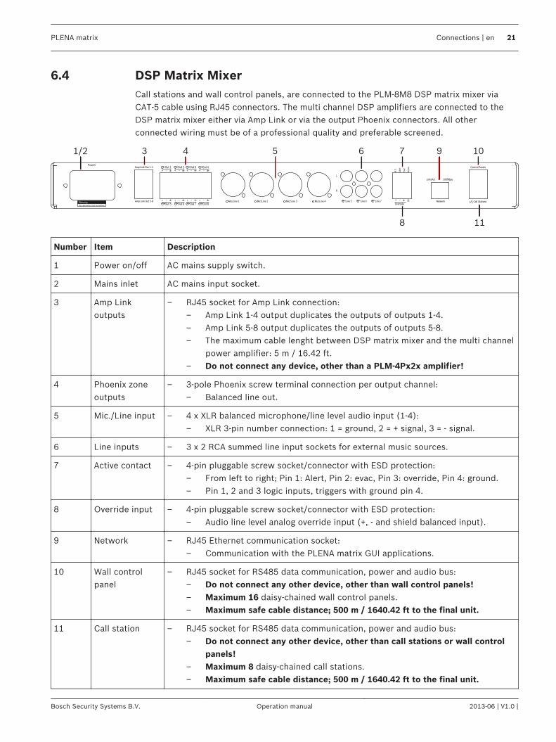
DSP Matrix MixerCall stations and wall control panels, are connected to the PLM‑8M8 DSP matrix mixer viaCAT‑5 cable using RJ45 connectors. The multi channel DSP amplifiers are connected to theDSP matrix mixer either via Amp Link or via the output Phoenix connectors. All otherconnected wiring must be of a professional quality and preferable screened.
Line 7 Network
Link/Act 100Mbps
Control Panels
Call Stations
Power
Mic/Line 4Mic/Line 3Mic/Line 2Mic/Line 1Amp Link Out 5-8
Amp Link Out 1-4
L
R
Line 5 Line 6
Out 1 Out 2 Out 3 Out 4
Out 5 Out 6 Out 7 Out 8
Ale
rt
Eva
c
Act
ive
0V
Override
N.C
.
1/2 3 4 5 6 7 9
8 11
10
Number Item Description
1 Power on/off AC mains supply switch.
2 Mains inlet AC mains input socket.
3 Amp Linkoutputs
– RJ45 socket for Amp Link connection:– Amp Link 1‑4 output duplicates the outputs of outputs 1‑4.– Amp Link 5‑8 output duplicates the outputs of outputs 5‑8.– The maximum cable lenght between DSP matrix mixer and the multi channel
power amplifier: 5 m / 16.42 ft.– Do not connect any device, other than a PLM‑4Px2x amplifier!
4 Phoenix zoneoutputs
– 3‑pole Phoenix screw terminal connection per output channel:– Balanced line out.
5 Mic./Line input – 4 x XLR balanced microphone/line level audio input (1-4):– XLR 3‑pin number connection: 1 = ground, 2 = + signal, 3 = - signal.
6 Line inputs – 3 x 2 RCA summed line input sockets for external music sources.
7 Active contact – 4‑pin pluggable screw socket/connector with ESD protection:– From left to right; Pin 1: Alert, Pin 2: evac, Pin 3: override, Pin 4: ground.– Pin 1, 2 and 3 logic inputs, triggers with ground pin 4.
8 Override input – 4-pin pluggable screw socket/connector with ESD protection:– Audio line level analog override input (+, - and shield balanced input).
9 Network – RJ45 Ethernet communication socket:– Communication with the PLENA matrix GUI applications.
10 Wall controlpanel
– RJ45 socket for RS485 data communication, power and audio bus:– Do not connect any other device, other than wall control panels!– Maximum 16 daisy‑chained wall control panels.– Maximum safe cable distance; 500 m / 1640.42 ft to the final unit.
11 Call station – RJ45 socket for RS485 data communication, power and audio bus:– Do not connect any other device, other than call stations or wall control
panels!– Maximum 8 daisy‑chained call stations.– Maximum safe cable distance; 500 m / 1640.42 ft to the final unit.
6.4
PLENA matrix Connections | en 21
Bosch Security Systems B.V. Operation manual 2013-06 | V1.0 |
Notice!
Hardware settings cannot be overruled or changed by the PC GUI application software.
See also– DSP Matrix Mixer and Amplifiers, page 13
22 en | Connections PLENA matrix
2013-06 | V1.0 | Operation manual Bosch Security Systems B.V.
ConfigurationCall Station DIP switch settings, page 23Wall Control Panel DIP switch settings, page 24Multi Channel DSP Amplifier settings, page 25DSP matrix mixer PC GUI, page 26Multi Channel DSP Amplifier PC GUI, page 28
Call StationConfiguration of zone groups, printable labels for the call stations and chimes is done via thePC software GUI. Refer to DSP matrix mixer PC GUI, page 26.
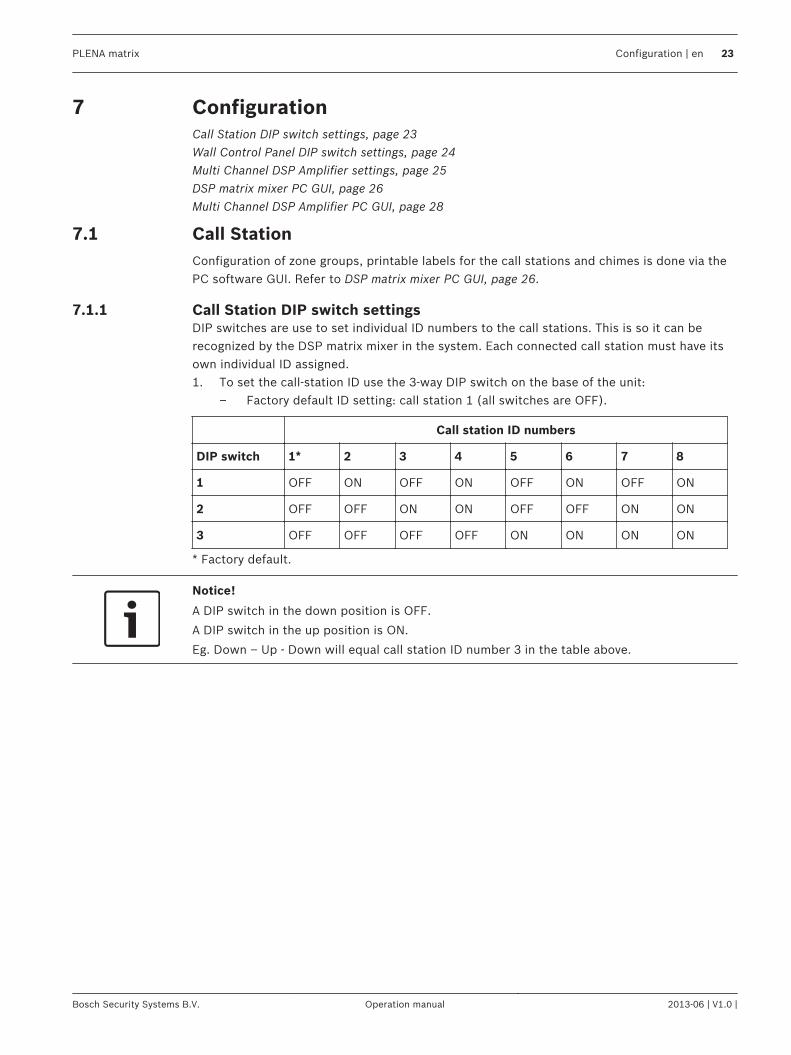
Call Station DIP switch settingsDIP switches are use to set individual ID numbers to the call stations. This is so it can berecognized by the DSP matrix mixer in the system. Each connected call station must have itsown individual ID assigned.1. To set the call-station ID use the 3‑way DIP switch on the base of the unit:
– Factory default ID setting: call station 1 (all switches are OFF).
Call station ID numbers
DIP switch 1* 2 3 4 5 6 7 8
1 OFF ON OFF ON OFF ON OFF ON
2 OFF OFF ON ON OFF OFF ON ON
3 OFF OFF OFF OFF ON ON ON ON
* Factory default.
Notice!
A DIP switch in the down position is OFF.
A DIP switch in the up position is ON.
Eg. Down – Up - Down will equal call station ID number 3 in the table above.
7
7.1
7.1.1
PLENA matrix Configuration | en 23
Bosch Security Systems B.V. Operation manual 2013-06 | V1.0 |
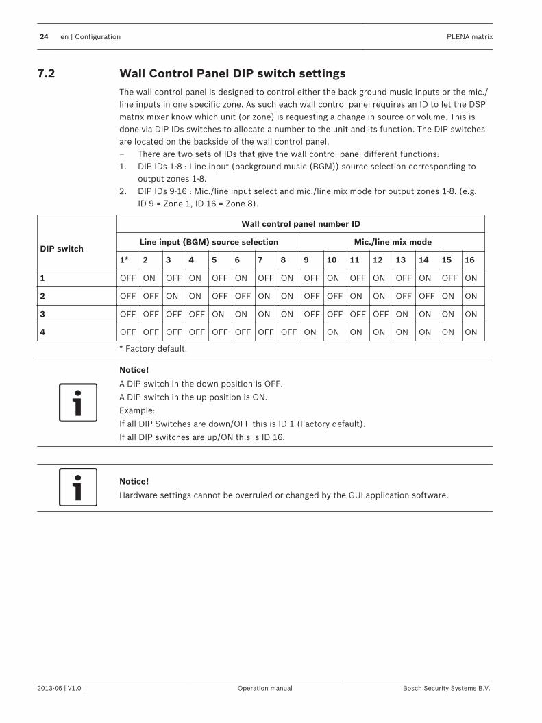
Wall Control Panel DIP switch settingsThe wall control panel is designed to control either the back ground music inputs or the mic./line inputs in one specific zone. As such each wall control panel requires an ID to let the DSPmatrix mixer know which unit (or zone) is requesting a change in source or volume. This isdone via DIP IDs switches to allocate a number to the unit and its function. The DIP switchesare located on the backside of the wall control panel.– There are two sets of IDs that give the wall control panel different functions:1. DIP IDs 1‑8 : Line input (background music (BGM)) source selection corresponding to
output zones 1‑8.2. DIP IDs 9‑16 : Mic./line input select and mic./line mix mode for output zones 1‑8. (e.g.
ID 9 = Zone 1, ID 16 = Zone 8).
DIP switch
Wall control panel number ID
Line input (BGM) source selection Mic./line mix mode
1* 2 3 4 5 6 7 8 9 10 11 12 13 14 15 16
1 OFF ON OFF ON OFF ON OFF ON OFF ON OFF ON OFF ON OFF ON
2 OFF OFF ON ON OFF OFF ON ON OFF OFF ON ON OFF OFF ON ON
3 OFF OFF OFF OFF ON ON ON ON OFF OFF OFF OFF ON ON ON ON
4 OFF OFF OFF OFF OFF OFF OFF OFF ON ON ON ON ON ON ON ON
* Factory default.
Notice!
A DIP switch in the down position is OFF.
A DIP switch in the up position is ON.
Example:
If all DIP Switches are down/OFF this is ID 1 (Factory default).
If all DIP switches are up/ON this is ID 16.
Notice!
Hardware settings cannot be overruled or changed by the GUI application software.
7.2
24 en | Configuration PLENA matrix
2013-06 | V1.0 | Operation manual Bosch Security Systems B.V.
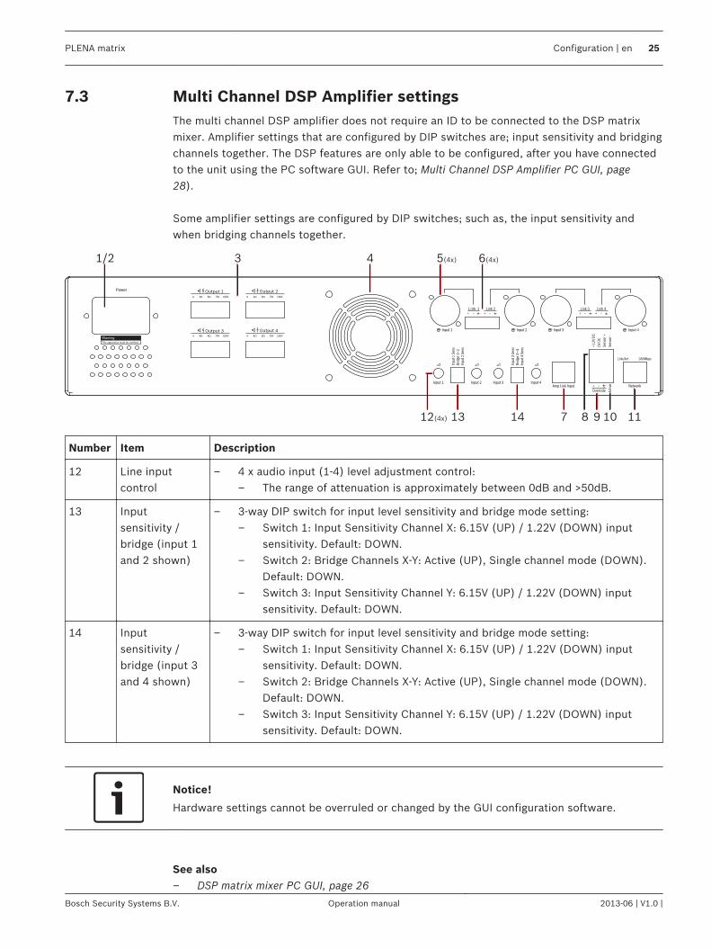
Multi Channel DSP Amplifier settingsThe multi channel DSP amplifier does not require an ID to be connected to the DSP matrixmixer. Amplifier settings that are configured by DIP switches are; input sensitivity and bridgingchannels together. The DSP features are only able to be configured, after you have connectedto the unit using the PC software GUI. Refer to; Multi Channel DSP Amplifier PC GUI, page28). Some amplifier settings are configured by DIP switches; such as, the input sensitivity andwhen bridging channels together.
Link/Act 100Mbps
Network
Override
Sen
sor
+
+1
2V
DC
Sen
sor
-
Bri
dge
3+
4In
put
3 S
ens
Inp
ut 4
Sen
s
Bri
dge
1+
2In
put
1 S
ens
Inp
ut 2
Sen
s
Power
Input 1 Input 2 Input 3 Input 4
Input 1 Input 2 Input 3 Input 4
Amp Link Input
Link 1 Link 2 Link 3 Link 4
Output 1
Output 3 Output 4
Output 20 4Ω 8Ω 70V 100V
0 4Ω 8Ω 70V 100V
0 4Ω 8Ω 70V 100V
0 4Ω 8Ω 70V 100V
0V
DC
Act
ive
1/2 3 4
7 8 9 111012(4x) 13 14
5(4x) 6(4x)
Number Item Description
12 Line inputcontrol
– 4 x audio input (1-4) level adjustment control:– The range of attenuation is approximately between 0dB and >50dB.
13 Inputsensitivity /bridge (input 1and 2 shown)
– 3‑way DIP switch for input level sensitivity and bridge mode setting:– Switch 1: Input Sensitivity Channel X: 6.15V (UP) / 1.22V (DOWN) input
sensitivity. Default: DOWN.– Switch 2: Bridge Channels X-Y: Active (UP), Single channel mode (DOWN).
Default: DOWN.– Switch 3: Input Sensitivity Channel Y: 6.15V (UP) / 1.22V (DOWN) input
sensitivity. Default: DOWN.
14 Inputsensitivity /bridge (input 3and 4 shown)
– 3‑way DIP switch for input level sensitivity and bridge mode setting:– Switch 1: Input Sensitivity Channel X: 6.15V (UP) / 1.22V (DOWN) input
sensitivity. Default: DOWN.– Switch 2: Bridge Channels X-Y: Active (UP), Single channel mode (DOWN).
Default: DOWN.– Switch 3: Input Sensitivity Channel Y: 6.15V (UP) / 1.22V (DOWN) input
sensitivity. Default: DOWN.
Notice!
Hardware settings cannot be overruled or changed by the GUI configuration software.
See also– DSP matrix mixer PC GUI, page 26
7.3
PLENA matrix Configuration | en 25
Bosch Security Systems B.V. Operation manual 2013-06 | V1.0 |

DSP matrix mixer PC GUIAll audio set up configurations for the DSP matrix mixer are done via the PC software GUI.With the DSP matrix mixer PC GUI: audio input levels; audio output levels and controls couldbe set via the connected PC.
Notice!
It is impossible to configure the DSP matrix mixer's advance DSP settings without this PC GUI
installed and connected!
Refer to PC GUI software, page 16 installation to install the PC GUI, if needed.
Proceed as follows:
Notice!
Changes and updates to this procedure are available in the software down load file.
1. Complete the installation of the PC GUI software. Refer to PC GUI application software
installation, page 16 for more information.2. Open the PC GUI software program.3. The DSP PC GUI configuration program starts and the user screen should appear:
– An offline configuration for the DSP matrix mixer can be made and saved onto thePC, without connection to the unit. This can be saved and uploaded at a later time, ifrequired.
4. To make a connection to the DSP matrix mixer, make sure that an Ethernet cable isconnected to the network port of the DSP matrix mixer.
5. To connect to the unit via PC GUI:– In the Tool bar - Click “Device” and then click “Connect”. The “Connect to target”
window will open.Note: If the “Connect” is grayed out. Please enter the administrator password/hardware password under the Admin menu or contact the installer assistance.
– Click “Search/Refresh” to discover the active units connected to the network. Selectthe unit you wish to control. Click on which way you would like the data to flowduring connection; either “Read configuration from device” or “Write configurationto device” buttons.Read configuration from device : This will read or extract the settings from theselected unit and display them on your PC GUI. You can then control the system.Write configuration to device: This will send the configuration that is on the PC GUIto the unit.
– You are now online. The green “Online” Light should be illuminated on the GUIscreen.
Notice!
When selecting “Write configuration to device”. You will clear and wipe all existing setting on
the device.
There is no undo button for this after the task has been completed.
6. Changing details of the unit:– To change the unit from DHCP to a static IP configuration, follow the procedure
above to open the connect to target window. Once in the unit is selected, you canchange:
7.4
26 en | Configuration PLENA matrix
2013-06 | V1.0 | Operation manual Bosch Security Systems B.V.
– Turn DHCP on/off.– Set a static IP address.– Change the device name for easy identification in larger systems.
7. The GUI should now be connected and online in the “User page” where inputs can bemixed into different zones.
8. To access the DSP configuration page go to “Config” in the menu bar and select “DSPsetup”.
Notice!
For more information regarding the operation of features within the GUI, please read the GUI
operation document.
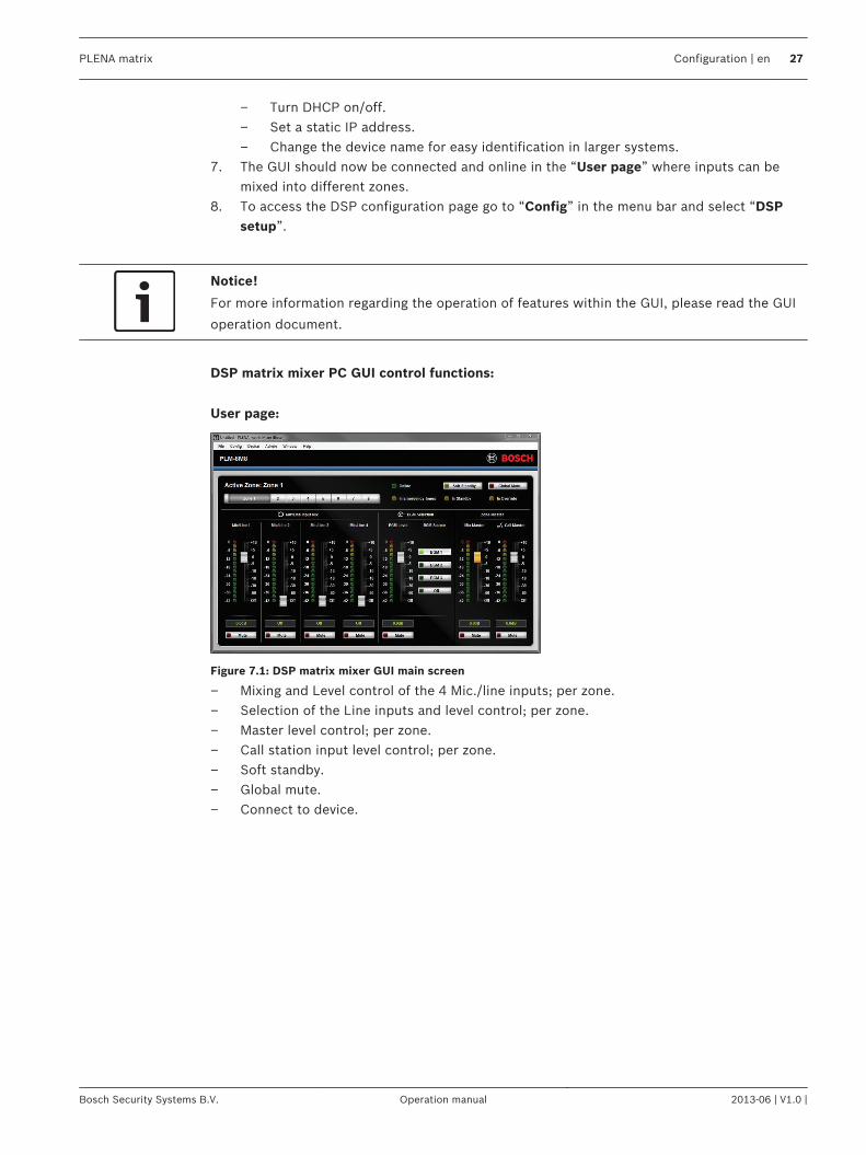
DSP matrix mixer PC GUI control functions:
User page:
Figure 7.1: DSP matrix mixer GUI main screen
– Mixing and Level control of the 4 Mic./line inputs; per zone.– Selection of the Line inputs and level control; per zone.– Master level control; per zone.– Call station input level control; per zone.– Soft standby.– Global mute.– Connect to device.
PLENA matrix Configuration | en 27
Bosch Security Systems B.V. Operation manual 2013-06 | V1.0 |
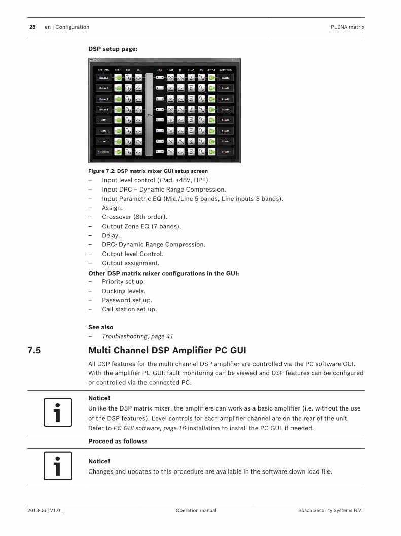
DSP setup page:
Figure 7.2: DSP matrix mixer GUI setup screen
– Input level control (iPad, +48V, HPF).– Input DRC – Dynamic Range Compression.– Input Parametric EQ (Mic./Line 5 bands, Line inputs 3 bands).– Assign.– Crossover (8th order).– Output Zone EQ (7 bands).– Delay.– DRC- Dynamic Range Compression.– Output level Control.– Output assignment.
Other DSP matrix mixer configurations in the GUI:– Priority set up.– Ducking levels.– Password set up.– Call station set up.
See also– Troubleshooting, page 41
Multi Channel DSP Amplifier PC GUIAll DSP features for the multi channel DSP amplifier are controlled via the PC software GUI.With the amplifier PC GUI: fault monitoring can be viewed and DSP features can be configuredor controlled via the connected PC.
Notice!
Unlike the DSP matrix mixer, the amplifiers can work as a basic amplifier (i.e. without the use
of the DSP features). Level controls for each amplifier channel are on the rear of the unit.
Refer to PC GUI software, page 16 installation to install the PC GUI, if needed.
Proceed as follows:
Notice!
Changes and updates to this procedure are available in the software down load file.
7.5
28 en | Configuration PLENA matrix
2013-06 | V1.0 | Operation manual Bosch Security Systems B.V.

1. Complete the installation of the PC GUI software. Refer to PC GUI application softwareinstallation, page 16 for more information.
2. Open the PC GUI software program.3. The amplifier PC GUI program should open and the user screen should appear:
– An offline configuration of the amplifier can be made without connection to a DSPmatrix mixer, and uploaded to the DSP matrix mixer at a later time (optional).
4. To make a connection to the hardware, make sure that an Ethernet cable is connectedbetween the PC and to the network port of the amplifier.
5. To connect to the unit via PC GUI:– In the Tool bar - Click “Device” and then click “Connect”. The “Connect to target”
window will open.Note: If the “Connect” is grayed out. Please enter the administrator password/hardware password under the Admin menu or contact the installer assistance.
– Click “Search/Refresh” to discover the active units connected to the network. Selectthe unit you wish to control. Click on which way you would like the data to flowduring connection; either “Read configuration from device” or “Write configurationto device” buttons.Read configuration from device : This will read or extract the settings from theselected unit and display them on your PC GUI. You can then control the system.Write configuration to device: This will send the configuration that is on the PC GUIto the unit.Note: This will overwrite all the current settings in the device.
– You are now online. The green “Online” Light should be illuminated on the GUIscreen.
Notice!
When selecting “Write configuration to device”. You will clear and wipe all existing setting on
the device.
There is no undo button for this after the task has been completed.
6. Changing details of the unit:– To change the unit from DHCP to a static IP configuration, follow the procedure
above to open the connect to target window. Once in the unit is selected, you canchange:
– Turn DHCP on/off.– Set a static IP address.– Change the device name for easy identification in larger systems.
7. The GUI should now be connected and online in the “User page” where inputs can bemixed into different zones.
8. To access the DSP configuration page go to “Config” in the menu bar and select “DSPsetup”.
Notice!
For more information regarding the operation of features within the PC GUI, please read the
PC GUI operation document in the help menu of the PC GUI.
Refer to DSP matrix mixer PC GUI, page 26 when use the amplifier connected to the DSP
matrix mixer.
PLENA matrix Configuration | en 29
Bosch Security Systems B.V. Operation manual 2013-06 | V1.0 |
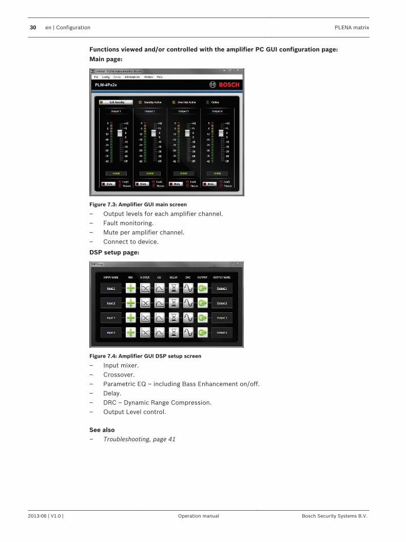
Functions viewed and/or controlled with the amplifier PC GUI configuration page:
Main page:
Figure 7.3: Amplifier GUI main screen
– Output levels for each amplifier channel.– Fault monitoring.– Mute per amplifier channel.– Connect to device.
DSP setup page:
Figure 7.4: Amplifier GUI DSP setup screen
– Input mixer.– Crossover.– Parametric EQ – including Bass Enhancement on/off.– Delay.– DRC – Dynamic Range Compression.– Output Level control.
See also– Troubleshooting, page 41
30 en | Configuration PLENA matrix
2013-06 | V1.0 | Operation manual Bosch Security Systems B.V.

Amplifier Bridging Configuration1. Set the Bridge DIP switch (13 and 14) on the rear of the unit to the ON position (1+2 or
3+4).2. Restart the amplifier, as the value of the DIP switches is only read during powering up.3. Wiring the outputs; The two channels being bridged together should have the commons
(0V) connected together, and then either the 4/8/70V/100V taps off the two channels arethen used for the + ve and the – ve to the speaker cable.
!Warning!
Bridging the 70V and 100V lines, the voltage will be 140V and 200V respectively.
!
Caution!
Be sure that the higher voltage does not create a problem for the speakers used:
If any problem exists, this may be solved with the use of a 2:1 step down transformer
7.5.1
PLENA matrix Configuration | en 31
Bosch Security Systems B.V. Operation manual 2013-06 | V1.0 |
OperationCall stations and wall control panels can only operate when connected to the DSP matrixmixer and individual IDs have been set via the DIP switches on the units. Refer to Call StationDIP switch settings, page 23 and Wall Control Panel DIP switch settings, page 24.The multi channel DSP amplifier can operate both as a standalone amplifier or connected tothe DSP matrix mixer.
Start1. Check that all connections have been made to relevant units in the system including wall
control panels and call stations.2. Power on the DSP matrix mixer followed by the amplifiers.3. Check that the power LED are illuminated on the front of the DSP matrix mixer and
amplifier(s) (19” rack unit(s)).4. Check that the RS485 LED is flashing for connections to the wall control panels and call
stations.5. Make sure that the level controls on the rear of the amplifier are set to the desired level.6. For use with the PC GUI software, Click “Device” from the menu bar, and then
“Connect”. Refer to PC GUI software, page 16.– If the above steps have been followed the system should be in its last mode of operation.
However, if this is the initial power‑up of the system, it will be obviously be in its factorydefault state.
– If all of the above steps have been followed and the system is not working correctly, referto the Troubleshooting, page 41 section of this manual.
Continue with one of the following chapters:– Call Station, page 33– Wall Control Panel, page 35– Multi Channel DSP Amplifier, page 37– DSP Matrix Mixer, page 39
8
8.1
32 en | Operation PLENA matrix
2013-06 | V1.0 | Operation manual Bosch Security Systems B.V.
Call StationThe call station is used to make announcements in pre‑selected loudspeaker zones.
Notice!
Upon start up, the call stations will need to be identified by the processor. During this period
the LEDs will flash in a rotating sequence; once this is complete the system is ready. Allow
approx. 15 seconds before attempting an announcement.
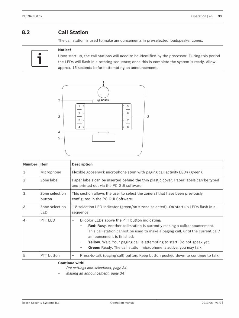
1
3 3
2
4
5
Number Item Description
1 Microphone Flexible gooseneck microphone stem with paging call activity LEDs (green).
2 Zone label Paper labels can be inserted behind the thin plastic cover. Paper labels can be typedand printed out via the PC GUI software.
3 Zone selectionbutton
This section allows the user to select the zone(s) that have been previouslyconfigured in the PC GUI Software.
3 Zone selectionLED
1‑8 selection LED indicator (green/on = zone selected). On start up LEDs flash in asequence.
4 PTT LED – Bi‑color LEDs above the PTT button indicating:– Red: Busy. Another call-station is currently making a call/announcement.
This call-station cannot be used to make a paging call, until the current call/announcement is finished.
– Yellow: Wait. Your paging call is attempting to start. Do not speak yet.– Green: Ready. The call station microphone is active, you may talk.
5 PTT button – Press‑to‑talk (paging call) button. Keep button pushed down to continue to talk.
Continue with:– Pre-settings and selections, page 34– Making an announcement, page 34
8.2
PLENA matrix Operation | en 33
Bosch Security Systems B.V. Operation manual 2013-06 | V1.0 |
Pre-settings and selectionsThe following pre‑selections and settings have to be done by the DSP matrix mixer PC GUIapplication at configuration of the system. Refer to DSP matrix mixer PC GUI, page 26– Setting button functions - zone groups per call station (see PC GUI help file for more
information).– Chime generation (enable/disable).– Microphone gain control.– The call-station ID setting is pre-defined at configuration. Refer to Call Station DIP switch
settings, page 23.
Making an announcement1. Select zone(s) by touching the numbered capacitive zone selection areas:
– The zone selection LED indicates the zone group to which the announcement isdistributed.
– To deselect the zone group, touch the capacitive area again (LED is off).2. Multiple zone groups can be selected by continuing to use the numbered capacitive touch
areas. Push the press‑to‑talk (PTT) button:– When the LED above the PPT button goes green, you are ready to talk. Refer to Call
Station, page 33.– Only one call-station in the system is able to make an announcement at one time.
Notice!
Use slow deliberate touches on the capacitive touch areas on products. Excessively fast
tapping may not be recognized by the unit.
A good rule when making an announcement through the call station is to keep at least one
hands distance away from the microphone. This will reduce popping noises and distortion in
the system.
8.2.1
8.2.2
34 en | Operation PLENA matrix
2013-06 | V1.0 | Operation manual Bosch Security Systems B.V.
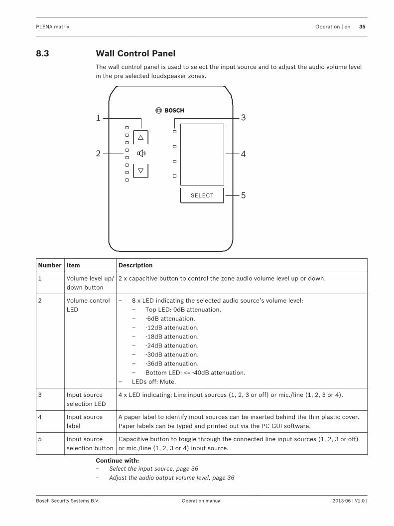
Wall Control PanelThe wall control panel is used to select the input source and to adjust the audio volume levelin the pre‑selected loudspeaker zones.
SELECT
2
1 3
4
5
Number Item Description
1 Volume level up/down button
2 x capacitive button to control the zone audio volume level up or down.
2 Volume controlLED
– 8 x LED indicating the selected audio source’s volume level:– Top LED: 0dB attenuation.– -6dB attenuation.– -12dB attenuation.– -18dB attenuation.– -24dB attenuation.– -30dB attenuation.– -36dB attenuation.– Bottom LED: <= -40dB attenuation.
– LEDs off: Mute.
3 Input sourceselection LED
4 x LED indicating; Line input sources (1, 2, 3 or off) or mic./line (1, 2, 3 or 4).
4 Input sourcelabel
A paper label to identify input sources can be inserted behind the thin plastic cover.Paper labels can be typed and printed out via the PC GUI software.
5 Input sourceselection button
Capacitive button to toggle through the connected line input sources (1, 2, 3 or off)or mic./line (1, 2, 3 or 4) input source.
Continue with:– Select the input source, page 36– Adjust the audio output volume level, page 36
8.3
PLENA matrix Operation | en 35
Bosch Security Systems B.V. Operation manual 2013-06 | V1.0 |
Select the input source1. Select the input source with the capacitive touch button labelled “Select”:
– The input source selection LED indicates the input source or off.– NOTICE: The source (microphone inputs or line inputs), ID and zone selection are
pre‑defined at configuration. Refer to Wall Control Panel DIP switch settings, page 24.
Adjust the audio output volume level1. Press the capacitive touch buttons up or down arrows to adjust audio level:
– One touch per 3 dB step.2. The volume control LED indicates the audio output volume level:
– The maximum level indicated is dependent upon the predefined maximum allowablelevel that is set in the PC GUI (DSP setup output level).
Notice!
Use slow deliberate touches to the capacitive touch areas on products. Excessively fast
tapping may not be recognized by the unit.
Notice!
The level will increase or decrease 3dB for every button press of the arrows, and the LED is
6dB per step. Therefore it will sometimes require 2 pushes to see the next LED illuminate.
8.3.1
8.3.2
36 en | Operation PLENA matrix
2013-06 | V1.0 | Operation manual Bosch Security Systems B.V.

Multi Channel DSP AmplifierThe multi channel amplifier’s DSP is able to be used to process audio signals for up to 4zones. The amplifiers can be used either with or without the DSP functionality.The amplifier can be used standalone or connected to the DSP matrix mixer.Refer to DSP Matrix Mixer, page 21 if the amplifier is only connected to the DSP matrix mixerand loudspeaker output zones.
CH CH CH CH
Signal/Clip
Fault
1 2
Number Item Description
1 Power on LED Flashes (green) during power up. It becomes solid (green) as soon the amplifier isready-for-use.
2 Input signalLEDs
– Two LEDs per amplifier input channel (4x) indicating:– Protect/fault. On (red), indicates an amplifier fault. Refer to Troubleshooting,
page 41 section.– Signal presence/clip bi-color LED: On, when the applied audio input signal is
-40dB from clip (green), -3dB from clip (amber), 0dB full output power(red).
Standalone without connection to the PC GUIAfter following the guide on setting up the input sensitivity and bridging (if required).1. Turn on the amplifier.2. Use level controls on the rear of the unit to set desired output level (The factory preset
configuration is input 1 is routed to output 1 etc. All internal levels are set to unity gain).3. If usage with the auto standby mode is required, the preset time out is 1 hour.
With DSP / PC GUI functionalityAfter following the guide on setting the input sensitivity and bridging (if required).1. Turn on the amplifier.2. Use level controls on the rear of the unit, to set desired output level:
– Usually these level controls are set to full, as you can adjust the levels down withinthe PC GUI.
3. Open the PC GUI program and click on "Device" in the menu bar, and then click"Connect":– Refer to Multi Channel DSP Amplifier PC GUI, page 28 for configuration details.
4. If required, more information on using the PC GUI can be found in the help menu.– Refer to Multi Channel DSP Amplifier PC GUI, page 28; for DSP features.
Notice!
Hardware settings (controls and switches) cannot be overruled or changed by the DSP matrix
mixer and amplifier PC GUI configuration software.
8.4
PLENA matrix Operation | en 37
Bosch Security Systems B.V. Operation manual 2013-06 | V1.0 |
The following operations can be done when using the amplifier hardware in either mode oroperation:– Activate the active override audio input function, page 38.– Activate the amplifier auto standby, page 38.
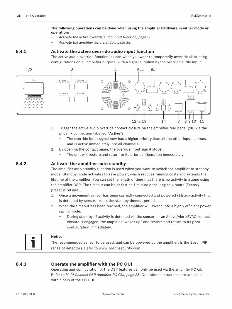
Activate the active override audio input functionThe active audio override function is used when you want to temporarily override all existingconfigurations on all amplifier outputs, with a signal supplied by the override audio input.
Link/Act 100Mbps
Network
Override
Sen
sor
+
+1
2V
DC
Sen
sor
-
Bri
dge
3+
4In
put
3 S
ens
Inp
ut 4
Sen
s
Bri
dge
1+
2In
put
1 S
ens
Inp
ut 2
Sen
s
Power
Input 1 Input 2 Input 3 Input 4
Input 1 Input 2 Input 3 Input 4
Amp Link Input
Link 1 Link 2 Link 3 Link 4
Output 1
Output 3 Output 4
Output 20 4Ω 8Ω 70V 100V
0 4Ω 8Ω 70V 100V
0 4Ω 8Ω 70V 100V
0 4Ω 8Ω 70V 100V
0V
DC
Act
ive
1/2 3 4
7 8 9 111012(4x) 13 14
5(4x) 6(4x)
1. Trigger the active audio override contact closure on the amplifier rear panel (10) via thephoenix connection labelled “Active”:– The override input signal now has a higher priority than all the other input sources,
and is active immediately into all channels.2. By opening the contact again, the override input signal stops:
– The unit will restore and return to its prior configuration immediately.
Activate the amplifier auto standbyThe amplifier auto standby function is used when you want to switch the amplifier to standbymode. Standby mode activates to save power, which reduces running costs and extends thelifetime of the amplifier. You can set the length of time that there is no activity in a zone usingthe amplifier DSP. The timeout can be as fast as 1 minute or as long as 4 hours (Factorypreset is 60 min.).1. Once a movement sensor has been correctly connected and powered (8); any activity that
is detected by sensor, resets the standby timeout period.2. When the timeout has been reached, the amplifier will switch into a highly efficient power
saving mode.– During standby, if activity is detected via the sensor, or an Active/Alert/EVAC contact
closure is engaged; the amplifier “wakes up” and restore and return to its priorconfiguration immediately.
Notice!
The recommended sensor to be used, and can be powered by the amplifier, is the Bosch PIR
range of detectors. Refer to www.boschsecurity.com.
Operate the amplifier with the PC GUIOperating and configuration of the DSP features can only be used via the amplifier PC GUI.Refer to Multi Channel DSP Amplifier PC GUI, page 28. Operation instructions are availablewithin help of the PC GUI.
8.4.1
8.4.2
8.4.3
38 en | Operation PLENA matrix
2013-06 | V1.0 | Operation manual Bosch Security Systems B.V.
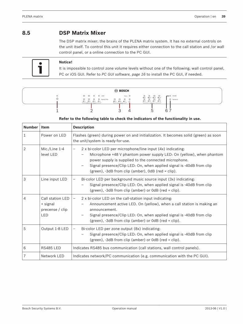
DSP Matrix MixerThe DSP matrix mixer; the brains of the PLENA matrix system. It has no external controls onthe unit itself. To control this unit it requires either connection to the call station and /or wallcontrol panel, or a online connection to the PC GUI.
Notice!
It is impossible to control zone volume levels without one of the following; wall control panel,
PC or iOS GUI. Refer to PC GUI software, page 16 to install the PC GUI, if needed.
Mic/Line Inputs
+48V
Line Inputs
Busy
NetworkSignal/Clip
Outputs
1 2 3 4 5 6 7
Refer to the following table to check the indicators of the functionality in use.
Number Item Description
1 Power on LED Flashes (green) during power on and initialization. It becomes solid (green) as soonthe unit/system is ready-for-use.
2 Mic./Line 1‑4level LED
– 2 x bi‑color LED per microphone/line input (4x) indicating:– Microphone +48 V phantom power supply LED: On (yellow), when phantom
power supply is supplied to the connected microphone.– Signal presence/Clip LED: On, when applied signal is -40dB from clip
(green), -3dB from clip (amber), 0dB (red = clip).
3 Line input LED – Bi‑color LED per background music source input (3x) indicating:– Signal presence/Clip LED: On, when applied signal is -40dB from clip
(green), -3dB from clip (amber) or 0dB (red = clip).
4 Call station LED+ signalprecense / clipLED
– 2 x bi‑color LED on the call-station input indicating:– Announcement active LED. On (yellow), when a call station is making an
announcement.– Signal presence/Clip LED: On, when applied signal is -40dB from clip
(green), -3dB from clip (amber) or 0dB (red = clip).
5 Output 1‑8 LED – Bi‑color LED per zone output (8x) indicating:– Signal presence/Clip LED: On, when applied signal is -40dB from clip
(green), -3dB from clip (amber) or 0dB (red = clip).
6 RS485 LED Indicates RS485 bus communication (call stations, wall control panels).
7 Network LED Indicates network/PC communication (e.g. communication with the PC GUI).
8.5
PLENA matrix Operation | en 39
Bosch Security Systems B.V. Operation manual 2013-06 | V1.0 |
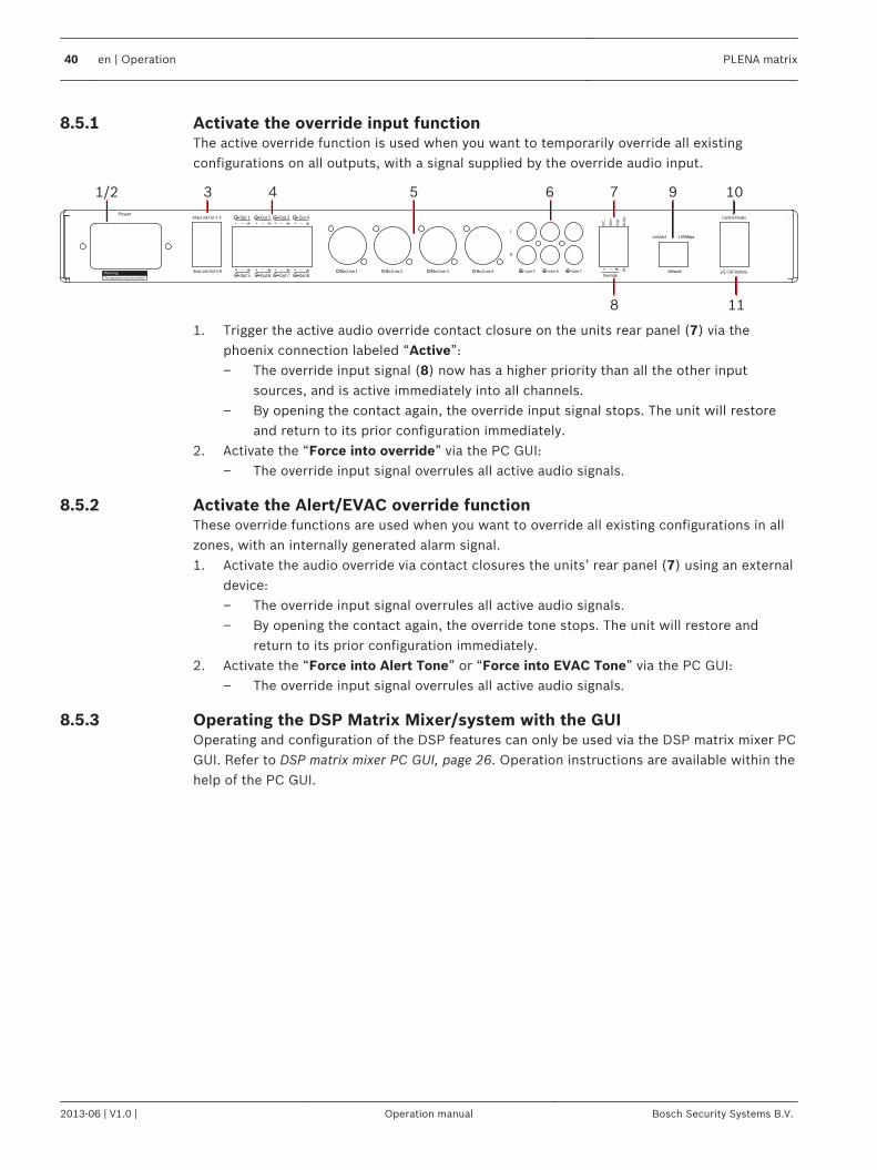
Activate the override input functionThe active override function is used when you want to temporarily override all existingconfigurations on all outputs, with a signal supplied by the override audio input.
Line 7 Network
Link/Act 100Mbps
Control Panels
Call Stations
Power
Mic/Line 4Mic/Line 3Mic/Line 2Mic/Line 1Amp Link Out 5-8
Amp Link Out 1-4
L
R
Line 5 Line 6
Out 1 Out 2 Out 3 Out 4
Out 5 Out 6 Out 7 Out 8
Ale
rt
Eva
c
Act
ive
0V
Override
N.C
.
1/2 3 4 5 6 7 9
8 11
10
1. Trigger the active audio override contact closure on the units rear panel (7) via thephoenix connection labeled “Active”:– The override input signal (8) now has a higher priority than all the other input
sources, and is active immediately into all channels.– By opening the contact again, the override input signal stops. The unit will restore
and return to its prior configuration immediately.2. Activate the “Force into override” via the PC GUI:
– The override input signal overrules all active audio signals.
Activate the Alert/EVAC override functionThese override functions are used when you want to override all existing configurations in allzones, with an internally generated alarm signal.1. Activate the audio override via contact closures the units’ rear panel (7) using an external
device:– The override input signal overrules all active audio signals.– By opening the contact again, the override tone stops. The unit will restore and
return to its prior configuration immediately.2. Activate the “Force into Alert Tone” or “Force into EVAC Tone” via the PC GUI:
– The override input signal overrules all active audio signals.
Operating the DSP Matrix Mixer/system with the GUIOperating and configuration of the DSP features can only be used via the DSP matrix mixer PCGUI. Refer to DSP matrix mixer PC GUI, page 26. Operation instructions are available within thehelp of the PC GUI.
8.5.1
8.5.2
8.5.3
40 en | Operation PLENA matrix
2013-06 | V1.0 | Operation manual Bosch Security Systems B.V.
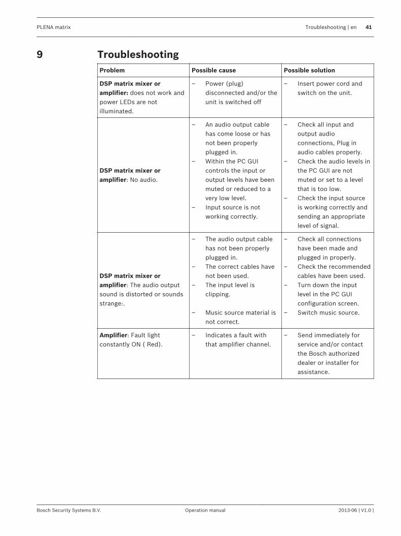
TroubleshootingProblem Possible cause Possible solution
DSP matrix mixer oramplifier: does not work andpower LEDs are notilluminated.
– Power (plug)disconnected and/or theunit is switched off
– Insert power cord andswitch on the unit.
DSP matrix mixer oramplifier: No audio.
– An audio output cablehas come loose or hasnot been properlyplugged in.
– Within the PC GUIcontrols the input oroutput levels have beenmuted or reduced to avery low level.
– Input source is notworking correctly.
– Check all input andoutput audioconnections, Plug inaudio cables properly.
– Check the audio levels inthe PC GUI are notmuted or set to a levelthat is too low.
– Check the input sourceis working correctly andsending an appropriatelevel of signal.
DSP matrix mixer oramplifier: The audio outputsound is distorted or soundsstrange:.
– The audio output cablehas not been properlyplugged in.
– The correct cables havenot been used.
– The input level isclipping.
– Music source material isnot correct.
– Check all connectionshave been made andplugged in properly.
– Check the recommendedcables have been used.
– Turn down the inputlevel in the PC GUIconfiguration screen.
– Switch music source.
Amplifier: Fault lightconstantly ON ( Red).
– Indicates a fault withthat amplifier channel.
– Send immediately forservice and/or contactthe Bosch authorizeddealer or installer forassistance.
9
PLENA matrix Troubleshooting | en 41
Bosch Security Systems B.V. Operation manual 2013-06 | V1.0 |
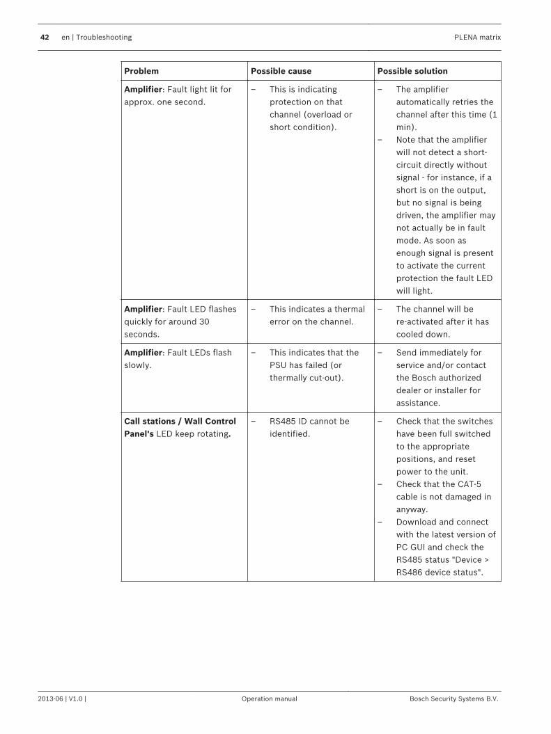
Problem Possible cause Possible solution
Amplifier: Fault light lit forapprox. one second.
– This is indicatingprotection on thatchannel (overload orshort condition).
– The amplifierautomatically retries thechannel after this time (1min).
– Note that the amplifierwill not detect a short-circuit directly withoutsignal - for instance, if ashort is on the output,but no signal is beingdriven, the amplifier maynot actually be in faultmode. As soon asenough signal is presentto activate the currentprotection the fault LEDwill light.
Amplifier: Fault LED flashesquickly for around 30seconds.
– This indicates a thermalerror on the channel.
– The channel will bere‑activated after it hascooled down.
Amplifier: Fault LEDs flashslowly.
– This indicates that thePSU has failed (orthermally cut‑out).
– Send immediately forservice and/or contactthe Bosch authorizeddealer or installer forassistance.
Call stations / Wall ControlPanel's LED keep rotating.
– RS485 ID cannot beidentified.
– Check that the switcheshave been full switchedto the appropriatepositions, and resetpower to the unit.
– Check that the CAT‑5cable is not damaged inanyway.
– Download and connectwith the latest version ofPC GUI and check theRS485 status "Device >RS486 device status".
42 en | Troubleshooting PLENA matrix
2013-06 | V1.0 | Operation manual Bosch Security Systems B.V.
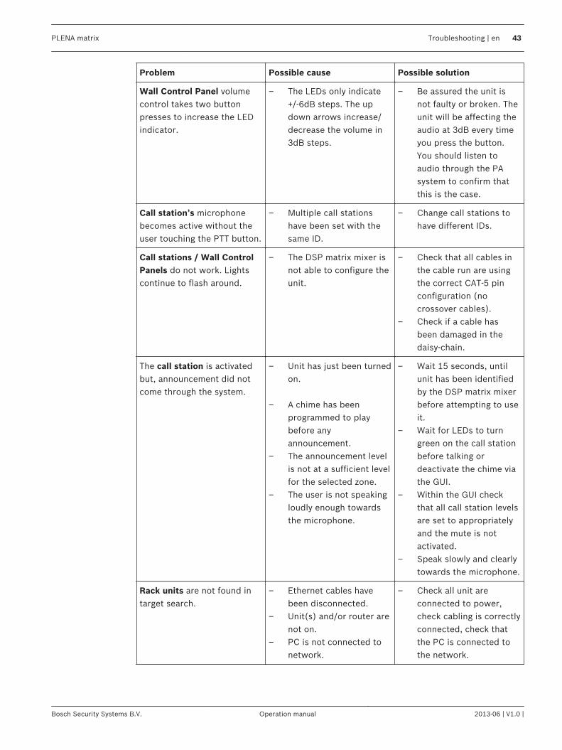
Problem Possible cause Possible solution
Wall Control Panel volumecontrol takes two buttonpresses to increase the LEDindicator.
– The LEDs only indicate+/-6dB steps. The updown arrows increase/decrease the volume in3dB steps.
– Be assured the unit isnot faulty or broken. Theunit will be affecting theaudio at 3dB every timeyou press the button.You should listen toaudio through the PAsystem to confirm thatthis is the case.
Call station’s microphonebecomes active without theuser touching the PTT button.
– Multiple call stationshave been set with thesame ID.
– Change call stations tohave different IDs.
Call stations / Wall ControlPanels do not work. Lightscontinue to flash around.
– The DSP matrix mixer isnot able to configure theunit.
– Check that all cables inthe cable run are usingthe correct CAT‑5 pinconfiguration (nocrossover cables).
– Check if a cable hasbeen damaged in thedaisy‑chain.
The call station is activatedbut, announcement did notcome through the system.
– Unit has just been turnedon.
– A chime has beenprogrammed to playbefore anyannouncement.
– The announcement levelis not at a sufficient levelfor the selected zone.
– The user is not speakingloudly enough towardsthe microphone.
– Wait 15 seconds, untilunit has been identifiedby the DSP matrix mixerbefore attempting to useit.
– Wait for LEDs to turngreen on the call stationbefore talking ordeactivate the chime viathe GUI.
– Within the GUI checkthat all call station levelsare set to appropriatelyand the mute is notactivated.
– Speak slowly and clearlytowards the microphone.
Rack units are not found intarget search.
– Ethernet cables havebeen disconnected.
– Unit(s) and/or router arenot on.
– PC is not connected tonetwork.
– Check all unit areconnected to power,check cabling is correctlyconnected, check thatthe PC is connected tothe network.
PLENA matrix Troubleshooting | en 43
Bosch Security Systems B.V. Operation manual 2013-06 | V1.0 |
Customer serviceIf a fault cannot be resolved, please contact your supplier or system integrator, or go directlyto your Bosch representative.
9.1
44 en | Troubleshooting PLENA matrix
2013-06 | V1.0 | Operation manual Bosch Security Systems B.V.
MaintenanceThe PLENA matrix system has been designed to operate without problems for a long period oftime, with a minimum of maintenance.In order to guarantee trouble-free operation:– Clean the units, page 45– Clean air vents, page 45– Check the connectors and grounding, page 45
!Warning!
Dangerous mains voltages are present inside the 19" units. Disconnect the mains power
supply before you do any maintenance.
Clean the unitsPeriodically clean all units with a damp, lint-free cloth; never use water or chemicals.
Clean air ventsThe multi channel DSP amplifier can collect dust as a result of the internal fan.Base the interval on the actual situation and dust build‑up. Start with an interval of at leastonce a year. Use a vacuum cleaner to clean the air vents of all units.
Check the connectors and groundingPeriodically check:– All cable connections for corrosion and the screw terminals to make sure that they have
not become loosened.– The ground (PE) connection of the system components.
10
10.1
10.2
10.3
PLENA matrix Maintenance | en 45
Bosch Security Systems B.V. Operation manual 2013-06 | V1.0 |

Technical Data
Electrical
DSP Matrix Mixer
Power supply
Mains voltage:
– Nominal input voltage 100 - 240 VAC ±10%, 50/60 Hz
– Input voltage limits 90 - 264 VAC
Power consumption:
– No devices connected <10 W
– Max. load/max. devices connected 54 W
Performance
Frequency response (-1dB) 20 Hz to 20 kHz (+0/‑3 dB)
Mic./line input 4x
Input Clip level:
– Pad off 8.4 dBu (6.2 dBV)
– Pad on 24.2 dBu (21.9 dBV)
CMRR (1 kHz, 0 dBFS)) >46 dB
Phantom power supply 48 V
THD <0.01 %
Dynamic range (A‑weighted) >103 dB
Connectors 4x XLR/TRS combo
BGM inputs 3x
Input clip (Pad on) 10.2 dBu (8 dBV)
THD <0.004 %
Dynamic range (A‑weighted) >103 dB
Connectors 3x pair of Cinch RCA
Outputs
Output level 17.7 dBu (15.5 dBV)
11
11.1
11.1.1
46 en | Technical Data PLENA matrix
2013-06 | V1.0 | Operation manual Bosch Security Systems B.V.
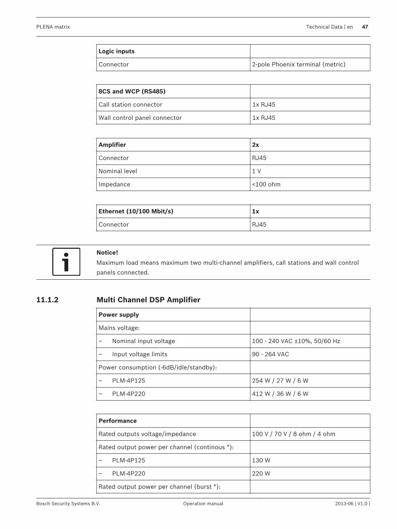
Logic inputs
Connector 2‑pole Phoenix terminal (metric)
8CS and WCP (RS485)
Call station connector 1x RJ45
Wall control panel connector 1x RJ45
Amplifier 2x
Connector RJ45
Nominal level 1 V
Impedance <100 ohm
Ethernet (10/100 Mbit/s) 1x
Connector RJ45
Notice!
Maximum load means maximum two multi-channel amplifiers, call stations and wall control
panels connected.
Multi Channel DSP Amplifier
Power supply
Mains voltage:
– Nominal input voltage 100 - 240 VAC ±10%, 50/60 Hz
– Input voltage limits 90 - 264 VAC
Power consumption (-6dB/idle/standby):
– PLM‑4P125 254 W / 27 W / 6 W
– PLM‑4P220 412 W / 36 W / 6 W
Performance
Rated outputs voltage/impedance 100 V / 70 V / 8 ohm / 4 ohm
Rated output power per channel (continous *):
– PLM‑4P125 130 W
– PLM‑4P220 220 W
Rated output power per channel (burst *):
11.1.2
PLENA matrix Technical Data | en 47
Bosch Security Systems B.V. Operation manual 2013-06 | V1.0 |

– PLM‑4P125 130 W
– PLM‑4P220 220 W
Bridged (CH 1‑2 / 3‑4) (continous *):
– PLM‑4P125 250 W
– PLM‑4P220 385 W
Bridged (CH 1‑2 / 3‑4) (burst *):
– PLM‑4P125 250 W
– PLM‑4P220 445 W
THD+N (1 kHz, 6 dBFS):
– PLM‑4P125 0.1 %
– PLM‑4P220 0.03 %
Dynamic range (A‑weighted):
– PLM‑4P125 >101 dB
– PLM‑4P220 >102 dB
Frequency response (-1dB) 65 Hz to 20 kHz (+0/‑3 dB)
Crosstalk @ 1 kHz <-70 dB
* According to CEA‑490‑A R‑2008
Connectors
Inputs (wired in parallel): – 4x 3‑pin XLR balanced– 4x 3‑pole balanced Phoenix
terminal (Metric)– 1x RJ45 (Amp Link)
– Loudspeaker output 4x 3‑pole Phoenix terminal (Metric)
– Logic and standby overide 2‑pole Phoenix terminal (Metric)
Ethernet Network 10/100 Mbps RJ45
12 V output power for motion sensor 2‑pole Phoenix terminal (Metric)
48 en | Technical Data PLENA matrix
2013-06 | V1.0 | Operation manual Bosch Security Systems B.V.
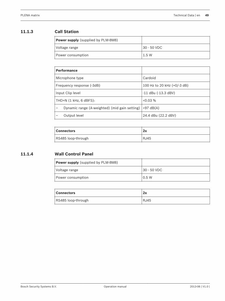
Call Station
Power supply (supplied by PLM‑8M8)
Voltage range 30 - 50 VDC
Power consumption 1.5 W
Performance
Microphone type Cardoid
Frequency response (-3dB) 100 Hz to 20 kHz (+0/‑3 dB)
Input Clip level -11 dBu (-13.3 dBV)
THD+N (1 kHz, 6 dBFS): <0.03 %
– Dynamic range (A‑weighted) (mid gain setting) >97 dB(A)
– Output level 24.4 dBu (22.2 dBV)
Connectors 2x
RS485 loop‑through RJ45
Wall Control Panel
Power supply (supplied by PLM‑8M8)
Voltage range 30 ‑ 50 VDC
Power consumption 0.5 W
Connectors 2x
RS485 loop‑through RJ45
11.1.3
11.1.4
PLENA matrix Technical Data | en 49
Bosch Security Systems B.V. Operation manual 2013-06 | V1.0 |
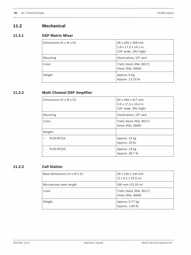
Mechanical
DSP Matrix Mixer
Dimensions (H x W x D) 45 x 440 x 358 mm1.8 x 17.3 x 14.1 in(19" wide, 1RU high)
Mounting Stand-alone, 19" rack
Color Trafic black (RAL 9017)Silver (RAL 9006)
Weight Approx. 6 kgApprox. 13.23 lb
Multi Channel DSP Amplifier
Dimensions (H x W x D) 90 x 440 x 417 mm3.5 x 17.3 x 16.4 in(19" wide, 2RU high)
Mounting Stand-alone, 19" rack
Color Trafic black (RAL 9017)Silver (RAL 9006)
Weight:
– PLM‑4P125 Approx. 15 kgApprox. 33 lb
– PLM‑4P220 Approx. 18 kgApprox. 39.7 lb
Call Station
Base dimensions (H x W x D) 50 x 156 x 140 mm(2 x 6.1 x 25.5 in)
Microphone stem length 390 mm (15.35 In)
Color Trafic black (RAL 9017)Silver (RAL 9006)
Weight Approx. 0.77 kgApprox. 1.69 lb
11.2
11.2.1
11.2.2
11.2.3
50 en | Technical Data PLENA matrix
2013-06 | V1.0 | Operation manual Bosch Security Systems B.V.

Wall Control Panel
Base dimensions (H x W x D) 130 x 100 x 30 mm5.1 x 3.9 x 1.2 in
Mounting Surface mount bracket
Color Trafic black (RAL 9017)Silver (RAL 9006)
Weight Approx. 0.13 kgApprox. 0.29 lb
11.2.4
PLENA matrix Technical Data | en 51
Bosch Security Systems B.V. Operation manual 2013-06 | V1.0 |
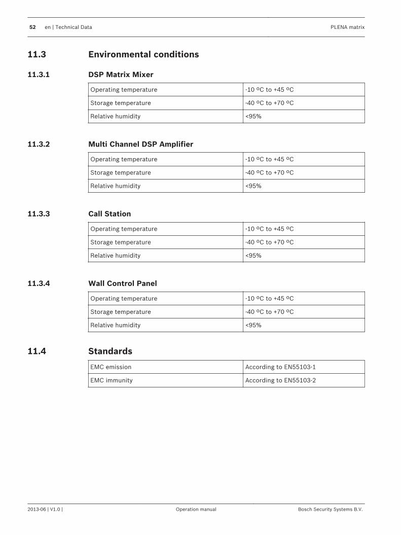
Environmental conditions
DSP Matrix Mixer
Operating temperature -10 ºC to +45 ºC
Storage temperature -40 ºC to +70 ºC
Relative humidity <95%
Multi Channel DSP Amplifier
Operating temperature -10 ºC to +45 ºC
Storage temperature -40 ºC to +70 ºC
Relative humidity <95%
Call Station
Operating temperature -10 ºC to +45 ºC
Storage temperature -40 ºC to +70 ºC
Relative humidity <95%
Wall Control Panel
Operating temperature -10 ºC to +45 ºC
Storage temperature -40 ºC to +70 ºC
Relative humidity <95%
Standards
EMC emission According to EN55103-1
EMC immunity According to EN55103-2
11.3
11.3.1
11.3.2
11.3.3
11.3.4
11.4
52 en | Technical Data PLENA matrix
2013-06 | V1.0 | Operation manual Bosch Security Systems B.V.

Bosch Security Systems B.V.
Torenallee 49
5617 BA Eindhoven
The Netherlands
www.boschsecurity.com
© Bosch Security Systems B.V., 2013