Embed Size (px)
Citation preview

For Pub
lic C
ommen
t
15E011R0 g
STAGE : PUBLIC COMMENT (40.20) DATE : 01/01/2016 - 01/03/2016
Rubber insulated cables of rated voltages up to and including 450 V/750 V - Part 2: Test methods ICS: 29.060 Descriptors: rubber, insulated cable rated voltage, 450 V/750 V, test methods
© Copyright DEPARTMENT OF STANDARDS MALAYSIA
DRAFT MALAYSIAN STANDARD

For Pub
lic C
ommen
t
15E011R0 g
STANDARDS MALAYSIA 2015 - All rights reserved i
Contents
Page Committee representation iii Foreword v 1 Scope 1 2 Normative references 1 3 Definitions 2 4 General requirements 2 5 Electrical tests 5 6 Tests of mechanical strength of completed flexible cables 6 7 Tests for mechanical properties after air oven and air bomb ageing of
insulation consisting of rubber compound IE4 11 8 Flame retardant test for lift cables 11 9 Tests for resistance to heat of textile braids 12
For Pub
lic C
ommen
t
15E011R0 g
ii STANDARDS MALAYSIA 2015 - All rights reserved
Committee representation The Industry Standards Committee on Generation, Transmission and Distribution of Energy (ISC E) under whose authority this Malaysian Standard was developed, comprises representatives from the following organisations: Association of Consulting Engineers Malaysia Atomic Energy Licensing Board Department of Standards Malaysia Federation of Malaysian Manufacturers Jabatan Kerja Raya Malaysia Malaysian Cable Manufacturers Association Malaysian Electrical Appliances and Distributors Association Malaysian Green Technology Corporation Ministry of Domestic Trade, Co-operatives and Consumerism Ministry of International Trade and Industry Persatuan Kontraktor Elektrikal dan Mekanikal Melayu Malaysia SIRIM Berhad (Secretariat) SIRIM QAS International Sdn Bhd Suruhanjaya Komunikasi dan Multimedia Malaysia Suruhanjaya Tenaga Tenaga Nasional Berhad The Electrical and Electronics Association of Malaysia The Institution of Engineers, Malaysia Universiti Malaya Universiti Teknologi Malaysia The Technical Committee on Cables and Cable Accessories which supervised the development of this Malaysian Standard is managed by the Malaysian Cable Manufacturers Association in its capacity as an authorised Standards-Writing Organisation and consists of representatives from the following organisations: Association of Consulting Engineers Malaysia Jabatan Bomba dan Penyelamat Malaysia Jabatan Kerja Raya Malaysia Malaysian Association of Standard Users Malaysian Cable Manufacturers Association (Secretariat) Malaysian Electrical Appliances and Distributors Association Maxis Berhad Petroliam Nasional Berhad SIRIM Berhad SIRIM QAS International Sdn Bhd Suruhanjaya Tenaga Telekom Malaysia Berhad Tenaga Nasional Berhad Universiti Malaya

For Pub
lic C
ommen
t
15E011R0 g
STANDARDS MALAYSIA 2015 - All rights reserved iii
Committee representation (continued) The Working Group on Cables and Cable Accessories which developed this Malaysian Standard consists of representatives from the following organisations: Central Cables Berhad Fajar Cables Sdn Bhd FEC Cables (M) Sdn Bhd Federal Power Sdn Bhd Fujikura Federal Cables Sdn Bhd Leader Cable Industry Berhad Malaysian Cable Manufacturers Association (Secretariat) Master Tec Wire and Cable Sdn Bhd Mega Kabel Sdn Bhd Olympic Cable Company Sdn Bhd Pan-International Wire and Cable Sdn Bhd Power Cables Malaysia Sdn Bhd Sama Kebel Sdn Bhd Sindutch Cable Manufacturer Sdn Bhd Tai Sin Electric Cables (M) Sdn Bhd Tenaga Cable Industries Sdn Bhd Tonn Cable Sdn Bhd Universal Cable (M) Berhad Universal Cable (Sarawak) Sdn Bhd Utama Cables Sdn Bhd

For Pub
lic C
ommen
t
15E011R0 g
iv STANDARDS MALAYSIA 2015 - All rights reserved
Foreword This Malaysian Standard was developed by the Working Group on Cables and Cable Accessories under the authority of the Industry Standards Committee on Generation, Transmission and Distribution of Energy. Development of this standard was carried out by the Malaysian Cable Manufacturers Association which is the Standards-Writing Organisation (SWO) appointed by SIRIM Berhad to develop standards for cables and cable accessories. MS 2127 consists of the following parts, under the general title Rubber insulated cables of rated voltages up to and including 450 V/750 V: Part 1: General requirements Part 2: Test methods Part 3: Heat resistant silicone insulated cables Part 4: Cords and flexible cables Part 5: Lift cables Part 6: Arc welding electrode cables Part 7: Heat resistant ethylene-vinyl-acetate rubber insulated cables Part 8: Cords for applications requiring high flexibility This part of Malaysian Standard cancels and replaces MS 140:1987, Insulated flexible cords and cables, MS 276:1987, Rubber insulation and sheath of electric cables and MS 278:1987, Rubber insulated cables for electric power and lighting. Compliance with a Malaysian Standard does not of itself confer immunity from legal obligations.
For Pub
lic C
ommen
t
15E011R0 g
STANDARDS MALAYSIA 2015 - All rights reserved
Rubber insulated cables of rated voltages up to and including 450 V/750 V - Part 2: Test methods
1 Scope This part of Malaysian Standard applies to the methods of carry out the tests specified on cables with insulation, and sheath if any, based on rubber, of rated voltages up to and including 450/750 V used in appliances of nominal voltages not exceeding 450 V/750 V a.c. The tests are applicable to the types of cables are given in MS 2127: Parts 3, 4, 5 and etc. 2 Normative references The following normative references are indispensable for the application of this standard. For dated references, only the edition cited applies. For undated references, the latest edition of the normative reference (including any amendments) applies. MS 2127: Part 1, Rubber insulated cables of rated voltages up to and including 450 V/750 V - Part 1: General requirements MS 2127: Part 3, Rubber insulated cables of rated voltages up to and including 450 V/750 V - Part 3: Heat resistant silicone insulated cables MS 2127: Part 4, Rubber insulated cables of rated voltages up to and including 450 V/750 V - Part 4: Cords and flexible cables MS 2127: Part 5, Rubber insulated cables of rated voltages up to and including 450 V/750 V - Part 5: Lift cables MS 2127: Part 6, Rubber insulated cables of rated voltages up to and including 450 V/750 V - Part 6: Arc welding electrode cables MS 2127: Part 7, Rubber insulated cables of rated voltages up to and including 450 V/750 V - Part 7: Heat resistant ethylene-vinyl acetate rubber insulated cables MS 2127: Part 8 Rubber insulated cables of rated voltages up to and including 450 V/750 V - Part 8: Cords for applications requiring high flexibility MS IEC 60811-1-1, Common test methods for insulating and sheathing materials of electric cables and optical cables - Part 1-1: Methods for general application - Measurement of thickness and overall dimensions - Tests for determining the mechanical properties MS IEC 60811-1-2, Common test methods for insulating and sheathing materials of electric cables - Part 1: Methods for general application - Section 2: Thermal ageing methods IEC 60332-1-2, Tests on electric and optical fibre cables under fire conditions - Part 1-2: Test for vertical flame propagation for a single insulated wire or cable - procedure for 1 kW pre-mixed flame ISO 1302, Technical drawings - Method of indicating surface texture

For Pub
lic C
ommen
t
15E011R0 g
2 STANDARDS MALAYSIA 2015 - All rights reserved
3 Definitions 3.1 general For the purposes of this standard, the definitions given in MS 2127: Part 1 apply. The tests specified are type tests (symbol T) and/or sample tests (symbol S) as specified in the particular Malaysian Standards (MS 2127: Parts 3 and 4, etc.). 4 General requirements 4.1 Sampling If a marking is marked on the insulation or sheath, samples used for the tests shall be taken so as to include such marking. For multicore cables, except for the test specified in 4.6, not more than three cores (of different colours, if applicable) shall be tested unless otherwise specified. 4.2 Pre-conditioning All the tests shall be carried out not less than 16 h after the extrusion of the insulating materials or sheathing materials. 4.3 Test temperature Unless otherwise specified, tests shall be made at ambient temperature. 4.4 Test voltage Unless otherwise specified, the test voltage shall be alternating current 49 Hz to 61 Hz of approximately sine-wave form, the ratio peak value/r.m.s. value being equal to with a tolerance of ± 7 %. The values quoted are r.m.s. values. 4.5 Checking of the durability of colours and markings Compliance with this requirement shall be checked by trying to remove the marking by rubbing lightly ten times with a piece of cotton wool or cloth soaked in water. 4.6 Measurement of insulation thickness The insulation thickness shall be measured in accordance with 8.1 of MS IEC 60811-1-1. One sample of cable shall be taken from each of three places, separated by at least 1 m. Compliance shall be checked on each core of cables having up to five cores, and on any five cores of cables with more than five cores. 4.6.1 Evaluation of results The mean of the 18 values (in millimeters) obtained from the three pieces of insulation from each core shall be calculated to two decimal places and rounded off as given below, and this shall be taken as the mean value of the thickness of insulation.

For Pub
lic C
ommen
t
15E011R0 g
STANDARDS MALAYSIA 2015 - All rights reserved 3
If in the calculation the second decimal figure is 5 or more, the first decimal figure shall be raised to the next number, thus, for example, 1.74 shall be rounded off to 1.7 and 1.75 to 1.8. The lowest of all values obtained shall be taken as the minimum thickness of insulation at any place. 4.7 Measurement of sheath thickness The thickness of sheath shall be measured in accordance with 8.2 of MS IEC 60811-1-1. One sample of cable shall be taken from each of three places, separated by at least 1 m. 4.7.1 Evaluation of results The mean of all the values (in millimeters) obtained from the three pieces of sheath shall be calculated to two decimal places and rounded off as given below, and this shall be taken as the mean value of the thickness of sheath. If in the calculation the second decimal figure is 5 or more, the first decimal figure shall be raised to the next number, thus, for example, 1.74 shall be rounded off to 1.7 and 1.75 to 1.8. The lowest of all values obtained shall be taken as the minimum thickness of insulation at any place. 4.8 Measurement of overall dimensions and ovality The measurement of the overall diameter of any circular cable and of the overall dimensions of flat cables with a major dimension not exceeding 15 mm shall be carried out in accordance with 8.3 of MS IEC 60811-1-1. For the measurement of flat cables with a major dimension exceeding 15 mm, a micrometer, a profile projector or similar appliance shall be used. The mean of the values obtained shall be taken as the mean overall dimension. For checking the cable ovality of circular sheathed cables, two measurements shall be made at the same cross-section of the cable. 4.9 Solderability test for untinned conductors 4.9.1 Aim of the test The test is intended to verify the effectiveness of the separator between the non-tinned conductor and the insulation. Compliance is checked by the solder bath method described below. 4.9.2 Selection of samples and preparation of test pieces One sample having a length suitable for the bending test defined below is taken at three points in the cable, and the cores in each sample are carefully separated from all other components.

For Pub
lic C
ommen
t
15E011R0 g
4 STANDARDS MALAYSIA 2015 - All rights reserved
Each sample of core thus obtained is wound, in three turns, on a mandrel, the diameter of which is three times that of the core. The sample is then unwound and straightened out, whereupon it is wound again in such a way that the fibre which was compressed in the first case becomes the stretched fibre in the second. This cycle of operations is repeated two more times, which represents three bending operations in one direction and three in the other. From each sample of core which has been straightened out after the third cycle of bending operations, a test piece having a length of about 15 cm is taken from that part of the core which has actually been wound. Each test piece is then subjected to accelerated ageing in a hot-air oven for 240 h at a temperature of (70 ± 1) C. After this accelerated ageing, the test pieces are left at ambient temperature for at least 16 h. Then each test piece is striped at one end over a length of 60 mm and is subjected to the solderability test by the solder-bath method described below. 4.9.3 Description of the solder bath The solder bath shall have a volume sufficient to ensure that the temperature of the solder remains uniform at the moment when the conductor is introduced. It shall be provided with a device which maintains the temperature of the solder at (270 ± 10) C. The height of the solder bath shall be at least 75 mm. The visible surface area of the bath shall be reduced as far as possible, by using a perforated plate of heat resisting material in order to protect the core against direct radiation from the bath. The composition of the solder shall be tin (between 59.5 % and 61.5 %) and lead. Impurities (as a percentage of the total mass) shall not exceed the values stated in Table 1. 4.9.4 Test procedure The surface of the solder bath shall be kept clean and shining. After immersion for 10 s at ambient temperature in a pickling bath constituted by a solution of zinc chloride in water (ZnCl being 10 % of the total mass), the bared end of each test piece shall be immersed in the solder bath over a length of 50 mm in the direction of its longitudinal axis. The speed of immersion is (25 ± 5) mm/s. The duration of immersion is (5 ± 0.5) s. The speed of emergence is (25 ± 5) mm/s. An interval lasting 10 s is observed from the start of one immersion to the start of a subsequent immersion. The number of immersions shall be 3. 4.9.5 Requirement The part of the conductor that has been immersed shall be adequately tinned.

For Pub
lic C
ommen
t
15E011R0 g
STANDARDS MALAYSIA 2015 - All rights reserved 5
5 Electrical tests 5.1 Electrical resistance of conductors In order to check the electrical resistance of conductors, the resistance of each conductor shall be measured. If necessary, a correction to 20 C and to a length of 1 km shall be obtained by the formula:
R20 = Rt 254.5 x 1 000
(234.5 + t) x L
where t is the temperature of the sample of measurement, expressed in degrees Celsius
(C); R20 is the resistance at 20 C, expressed in ohm/kilometer (/km); Rt is the resistance of L meters of cable at t C, expressed in ohms (); and L is the length of the sample of cable, expressed in meters (length of the complete
cable and not of the individual cores or wires). The cords need to be left in a test area, which is at reasonably constant temperature for sufficient time to ensure that the cord temperature is equal to the ambient temperature, before measuring the dc resistance of the conductor at room temperature. 5.2 Voltage test carried out on completed cables A sample of cable shall be immersed in water if the cable has no metallic layer. The length of the sample, the temperature of the water and the duration of immersion are given in Table 3 of MS 2127: Part 1. A voltage shall be applied in turn between each conductor and all the others connected together to the water and the metal central heart, if any; and then between all conductors together and the water connected to the metal central heart, if any. The voltage and the duration of its application are given in Table 3 of MS 2127: Part 1. 5.3 Voltage test on cores The test applies to sheathed or braided cables. The test shall be made on a sample of cable of 5 m length. The sheath or the overall braid and any other covering or filling shall be removed without damaging the cores. The cores shall be immersed in water as specified in Table 3 of MS 2127: Part 1, and a voltage shall be applied between the conductors and the water.
For Pub
lic C
ommen
t
15E011R0 g
6 STANDARDS MALAYSIA 2015 - All rights reserved
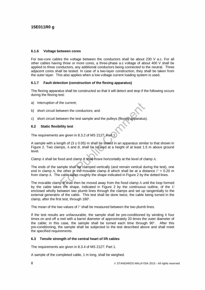
The voltage and the duration of its application are given for each case in Table 3 of MS 2127: Part 1. 5.4 Insulation resistance above 90 C This test method applies to cables or cores with maximum conductor temperatures above 90 C. The test shall be made on the same sample used for the voltage test. A sample of 1.40 m length shall be cut from the cable or core to be tested. In the central part the sample shall be covered with a semi-conducting layer over the length of the screen and over the width of the wire bindings to be applied on these layers. The screen may be a metal braid or a metal tape and shall be applied in such a way as to obtain an active measuring length of 1.0 m. At both ends of the active measuring length, leaving a gap of 1 mm wide, a protective wire binding of approximately 5 mm wide shall be applied on its own semi-conducting layer; any semi-conducting materials covering the gap shall be removed. The sample shall then be wound to a ring with a diameter of approximately 15 D but at least 0.20 m (D is the nominal outer diameter of insulation). The samples shall be maintained in an air oven for at least 2 h at the specified test temperature. The clearance between the sample and the walls of the air oven shall be at least 5 cm. The insulation resistance shall be measured one minute after a voltage between 80 V and 500 V be applied between the conductor and the screen; the protective wire bindings being earthed. This value shall be related to 1 km. None of the resulting values shall be below the minimum insulation resistance value stated in the relevant cable specifications (MS 2127: Part 3, etc.). 6 Tests of mechanical strength of completed flexible cables 6.1 Flexing test 6.1.1 General ` The requirements are given in 8.3.1 of MS 2127: Part 1. This test does not apply to flexible cables with cores of nominal cross-sectional area greater than 4 mm2, nor to cables having more than 18 cores laid up in more than two concentric layers. 6.1.2 Apparatus The following apparatus shall be used in this test method: a) carrier C;
For Pub
lic C
ommen
t
15E011R0 g
STANDARDS MALAYSIA 2015 - All rights reserved 7
b) metal pulleys A and B; and c) restraining clamps D. 6.1.3 Procedure This test shall be carried out by means of the apparatus shown in Figure 1. This apparatus consists of a carrier C, a driving system for the carrier and four pulleys for each sample of cable to be tested. The carrier C supports two pulleys A and B, which are of the same diameter. The two fixed pulleys, at either end of the apparatus, may be of a different diameter from pulleys A and B, but all four pulleys shall be so arranged that the sample is horizontal between them. The carrier makes cycles (forward and backward movements) over a distance of 1 m at an approximately constant speed of 0.33 m/s between each reversal of the direction of movement. The pulleys shall be made of metal and have a semi-circular shaped groove for circular cables and a flat groove for flat cables. The restraining clamps D shall be fixed so that the pull is always applied by the weight from which the carrier is moving away. The distance from one restraining clamp to its support, while the other clamp is resting on its support, shall be of 5 cm maximum. The driving system shall be such that the carrier turns smoothly and without jerks when it reverses from one direction to another. 6.1.4 Sample preparation A sample of flexible cable about 5 m long shall be stretched over the pulleys, as shown in Figure 1, each end being loaded with a weight. The mass of this weight and the diameter of pulleys A and B are given in Table 2. 6.1.5 Current loading of cores For the current loading, either a low voltage or a voltage about 230 V/400 V may be used. During the flexing test, the cable sample shall be loaded with the current specified in Table 3 as follows: a) two and three core cables: all cores to be loaded fully; and b) four and five core cables: three cores to be loaded fully or all cores to be loaded according to the following formula: In = I2 √ (3/n) A/mm2 where n is the number of cores; and I2 is the full current according to Table 3. Cables having more than five cores shall not be loaded. On cores which are not loaded, a signal current shall be applied.
For Pub
lic C
ommen
t
15E011R0 g
8 STANDARDS MALAYSIA 2015 - All rights reserved
6.1.6 Voltage between cores For two-core cables the voltage between the conductors shall be about 230 V a.c. For all other cables having three or more cores, a three-phase a.c voltage of about 400 V shall be applied to three conductors, any additional conductors being connected to the neutral. Three adjacent cores shall be tested. In case of a two-layer construction, they shall be taken from the outer layer. This also applies when a low voltage current loading system is used. 6.1.7 Fault detection (construction of the flexing apparatus) The flexing apparatus shall be constructed so that it will detect and stop if the following occurs during the flexing test: a) interruption of the current; b) short circuit between the conductors; and c) short circuit between the test sample and the pulleys (flexing apparatus).
6.2 Static flexibility test The requirements are given in 8.3.2 of MS 2127: Part 1. A sample with a length of (3 ± 0.05) m shall be tested in an apparatus similar to that shown in Figure 2. Two clamps, A and B, shall be located at a height of at least 1.5 m above ground level. Clamp A shall be fixed and clamp B shall move horizontally at the level of clamp A. The ends of the sample shall be clamped vertically (and remain vertical during the test), one end in clamp A, the other in the movable clamp B which shall be at a distance l’ = 0.20 m from clamp A. The cable takes roughly the shape indicated in Figure 2 by the dotted lines. The movable clamp B shall then be moved away from the fixed clamp A until the loop formed by the cable takes the shape, indicated in Figure 2 by the continuous outline, of the U enclosed wholly between two plumb lines through the clamps and set up tangentially to the external generatrix of the cable. This test shall be done twice, the cable being turned in the clamp, after the first test, through 180. The mean of the two values of l’ shall be measured between the two plumb lines. If the test results are unfavourable, the sample shall be pre-conditioned by winding it four times on and off a reel with a barrel diameter of approximately 20 times the outer diameter of the cable; in this case, the sample shall be turned each time through 90. After this pre-conditioning, the sample shall be subjected to the test described above and shall meet the specified requirements. 6.3 Tensile strength of the central heart of lift cables The requirements are given in 8.3.4 of MS 2127: Part 1. A sample of the completed cable, 1 m long, shall be weighed.
For Pub
lic C
ommen
t
15E011R0 g
STANDARDS MALAYSIA 2015 - All rights reserved 9
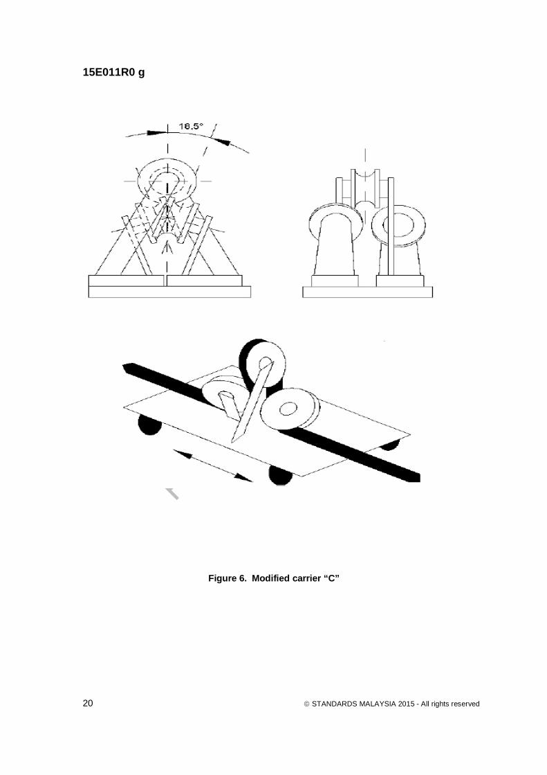
After removal of all covering and cores over a distance of 0.20 m at both ends of the sample, the central heart including the strain-bearing centre shall be subjected to a tensile force corresponding to the mass of 300 m of cable. The force shall be applied for 1 min. A freely hanging weight or a suitable mechanical strength testing machine capable of applying a constant force may be used. 6.4 Wear resistance test The requirements are given in 8.3.3 of MS 2127: Part 1. The test shall be made on three pairs of flexible cable, each sample having a length of about 1 m. In each pair one sample shall be wound so as to give two turns on a fixed reel having a diameter of 40 mm at the bottom of the groove as shown in Figure 3, the distance between the flanges of the reel being such that the turns are in close contact with each other. The sample shall then be fixed to prevent any movement relative to the reel. The other sample shall be placed in the groove formed by the turns and a weight having a mass of 500 g shall be attached to one end. The other end shall be moved up and down over a distance of 0.10 m, at a rate of about 40 single strokes per minute. 6.5 Three pulley flexing test The test shall be carried out in accordance with 6.1 except for the following modifications to the apparatus described hereafter. a) Carrier The apparatus described in 6.1 shall have a modified carrier C, as shown in Figure 6. b) Pulley wheels The three pulley wheels of modified carrier C shall be of equal diameter in accordance with Table 4. c) Speed of carrier The constant speed of the modified carrier C shall be approximately 0.1 m/s. d) Weight The weight applied to stress the conductor as described in 6.1 shall be calculated on the basis of 28 N/mm2 of the conductor cross-section. 6.5.1 Requirements During the test with 1 000 cycles, i.e. 2 000 single movements, neither interruption of the current, nor short-circuit between the conductors, nor short circuit between the cable and the pulleys (the flexing apparatus) shall occur.

For Pub
lic C
ommen
t
15E011R0 g
10 STANDARDS MALAYSIA 2015 - All rights reserved
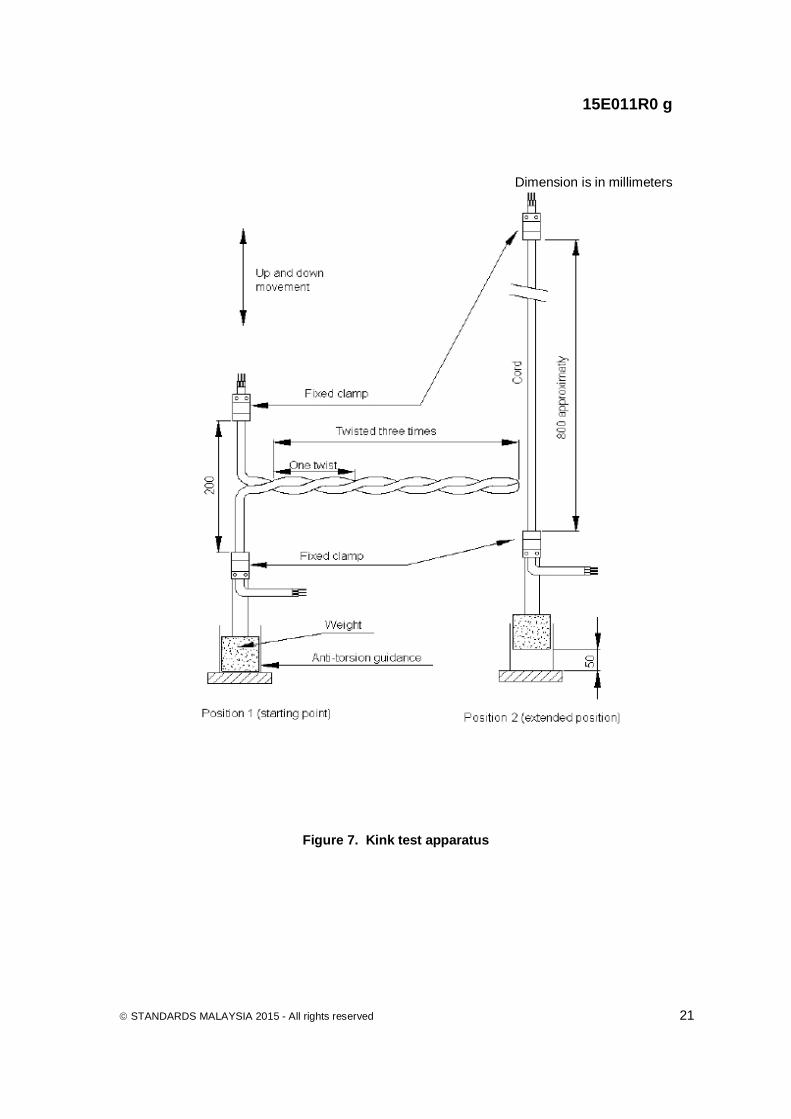
After the required number of cycles the sheath of the cable shall be removed. The cores shall then withstand the voltage test carried out in accordance with 5.3 at a voltage specified in MS 2127: Part 8. 6.6 Kink test 6.6.1 Applicability The test is applicable to two and three core sheathed cords, with a conductor cross-sectional area up to and including 1.5 mm2. 6.6.2 Apparatus The test shall be carried out by means of a tensile strength testing machine or equivalent apparatus. There shall be two clamps for fixing the cord. The upper clamp shall be capable of upwards and downwards movement. The lower clamp shall allow free movement in the vertical direction, but shall be prevented from twisting about its vertical axis so that no change to the torsion in the cord is introduced during the test. The arrangement is shown in Figure 7. 6.6.3 Sample The test cord sample shall have a length of approximately 1 m. The cord shall be twisted three times as shown in position 1 (starting position only) of Figure 7, and then fixed in the upper and lower clamps so that the starting distance between the clamps is 200 mm. The total extended length of cord between the two clamps is approximately 800 mm, as shown in position 2 (extended position) of Figure 7. Four samples shall be prepared for testing, two with the twists applied clockwise and two anti-clockwise. 6.6.4 Test procedure The lower clamp shall be loaded with a weight sufficient to exert the tensile force given in Table 5. Each conductor of the cord shall be loaded with current, as specified in Table 6. The current may be at a low voltage. The movable upper clamp shall make upwards and downwards movements at the rate of nine complete cycles per minute (one complete cycle equals one upwards and downwards movement). The distance of travel for each movement (up or down) shall be 650 mm. When the upper clamp is fully raised, the weight attached to the bottom clamp shall have been raised by about 50 mm (see Figure 7, position 2). A total of 3 000 cycles shall be made on each sample. 6.6.5 Requirements During the test neither interruption of the current nor short circuit between conductors shall occur. Also there shall be no damage (cracking or tearing) to the sheath or any outer covering (textile braid). Textile braids shall have no gap bigger than 2 mm.

For Pub
lic C
ommen
t
15E011R0 g
STANDARDS MALAYSIA 2015 - All rights reserved 11
At the conclusion of the test the sheath and any outer covering shall be removed, and the cores shall be subjected to the voltage test in accordance with 5.3 and at a voltage as specified in MS 2127: Part 8. 7 Tests for mechanical properties after air oven and air bomb ageing of
insulation consisting of rubber compound IE4 7.1 General The tests shall be carried out in accordance with 9.1 of MS IEC 60811-1-1 and 8.1 and 8.3 of MS IEC 60811-1-2 in conjunction with the modifications and additions given hereafter. Test conditions and tests requirements are given in Table 1 of MS 2127: Part 1. 7.2 Sampling and preparation One sample of each core to be tested being of sufficient length shall be taken to provide a minimum of five test pieces for the tensile test after each of the required ageing treatments. 7.3 Ageing procedure The ageing of the pieces of core with the conductor in place shall be carried out as described for tubular and dumb-bell test pieces in 8.1.3.2 and 8.3 of MS IEC 60811-1-2. In cases where it is to be expected that the conductor and the separator, if any, cannot be removed after the relevant ageing treatment without damaging the insulation, it is permitted to remove 30 % of the wires forming the conductor before the ageing treatment. 7.4 Preparation of test pieces and tensile test As soon as the ageing period is completed, the samples shall be removed from the oven or bomb and left at ambient temperature, avoiding direct sunlight for at least 16 h. Test pieces shall be prepared in accordance with 9.1 of MS IEC 60811-1-1. For the preparation of dumb-bell test pieces the side of the insulation which was facing the conductor shall be cut or ground in such a way that the material removed on that side shall be the minimum compatible with adequate smoothing. After this preparation, test pieces shall be subjected to the determination of the cross-sectional area, the conditioning and tensile test procedure in accordance with 9.1 of MS IEC 60811-1-1. 8 Flame retardant test for lift cables The requirements are given in 8.4 of MS 2127-Part 1. The test shall be carried out in accordance with IEC 60332-1-2. Before the test, alternate conductors of the cable shall be connected in series. A voltage of about 220 V in series with a lamp of about 100 W/220 V shall be applied to the two circuits so formed. At the other end of the two circuits, an indicator lamp of about 10 W/220 V shall be connected.

For Pub
lic C
ommen
t
15E011R0 g
12 STANDARDS MALAYSIA 2015 - All rights reserved
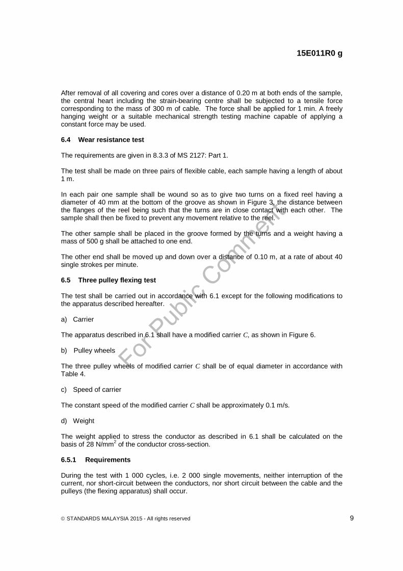
NOTE. For cables with more than one layer of cores, the connection in series of alternate conductors shall be made throughout each layer in turn, so that adjacent cores in each layer are, so far as possible, not in the same circuit. During the test, the indicator lamp shall remain alight. A typical electrical circuit diagram is shown in Figure 4. 9 Tests for resistance to heat of textile braids 9.1 General This test applies to braided cables in MS 2127: Part 8. This test is designed to show that the textile braid has adequate resistance to heat. 9.2 Apparatus a) electrically heated cabinet with natural air flow; b) a block made of aluminium according to Figure 5, with smooth, flat surfaces. Surface
finish in accordance with ISO 1302; roughness class Ra 50; mass of test piece is (1 000 ± 50) g;
c) steel base plate and upright, with guide rods, according to Figure 5, so designed that the
aluminium block can slide between the guide rods without impediment and that any lateral tilting is avoided; and
d) timer, for example, stop-watch. 9.3 Sample The test sample shall be a length of complete cord, approximately 300 mm long. 9.4 Preparation The test sample shall be straightened and arranged in the middle of the aluminium block and as closely as possible to the mean longitudinal axis of the steel base plate as shown in Figure 5, so that one end of the sample protrudes approximately 100 mm from the rear lead-in hole. The aluminium block, in accordance with 9.2 b) shall then be kept in the heating chamber described in 9.2 a), at a temperature of (260 ± 5) C for at least 4 h. 9.5 Test procedure Take the aluminium block out of the cabinet and immediately place it on the sample for
s. Subsequently, the aluminium block shall be removed from the sample. 9.6 Requirement The requirements are given in 8.5 of MS 2127: Part 1.

For Pub
lic C
ommen
t
15E011R0 g
STANDARDS MALAYSIA 2015 - All rights reserved 13
Table 1. Percentage of impurities
Impurities Value (%)
Antimony 0.50 Bismuth 0.25 Copper 0.08
Iron 0.02 Zinc 0.005
Aluminium 0.005 Others 0.080
Table 2. Mass of weight and diameter of pulleys
Types of flexible cables Number
of cores
Nominal cross-sectional area
(mm2)
Mass of
weight (kg)
Diameter of
pulleys1) (mm)
Braided cord 2 or 3 0.75 1 1.5
1.0 1.0 1.0
80 80 80
Ordinary, tough rubber sheathed cord and flexible cable Ordinary polychloroprene or other equivalent synthetic elastomer sheathed cord and flexible cable Heavy polychloroprene or other equivalent synthetic rubber sheathed flexible cable
2 up to 5 0.75 1.0 80 2
1 1.5 2.5 4
1.0 1.0 1.5 2.5
120 120 120 160
3
1 1.5 2.5 4
1.0 1.5 2.0 3.0
120 120 160 160
4
1 1.5 2.5 4
1.5 1.5 2.5 3.5
120 120 160 200
5
1 1.5 2.5 4
1.5 2.5 3.0 4.0
120 160 160 200
7
1.5 2.5
3.5 5.0
160 200
12
1.5 2.5
5.0 7.5
200 200
18
1.5 2.5
7.5 9.0
200 200
1) Diameter measured at the lowest point of the groove.

For Pub
lic C
ommen
t
15E011R0 g
14 STANDARDS MALAYSIA 2015 - All rights reserved
Table 3. Current loadings
Nominal cross-sectional area of conductors
Current (A)
(mm2 ) 0.75 6
1 10 1.5 14 2.5 20 4 25
Table 4. Diameter of pulley wheels
Table 5. Tensile force exerted by the weight
Nominal cross-sectional
area of conductor Tensile force exerted by the weight for cords
Two cores Three cores (mm2) (N) (N) 0.75 30 50
1 50 70 1.5 70 100
Table 6 . Test currents
Nominal cross sectional area of
conductor Test current
(A) (mm2 )
0.75 6 1 10
1.5 16
Cable type (number and nominal cross-sectional
area of conductors)
Diameter of pulley wheels (mm)
(No. x mm2)
2 x 0.75 40 2 x 1 40
3 x 0.75 40 2 x 1.5 45 3 x 1 45
3 x 1.5 50
For Pub
lic C
ommen
t
15E011R0 g
STANDARDS MALAYSIA 2015 - All rights reserved 15
Figure 1. Flexing apparatus Key A metal pulley B metal pulley C carrier D restraining clamps

For Pub
lic C
ommen
t
15E011R0 g
16 STANDARDS MALAYSIA 2015 - All rights reserved
Figure 2. Static flexibility test
Key A clamp B clamp
1.50 m
l = 0.20 m
l’
A B B’
1.50 m
X’ X

For Pub
lic C
ommen
t
15E011R0 g
STANDARDS MALAYSIA 2015 - All rights reserved 17
Dimension is in millimeters
Key a test piece moving in the space between the turns of the fixed test piece b fixed test piece c fixed pulley d weight e distance set to two times measured diameter of sample.
Figure 3. Arrangement for wear resistance test

For Pub
lic C
ommen
t
15E011R0 g
18 STANDARDS MALAYSIA 2015 - All rights reserved
Figure 4. Electric wiring for the flame retardant test
For Pub
lic C
ommen
t
15E011R0 g
STANDARDS MALAYSIA 2015 - All rights reserved 19
Dimension is in millimeters
Figure 5. Assembled test apparatus
For Pub
lic C
ommen
t
15E011R0 g
20 STANDARDS MALAYSIA 2015 - All rights reserved
Figure 6. Modified carrier “C”
For Pub
lic C
ommen
t
15E011R0 g
STANDARDS MALAYSIA 2015 - All rights reserved 21
Dimension is in millimeters
Figure 7. Kink test apparatus
For Pub
lic C
ommen
t
STANDARDS MALAYSIA 2015 - All rights reserved
Acknowledgements Members of Technical Committee on Cables and Cable Accessories Mr Lokman Ahmad Dahlan (Chairman) Malaysian Cable Manufacturers Association Ms Sara Kong (Secretary) Malaysian Cable Manufacturers Association Ir Looi Hip Peu Association of Consulting Engineers
Malaysia Mr Ahmad Isram Osman Jabatan Bomba dan Penyelamat Malaysia Ir Hj Mohd Fazli Osman Jabatan Kerja Raya Malaysia Ms Anuradha Chelliah Malaysian Association of Standard Users Mr V. T. Doshi Malaysian Electrical Appliances and
Distributors Association Mr Vimalan Jeyaseelan Maxis Berhad Mr M. Faudzi M. Yasir Petroliam Nasional Berhad Ms Marina Mahdar SIRIM Berhad Mr Mohamad Nazif Zakaria/ SIRIM QAS International Sdn Bhd Ms Roslinah Abdullah Ir Amir Hassan Suruhanjaya Tenaga Mr Mohamad Anuar Nordin/Ms Norizan Melan Telekom Malaysia Berhad Mr Ahmad Fared Osman/ Mr Najib Fadhil Mohd Bisri Mr Toh Kim Beng Tenaga Nasional Berhad Dr Mohd Rozailan Ibrahim Universiti Malaya Members of Working Group on Cables and Cable Accessories Mr Lokman Ahmad Dahlan (Chairman) Power Cables Malaysia Sdn Bhd Ms Sara Kong (Secretary) Malaysian Cable Manufacturers Association Mr Ahmad Riduan Central Cables Sdn Bhd Mr Teh Min Chet/Mr Goh Seow Chung Fajar Cables Sdn Bhd Mr TH Vong/Mr Amizar Hashim FEC Cables (M) Sdn Bhd Mr Mohd Nasir Hashim/Mr Marzuki Mustapha Federal Power Sdn Bhd Ms Cheng Siew Guay Fujikura Federal Cables Sdn Bhd Mr Tan Lip Keat/Mr Shmeni Shariff Leader Cable Industry Berhad Mr Yong Tat Soon Olympic Cable Company Sdn Bhd Mr Low Yoon Onn Sindutch Cable Manufacturer Sdn Bhd Mr Ng Hien Shui Tai Sin Electric Cables (M) Sdn Bhd Ms Nor Hanita Abdul Ghani/ Tenaga Cable Industries Sdn Bhd Ms Zati Izazi Muhamad Zaki Mr Lim Cheng Meng Tonn Cable Sdn Bhd Mr Chen Wee Tong/ Ms Raihana Mohd Harith Universal Cable (M) Berhad


![Standard is at Ion for HALAL Food [SIRIM]](https://img.pdfslide.us/doc/110x75/5478d902b379597b2b8b45cc/standard-is-at-ion-for-halal-food-sirim.jpg)