Embed Size (px)
Citation preview
All rights reserved. No part of this document may be stored, copied or transmitted, by any means, without the permission in written of the Legal Owner
© 2016 ALBEDO Telecom
W H I T E PA P E Rp
tpo
w.w
p 0
7/1
6
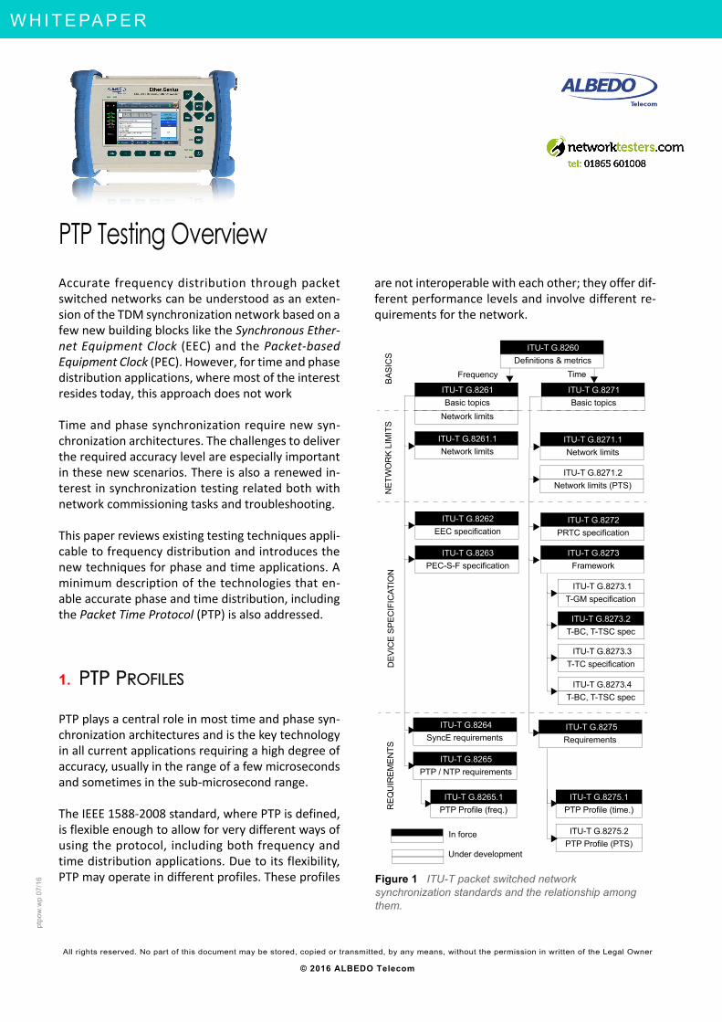
PTP Testing OverviewAccurate frequency distribution through packetswitched networks can be understood as an exten‐sion of the TDM synchronization network based on afew new building blocks like the Synchronous Ether‐net Equipment Clock (EEC) and the Packet‐basedEquipment Clock (PEC). However, for time and phasedistribution applications, where most of the interestresides today, this approach does not work
Time and phase synchronization require new syn‐chronization architectures. The challenges to deliverthe required accuracy level are especially importantin these new scenarios. There is also a renewed in‐terest in synchronization testing related both withnetwork commissioning tasks and troubleshooting.
This paper reviews existing testing techniques appli‐cable to frequency distribution and introduces thenew techniques for phase and time applications. Aminimum description of the technologies that en‐able accurate phase and time distribution, includingthe Packet Time Protocol (PTP) is also addressed.
1. PTP PROFILES
PTP plays a central role in most time and phase syn‐chronization architectures and is the key technologyin all current applications requiring a high degree ofaccuracy, usually in the range of a few microsecondsand sometimes in the sub‐microsecond range.
The IEEE 1588‐2008 standard, where PTP is defined,is flexible enough to allow for very different ways ofusing the protocol, including both frequency andtime distribution applications. Due to its flexibility,PTP may operate in different profiles. These profiles
are not interoperable with each other; they offer dif‐ferent performance levels and involve different re‐quirements for the network.
ITU-T G.8260
Definitions & metrics
ITU-T G.8271
Basic topics
ITU-T G.8261
Basic topics
Network limits
ITU-T G.8261.1
Network limits
ITU-T G.8271.1
Network limits
ITU-T G.8262
EEC specification
ITU-T G.8263
PEC-S-F specification
ITU-T G.8272
PRTC specification
IITU-T G.8273.1
T-GM specification
ITU-T G.8273
Framework
ITU-T G.8273.2
T-BC, T-TSC spec
IITU-T G.8273.3
T-TC specification
ITU-T G.8271.2
Network limits (PTS)
IITU-T G.8273.4
T-BC, T-TSC spec
ITU-T G.8264
SyncE requirements
ITU-T G.8265
PTP / NTP requirements
ITU-T G.8275
Requirements
Figure 1 ITU-T packet switched network synchronization standards and the relationship among them.
ITU-T G.8265.1
PTP Profile (freq.)
ITU-T G.8275.1
PTP Profile (time.)
ITU-T G.8275.2
PTP Profile (PTS)In force
Under development
BA
SIC
SN
ET
WO
RK
LIM
ITS
Frequency Time
DE
VIC
E S
PE
CIF
ICA
TIO
NR
EQ
UIR
EM
EN
TS
Network ing & Telecoms - P T P T e s t i n g O v e r v i e w 2 / 24
A L
B E
D O
- W
H I
T E
P A
P E
R
AL B
ED
O T
ele
com
- R
eg
iste
r ed
in B
arc
elo
na
, B
oo
k 41
61
3, P
age
15
5,
Sh
ee
t B-3
9 08
86
- V
AT
: E
SB
652
30
2 2
Pr o f es s i ona l Te l eco m S o l u t io ns
TEST- LABOS - TAPS - WAN EMULATION - E1 - GBE - SYNCE - WLESS - LTE - 3G - IPTV - VoIP - QoS - SLA - ONEWAY - DATACOM - POLQA - PTP - JITTER - WANDER
As stated in IEEE 1588‐2008, the purpose of a PTPprofile is to allow organizations to define specificselections of attribute values and optional featuresof PTP that, when using the same transport proto‐col, inter‐work and achieve a performance thatmeets the requirements of a particular application.
Typical profile examples are the Default profiles de‐fined in IEEE 1588‐2008 (two basic general purposeprofiles), the Power Profile (IEEE C37.238‐2011),the Enterprise profile (currently an IETF draft) andthe Telecom profiles (ITU‐T G.8265.1, G.8275.1 andG.8275.2). Discussion about the PTP Telecom pro‐files together with the Default profiles are the mainsubject of this paper.
The ITU-T G.8265.1 Frequency Profile
The aim of the ITU‐T G.8275.1 PTP profile for fre‐quency synchronization is to adapt PTP to the com‐mon telecom network synchronization practices.The purpose of this profile is not to provide betterperformance than any previous protocol or to de‐fine new functionality in the synchronization net‐
work but to extend the existing network to includePTP as a protocol suitable to carry synchronizationwith a minimum impact in the installed infrastruc‐ture based on TDM technology (or SynchronousEthernet).
One interesting feature of the ITU‐T G.8265.1 pro‐file is the ability to operate in one‐way mode. PTPmasters use the Sync message flow to share timestamps with their peers (slave clocks, boundaryclocks). If time synchronization between the mas‐ter and its peers is required, then the time it takesfor the remote end to receive the time stamp has tobe compensated for in some way. This is donethrough either the end‐to‐end or peer‐to‐peer pathdelay mechanisms. If no time synchronization is re‐quired, there is no need to apply any delay com‐pensation and the message flows associated to thepath delay mechanism could be removed. Thisone‐way operation mode is allowed by IEEE1588‐2008 and it is optional within ITU‐T G.8265.1.
PTP operation has to be compatible with existingtelecommunication networks which may not in‐clude specific support for PTP. Actually, it is as‐sumed that the network may be completelyunaware of PTP. This requirement restricts the waythe protocol has to be deployed in several aspects:
• UDP over IPv4 (IEEE 1588‐2008, Annex D) is thechosen transport protocol rather than Ethernetor other protocols. This is because of the uni‐versal availability of IPv4.
• Unicast is the only allowed transmission mech‐anism. Multicast may be more efficient but pro‐visioning multicast is also more complex and itmay not be available, or even if it is availablethe network administrator may decide to re‐strict its use for security reasons. In ITU‐TG.8265.1 networks, PTP slaves must requestpermission from the master to exchange PTPmessages through the signaling mechanism de‐fined by IEEE 1588‐2008 and complemented byITU‐T G.8265.1.
• No on‐path support through boundary or trans‐parent clocks is used. Actually, PTP masters(PEC‐M) and slaves (PEC‐S) are the only PTP en‐tities considered by ITU‐T G.8265.1 profile. Tocompensate for the lack of support from thenetwork, the ITU‐T G.8265.1 standard allowsfor message rates higher than in other profiles
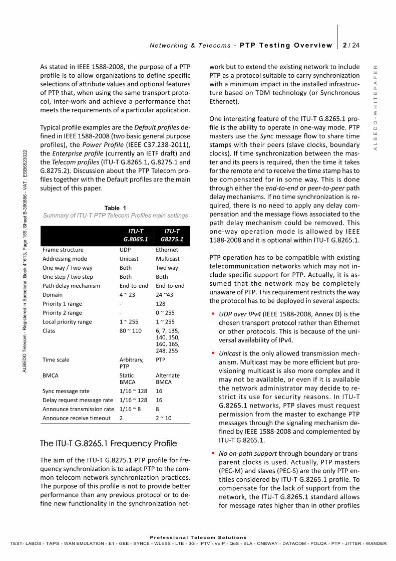
Table 1Summary of ITU-T PTP Telecom Profiles main settings
ITU‐T G.8065.1
ITU‐T G8275.1
Frame structure UDP Ethernet
Addressing mode Unicast Multicast
One way / Two way Both Two way
One step / two step Both Both
Path delay mechanism End‐to‐end End‐to‐end
Domain 4 ~ 23 24 ~43
Priority 1 range ‐ 128
Priority 2 range ‐ 0 ~ 255
Local priority range 1 ~ 255 1 ~ 255
Class 80 ~ 110 6, 7, 135, 140, 150, 160, 165, 248, 255
Time scale Arbitrary, PTP
PTP
BMCA StaticBMCA
Alternate BMCA
Sync message rate 1/16 ~ 128 16
Delay request message rate 1/16 ~ 128 16
Announce transmission rate 1/16 ~ 8 8
Announce receive timeout 2 2 ~ 10
Network ing & Telecoms - P T P T e s t i n g O v e r v i e w 3 / 24
A L
B E
D O
- W
H I
T E
P A
P E
R
AL B
ED
O T
ele
com
- R
eg
iste
r ed
in B
arc
elo
na
, B
oo
k 41
61
3, P
age
15
5,
Sh
ee
t B-3
9 08
86
- V
AT
: E
SB
652
30
2 2
Pr o f es s i ona l Te l eco m S o l u t io ns
TEST- LABOS - TAPS - WAN EMULATION - E1 - GBE - SYNCE - WLESS - LTE - 3G - IPTV - VoIP - QoS - SLA - ONEWAY - DATACOM - POLQA - PTP - JITTER - WANDER
(up to 128 messages/s for Sync and Delay re‐quest messages). Another consequence of thelack of on‐path support is that the path delaymechanism cannot be peer‐to‐peer and there‐fore if a path delay mechanism is used it has tobe end‐to‐end.
One of ITU‐T G.8261 most important requirementsis the need for smooth inter‐operation with existingsynchronization networks. Some features added forthis purpose are:
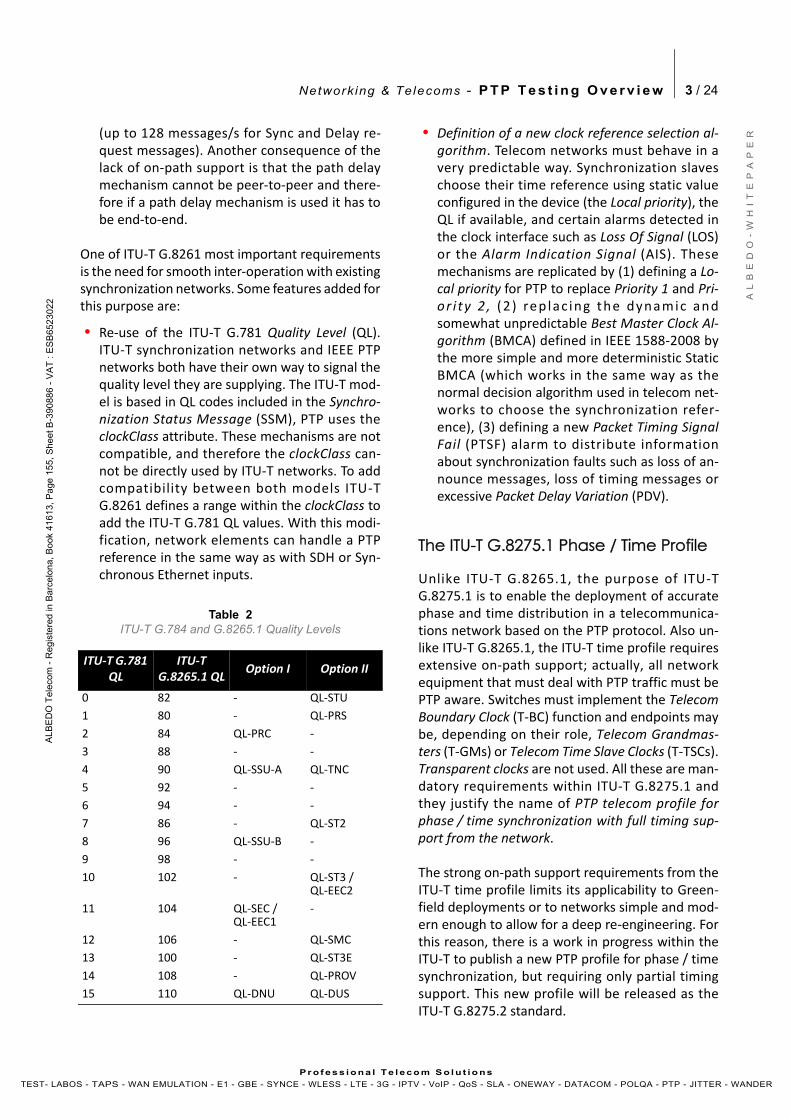
• Re‐use of the ITU‐T G.781 Quality Level (QL).ITU‐T synchronization networks and IEEE PTPnetworks both have their own way to signal thequality level they are supplying. The ITU‐T mod‐el is based in QL codes included in the Synchro‐nization Status Message (SSM), PTP uses theclockClass attribute. These mechanisms are notcompatible, and therefore the clockClass can‐not be directly used by ITU‐T networks. To addcompatibility between both models ITU‐TG.8261 defines a range within the clockClass toadd the ITU‐T G.781 QL values. With this modi‐fication, network elements can handle a PTPreference in the same way as with SDH or Syn‐chronous Ethernet inputs.
• Definition of a new clock reference selection al‐gorithm. Telecom networks must behave in avery predictable way. Synchronization slaveschoose their time reference using static valueconfigured in the device (the Local priority), theQL if available, and certain alarms detected inthe clock interface such as Loss Of Signal (LOS)or the Alarm Indication Signal (AIS). Thesemechanisms are replicated by (1) defining a Lo‐cal priority for PTP to replace Priority 1 and Pri‐or i ty 2 , (2 ) rep lac ing the dynamic andsomewhat unpredictable Best Master Clock Al‐gorithm (BMCA) defined in IEEE 1588‐2008 bythe more simple and more deterministic StaticBMCA (which works in the same way as thenormal decision algorithm used in telecom net‐works to choose the synchronization refer‐ence), (3) defining a new Packet Timing SignalFail (PTSF) alarm to distribute informationabout synchronization faults such as loss of an‐nounce messages, loss of timing messages orexcessive Packet Delay Variation (PDV).
The ITU-T G.8275.1 Phase / Time Profile
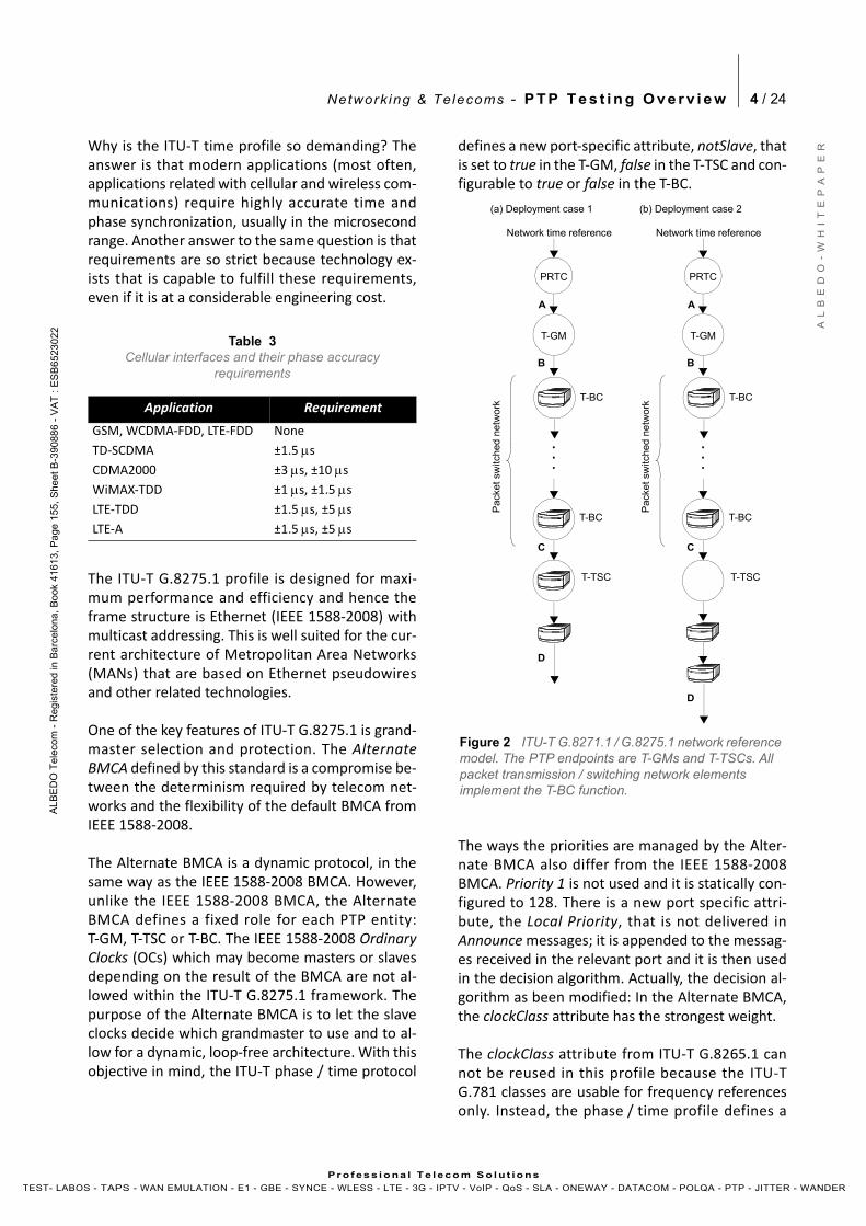
Unlike ITU‐T G.8265.1, the purpose of ITU‐TG.8275.1 is to enable the deployment of accuratephase and time distribution in a telecommunica‐tions network based on the PTP protocol. Also un‐like ITU‐T G.8265.1, the ITU‐T time profile requiresextensive on‐path support; actually, all networkequipment that must deal with PTP traffic must bePTP aware. Switches must implement the TelecomBoundary Clock (T‐BC) function and endpoints maybe, depending on their role, Telecom Grandmas‐ters (T‐GMs) or Telecom Time Slave Clocks (T‐TSCs).Transparent clocks are not used. All these are man‐datory requirements within ITU‐T G.8275.1 andthey justify the name of PTP telecom profile forphase / time synchronization with full timing sup‐port from the network.
The strong on‐path support requirements from theITU‐T time profile limits its applicability to Green‐field deployments or to networks simple and mod‐ern enough to allow for a deep re‐engineering. Forthis reason, there is a work in progress within theITU‐T to publish a new PTP profile for phase / timesynchronization, but requiring only partial timingsupport. This new profile will be released as theITU‐T G.8275.2 standard.
Table 2ITU-T G.784 and G.8265.1 Quality Levels
ITU‐T G.781 QL
ITU‐T G.8265.1 QL
Option I Option II
0 82 ‐ QL‐STU
1 80 ‐ QL‐PRS
2 84 QL‐PRC ‐
3 88 ‐ ‐
4 90 QL‐SSU‐A QL‐TNC
5 92 ‐ ‐
6 94 ‐ ‐
7 86 ‐ QL‐ST2
8 96 QL‐SSU‐B ‐
9 98 ‐ ‐
10 102 ‐ QL‐ST3 / QL‐EEC2
11 104 QL‐SEC / QL‐EEC1
‐
12 106 ‐ QL‐SMC
13 100 ‐ QL‐ST3E
14 108 ‐ QL‐PROV
15 110 QL‐DNU QL‐DUS
Network ing & Telecoms - P T P T e s t i n g O v e r v i e w 4 / 24
A L
B E
D O
- W
H I
T E
P A
P E
R
AL B
ED
O T
ele
com
- R
eg
iste
r ed
in B
arc
elo
na
, B
oo
k 41
61
3, P
age
15
5,
Sh
ee
t B-3
9 08
86
- V
AT
: E
SB
652
30
2 2
Pr o f es s i ona l Te l eco m S o l u t io ns
TEST- LABOS - TAPS - WAN EMULATION - E1 - GBE - SYNCE - WLESS - LTE - 3G - IPTV - VoIP - QoS - SLA - ONEWAY - DATACOM - POLQA - PTP - JITTER - WANDER
Why is the ITU‐T time profile so demanding? Theanswer is that modern applications (most often,applications related with cellular and wireless com‐munications) require highly accurate time andphase synchronization, usually in the microsecondrange. Another answer to the same question is thatrequirements are so strict because technology ex‐ists that is capable to fulfill these requirements,even if it is at a considerable engineering cost.
The ITU‐T G.8275.1 profile is designed for maxi‐mum performance and efficiency and hence theframe structure is Ethernet (IEEE 1588‐2008) withmulticast addressing. This is well suited for the cur‐rent architecture of Metropolitan Area Networks(MANs) that are based on Ethernet pseudowiresand other related technologies.
One of the key features of ITU‐T G.8275.1 is grand‐master selection and protection. The AlternateBMCA defined by this standard is a compromise be‐tween the determinism required by telecom net‐works and the flexibility of the default BMCA fromIEEE 1588‐2008.
The Alternate BMCA is a dynamic protocol, in thesame way as the IEEE 1588‐2008 BMCA. However,unlike the IEEE 1588‐2008 BMCA, the AlternateBMCA defines a fixed role for each PTP entity:T‐GM, T‐TSC or T‐BC. The IEEE 1588‐2008 OrdinaryClocks (OCs) which may become masters or slavesdepending on the result of the BMCA are not al‐lowed within the ITU‐T G.8275.1 framework. Thepurpose of the Alternate BMCA is to let the slaveclocks decide which grandmaster to use and to al‐low for a dynamic, loop‐free architecture. With thisobjective in mind, the ITU‐T phase / time protocol
defines a new port‐specific attribute, notSlave, thatis set to true in the T‐GM, false in the T‐TSC and con‐figurable to true or false in the T‐BC.
The ways the priorities are managed by the Alter‐nate BMCA also differ from the IEEE 1588‐2008BMCA. Priority 1 is not used and it is statically con‐figured to 128. There is a new port specific attri‐bute, the Local Priority, that is not delivered inAnnounce messages; it is appended to the messag‐es received in the relevant port and it is then usedin the decision algorithm. Actually, the decision al‐gorithm as been modified: In the Alternate BMCA,the clockClass attribute has the strongest weight.
The clockClass attribute from ITU‐T G.8265.1 cannot be reused in this profile because the ITU‐TG.781 classes are usable for frequency referencesonly. Instead, the phase / time profile defines a
Table 3Cellular interfaces and their phase accuracy
requirements
Application Requirement
GSM, WCDMA‐FDD, LTE‐FDD None
TD‐SCDMA ±1.5 s
CDMA2000 ±3 s, ±10 s
WiMAX‐TDD ±1 s, ±1.5 s
LTE‐TDD ±1.5 s, ±5 s
LTE‐A ±1.5 s, ±5 s
T-BC
PRTC
T-GM
Network time reference
A
B
D
Figure 2 ITU-T G.8271.1 / G.8275.1 network reference model. The PTP endpoints are T-GMs and T-TSCs. All packet transmission / switching network elements implement the T-BC function.
(a) Deployment case 1
T-BC
C
T-TSC
Pack
et sw
itched
netw
ork
T-BC
PRTC
T-GM
Network time reference
A
B
D
(b) Deployment case 2
T-BC
C
T-TSC
Pack
et sw
itched
netw
ork
Network ing & Telecoms - P T P T e s t i n g O v e r v i e w 5 / 24
A L
B E
D O
- W
H I
T E
P A
P E
R
AL B
ED
O T
ele
com
- R
eg
iste
r ed
in B
arc
elo
na
, B
oo
k 41
61
3, P
age
15
5,
Sh
ee
t B-3
9 08
86
- V
AT
: E
SB
652
30
2 2
Pr o f es s i ona l Te l eco m S o l u t io ns
TEST- LABOS - TAPS - WAN EMULATION - E1 - GBE - SYNCE - WLESS - LTE - 3G - IPTV - VoIP - QoS - SLA - ONEWAY - DATACOM - POLQA - PTP - JITTER - WANDER
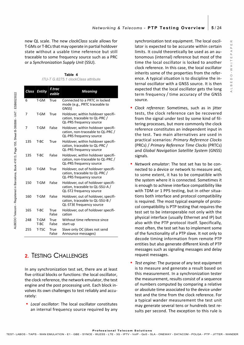
new QL scale. The new clockClass scale allows forT‐GMs or T‐BCs that may operate in partial holdoverstate without a usable time reference but stilltraceable to some frequency source such as a PRCor a Synchronization Supply Unit (SSU).
2. TESTING CHALLENGES
In any synchronization test set, there are at leastfive critical blocks or functions: the local oscillator,the clock reference, the network emulator, the testengine and the post processing unit. Each block in‐volves its own challenges to test reliably and accu‐rately:
• Local oscillator: The local oscillator constitutesan internal frequency source required by any
synchronization test equipment. The local oscil‐lator is expected to be accurate within certainlimits. It could theoretically be used as an au‐tonomous (internal) reference but most of thetime the local oscillator is locked to anotherclock reference. In this case, the local oscillatorinherits some of the properties from the refer‐ence. A typical situation is to discipline the in‐ternal oscillator with a GNSS source. It is thenexpected that the local oscillator gets the longterm frequency / time accuracy of the GNSSsource.
• Clock reference: Sometimes, such as in jittertests, the clock reference can be recoveredfrom the signal under test by some kind of fil‐tering processes, but more commonly the clockreference constitutes an independent input inthe test. Two main alternatives are used inpractical scenarios: Primary Reference Clocks(PRCs) / Primary Reference Time Clocks (PRTCs)and Global Navigation Satellite System (GNSS)signals.
• Network emulator: The test set has to be con‐nected to a device or network to measure and,to some extent, it has to be compatible withthe system where it is connected. Sometimes itis enough to achieve interface compatibility likewith TDM or 1 PPS testing, but in other situa‐tions both interface and protocol compatibilityis required. The most typical example of proto‐col compatibility is PTP testing that requires thetest set to be interoperable not only with thephysical interface (usually Ethernet and IP) butalso with the PTP protocol itself. Specifically,most often, the test set has to implement someof the functionality of a PTP slave. It not only todecode timing information from remote PTPentities but also generate different kinds of PTPmessages such as signaling messages and delayrequest messages.
• Test engine: The purpose of any test equipmentis to measure and generate a result based onthis measurement. In a synchronization testerthe measurement, results consist of a sequenceof numbers computed by comparing a relativeor absolute time associated to the device undertest and the time from the clock reference. Fora typical wander measurement the test unitmay generate several tens or hundreds test re‐sults per second. The exception to this rule is
Table 4ITU-T G.8275.1 clockClass attribute
Class EntityF.traceable
Meaning
6 T‐GM True Connected to a PRTC in locked mode (e.g., PRTC traceable to GNSS)
7 T‐GM True Holdover, within holdover specifi‐cation, traceable to QL‐PRC / QL‐PRS frequency source
7 T‐GM False Holdover, within holdover specifi‐cation, non‐traceable to QL‐PRC / QL‐PRS frequency source
135 T‐BC True Holdover, within holdover specifi‐cation, traceable to QL‐PRC / QL‐PRS frequency source
135 T‐BC False Holdover, within holdover specifi‐cation, non‐traceable to QL‐PRC / QL‐PRS frequency source
140 T‐GM True Holdover, out of holdover specifi‐cation, traceable to QL‐PRC / QL‐PRS frequency source
150 T‐GM False Holdover, out of holdover specifi‐cation, traceable to QL‐SSU‐A / QL‐ST2 frequency source
160 T‐GM False Holdover, out of holdover, specifi‐cation, traceable to QL‐SSU‐B / QL‐ST3E frequency source
165 T‐BC True False
Holdover, out of holdover specifi‐cation
248 T‐GM T‐BC
True False
Without time reference since start‐up
255 T‐TSC True False
Slave only OC (does not send Announce messages)
Network ing & Telecoms - P T P T e s t i n g O v e r v i e w 6 / 24
A L
B E
D O
- W
H I
T E
P A
P E
R
AL B
ED
O T
ele
com
- R
eg
iste
r ed
in B
arc
elo
na
, B
oo
k 41
61
3, P
age
15
5,
Sh
ee
t B-3
9 08
86
- V
AT
: E
SB
652
30
2 2
Pr o f es s i ona l Te l eco m S o l u t io ns
TEST- LABOS - TAPS - WAN EMULATION - E1 - GBE - SYNCE - WLESS - LTE - 3G - IPTV - VoIP - QoS - SLA - ONEWAY - DATACOM - POLQA - PTP - JITTER - WANDER
jitter testing, as a high frequency phase impair‐ment. Measurement bandwidth for jitter is inthe range of kHz or beyond and it requires a dif‐ferent approach.
• Post processing unit. This building block com‐putes synchronization performance metricsfrom the raw measurement results. Many im‐pairment sources are either random or difficultto predict (variable waiting time in queues, os‐cillator noise, variations on GNSS coverage,temperature fluctuations). For this reason, theassociated performance metrics are statisticalin nature. Some common statistics are generalpurpose metrics like averages or standard devi‐ations while some others have been definedspecifically for synchronization applicationssuch as the Allan Deviation (ADEV) or the TimeDeviation (TDEV). Randomness of synchroniza‐tion test results is a challenge in terms of re‐peatability. For example, estimations of thestandard deviation of some kinds of phasenoise does not converge to any specific value,even in very long tests; there is no way to mea‐sure (or even to define) an standard deviationfor such processes. In other cases, the impair‐ment processes involved in synchronizationtests have a very low frequency (hours, days,weeks) or they are not periodic at all. Measure‐ments involving non‐stationary processes maybe very long and even in this case may not betotally repeatable.
The Local oscillator
Synchronization testers are equipped with accu‐rate (or not so accurate) local oscillators. The alter‐natives for this important component aredescribed in the following lines.
In order to understand oscillators, it is useful torate the accuracy of a standard wristwatch clockthat has a quartz Crystal Oscillator (XO). The mostintuitive way to qualify the accuracy of a clock isthe fractional frequency offset measured in partsper million or other units. For the wristwatch theaccuracy is on the order of 10 ppm (10‐5). We willsee that there exist technologies that enable im‐provements many orders of magnitude better thanthis basic accuracy.
Some crystals like quartz are capable of storing orsupplying electrical energy depending on the me‐chanical stress applied to them. This is known aspiezoelectricity and enables the crystal to couplemechanical and electrical vibrations. In practicalterms, the crystal behaves like a tunable electricalcircuit of a very high Q‐factor.
The accuracy in these kind of oscillators is limitedby the sensitivity to temperature changes in thecrystal’s natural oscillation frequency. Tempera‐ture Compensated Crystal Oscillators (TCXOs) havebetter performance in terms of temperature sensi‐tivity. They are based on a Voltage Controlled Crys‐tal Oscillator (VCXO) and a temperature sensitivecircuit that applies a voltage that corrects the fre‐quency of the VCXO at any temperature within theoperating temperature range.
A different approach to temperature stabilizationis implemented by Oven Controlled Crystal Oscilla‐tors (OCXOs). This type of oscillator has a tempera‐ture controlling circuit to maintain the crystal andkey components at a constant temperature. Dou‐ble Oven Controlled Crystal Oscillators (DOCXOs)are a refinement on the same technology that usestwo separate heating circuits coupled together.DOCXOs are even better than OCXOs and their fre‐quency accuracy could be a fraction of a part perbillion (10‐10). The inconvenience of OCXOs /DOCXOs is that they are more expensive and theyconsume more power than TCXOs.
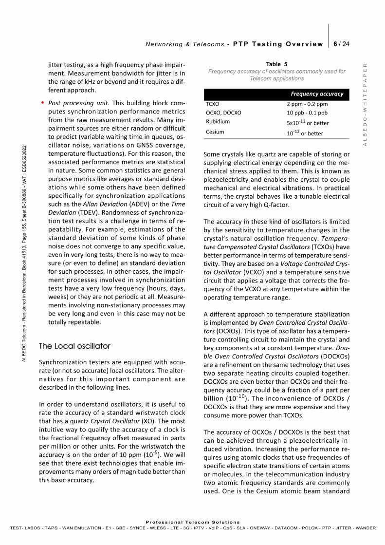
The accuracy of OCXOs / DOCXOs is the best thatcan be achieved through a piezoelectrically in‐duced vibration. Increasing the performance re‐quires using atomic clocks that use frequencies ofspecific electron state transitions of certain atomsor molecules. In the telecommunication industrytwo atomic frequency standards are commonlyused. One is the Cesium atomic beam standard
Table 5Frequency accuracy of oscillators commonly used for
Telecom applications
Frequency accuracy
TCXO 2 ppm ‐ 0.2 ppm
OCXO, DOCXO 10 ppb ‐ 0.1 ppb
Rubidium 5x10‐11 or better
Cesium 10‐12 or better

Network ing & Telecoms - P T P T e s t i n g O v e r v i e w 7 / 24
A L
B E
D O
- W
H I
T E
P A
P E
R
AL B
ED
O T
ele
com
- R
eg
iste
r ed
in B
arc
elo
na
, B
oo
k 41
61
3, P
age
15
5,
Sh
ee
t B-3
9 08
86
- V
AT
: E
SB
652
30
2 2
Pr o f es s i ona l Te l eco m S o l u t io ns
TEST- LABOS - TAPS - WAN EMULATION - E1 - GBE - SYNCE - WLESS - LTE - 3G - IPTV - VoIP - QoS - SLA - ONEWAY - DATACOM - POLQA - PTP - JITTER - WANDER
that uses the transition between two ground levelsof the hyperfine spectrum of the 133Cs atom equiv‐alent to 9,192,631,770 Hz. The second frequencystandard is based on Rubidium vapor cells that usean hyperfine transition of the 87Rb isotope to gen‐erate a frequency of 6,834,682,610.904 Hz.
The operation of an atomic clock is based on an in‐terrogation‐correction mechanism. A conventionalcrystal oscillator generates a frequency that is usedto interrogate a “physics package” that containsthe Cesium tube, the Rubidium vapor cell or anyother device based on atomic resonances. The“physics package” generates an error signal thatdepends on the de‐tuning of the test frequencyfrom the atomic resonance. The error signal is pro‐cessed and the result is used to control the fre‐quency generated by the crystal oscillator that isalso the clock output. The key piece of this setup isthe “Physics package” that behaves like an ex‐tremely high Q‐factor bandpass filter.
Aging effects are smaller in Cesium tubes than inRubidium clocks. For this reason the Rubidium fre‐quency standard is not suitable to operate in PRCs.However, Rubidium is well adapted for SSUs thatare usually disciplined by a primary source or GNSS.These clocks are also perfectly suited to test appli‐cations due to their low power consumption, com‐pact size and relatively low price. On the otherhand, Cesium tubes may offer frequency accura‐cies of 10‐12 or better and good long term frequen‐cy stability. These oscillators are therefore ideallysuited to be installed in PRCs.
A special type of vapor cell atomic clock is the socalled Chip‐Scale Atomic Clock (CSAC). CurrentCSAC implementations have the advantages of lowpower consumption and short warm up period.
Performance in terms of fractional frequency accu‐racy is around 0.1 ppb, in line with the best avail‐able OCXOs.
Cesium tubes are by no means the best atomicclocks available today. Research in accurate timesources is a very active field and current accuraciesachieved in new engines are in the range of 10‐15 orbetter. Of the new techniques used to improve theperformance of basic beam devices the most im‐portant is probably laser cooling of atoms. Usingcold atoms reduces the contributions to error fromthe Doppler effect, atom collisions and thermal ra‐diation, thus increasing the device accuracy by sev‐eral orders of magnitude.
Clock References
The correct way to assess how good a clock refer‐ence is depends on the metric to be measured, themeasurement bandwidth and, if disciplining isused, the local oscillator specifications. For exam‐ple, in jitter tests the measurement bandwidth isusually in the kilohertz range. To get a valid clockreference it is enough to apply a 10 Hz low pass fil‐ter to the test signal. The filtered test signal is per‐fectly suitable to be used as a clock reference in ajitter test. If the measurement bandwidth is to beextended to lower frequencies, this mechanism be‐comes more difficult to implement because thecutoff frequency in the low pass filter has to be re‐duced beyond practical limits. In the wander tests,the bandwidth is in the millihertz or microhertzrange. For this reason, the clock reference is an ad‐ditional input to the test. The test signal phase isexpected to be stable in the measurement band‐width.
If we now focus on external clock references, thereare three popular alternatives used in practical ap‐plications: PRCs, PRTCs and GNSS references. Thissection deals mainly with PRCs and PRTCs. As theperformance of GNSS references is strongly depen‐dent on how they are used to discipline the localoscillator, these are discussed in a section devotedto oscillator disciplining.
For many years, the best clocks available for tele‐communication applications have been PRCs. ThePRC wander is described in ITU‐T G.811 in terms ofthree interface independent metrics: The Maxi‐
Physicspackage
RF Synthesizer
Loop
Figure 3 Simplified block diagram of an atomic clock. The feedback from the physics package is used to tune a conventional oscillator such as an OCXO.
control
Oscillator
Clockoutput
Network ing & Telecoms - P T P T e s t i n g O v e r v i e w 8 / 24
A L
B E
D O
- W
H I
T E
P A
P E
R
AL B
ED
O T
ele
com
- R
eg
iste
r ed
in B
arc
elo
na
, B
oo
k 41
61
3, P
age
15
5,
Sh
ee
t B-3
9 08
86
- V
AT
: E
SB
652
30
2 2
Pr o f es s i ona l Te l eco m S o l u t io ns
TEST- LABOS - TAPS - WAN EMULATION - E1 - GBE - SYNCE - WLESS - LTE - 3G - IPTV - VoIP - QoS - SLA - ONEWAY - DATACOM - POLQA - PTP - JITTER - WANDER
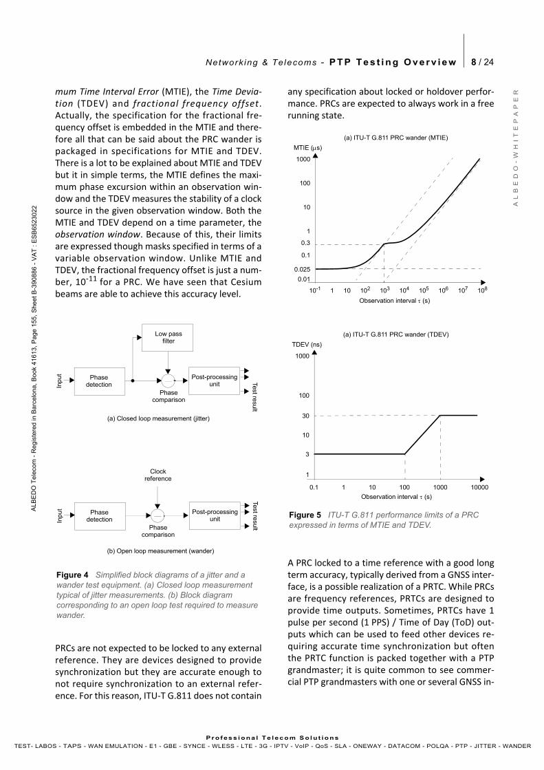
mum Time Interval Error (MTIE), the Time Devia‐tion (TDEV) and fractional frequency offset.Actually, the specification for the fractional fre‐quency offset is embedded in the MTIE and there‐fore all that can be said about the PRC wander ispackaged in specifications for MTIE and TDEV.There is a lot to be explained about MTIE and TDEVbut it in simple terms, the MTIE defines the maxi‐mum phase excursion within an observation win‐dow and the TDEV measures the stability of a clocksource in the given observation window. Both theMTIE and TDEV depend on a time parameter, theobservation window. Because of this, their limitsare expressed though masks specified in terms of avariable observation window. Unlike MTIE andTDEV, the fractional frequency offset is just a num‐ber, 10‐11 for a PRC. We have seen that Cesiumbeams are able to achieve this accuracy level.
PRCs are not expected to be locked to any externalreference. They are devices designed to providesynchronization but they are accurate enough tonot require synchronization to an external refer‐ence. For this reason, ITU‐T G.811 does not contain
any specification about locked or holdover perfor‐mance. PRCs are expected to always work in a freerunning state.
A PRC locked to a time reference with a good longterm accuracy, typically derived from a GNSS inter‐face, is a possible realization of a PRTC. While PRCsare frequency references, PRTCs are designed toprovide time outputs. Sometimes, PRTCs have 1pulse per second (1 PPS) / Time of Day (ToD) out‐puts which can be used to feed other devices re‐quiring accurate time synchronization but oftenthe PRTC function is packed together with a PTPgrandmaster; it is quite common to see commer‐cial PTP grandmasters with one or several GNSS in‐
Figure 4 Simplified block diagrams of a jitter and a wander test equipment. (a) Closed loop measurement typical of jitter measurements. (b) Block diagram corresponding to an open loop test required to measure wander.
Low pass
Post-processingunit
Phasecomparison
Test resu
lt
Input
filter
Phasedetection
Clock
Post-processingunit
Phasecomparison
Test resu
lt
Input
reference
Phasedetection
(a) Closed loop measurement (jitter)
(b) Open loop measurement (wander)
Figure 5 ITU-T G.811 performance limits of a PRC expressed in terms of MTIE and TDEV.
1000
0.01
MTIE (s)
101
1
102 103 104 105 10610-1
(a) ITU-T G.811 PRC wander (MTIE)
107 108
0.1
Observation interval (s)
100
10
0.3
0.025
1000
1
TDEV (ns)
1
10
10 1000.1
(a) ITU-T G.811 PRC wander (TDEV)
1000 10000
100
3
Observation interval (s)
30
Network ing & Telecoms - P T P T e s t i n g O v e r v i e w 9 / 24
A L
B E
D O
- W
H I
T E
P A
P E
R
AL B
ED
O T
ele
com
- R
eg
iste
r ed
in B
arc
elo
na
, B
oo
k 41
61
3, P
age
15
5,
Sh
ee
t B-3
9 08
86
- V
AT
: E
SB
652
30
2 2
Pr o f es s i ona l Te l eco m S o l u t io ns
TEST- LABOS - TAPS - WAN EMULATION - E1 - GBE - SYNCE - WLESS - LTE - 3G - IPTV - VoIP - QoS - SLA - ONEWAY - DATACOM - POLQA - PTP - JITTER - WANDER
puts. Before addressing the detailed description ofPRTCs, it is worth looking at time references andtheir properties more carefully.
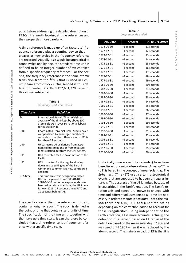
A time reference is made up of an (accurate) fre‐quency reference plus a counting device that in‐creases as new cycles in the frequency referenceare recorded. Actually, as it would be unpractical tocount cycles one by one, the standard time unit isdefined to be an integer number of cycles takenfrom a specific frequency reference. For the sec‐ond, the frequency reference is the same atomictransition from the 133Cs that is used in Cesi‐um‐beam atomic clocks. One second is thus de‐fined to contain exactly 9,192,631,770 cycles ofthis atomic reference.
The specification of the time reference must alsocontain an origin or epoch. The epoch is defined asthe point of time that contains zero units of time.The specification of the time unit, together withthe make up a time scale. It can therefore be con‐cluded that a time reference is a frequency refer‐ence with a specific time scale.
Historically time scales (the calendar) have beenbased in astronomical observations. Universal Time(UT) is based in the concept of mean solar day. TheEphemeris Time (ET) uses certain astronomicalevents that are supposed to happen at regular in‐tervals. The accuracy of the UT is limited because ofirregularities in the Earth’s rotation. The Earth’s ro‐tation axis and speed are known to change withtime and different adjustments to UT time are nec‐essary in order to maintain accuracy. That’s the rea‐son there are UT0, UT1 and UT2 time scalesdepending on the correction added to account forthese irregularities. Being independent of theEarth’s rotation, ET is more accurate. Actually, thedefinition of a second based on ET replaced thedefinition based on the mean solar day in 1956 andwas used until 1967 when it was replaced by theatomic second. The main drawback of ET is that it is
Table 6Commonly used time Scales
Time Scale Definition
TAI International Atomic Time. Weighted average of the time kept by about 200 atomic clocks in over 50 national labora‐tories worldwide.
UTC Coordinated Universal Time. Atomic scale compensated by an integer number of seconds so that the difference with UT1 is less than 0.9 seconds.
UT0 Uncorrected UT as derived from astro‐nomical observations or from measure‐ments carried out from the GPS system.
UT1 UT0 corrected for the polar motion of the Earth.
UT2 UT1 corrected for the regular slowing down and speeding up of the Earth in winter and summer. It is now considered obsolete.
GPS time This time scale was designed to match UTC in the period from 1980‐01‐01 to 1981‐06‐30 but as no leap seconds have been added since that date, the GPS time is now (2016) 17 seconds ahead UTC and 19 seconds behind TAI.
Table 7Leap seconds added
UTC Date Amount TAI to UTC offset
1972‐06‐30 +1 second 11 seconds
1972‐12‐31 +1 second 12 seconds
1973‐12‐31 +1 second 13 seconds
1974‐12‐31 +1 second 14 seconds
1975‐12‐31 +1 second 15 seconds
1976‐12‐31 +1 second 16 seconds
1977‐12‐31 +1 second 17 seconds
1978‐12‐31 +1 second 18 seconds
1979‐12‐31 +1 second 19 seconds
1981‐06‐30 +1 second 20 seconds
1982‐06‐30 +1 second 21 seconds
1983‐06‐30 +1 second 22 seconds
1985‐06‐30 +1 second 23 seconds
1987‐12‐31 +1 second 24 seconds
1989‐12‐31 +1 second 25 seconds
1990‐12‐31 +1 second 26 seconds
1992‐06‐30 +1 second 27 seconds
1993‐06‐30 +1 second 28 seconds
1994‐06‐30 +1 second 29 seconds
1995‐12‐31 +1 second 30 seconds
1997‐06‐30 +1 second 31 seconds
1998‐12‐31 +1 second 32 seconds
2005‐12‐31 +1 second 33 seconds
2008‐12‐31 +1 second 34 seconds
2012‐06‐30 +1 second 35 seconds
2015‐06‐30 +1 second 36 seconds
Network ing & Telecoms - P T P T e s t i n g O v e r v i e w 10 / 24
A L
B E
D O
- W
H I
T E
P A
P E
R
AL B
ED
O T
ele
com
- R
eg
iste
r ed
in B
arc
elo
na
, B
oo
k 41
61
3, P
age
15
5,
Sh
ee
t B-3
9 08
86
- V
AT
: E
SB
652
30
2 2
Pr o f es s i ona l Te l eco m S o l u t io ns
TEST- LABOS - TAPS - WAN EMULATION - E1 - GBE - SYNCE - WLESS - LTE - 3G - IPTV - VoIP - QoS - SLA - ONEWAY - DATACOM - POLQA - PTP - JITTER - WANDER
necessary to wait for astronomical events to hap‐pen to adjust the time. Atomic time is readily at anytime.
Time scales based on astronomical observationswere replaced by time scales based on atomic timeat the end of 1950s. Coordinated Universal Time(UTC) is an atomic time scale defined to match theUT2 time (and later UT1) within a certain error mar‐gin. Before 1972 the adjustment mechanisms in‐cluded slight modifications in the standard secondlength and small phase adjustments of 1/10 of sec‐ond. From 1972 onwards the leap second mecha‐nism was agreed upon; through this mechanism,one day (always chosen to be January 1st or June30th) is allowed to have one more or one less sec‐ond than an standard day. The leap second mecha‐nism has been applied 26 times to compensate forthe offset measured from UT1. Closely related withthe UTC time scale, there is the International Atom‐ic Time (TAI) scale which is exactly the same as UTCtime but it contains no leap seconds. The TAI timewas adjusted 10 seconds ahead of UTC at the begin‐ning of 1972. This means that the current offset(2016) is 36 seconds. This difference accounts forthe slow down of Earth’s rotation in the last halfcentury.
A full description of the epoch in use for differenttime scales would be quite complex. For our pur‐poses it is enough to state that PTP uses the TAItime scale and the epoch is 00:00:00 01/01/1970.This selection is done so that the POSIX algorithmapplied to the PTP 0 seconds time stamp gives thedate and time mentioned before. PTP also allowsthe use of arbitrary time scales to account for net‐work administrators willing to use a different ep‐och. The GPS system starts counting time from00:00:00 06/01/1980 (6th of January) but as no leapseconds applied to the GPS time, this time scale iscurrently 17 seconds ahead of UTC.
Specification of a PRTC is the subject of ITU‐TG.8272. Unlike PRCs, PRTCs are expected to be dis‐ciplined by at least one time reference. For this rea‐son, PRTC specifications are given not only for freerunning status but also for locked and holdover.When locked to a GNSS or other reference, thePRTC specifications are almost identical to the PRCbut the requirement about fractional frequency
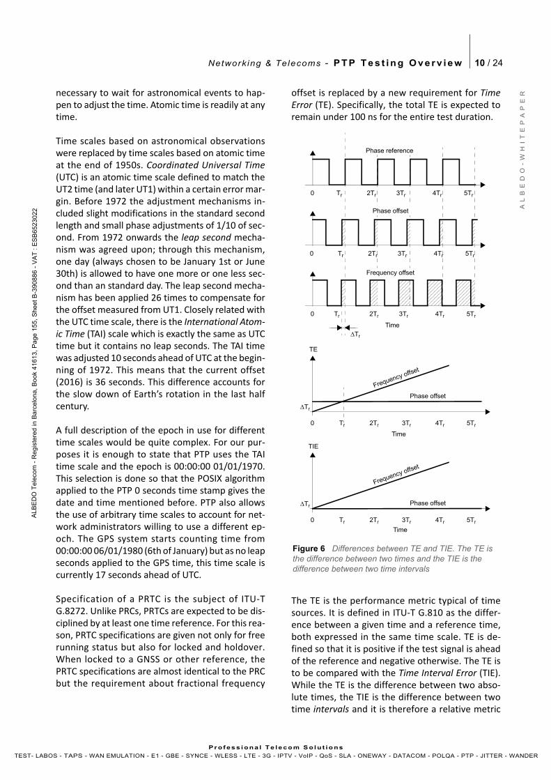
offset is replaced by a new requirement for TimeError (TE). Specifically, the total TE is expected toremain under 100 ns for the entire test duration.
The TE is the performance metric typical of timesources. It is defined in ITU‐T G.810 as the differ‐ence between a given time and a reference time,both expressed in the same time scale. TE is de‐fined so that it is positive if the test signal is aheadof the reference and negative otherwise. The TE isto be compared with the Time Interval Error (TIE).While the TE is the difference between two abso‐lute times, the TIE is the difference between twotime intervals and it is therefore a relative metric
Figure 6 Differences between TE and TIE. The TE is the difference between two times and the TIE is the difference between two time intervals
Phase reference
Tr 2Tr 3Tr0 4Tr 5Tr
Tr 2Tr 3Tr0 4Tr 5Tr
Tr 2Tr 3Tr0 4Tr 5Tr
Phase offset
Frequency offset
Time
Tr 2Tr 3Tr0 4Tr 5Tr
Tr
TE
Tr
Frequency offset
Phase offset
Tr 2Tr 3Tr0 4Tr 5Tr
TIE
Tr
Frequency offset
Phase offset
Time
Time
Network ing & Telecoms - P T P T e s t i n g O v e r v i e w 11 / 24
A L
B E
D O
- W
H I
T E
P A
P E
R
AL B
ED
O T
ele
com
- R
eg
iste
r ed
in B
arc
elo
na
, B
oo
k 41
61
3, P
age
15
5,
Sh
ee
t B-3
9 08
86
- V
AT
: E
SB
652
30
2 2
Pr o f es s i ona l Te l eco m S o l u t io ns
TEST- LABOS - TAPS - WAN EMULATION - E1 - GBE - SYNCE - WLESS - LTE - 3G - IPTV - VoIP - QoS - SLA - ONEWAY - DATACOM - POLQA - PTP - JITTER - WANDER
independent of the epoch. The TIE is very usefulperformance metric for frequency deployments(the MTIE and TDEV are derived from the TIE) butin time and phase applications the TIE has to be re‐placed by the TE.
The |TE| < 100 ns requirement is related with a fur‐ther MTIE < 100 ns limit (the opposite is not true,an MTIE < 100 ns limit does necessarily require theTE to be under 100 ns). Actually, the ITU‐T G.8272MTIE mask is the intersection of the MTIE < 100 nsregion and the ITU‐T G.811 PRC mask. The TDEV re‐quirement is exactly the same for a PRC and aPRTC. From this point of view, it can be said thatthe PRTC requirements are stronger than the PRCoperation limits but it must not be forgotten thatPRTCs are specified when they are operating inlocked status and PRCs are specified in free runningstatus. The requirements for both are thus not di‐rectly comparable.
Oscillator Disciplining
A synchronization test set is expected to measurethe performance level of accurate timing sourcessuch as Cesium PRCs that are often used to supplysynchronization to large networks. The question is,how can a synchronization tester measure the ac‐curacy of a clock that is potentially much betterthan its own local oscillator? This is done throughan external reference, or still better, by a combina‐tion of an external reference and the local clockachieved through a process known as oscillator dis‐ciplining. Even with oscillator disciplining it is notuncommon that the test signal is of the same nom‐inal accuracy level as the local (disciplined) oscilla‐tor. A typical example is the measurement of a PRCusing another PRC clock reference. In this case, apass result is certainly reliable but the same cannotbe said about a fail because there is no way to sep‐arate the phase / frequency degradations in thetest signal and in the reference. As a result, wemust be prepared for uncertain results in telecomsynchronization tests.
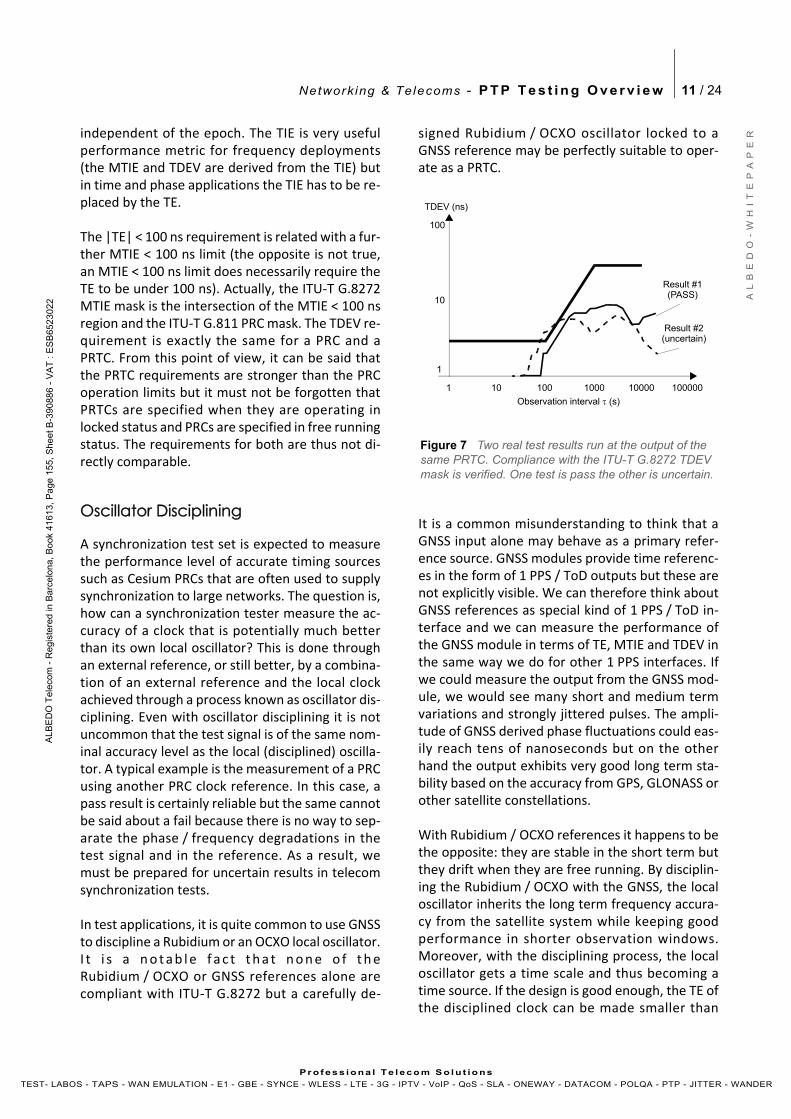
In test applications, it is quite common to use GNSSto discipline a Rubidium or an OCXO local oscillator.I t i s a n o t a b l e f a c t t h a t n o n e o f t h eRubidium / OCXO or GNSS references alone arecompliant with ITU‐T G.8272 but a carefully de‐
signed Rubidium / OCXO oscillator locked to aGNSS reference may be perfectly suitable to oper‐ate as a PRTC.
It is a common misunderstanding to think that aGNSS input alone may behave as a primary refer‐ence source. GNSS modules provide time referenc‐es in the form of 1 PPS / ToD outputs but these arenot explicitly visible. We can therefore think aboutGNSS references as special kind of 1 PPS / ToD in‐terface and we can measure the performance ofthe GNSS module in terms of TE, MTIE and TDEV inthe same way we do for other 1 PPS interfaces. Ifwe could measure the output from the GNSS mod‐ule, we would see many short and medium termvariations and strongly jittered pulses. The ampli‐tude of GNSS derived phase fluctuations could eas‐ily reach tens of nanoseconds but on the otherhand the output exhibits very good long term sta‐bility based on the accuracy from GPS, GLONASS orother satellite constellations.
With Rubidium / OCXO references it happens to bethe opposite: they are stable in the short term butthey drift when they are free running. By disciplin‐ing the Rubidium / OCXO with the GNSS, the localoscillator inherits the long term frequency accura‐cy from the satellite system while keeping goodperformance in shorter observation windows.Moreover, with the disciplining process, the localoscillator gets a time scale and thus becoming atime source. If the design is good enough, the TE ofthe disciplined clock can be made smaller than
Figure 7 Two real test results run at the output of the same PRTC. Compliance with the ITU-T G.8272 TDEV mask is verified. One test is pass the other is uncertain.
1
TDEV (ns)
1
10
10 100 1000 10000
100
Observation interval (s)
100000
Result #1
Result #2
(PASS)
(uncertain)
Network ing & Telecoms - P T P T e s t i n g O v e r v i e w 12 / 24
A L
B E
D O
- W
H I
T E
P A
P E
R
AL B
ED
O T
ele
com
- R
eg
iste
r ed
in B
arc
elo
na
, B
oo
k 41
61
3, P
age
15
5,
Sh
ee
t B-3
9 08
86
- V
AT
: E
SB
652
30
2 2
Pr o f es s i ona l Te l eco m S o l u t io ns
TEST- LABOS - TAPS - WAN EMULATION - E1 - GBE - SYNCE - WLESS - LTE - 3G - IPTV - VoIP - QoS - SLA - ONEWAY - DATACOM - POLQA - PTP - JITTER - WANDER
100 ns and the MTIE and TDEV could be con‐strained within the ITU‐T G.8272 pass region. Thedisciplined oscillator then effectively becomes aPRTC.
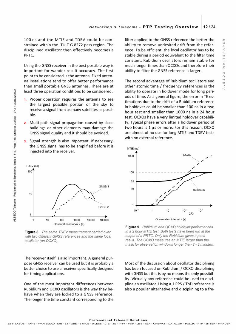
Using the GNSS receiver in the best possible way isimportant for wander result accuracy. The firstpoint to be considered is the antenna. Fixed anten‐na installations tend to offer better performancethan small portable GNSS antennas. There are atleast three operation conditions to be considered:
1. Proper operation requires the antenna to seethe largest possible portion of the sky toreceive a signal from as many satellites as possi‐ble.
2. Multi‐path signal propagation caused by closebuildings or other elements may damage theGNSS signal quality and it should be avoided.
3. Signal strength is also important. If necessary,the GNSS signal has to be amplified before it isinjected into the receiver.
The receiver itself is also important. A general pur‐pose GNSS receiver can be used but it is probably abetter choice to use a receiver specifically designedfor timing applications.
One of the most important differences betweenRubidium and OCXO oscillators is the way they be‐have when they are locked to a GNSS reference.The longer the time constant corresponding to the
filter applied to the GNSS reference the better theability to remove undesired drift from the refer‐ence. To be efficient, the local oscillator has to bestable during a period equivalent to the filter timeconstant. Rubidium oscillators remain stable formuch longer times than OCXOs and therefore theirability to filter the GNSS reference is larger.
The second advantage of Rubidium oscillators andother atomic time / frequency references is theability to operate in holdover mode for long peri‐ods of time. As a general figure, the error in TE es‐timations due to the drift of a Rubidium referencein holdover could be smaller than 100 ns in a twohour test and smaller than 1000 ns in a 24 hourtest. OCXOs have a very limited holdover capabili‐ty. Typical phase errors after a holdover period oftwo hours is 1 s or more. For this reason, OCXOare almost of no use for long MTIE and TDEV testswith no external reference.
Most of the discussion about oscillator disciplininghas been focused on Rubidium / OCXO discipliningwith GNSS but this is by no means the only possibil‐ity. Virtually any reference could be used to disci‐pline an oscillator. Using a 1 PPS / ToD reference isalso a popular alternative and disciplining to a fre‐
Figure 8 The same TDEV measurement carried over with two different GNSS references and the same local oscillator (an OCXO).
1
TDEV (ns)
1
10
10 100 1000 10000
100
Observation interval (s)
100000
GNSS 1
GNSS 210
273
1000
10
MTIE (ns)
1
100
10210-1 103
25
Observation interval (s)
Figure 9 Rubidium and OCXO holdover performances in a 2 hour MTIE test. Both tests have been run at the output of a PRTC. Only the Rubidium gives a pass result. The OCXO measures an MTIE larger than the mask for observation windows longer than 2 - 3 minutes.
1
OCXO
Rubidium
Network ing & Telecoms - P T P T e s t i n g O v e r v i e w 13 / 24
A L
B E
D O
- W
H I
T E
P A
P E
R
AL B
ED
O T
ele
com
- R
eg
iste
r ed
in B
arc
elo
na
, B
oo
k 41
61
3, P
age
15
5,
Sh
ee
t B-3
9 08
86
- V
AT
: E
SB
652
30
2 2
Pr o f es s i ona l Te l eco m S o l u t io ns
TEST- LABOS - TAPS - WAN EMULATION - E1 - GBE - SYNCE - WLESS - LTE - 3G - IPTV - VoIP - QoS - SLA - ONEWAY - DATACOM - POLQA - PTP - JITTER - WANDER
quency reference (either periodic such as 1544kHz, 2048 kHz or 10 MHz or non‐periodic such as1544 kb/s 2048 kb/s) is possible as well.
Disciplining to 1 PPS / ToD references has manysimilarities with GNSS disciplining. The main differ‐ence is that 1 PPS / ToD may be the output of ahigh performance network clock such as a PRTC.These signals are normally “cleaner” that GNSS ref‐erences and therefore they do not require thesame level of sophisticated filtering applied toGNSS inputs. An important point about 1 PPS / ToDreferences is that they are slow signals. They can beused to adjust the local oscillator only once per sec‐ond, which is the 1 PPS frequency. The local oscilla‐tor must remain stable during the time periodbetween two consecutive adjustments (1 second).This is applicable to Rubidium oscillators andOCXOs but not TCXOs. Frequency references canbe used with all kinds of local oscillators, includingTCXOs but they cannot be used for time and phaseapplications, unfortunately.
3. BASIC TESTING SCENARIOS
Synchronization tests may be classified as emula‐tion and monitoring tests. In an emulation test, thetest set behaves as specific network element (or agroup of elements) and sometimes it replaces thisentity. Usually the test set is not required to repli‐cate all the functionality of the emulated equip‐ment, but on the other hand the tester is able tocarry out some diagnostics that are beyond the em‐ulated equipment capabilities. As an example, atest unit may be unable to manage hundreds of si‐multaneous unicast PTP sessions but it may carryout advanced TE, MTIE and TDEV tests over a re‐duced set of these sessions. The purpose of a mon‐itoring test is to get information about the tested
entities without disturbing them. A network moni‐tor should not generate any traffic and it shouldnot disturb existing traffic. It must rely on the traf‐fic captured from the devices under test throughone or various interfaces.
Many PTP tests could be run both in endpoint or inmonitoring modes, but generally, gathering thedata required to compute all the important perfor‐mance metrics is more difficult in passive monitor‐ing mode because the tester has to interceptvarious PTP message flows including the mas‐
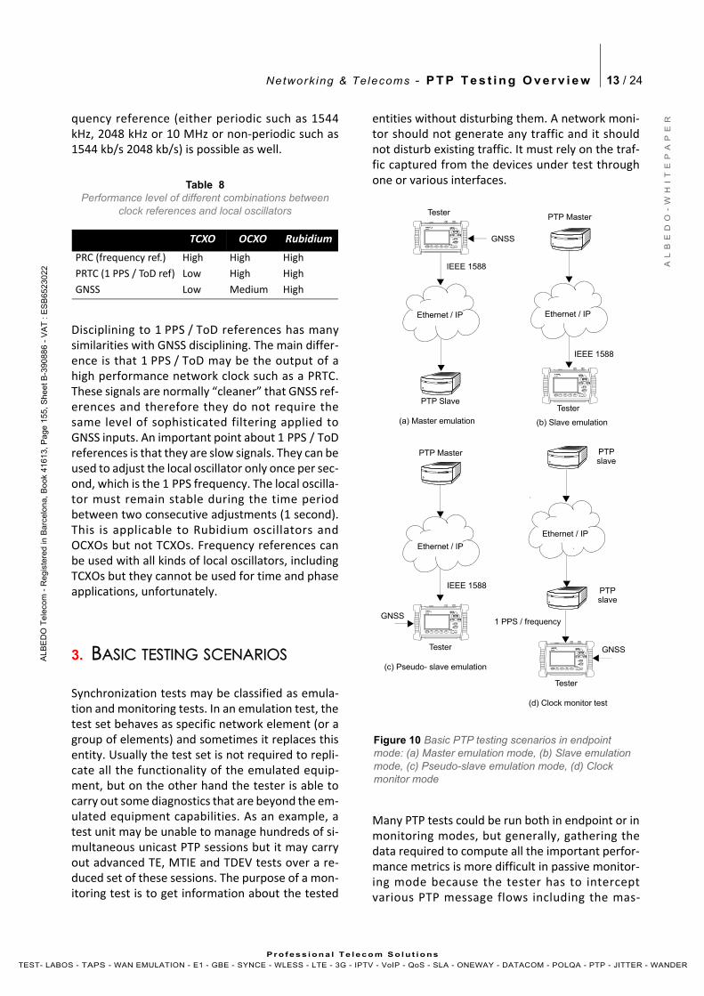
Table 8Performance level of different combinations between
clock references and local oscillators
TCXO OCXO Rubidium
PRC (frequency ref.) High High High
PRTC (1 PPS / ToD ref) Low High High
GNSS Low Medium High
Figure 10 Basic PTP testing scenarios in endpoint mode: (a) Master emulation mode, (b) Slave emulation mode, (c) Pseudo-slave emulation mode, (d) Clock monitor mode
LEDS F1 F2 F3 F4
EVENTRUN
HOME SUM
BACK
PWRDC
ENTER
LEDS F1 F2 F3 F4
EVENT
RUN
HOME SUM
BACK
PWRDC
ENTER
LEDS F1 F2 F3 F4
EVENT
RUN
HOME SUM
BACK
PWRDC
ENTER
LEDS F1 F2 F3 F4
EVENT
RUN
HOME SUM
BACK
PWRDC
ENTER
GNSS
Ethernet / IP Ethernet / IP
Ethernet / IP
Ethernet / IP
(a) Master emulation (b) Slave emulation
(c) Pseudo- slave emulation
(d) Clock monitor test
IEEE 1588
IEEE 1588
IEEE 1588
1 PPS / frequency
Tester
PTP SlaveTester
PTP Master
PTP Master
Tester
Tester
PTPslave
PTPslave
GNSS
GNSS
Network ing & Telecoms - P T P T e s t i n g O v e r v i e w 14 / 24
A L
B E
D O
- W
H I
T E
P A
P E
R
AL B
ED
O T
ele
com
- R
eg
iste
r ed
in B
arc
elo
na
, B
oo
k 41
61
3, P
age
15
5,
Sh
ee
t B-3
9 08
86
- V
AT
: E
SB
652
30
2 2
Pr o f es s i ona l Te l eco m S o l u t io ns
TEST- LABOS - TAPS - WAN EMULATION - E1 - GBE - SYNCE - WLESS - LTE - 3G - IPTV - VoIP - QoS - SLA - ONEWAY - DATACOM - POLQA - PTP - JITTER - WANDER
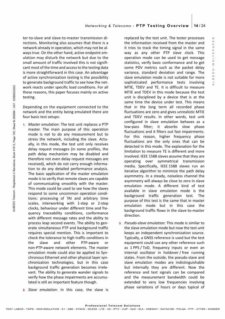
ter‐to‐slave and slave‐to‐master transmission di‐rections. Monitoring also assumes that there is anetwork already in operation, which may not be al‐ways true. On the other hand, active endpoint em‐ulation may disturb the network but due to thesmall amount of traffic involved this is not signifi‐cant most of the time and access to the testing datais more straightforward in this case. An advantageof active synchronization testing is the possibilityto generate background traffic to see how the net‐work reacts under specific load conditions. For allthese reasons, this paper focuses mainly on activetesting.
Depending on the equipment connected to thenetwork and the entity being emulated there arefour basic test setups:
1. Master emulation: The test unit replaces a PTPmaster. The main purpose of this operationmode is not to do any measurement but tostress the network, including the slave. Actu‐ally, in this mode, the test unit only receivesdelay request messages (in some profiles, thepath delay mechanism may be disabled andtherefore not even delay request messages arereceived), which do not carry enough informa‐tion to do any detailed performance analysis.The basic application of the master emulationmode is to verify that remote slaves are capableof communicating smoothly with the master.This mode could be used to see how the slavesrespond to some uncommon operation condi‐tions: processing of TAI and arbitrary timescales, interworking with 1‐step or 2‐stepclocks, behaviour under different time and fre‐quency traceability conditions, conformancewith different message rates and the ability toprocess leap second events. The ability to gen‐erate simultaneous PTP and background trafficrequires special mention. This is important tocheck the tolerance to high traffic conditions inthe slave and other PTP‐aware ornon‐PTP‐aware network elements. The masteremulation mode could also be applied to Syn‐chronous Ethernet and other physical layer syn‐chronization technologies, but in this casebackground traffic generation becomes irrele‐vant. The ability to generate wander signals toverify how the phase impairments are accumu‐lated is still an important feature though.
2. Slave emulation: In this case, the slave is
replaced by the test unit. The tester processesthe information received from the master andit tries to track the timing signal in the sameway as any other PTP slave clock. Thisoperation mode can be used to get messagestatistics, verify basic conformance and to getsome PDV metrics such as the packet delayvariance, standard deviation and range. Theslave emulation mode is not suitable for moresophisticated performance tests involvingMTIE, TDEV and TE. It is difficult to measureMTIE and TDEV in this mode because the testunit is disciplined by a device that is at thesame time the device under test. This meansthat in the long term all recorded phasefluctuations are zero and gives unrealistic MTIEand TDEV results. In other words, test unitconfigured in slave emulation behaves as alow‐pass filter; it absorbs slow phasefluctuations and it filters out fast impairments.For this reason, higher frequency phasefluctuations are the only ones that can bedetected in this mode. The explanation for thelimitation to measure TE is different and moreinvolved. IEEE 1588 slaves assume that they areoperating over symmetrical transmissionmedia. Specifically, IEEE 1588 slaves run aniterative algorithm to minimize the path delayasymmetry. In a steady, noiseless channel theasymmetry will always be close to zero in slaveemulation mode. A different kind of testavailable in slave emulation mode is thebackground traffic generation test. Thepurpose of this test is the same that in masteremulation mode but in this case thebackground traffic flows in the slave‐to‐masterdirection.
3. Pseudo‐slave emulation: This mode is similar tothe slave emulation mode but now the test unitkeeps an independent synchronization source.Typically, a GNSS reference is used but the testequipment could use any other reference suchas 1 PPS / ToD, frequency inputs or even aninternal oscillator in holdover / free runningstates. From the outside, the pseudo‐slave andslave emulation modes are indistinguishablebut internally they are different. Now thereference and test signals can be comparedand the measurement bandwidth could beextended to very low frequencies involvingphase variations of hours or days typical of
Network ing & Telecoms - P T P T e s t i n g O v e r v i e w 15 / 24
A L
B E
D O
- W
H I
T E
P A
P E
R
AL B
ED
O T
ele
com
- R
eg
iste
r ed
in B
arc
elo
na
, B
oo
k 41
61
3, P
age
15
5,
Sh
ee
t B-3
9 08
86
- V
AT
: E
SB
652
30
2 2
Pr o f es s i ona l Te l eco m S o l u t io ns
TEST- LABOS - TAPS - WAN EMULATION - E1 - GBE - SYNCE - WLESS - LTE - 3G - IPTV - VoIP - QoS - SLA - ONEWAY - DATACOM - POLQA - PTP - JITTER - WANDER
MTIE and TDEV tests. If a time reference is used(1 PPS / ToD, GNSS) the TE could be computedas well. Finally, the pseudo‐slave operationmode is also compatible with backgroundtraffic generation. This feature could be used tocheck any change in the TE, MTIE and TDEVdepending on the traffic load.
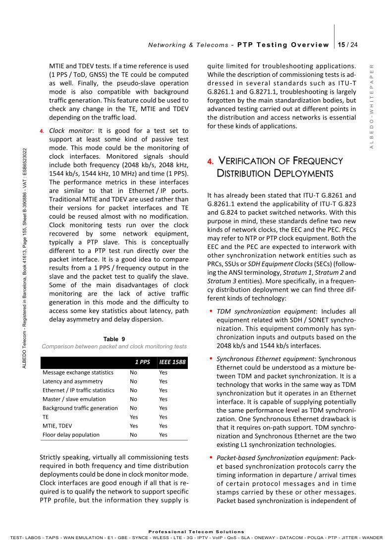
4. Clock monitor: It is good for a test set tosupport at least some kind of passive testmode. This mode could be the monitoring ofclock interfaces. Monitored signals shouldinclude both frequency (2048 kb/s, 2048 kHz,1544 kb/s, 1544 kHz, 10 MHz) and time (1 PPS).The performance metrics in these interfacesare similar to that in Ethernet / IP ports.Traditional MTIE and TDEV are used rather thantheir versions for packet interfaces and TEcould be reused almost with no modification.Clock monitoring tests run over the clockrecovered by some network equipment,typically a PTP slave. This is conceptuallydifferent to a PTP test run directly over thepacket interface. It is a good idea to compareresults from a 1 PPS / frequency output in theslave and the packet test to qualify the slave.Some of the main disadvantages of clockmonitoring are the lack of active trafficgeneration in this mode and the difficulty toaccess some key statistics about latency, pathdelay asymmetry and delay dispersion.
Strictly speaking, virtually all commissioning testsrequired in both frequency and time distributiondeployments could be done in clock monitor mode.Clock interfaces are good enough if all that is re‐quired is to qualify the network to support specificPTP profile, but the information they supply is
quite limited for troubleshooting applications.While the description of commissioning tests is ad‐dressed in several standards such as ITU‐TG.8261.1 and G.8271.1, troubleshooting is largelyforgotten by the main standardization bodies, butadvanced testing carried out at different points inthe distribution and access networks is essentialfor these kinds of applications.
4. VERIFICATION OF FREQUENCY DISTRIBUTION DEPLOYMENTS
It has already been stated that ITU‐T G.8261 andG.8261.1 extend the applicability of ITU‐T G.823and G.824 to packet switched networks. With thispurpose in mind, these standards define two newkinds of network clocks, the EEC and the PEC. PECsmay refer to NTP or PTP clock equipment. Both theEEC and the PEC are expected to interwork withother synchronization network entities such asPRCs, SSUs or SDH Equipment Clocks (SECs) (follow‐ing the ANSI terminology, Stratum 1, Stratum 2 andStratum 3 entities). More specifically, in a frequen‐cy distribution deployment we can find three dif‐ferent kinds of technology:
• TDM synchronization equipment: Includes allequipment related with SDH / SONET synchro‐nization. This equipment commonly has syn‐chronization inputs and outputs based on the2048 kb/s and 1544 kb/s interfaces.
• Synchronous Ethernet equipment: SynchronousEthernet could be understood as a mixture be‐tween TDM and packet synchronization. It is atechnology that works in the same way as TDMsynchronization but it operates in an Ethernetinterface. It is capable of supplying potentiallythe same performance level as TDM synchroni‐zation. One Synchronous Ethernet drawback isthat it requires on‐path support. TDM synchro‐nization and Synchronous Ethernet are the twoexisting L1 synchronization technologies.
• Packet‐based Synchronization equipment: Pack‐et based synchronization protocols carry thetiming information in departure / arrival timesof certain protocol messages and in timestamps carried by these or other messages.Packet based synchronization is independent of
Table 9Comparison between packet and clock monitoring tests
1 PPS IEEE 1588
Message exchange statistics No Yes
Latency and asymmetry No Yes
Ethernet / IP traffic statistics No Yes
Master / slave emulation No Yes
Background traffic generation No Yes
TE Yes Yes
MTIE, TDEV Yes Yes
Floor delay population No Yes
Network ing & Telecoms - P T P T e s t i n g O v e r v i e w 16 / 24
A L
B E
D O
- W
H I
T E
P A
P E
R
AL B
ED
O T
ele
com
- R
eg
iste
r ed
in B
arc
elo
na
, B
oo
k 41
61
3, P
age
15
5,
Sh
ee
t B-3
9 08
86
- V
AT
: E
SB
652
30
2 2
Pr o f es s i ona l Te l eco m S o l u t io ns
TEST- LABOS - TAPS - WAN EMULATION - E1 - GBE - SYNCE - WLESS - LTE - 3G - IPTV - VoIP - QoS - SLA - ONEWAY - DATACOM - POLQA - PTP - JITTER - WANDER
the physical transmission layer. The most im‐portant packet based synchronization protocolsare PTP and NTP but this document deals exclu‐sively with PTP, by far the most accurate of thetwo. PTP works better with on‐path support butit may work without it. This is a big advantage ifpacket based synchronization is to be deployedin existing networks.
Verification of frequency distribution deploymentsin packet switched networks is pretty much thesame as in circuit switched networks. Most opera‐tion limits and masks are re‐used and some othersare only slightly modified. For example, the frac‐tional frequency accuracy for a PRC is 10‐11 and afree running SSU (ITU‐T G.812 Type I clock) has fre‐quency accuracy of 16 ppb or better. These are al‐most psychological operational limits to rate theoperational performance of network clocks. Theselimits are still relevant in packet switched net‐works.
Standards define performance limits both for iso‐lated devices and for networks. The limits we havestudied for PRCs and PRTCs are examples of deviceoperation limits but no specific limit for networkshas been described so far. The next paragraphs dealwith this subject. The main reference for Synchro‐nous Ethernet network operation limits is ITU‐TG.8261. Limits for packet‐based networks are de‐scribed in ITU‐T G.8261.1.
Synchronous Ethernet
Synchronous Ethernet is an ITU‐T standard thatprovides mechanisms to transfer frequency overthe Ethernet physical layer or L1, which can then bemade traceable to an external source such as a net‐work clock. As such, the Ethernet link may be used
and considered part of the synchronization net‐work. Currently, Synchronous Ethernet is seen asan important building block for accurate frequencyover packet switched network. A limitation of Syn‐chronous Ethernet is the inability to transfer time.It can be used only for frequency synchronization.
A key topic in Synchronous Ethernet is the defini‐tion of the mechanisms necessary to achieve inter‐working between SDH / SONET and Ethernetequipment. These mechanisms and procedures arefound fundamentally in three different recommen‐dations: ITU‐T G.8261, G.8262 and G.8264:
• Extension of the synchronization network to in‐clude Ethernet as a building block (ITU‐TG.8261) enables Synchronous Ethernet net‐work equipment to be connected to the samesynchronization network as SDH / SONET. Syn‐chronization for SDH / SONET can be transport‐ed over Ethernet and the opposite is also true.
• ITU‐T G.8262 defines the EEC to be compatiblewith other SDH clocks. EECs are based on ITU‐TG.813 clocks and they are defined in terms ofaccuracy, noise transfer, holdover performance,noise tolerance, and noise generation. Whilethe IEEE 802.3 standard specifies Ethernetclocks to be within ±100 ppm ITU‐T G.8262specifies EEC accuracy to be within ±4.6 ppm.Additionally, PRC traceability of the interface isachievable by disciplining the EEC.
• ITU‐T G.8264 extends the usability of the ITU‐TG.781 SSM by Synchronous Ethernet equip‐ment. The SSM contains an indication of thequality level of the clock that is driving the syn‐chronization chain. The Ethernet Synchroniza‐tion Message Channel (ESMC) is used forpropagation of the SSM through the Synchro‐nous Ethernet network.
The basic difference between a conventionalEthernet and a Synchronous Ethernet network in‐terface card is that the Synchronous Ethernet cardis prepared to accept external timing or to supplytiming to other subsystems. On the other hand, theconventional card is relegated to operate with itsown ±100 ppm internal clock. Note that the con‐ventional card is still able to use the clock from anexternal subsystem (for example the CPU) for datatransmission but data reception is not coupled tothe transmitter clock and it is also uncoupled to
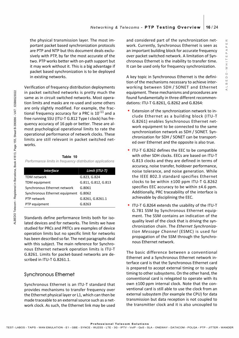
Table 10Performance limits in frequency distribution applications
Interface Limit (ITU‐T)
TDM network G.823, G.824
TDM equipment G.811, G.812, G.813
Synchronous Ethernet network G.8061
Synchronous Ethernet equipment G.8062
PTP network G.8261, G.8261.1
PTP equipment G.8263
Network ing & Telecoms - P T P T e s t i n g O v e r v i e w 17 / 24
A L
B E
D O
- W
H I
T E
P A
P E
R
AL B
ED
O T
ele
com
- R
eg
iste
r ed
in B
arc
elo
na
, B
oo
k 41
61
3, P
age
15
5,
Sh
ee
t B-3
9 08
86
- V
AT
: E
SB
652
30
2 2
Pr o f es s i ona l Te l eco m S o l u t io ns
TEST- LABOS - TAPS - WAN EMULATION - E1 - GBE - SYNCE - WLESS - LTE - 3G - IPTV - VoIP - QoS - SLA - ONEWAY - DATACOM - POLQA - PTP - JITTER - WANDER
other transmitters in the network. This last featureis the one that defines IEEE 802.3 Ethernet as anasynchronous technology.
Synchronous Ethernet’s ability to accept or givetiming signals makes this technology suitable forhierarchical synchronization. Here, the key ele‐ment is the EEC which enables Ethernet nodes toaccept or supply synchronization to other Ethernetor TDM equipment. Thanks to this property, Syn‐chronous Ethernet becomes a new building blockof the synchronization network.
MTIE and TDEV
MTIE and TDEV are the most important perfor‐mance metrics in Synchronous Ethernet and PTPfrequency distribution deployments. If there arefractional frequency offset requirements, these canbe built into the MTIE mask.
MTIE and TDEV network limits for SynchronousEthernet are given in ITU‐T G.8261. MTIE and TDEVare computed in the same way as in any TDM inter‐
face but the Synchronous Ethernet test is carriedout over a 1000BASE‐T, 1000BASE‐X or any otherEthernet interface compatible with this technology.Actually, ITU‐T G.8261 extends the applicability ofITU‐T G.823 and G.824 to Synchronous Ethernet.Performance of Synchronous Ethernet deploy‐ments do not depend on the load and therefore themeasurement could be run without worrying abouttraffic conditions.
For packet synchronization the situation is quitesimilar. Different limits apply if the packet networkis to totally or partially replace a TDM segment or ifpacket synchronization is to be used to deliver tim‐ing to specific application. In the former situation,packet synchronization is expected to provide thesame performance as Synchronous Ethernet andtherefore the same operational limits in terms ofMTIE and TDEV apply. If packet synchronization is
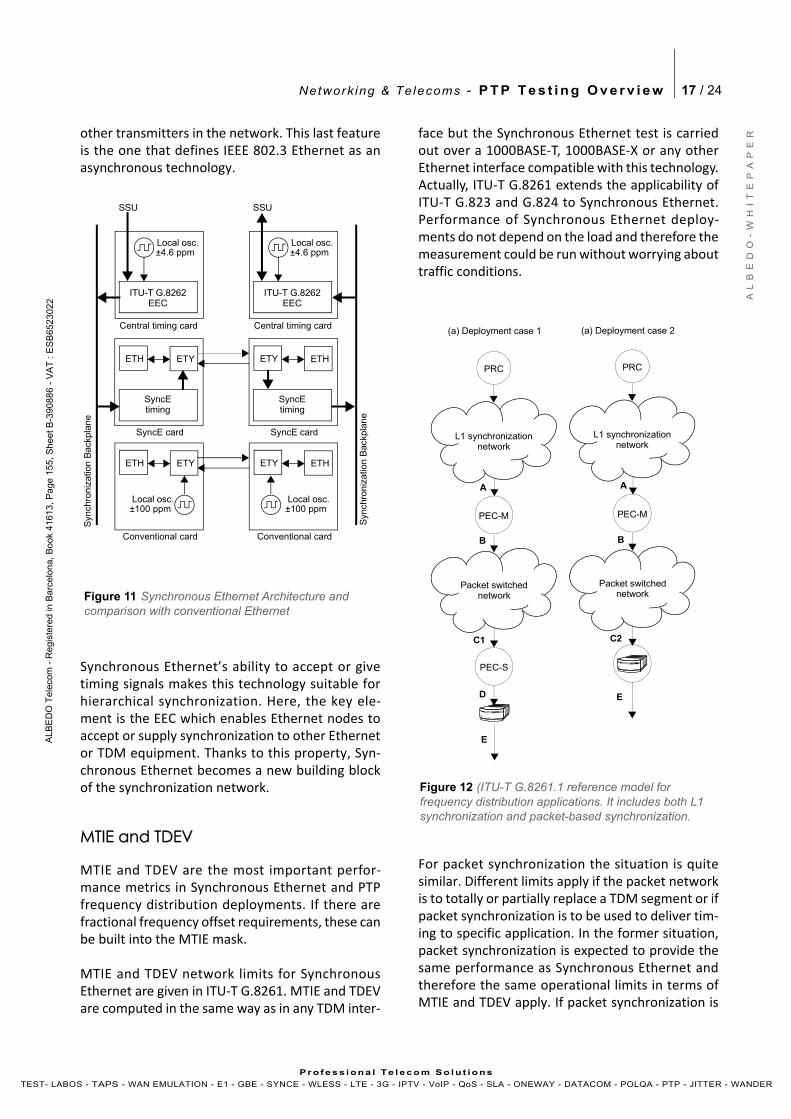
Figure 11 Synchronous Ethernet Architecture and comparison with conventional Ethernet
Local osc.
Syn
chro
niz
atio
n B
ack
pla
ne
ITU-T G.8262EEC
SSU
±4.6 ppm
SyncEtiming
SyncE card
Central timing card
ETH ETY
Conventional card
ETH ETY
Local osc.±100 ppm
Local osc.
Syn
chro
niz
atio
n B
ackp
lane
ITU-T G.8262EEC
SSU
±4.6 ppm
SyncEtiming
SyncE card
Central timing card
ETY ETH
Conventional card
ETY ETH
Local osc.±100 ppm
PRC
PEC-M
Packet switchednetwork
L1 synchronizationnetwork
PRC
PEC-M
PEC-S
Packet switchednetwork
L1 synchronizationnetwork
AA
BB
C1 C2
D
Figure 12 (ITU-T G.8261.1 reference model for frequency distribution applications. It includes both L1 synchronization and packet-based synchronization.
(a) Deployment case 1 (a) Deployment case 2
E
E
Network ing & Telecoms - P T P T e s t i n g O v e r v i e w 18 / 24
A L
B E
D O
- W
H I
T E
P A
P E
R
AL B
ED
O T
ele
com
- R
eg
iste
r ed
in B
arc
elo
na
, B
oo
k 41
61
3, P
age
15
5,
Sh
ee
t B-3
9 08
86
- V
AT
: E
SB
652
30
2 2
Pr o f es s i ona l Te l eco m S o l u t io ns
TEST- LABOS - TAPS - WAN EMULATION - E1 - GBE - SYNCE - WLESS - LTE - 3G - IPTV - VoIP - QoS - SLA - ONEWAY - DATACOM - POLQA - PTP - JITTER - WANDER
aimed to deliver timing to specific applications,then the limits are given by the application require‐ments themselves.
When PTP (or NTP) is used to supply frequency syn‐chronization to a remote application the limits fromITU‐T G.8261.1 may apply. This standard definesreference models for frequency delivery deploy‐ments, reference test interfaces, performance met‐rics and operation limits based on these metrics.Some of the reference test interfaces are packetbased and some others may be based on a number
of different technologies (TDM, Synchronous Ether‐net, etc). MTIE and TDEV are expected to be mea‐sured in non‐packet interfaces.
This is a summary of the ITU‐T G.8261.1 operation‐al limits in terms of MTIE and TDEV:
• Network limits applicable at the input of thePEC‐M (Reference point A): If the PEC‐M is syn‐chronized through a network, then the opera‐tion limits from that network apply at thePEC‐M input. For example, if the network isSynchronous Ethernet the limits from ITU‐TG.8261 apply. If the network is TDM, then thelimits from ITU‐T G.823 / G.824 apply. If there isno synchronization distribution network andthe PEC‐M is directly connected to a PRC thenITU‐T G.811 applies.
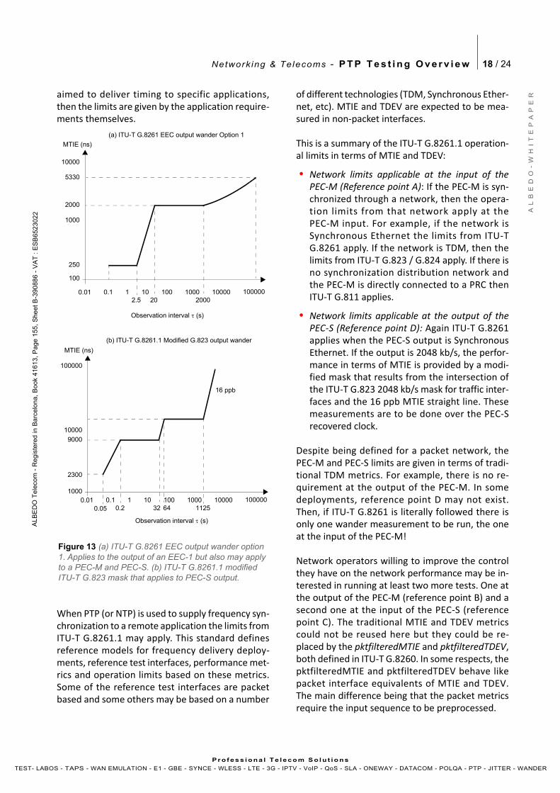
• Network limits applicable at the output of thePEC‐S (Reference point D): Again ITU‐T G.8261applies when the PEC‐S output is SynchronousEthernet. If the output is 2048 kb/s, the perfor‐mance in terms of MTIE is provided by a modi‐fied mask that results from the intersection ofthe ITU‐T G.823 2048 kb/s mask for traffic inter‐faces and the 16 ppb MTIE straight line. Thesemeasurements are to be done over the PEC‐Srecovered clock.
Despite being defined for a packet network, thePEC‐M and PEC‐S limits are given in terms of tradi‐tional TDM metrics. For example, there is no re‐quirement at the output of the PEC‐M. In somedeployments, reference point D may not exist.Then, if ITU‐T G.8261 is literally followed there isonly one wander measurement to be run, the oneat the input of the PEC‐M!
Network operators willing to improve the controlthey have on the network performance may be in‐terested in running at least two more tests. One atthe output of the PEC‐M (reference point B) and asecond one at the input of the PEC‐S (referencepoint C). The traditional MTIE and TDEV metricscould not be reused here but they could be re‐placed by the pktfilteredMTIE and pktfilteredTDEV,both defined in ITU‐T G.8260. In some respects, thepktfilteredMTIE and pktfilteredTDEV behave likepacket interface equivalents of MTIE and TDEV.The main difference being that the packet metricsrequire the input sequence to be preprocessed.
10000
Observation interval (s)
100
MTIE (ns)
10.1
1000
10 100 1000 10000 100000
5330
2000
250
2.5 20 20000.01
10000
Observation interval (s)
MTIE (ns)
10.11000
10 100 1000 10000 100000
9000
2300
0.2 32 11250.01
Figure 13 (a) ITU-T G.8261 EEC output wander option 1. Applies to the output of an EEC-1 but also may apply to a PEC-M and PEC-S. (b) ITU-T G.8261.1 modified ITU-T G.823 mask that applies to PEC-S output.
0.05 64
100000
16 ppb
(a) ITU-T G.8261 EEC output wander Option 1
(b) ITU-T G.8261.1 Modified G.823 output wander
Network ing & Telecoms - P T P T e s t i n g O v e r v i e w 19 / 24
A L
B E
D O
- W
H I
T E
P A
P E
R
AL B
ED
O T
ele
com
- R
eg
iste
r ed
in B
arc
elo
na
, B
oo
k 41
61
3, P
age
15
5,
Sh
ee
t B-3
9 08
86
- V
AT
: E
SB
652
30
2 2
Pr o f es s i ona l Te l eco m S o l u t io ns
TEST- LABOS - TAPS - WAN EMULATION - E1 - GBE - SYNCE - WLESS - LTE - 3G - IPTV - VoIP - QoS - SLA - ONEWAY - DATACOM - POLQA - PTP - JITTER - WANDER
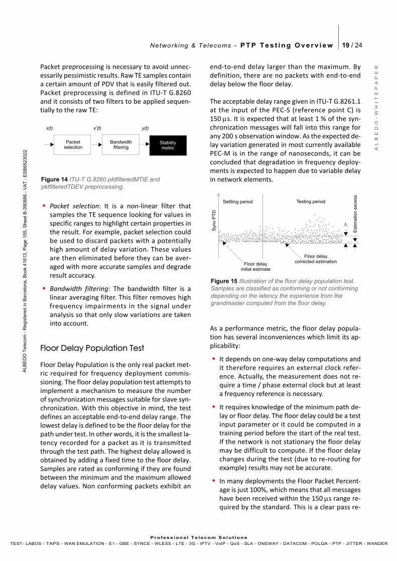
Packet preprocessing is necessary to avoid unnec‐essarily pessimistic results. Raw TE samples containa certain amount of PDV that is easily filtered out.Packet preprocessing is defined in ITU‐T G.8260and it consists of two filters to be applied sequen‐tially to the raw TE:
• Packet selection: It is a non‐linear filter thatsamples the TE sequence looking for values inspecific ranges to highlight certain properties inthe result. For example, packet selection couldbe used to discard packets with a potentiallyhigh amount of delay variation. These valuesare then eliminated before they can be aver‐aged with more accurate samples and degraderesult accuracy.
• Bandwidth filtering: The bandwidth filter is alinear averaging filter. This filter removes highfrequency impairments in the signal underanalysis so that only slow variations are takeninto account.
Floor Delay Population Test
Floor Delay Population is the only real packet met‐ric required for frequency deployment commis‐sioning. The floor delay population test attempts toimplement a mechanism to measure the numberof synchronization messages suitable for slave syn‐chronization. With this objective in mind, the testdefines an acceptable end‐to‐end delay range. Thelowest delay is defined to be the floor delay for thepath under test. In other words, it is the smallest la‐tency recorded for a packet as it is transmittedthrough the test path. The highest delay allowed isobtained by adding a fixed time to the floor delay.Samples are rated as conforming if they are foundbetween the minimum and the maximum alloweddelay values. Non conforming packets exhibit an
end‐to‐end delay larger than the maximum. Bydefinition, there are no packets with end‐to‐enddelay below the floor delay.
The acceptable delay range given in ITU‐T G.8261.1at the input of the PEC‐S (reference point C) is150 s. It is expected that at least 1 % of the syn‐chronization messages will fall into this range forany 200 s observation window. As the expected de‐lay variation generated in most currently availablePEC‐M is in the range of nanoseconds, it can beconcluded that degradation in frequency deploy‐ments is expected to happen due to variable delayin network elements.
As a performance metric, the floor delay popula‐tion has several inconveniences which limit its ap‐plicability:
• It depends on one‐way delay computations andit therefore requires an external clock refer‐ence. Actually, the measurement does not re‐quire a time / phase external clock but at leasta frequency reference is necessary.
• It requires knowledge of the minimum path de‐lay or floor delay. The floor delay could be a testinput parameter or it could be computed in atraining period before the start of the real test.If the network is not stationary the floor delaymay be difficult to compute. If the floor delaychanges during the test (due to re‐routing forexample) results may not be accurate.
• In many deployments the Floor Packet Percent‐age is just 100%, which means that all messageshave been received within the 150 s range re‐quired by the standard. This is a clear pass re‐
Figure 14 ITU-T G.8260 pktfilteredMTIE and pktfilteredTDEV preprocessing.
Stabilitymetric
BandwidthPacketselection
x(t)
filtering
x’(t) y(t)
Syn
cP
TD
Settling period Testing period
Floor delayinitial estimate
Floor delaycorrected estimation
Est
imat
ion
exce
ss
Figure 15 Illustration of the floor delay population test. Samples are classified as conforming or not conforming depending on the latency the experience from the grandmaster computed from the floor delay.
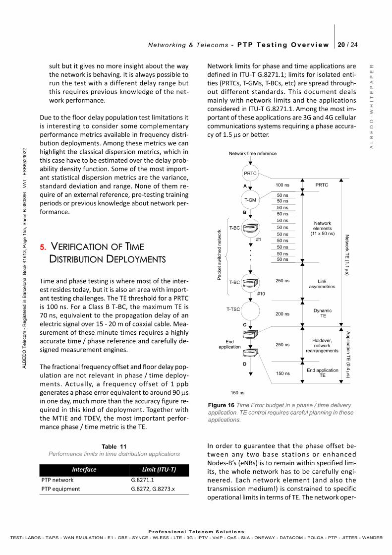
Network ing & Telecoms - P T P T e s t i n g O v e r v i e w 20 / 24
A L
B E
D O
- W
H I
T E
P A
P E
R
AL B
ED
O T
ele
com
- R
eg
iste
r ed
in B
arc
elo
na
, B
oo
k 41
6 13,
Pa
ge 1
55
, S
he
et B
-39 0
88
6 -
VA
T :
ES
B65
23
02 2
Pr o f es s i ona l Te l eco m S o l u t io ns
TEST- LABOS - TAPS - WAN EMULATION - E1 - GBE - SYNCE - WLESS - LTE - 3G - IPTV - VoIP - QoS - SLA - ONEWAY - DATACOM - POLQA - PTP - JITTER - WANDER
sult but it gives no more insight about the waythe network is behaving. It is always possible torun the test with a different delay range butthis requires previous knowledge of the net‐work performance.
Due to the floor delay population test limitations itis interesting to consider some complementaryperformance metrics available in frequency distri‐bution deployments. Among these metrics we canhighlight the classical dispersion metrics, which inthis case have to be estimated over the delay prob‐ability density function. Some of the most import‐ant statistical dispersion metrics are the variance,standard deviation and range. None of them re‐quire of an external reference, pre‐testing trainingperiods or previous knowledge about network per‐formance.
5. VERIFICATION OF TIMEDISTRIBUTION DEPLOYMENTS
Time and phase testing is where most of the inter‐est resides today, but it is also an area with import‐ant testing challenges. The TE threshold for a PRTCis 100 ns. For a Class B T‐BC, the maximum TE is70 ns, equivalent to the propagation delay of anelectric signal over 15 ‐ 20 m of coaxial cable. Mea‐surement of these minute times requires a highlyaccurate time / phase reference and carefully de‐signed measurement engines.
The fractional frequency offset and floor delay pop‐ulation are not relevant in phase / time deploy‐ments. Actually, a frequency offset of 1 ppbgenerates a phase error equivalent to around 90 sin one day, much more than the accuracy figure re‐quired in this kind of deployment. Together withthe MTIE and TDEV, the most important perfor‐mance phase / time metric is the TE.
Network limits for phase and time applications aredefined in ITU‐T G.8271.1; limits for isolated enti‐ties (PRTCs, T‐GMs, T‐BCs, etc) are spread through‐out different standards. This document dealsmainly with network limits and the applicationsconsidered in ITU‐T G.8271.1. Among the most im‐portant of these applications are 3G and 4G cellularcommunications systems requiring a phase accura‐cy of 1.5 s or better.
In order to guarantee that the phase offset be‐tween any two base stat ions or enhancedNodes‐B’s (eNBs) is to remain within specified lim‐its, the whole network has to be carefully engi‐neered. Each network element (and also thetransmission medium!) is constrained to specificoperational limits in terms of TE. The network oper‐
Table 11Performance limits in time distribution applications
Interface Limit (ITU‐T)
PTP network G.8271.1
PTP equipment G.8272, G.8273.x
Figure 16 Time Error budget in a phase / time delivery application. TE control requires careful planning in these applications.
T-BC
PRTC
T-GM
Network time reference
A
B
D
T-BC
C
T-TSC
Pack
et s
witc
hed
netw
ork
50 ns50 ns
50 ns50 ns
50 ns
50 ns
50 ns50 ns
50 ns
50 ns50 ns
250 ns
200 ns
250 ns
150 ns
100 ns
Netw
ork T
E (1
.1 s)
Application
TE
(0.4
s)
150 ns
PRTC
Networkelements
(11 x 50 ns)
Linkasymmetries
Dynamic TE
Holdover,network
rearrangements
End applicationTE
Endapplication
#1
#10
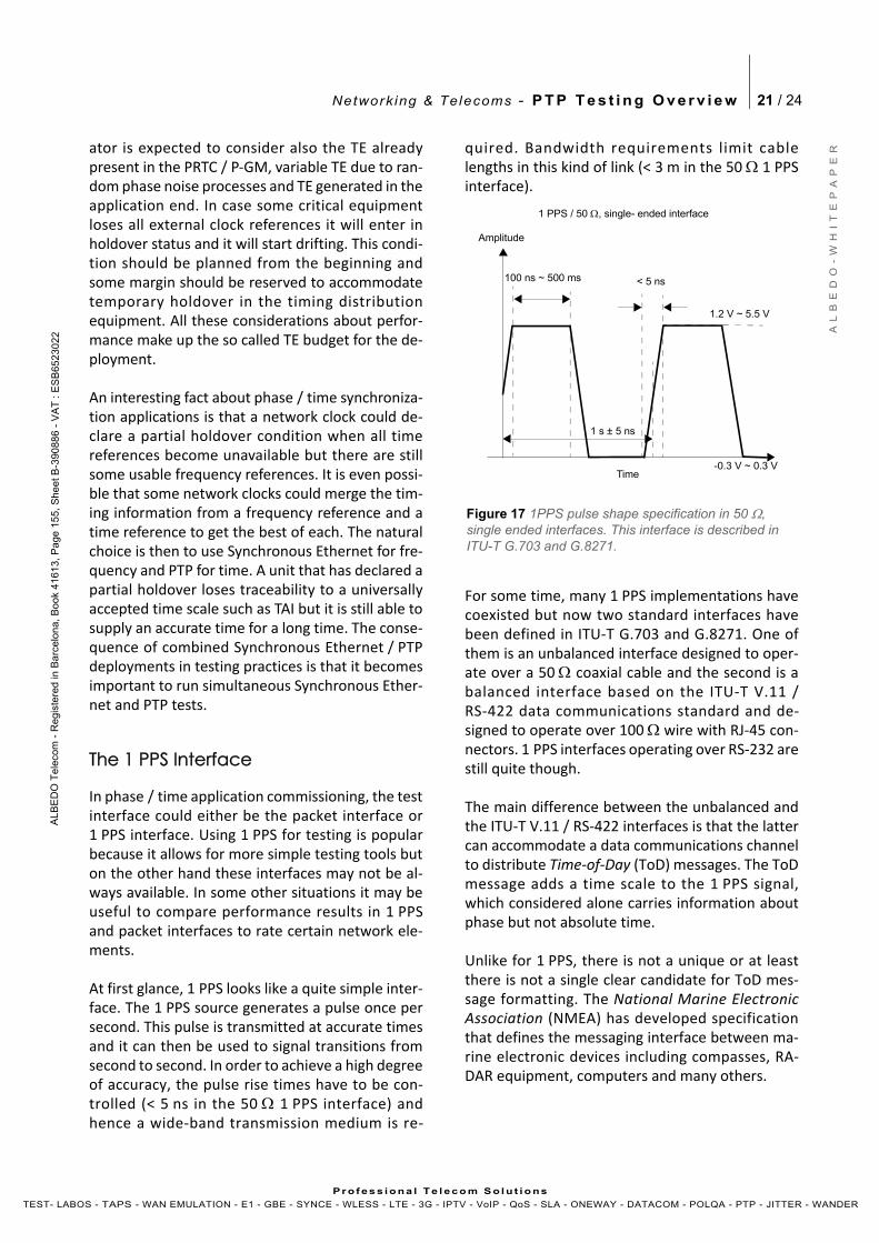
Network ing & Telecoms - P T P T e s t i n g O v e r v i e w 21 / 24
A L
B E
D O
- W
H I
T E
P A
P E
R
AL B
ED
O T
ele
com
- R
eg
iste
r ed
in B
arc
elo
na
, B
oo
k 41
6 13,
Pa
ge 1
55
, S
he
et B
-39 0
88
6 -
VA
T :
ES
B65
23
02 2
Pr o f es s i ona l Te l eco m S o l u t io ns
TEST- LABOS - TAPS - WAN EMULATION - E1 - GBE - SYNCE - WLESS - LTE - 3G - IPTV - VoIP - QoS - SLA - ONEWAY - DATACOM - POLQA - PTP - JITTER - WANDER
ator is expected to consider also the TE alreadypresent in the PRTC / P‐GM, variable TE due to ran‐dom phase noise processes and TE generated in theapplication end. In case some critical equipmentloses all external clock references it will enter inholdover status and it will start drifting. This condi‐tion should be planned from the beginning andsome margin should be reserved to accommodatetemporary holdover in the timing distributionequipment. All these considerations about perfor‐mance make up the so called TE budget for the de‐ployment.
An interesting fact about phase / time synchroniza‐tion applications is that a network clock could de‐clare a partial holdover condition when all timereferences become unavailable but there are stillsome usable frequency references. It is even possi‐ble that some network clocks could merge the tim‐ing information from a frequency reference and atime reference to get the best of each. The naturalchoice is then to use Synchronous Ethernet for fre‐quency and PTP for time. A unit that has declared apartial holdover loses traceability to a universallyaccepted time scale such as TAI but it is still able tosupply an accurate time for a long time. The conse‐quence of combined Synchronous Ethernet / PTPdeployments in testing practices is that it becomesimportant to run simultaneous Synchronous Ether‐net and PTP tests.
The 1 PPS Interface
In phase / time application commissioning, the testinterface could either be the packet interface or1 PPS interface. Using 1 PPS for testing is popularbecause it allows for more simple testing tools buton the other hand these interfaces may not be al‐ways available. In some other situations it may beuseful to compare performance results in 1 PPSand packet interfaces to rate certain network ele‐ments.
At first glance, 1 PPS looks like a quite simple inter‐face. The 1 PPS source generates a pulse once persecond. This pulse is transmitted at accurate timesand it can then be used to signal transitions fromsecond to second. In order to achieve a high degreeof accuracy, the pulse rise times have to be con‐trolled (< 5 ns in the 50 1 PPS interface) andhence a wide‐band transmission medium is re‐
quired. Bandwidth requirements limit cablelengths in this kind of link (< 3 m in the 50 1 PPSinterface).
For some time, many 1 PPS implementations havecoexisted but now two standard interfaces havebeen defined in ITU‐T G.703 and G.8271. One ofthem is an unbalanced interface designed to oper‐ate over a 50 coaxial cable and the second is abalanced interface based on the ITU‐T V.11 /RS‐422 data communications standard and de‐signed to operate over 100 wire with RJ‐45 con‐nectors. 1 PPS interfaces operating over RS‐232 arestill quite though.
The main difference between the unbalanced andthe ITU‐T V.11 / RS‐422 interfaces is that the lattercan accommodate a data communications channelto distribute Time‐of‐Day (ToD) messages. The ToDmessage adds a time scale to the 1 PPS signal,which considered alone carries information aboutphase but not absolute time.
Unlike for 1 PPS, there is not a unique or at leastthere is not a single clear candidate for ToD mes‐sage formatting. The National Marine ElectronicAssociation (NMEA) has developed specificationthat defines the messaging interface between ma‐rine electronic devices including compasses, RA‐DAR equipment, computers and many others.
Figure 17 1PPS pulse shape specification in 50 , single ended interfaces. This interface is described in ITU-T G.703 and G.8271.
1 PPS / 50 , single- ended interface
Time
Amplitude
1 s ± 5 ns
100 ns ~ 500 ms < 5 ns
1.2 V ~ 5.5 V
-0.3 V ~ 0.3 V
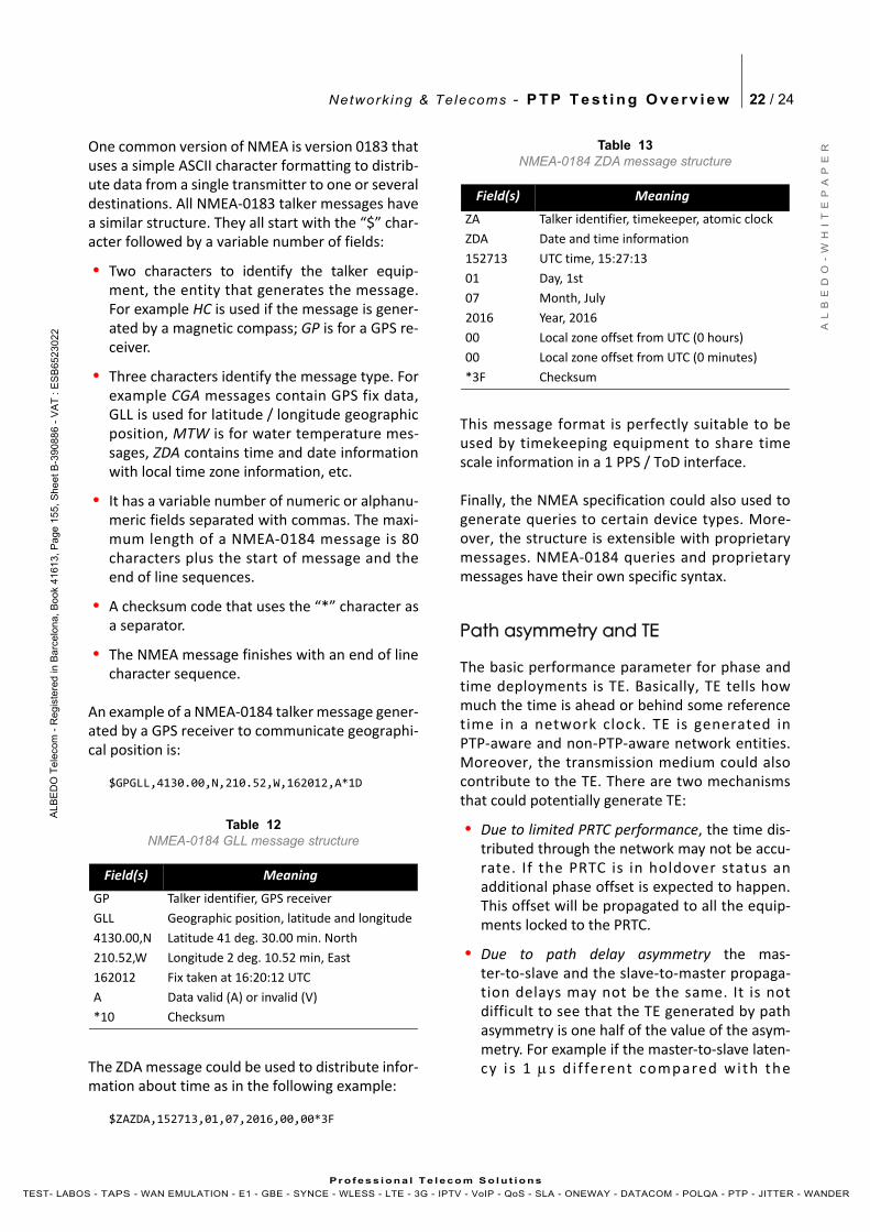
Network ing & Telecoms - P T P T e s t i n g O v e r v i e w 22 / 24
A L
B E
D O
- W
H I
T E
P A
P E
R
AL B
ED
O T
ele
com
- R
eg
iste
r ed
in B
arc
elo
na
, B
oo
k 41
6 13,
Pa
ge 1
55
, S
he
et B
-39 0
88
6 -
VA
T :
ES
B65
23
02 2
Pr o f es s i ona l Te l eco m S o l u t io ns
TEST- LABOS - TAPS - WAN EMULATION - E1 - GBE - SYNCE - WLESS - LTE - 3G - IPTV - VoIP - QoS - SLA - ONEWAY - DATACOM - POLQA - PTP - JITTER - WANDER
One common version of NMEA is version 0183 thatuses a simple ASCII character formatting to distrib‐ute data from a single transmitter to one or severaldestinations. All NMEA‐0183 talker messages havea similar structure. They all start with the “$” char‐acter followed by a variable number of fields:
• Two characters to identify the talker equip‐ment, the entity that generates the message.For example HC is used if the message is gener‐ated by a magnetic compass; GP is for a GPS re‐ceiver.
• Three characters identify the message type. Forexample CGA messages contain GPS fix data,GLL is used for latitude / longitude geographicposition, MTW is for water temperature mes‐sages, ZDA contains time and date informationwith local time zone information, etc.
• It has a variable number of numeric or alphanu‐meric fields separated with commas. The maxi‐mum length of a NMEA‐0184 message is 80characters plus the start of message and theend of line sequences.
• A checksum code that uses the “*” character asa separator.
• The NMEA message finishes with an end of linecharacter sequence.
An example of a NMEA‐0184 talker message gener‐ated by a GPS receiver to communicate geographi‐cal position is:
$GPGLL,4130.00,N,210.52,W,162012,A*1D
The ZDA message could be used to distribute infor‐mation about time as in the following example:
$ZAZDA,152713,01,07,2016,00,00*3F
This message format is perfectly suitable to beused by timekeeping equipment to share timescale information in a 1 PPS / ToD interface.
Finally, the NMEA specification could also used togenerate queries to certain device types. More‐over, the structure is extensible with proprietarymessages. NMEA‐0184 queries and proprietarymessages have their own specific syntax.
Path asymmetry and TE
The basic performance parameter for phase andtime deployments is TE. Basically, TE tells howmuch the time is ahead or behind some referencetime in a network clock. TE is generated inPTP‐aware and non‐PTP‐aware network entities.Moreover, the transmission medium could alsocontribute to the TE. There are two mechanismsthat could potentially generate TE:
• Due to limited PRTC performance, the time dis‐tributed through the network may not be accu‐rate. If the PRTC is in holdover status anadditional phase offset is expected to happen.This offset will be propagated to all the equip‐ments locked to the PRTC.
• Due to path delay asymmetry the mas‐ter‐to‐slave and the slave‐to‐master propaga‐tion delays may not be the same. It is notdifficult to see that the TE generated by pathasymmetry is one half of the value of the asym‐metry. For example if the master‐to‐slave laten‐cy i s 1 s d i f ferent compared with the
Table 12NMEA-0184 GLL message structure
Field(s) Meaning
GP Talker identifier, GPS receiver
GLL Geographic position, latitude and longitude
4130.00,N Latitude 41 deg. 30.00 min. North
210.52,W Longitude 2 deg. 10.52 min, East
162012 Fix taken at 16:20:12 UTC
A Data valid (A) or invalid (V)
*10 Checksum
Table 13NMEA-0184 ZDA message structure
Field(s) Meaning
ZA Talker identifier, timekeeper, atomic clock
ZDA Date and time information
152713 UTC time, 15:27:13
01 Day, 1st
07 Month, July
2016 Year, 2016
00 Local zone offset from UTC (0 hours)
00 Local zone offset from UTC (0 minutes)
*3F Checksum
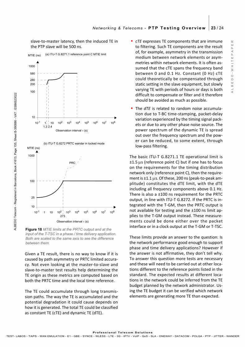
Network ing & Telecoms - P T P T e s t i n g O v e r v i e w 23 / 24
A L
B E
D O
- W
H I
T E
P A
P E
R
AL B
ED
O T
ele
com
- R
eg
iste
r ed
in B
arc
elo
na
, B
oo
k 41
6 13,
Pa
ge 1
55
, S
he
et B
-39 0
88
6 -
VA
T :
ES
B65
23
02 2
Pr o f es s i ona l Te l eco m S o l u t io ns
TEST- LABOS - TAPS - WAN EMULATION - E1 - GBE - SYNCE - WLESS - LTE - 3G - IPTV - VoIP - QoS - SLA - ONEWAY - DATACOM - POLQA - PTP - JITTER - WANDER
slave‐to‐master latency, then the induced TE inthe PTP slave will be 500 ns.
Given a TE result, there is no way to know if it iscaused by path asymmetry or PRTC limited accura‐cy. Not even looking at the master‐to‐slave andslave‐to‐master test results help determining theTE origin as these metrics are computed based onboth the PRTC time and the local time reference.
The TE could accumulate through long transmis‐sion paths. The way the TE is accumulated and thepotential degradation it could cause depends onhow it is generated. The total TE could be classifiedas constant TE (cTE) and dynamic TE (dTE).
• cTE expresses TE components that are immuneto filtering. Such TE components are the resultof, for example, asymmetry in the transmissionmedium between network elements or asym‐metries within network elements. It is often as‐sumed that the cTE spans the frequency bandbetween 0 and 0.1 Hz. Constant (0 Hz) cTEcould theoretically be compensated throughstatic setting in the slave equipment, but slowlyvarying TE with periods of hours or days is bothdifficult to compensate or filter and it thereforeshould be avoided as much as possible.
• The dTE is related to random noise accumula‐tion due to T‐BC time‐stamping, packet‐delayvariation experienced by the timing signal pack‐ets or due to any other phase noise source. Thepower spectrum of the dynamic TE is spreadout over the frequency spectrum and the pow‐er can be reduced, to some extent, throughlow‐pass filtering.
The basic ITU‐T G.8271.1 TE operational limit is±1.5 s (reference point C) but if one has to focuson the requirements for the timing distributionnetwork only (reference point C), then the require‐ment is ±1.1 s. Of these, 200 ns (peak‐to‐peak am‐plitude) constitutes the dTE limit, with the dTEincluding all frequency components above 0.1 Hz.There is also a ±100 ns requirement for the PRTCoutput, in line with ITU‐T G.8272. If the PRTC is in‐tegrated with the T‐GM, then the PRTC output isnot available for testing and the ±100 ns limit ap‐plies to the T‐GM output instead. These measure‐ments could be done either over the packetinterface or in a clock output at the T‐GM or T‐TSC.
These limits provide an answer to the question: Isthe network performance good enough to supportphase and time delivery applications? However ifthe answer is not affirmative, they don’t tell why.To answer this question more tests are necessaryand these will need to be carried out at other loca‐tions different to the reference points listed in thestandard. The expected results at different loca‐tions in the network could be inferred from the TEbudget planned by the network administrator. Us‐ing the TE budget it can be verified which networkelements are generating more TE than expected.
103 104
273
1000
10
MTIE (ns)
101
100
102 103 104 105 106
1.310-1
(a) ITU-T G.8271.1 reference point C MTIE limit
107 108
580
1000
10
MTIE (ns)
101
100
102 105 10610-1
(b) ITU-T G.8272 PRTC wander in locked mode
107 108
25
2.4
Observation interval (s)
280
200
Figure 18 MTIE limits at the PRTC output and at the input of the T-TSC in a phase / time delivery application. Both are scaled to the same axis to see the difference between them.
Observation interval (s)
PRC
Network ing & Telecoms - P T P T e s t i n g O v e r v i e w 24 / 24
A L
B E
D O
- W
H I
T E
P A
P E
R
AL B
ED
O T
ele
com
- R
eg
iste
r ed
in B
arc
elo
na
, B
oo
k 41
6 13,
Pa
ge 1
55
, S
he
et B
-39 0
88
6 -
VA
T :
ES
B65
23
02 2
Pr o f es s i ona l Te l eco m S o l u t io ns
TEST- LABOS - TAPS - WAN EMULATION - E1 - GBE - SYNCE - WLESS - LTE - 3G - IPTV - VoIP - QoS - SLA - ONEWAY - DATACOM - POLQA - PTP - JITTER - WANDER
MTIE and TDEV
MTIE and TDEV are still important performancemetrics in phase / time distribution deploymentsbut the way they are used is slightly different inphase deployments. The TDEV and specially theMTIE could be used to measure slowly varying TE.In the same way that a constant frequency offsetrequirement could be added to the MTIE maskthrough a straight line with specific slope, a phaserequirement could be added through an horizontalline with the phase offset requirement being thedistance of the line to the horizontal axis.
This approach is used by standards ITU‐T G.8271.1and G.8272, among others. The MTIE at the PRTC isup to 100 ns, the T‐TSC MTIE contains componentsup to 580 ns. In a T‐BC, the MTIE is 40 ns when theinput is considered free of any impairment.
6. BIBLIOGRAPHY
[1] IEEE Std. 1588‐2008, “IEEE Standard for a Precision Clock Synchronization Protocol for Networked Measurement and Control Systems”, 24 July 2008.
[2] ITU‐T G.703, “Physical/electrical characteristics of hierarchical digital interfaces”, November 2001.
[3] ITU‐T G.781, “Synchronization layer functions”, September 2008.
[4] ITU‐T G.810, “Definitions and terminology for syn‐chronization networks”, August 1996.
[5] ITU‐T G.811, “Timing characteristics of primary reference clocks”, September 1997.
[6] ITU‐T G.812, “Timing requirements of slave clocks suitable for use as node clocks in synchronization networks”, June 2004.
[7] ITU‐T G.813, “Timing characteristics of SDH equip‐ment slave clocks (SEC)”, March 2003.
[8] ITU‐T G.823, “The control of jitter and wander within digital networks which are based on the 2048 kbit/s hierarchy”, March 2000.
[9] ITU‐T G.824, “The control of jitter and wander within digital networks which are based on the 1544 kbit/s hierarchy”, March 2000.
[10] ITU‐T G.8260, “Definitions and terminology for synchronization in packet networks”, February 2012.
[11] ITU‐T G.8261 / Y.1361, “Timing and synchroniza‐tion aspects in packet networks”, August 2013.
[12] ITU‐T G.8261.1 / Y.1361.1, “Packet delay variation network limits applicable to packet‐based meth‐ods (Frequency synchronization)”, February 2012.
[13] ITU‐T G.8262 / Y.1362, “Timing characteristics of synchronous Ethernet equipment slave clock”, Jan‐uary 2015.
[14] ITU‐T G.8263 / Y.1363, “Timing characteristics of packet‐based equipment clocks”, February 2012.
[15] ITU‐T G.8264 / Y.1364, “Distribution of timing information through packet networks”, May 2014.
[16] ITU‐T G.8265 / Y.1365, “Architecture and require‐ments for packet‐based frequency delivery”, November 2010.
[17] ITU‐T G.8261.1 / Y.1365.1, “Precision time proto‐col telecom profile for frequency synchronization”, July 2014.
[18] ITU‐T G.8271 / Y.1366, “Time and phase synchro‐nization aspects of packet networks”, February 2012.
[19] ITU‐T G.8271.1 / Y.1366.1, “Network limits for time synchronization in packet networks”, August 2013.
[20] ITU‐T G.8272 / Y.1367, “Timing characteristics of primary reference time clocks”, January 2015.
[21] ITU‐T G.8273 / Y.1368, “Framework of phase and time clocks”, August 2013.
[22] ITU‐T G.8273.2 / Y.1368.2, “Timing characteristics of telecom boundary clocks and telecom time slave clocks”, April 2014.
[23] ITU‐T G.8275 / Y.1369, “Architecture and require‐ments for packet‐based time and phase distribu‐tion”, November 2013.
[24] ITU‐T G.8275.1 / Y.13691, “Precision time protocol telecom profile for phase/time synchronization with full timing support from the network”, July 2014.
[25] ITU‐T O.174, “Jitter and wander measuring equip‐ment for digital systems which are based on syn‐chronous Ethernet technology”, November 2009.