Embed Size (px)
Citation preview

Motorola B2B Collateral Branding UK Manual Cover insert A4 Text Field Template (02/10/07)
Sign o� ........................................ date ................ Sht no 1 of 1 ag-UK-Manual Cover insert A4 Text Fields Template-00001-v02-ai-sw
Customer Documetation UK 2007
PTP-SYNC
phn-1613_004v000
Installation Guide
April 2010
Using this template follow these procedures.
1. Complete all the text fields using provided spreadsheet and specification information2. Save file using appropriate naming title/convention in PDF format
© 2010 Motorola, Inc. All Rights Reserved.
4Gon www.4Gon.co.uk [email protected] Tel: +44 (0)1245 808195 Fax: +44 (0)1245 808299

phn-1613_004v000 (Apr 2010)
Accuracy
While reasonable efforts have been made to assure the accuracy of this document, Motorola, Inc. assumes no liability resulting from any inaccuracies or omissions in this document, or from use of the information obtained herein. Motorola, Inc. reserves the right to make changes to any products described herein to improve reliability, function, or design, and reserves the right to revise this document and to make changes from time to time in content hereof with no obligation to notify any person of revisions or changes. Motorola, Inc. does not assume any liability arising out of the application or use of any product, software, or circuit described herein; neither does it convey license under its patent rights or the rights of others. It is possible that this publication may contain references to, or information about Motorola products (machines and programs), programming, or services that are not announced in your country. Such references or information must not be construed to mean that Motorola intends to announce such Motorola products, programming, or services in your country.
Copyrights
This document, Motorola products, and 3rd Party Software products described in this document may include or describe copyrighted Motorola and other 3rd Party supplied computer programs stored in semiconductor memories or other media. Laws in the United States and other countries preserve for Motorola, its licensors, and other 3rd Party supplied software certain exclusive rights for copyrighted material, including the exclusive right to copy, reproduce in any form, distribute and make derivative works of the copyrighted material. Accordingly, any copyrighted material of Motorola, its licensors, or the 3rd Party software supplied material contained in the Motorola products described in this document may not be copied, reproduced, reverse engineered, distributed, merged or modified in any manner without the express written permission of Motorola. Furthermore, the purchase of Motorola products shall not be deemed to grant either directly or by implication, estoppel, or otherwise, any license under the copyrights, patents or patent applications of Motorola or other 3rd Party supplied software, except for the normal non-exclusive, royalty free license to use that arises by operation of law in the sale of a product.
Restrictions
Software and documentation are copyrighted materials. Making unauthorized copies is prohibited by law. No part of the software or documentation may be reproduced, transmitted, transcribed, stored in a retrieval system, or translated into any language or computer language, in any form or by any means, without prior written permission of Motorola, Inc.
License Agreements
The software described in this document is the property of Motorola, Inc and its licensors. It is furnished by express license agreement only and may be used only in accordance with the terms of such an agreement.
High Risk Materials
Components, units, or 3rd Party products used in the product described herein are NOT fault-tolerant and are NOT designed, manufactured, or intended for use as on-line control equipment in the following hazardous environments requiring fail-safe controls: the operation of Nuclear Facilities, Aircraft Navigation or Aircraft Communication Systems, Air Traffic Control, Life Support, or Weapons Systems (High Risk Activities). Motorola and its supplier(s) specifically disclaim any expressed or implied warranty of fitness for such High Risk Activities.
Trademarks
MOTOROLA and the Stylized M Logo are registered in the US Patent & Trademark Office. All other product or service names are the property of their respective owners.
4Gon www.4Gon.co.uk [email protected] Tel: +44 (0)1245 808195 Fax: +44 (0)1245 808299

PTP-SYNC Installation Guide
i
Important safety information
WARNING
To prevent loss of life or physical injury, observe the safety guidelines in this section.
Power lines Exercise extreme care when installing antennas near power lines.
Working at heights Exercise extreme care when working at heights.
Grounding PTP-SYNC In order to meet the safety requirements for deployment in Australia and New Zealand (AS/NZS 60950-1), the PTP-SYNC unit, if deployed, must be grounded to a Protective Ground in accordance with Local Electrical Regulations.
Powering down before servicing Always power down and unplug the equipment before servicing.
Primary disconnect device The main power supply is the primary disconnect device.
External cables Safety may be compromised if outdoor rated cables are not used for connections that will be exposed to the weather.
4Gon www.4Gon.co.uk [email protected] Tel: +44 (0)1245 808195 Fax: +44 (0)1245 808299

Important safety information PTP-SYNC Installation Guide
ii
4Gon www.4Gon.co.uk [email protected] Tel: +44 (0)1245 808195 Fax: +44 (0)1245 808299
PTP-SYNC Installation Guide
iii
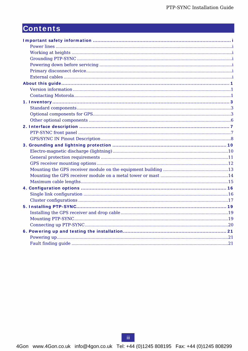
Contents Important safety information ............................................................................................ i
Power lines .....................................................................................................................................i Working at heights .........................................................................................................................i Grounding PTP-SYNC .....................................................................................................................i Powering down before servicing ....................................................................................................i Primary disconnect device..............................................................................................................i External cables ...............................................................................................................................i
About this guide................................................................................................................ 1 Version information .......................................................................................................................1 Contacting Motorola......................................................................................................................1
1. Inventory...................................................................................................................... 3 Standard components....................................................................................................................3 Optional components for GPS........................................................................................................3 Other optional components ...........................................................................................................6
2. Interface description .................................................................................................... 7 PTP-SYNC front panel ...................................................................................................................7 GPS/SYNC IN Pinout Description..................................................................................................8
3. Grounding and lightning protection ............................................................................ 10 Electro-magnetic discharge (lightning) .......................................................................................10 General protection requirements ................................................................................................11 GPS receiver mounting options ...................................................................................................12 Mounting the GPS receiver module on the equipment building .................................................13 Mounting the GPS receiver module on a metal tower or mast ...................................................14 Maximum cable lengths...............................................................................................................15
4. Configuration options ................................................................................................. 16 Single link configuration .............................................................................................................16 Cluster configurations .................................................................................................................17
5. Installing PTP-SYNC.................................................................................................... 19 Installing the GPS receiver and drop cable.................................................................................19 Mounting PTP-SYNC....................................................................................................................19 Connecting up PTP-SYNC............................................................................................................20
6. Powering up and testing the installation..................................................................... 21 Powering up.................................................................................................................................21 Fault finding guide ......................................................................................................................21
4Gon www.4Gon.co.uk [email protected] Tel: +44 (0)1245 808195 Fax: +44 (0)1245 808299

Contents PTP-SYNC Installation Guide
iv
4Gon www.4Gon.co.uk [email protected] Tel: +44 (0)1245 808195 Fax: +44 (0)1245 808299
PTP-SYNC Installation Guide
1
About this guide
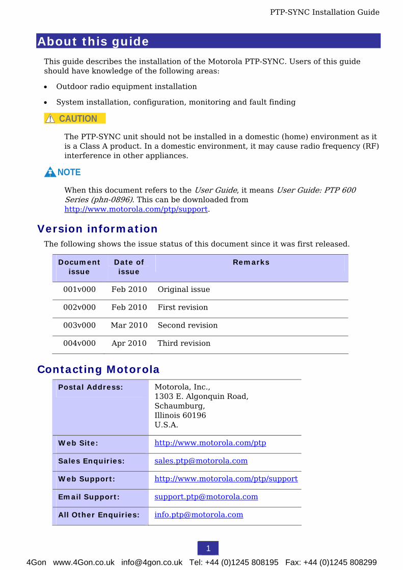
This guide describes the installation of the Motorola PTP-SYNC. Users of this guide should have knowledge of the following areas:
• Outdoor radio equipment installation
• System installation, configuration, monitoring and fault finding
CAUTION
The PTP-SYNC unit should not be installed in a domestic (home) environment as it is a Class A product. In a domestic environment, it may cause radio frequency (RF) interference in other appliances.
NOTE
When this document refers to the User Guide, it means User Guide: PTP 600 Series (phn-0896). This can be downloaded from http://www.motorola.com/ptp/support.
Version information The following shows the issue status of this document since it was first released.
Document issue
Date of issue
Remarks
001v000 Feb 2010 Original issue
002v000 Feb 2010 First revision
003v000 Mar 2010 Second revision
004v000 Apr 2010 Third revision
Contacting Motorola
Postal Address: Motorola, Inc., 1303 E. Algonquin Road, Schaumburg, Illinois 60196 U.S.A.
Web Site: http://www.motorola.com/ptp
Sales Enquiries: [email protected]
Web Support: http://www.motorola.com/ptp/support
Email Support: [email protected]
All Other Enquiries: [email protected]
4Gon www.4Gon.co.uk [email protected] Tel: +44 (0)1245 808195 Fax: +44 (0)1245 808299

About this guide PTP-SYNC Installation Guide
2
Technical support telephone numbers
Region and country
Telephone Region and country
Telephone
North America: Latin and Central America:
USA and Canada 866-961-9288 Argentina 0800-666-2789
Europe, Middle East and Africa: Brazil 0800-891-4360
Denmark 043682114 Chile 800-225-288
France 0157323434 Columbia 01-800-912-0557
Germany 06950070204 Mexico 001-800-942-7721
Italy 0291483230 Peru 0800-70-086
Lithuania 800 030 828 All other countries +420 533 336 946
Netherlands 0202061404 Asia, Pacific and China:
Norway 24159815 Australia 800 457 439
Portugal 0217616160 Singapore 64 155 110
Spain 912754787 All other countries +420 533 336 946
Russia 810 800 228 41044
Saudi Arabia 800 844 5345
South Africa 0800981900
United Kingdom 0203 0277499
All other countries +44 203 0277499
4Gon www.4Gon.co.uk [email protected] Tel: +44 (0)1245 808195 Fax: +44 (0)1245 808299

PTP-SYNC Installation Guide
3
1. Inventory
Standard components
PTP-SYNC kit
Part number WB3665.
The PTP-SYNC kit (Figure 1) contains the following items:
• 1 x PTP-SYNC unit
• 1 x M4 pan screw
• 2 x M4 washers
• 2 x M3 (6mm) torx drive screws
• 1 x lug for unit ground (cable not supplied)
Figure 1 PTP-SYNC kit
Indoor cable
The cable used for indoor connections, for example from the PTP-SYNC to the PIDU Plus, can be any standard screened or unscreened CAT5e cable. This must be purchased separately, as it is not supplied in the PTP-SYNC kit.
Optional components for GPS If the PTP-SYNC configuration requires GPS as the timing reference source, then the following additional components are required: GPS receiver, outdoor drop cable, connectors, glands, cable grounding kit and Lightning Protection Unit (LPU) end kit. These components must be purchased separately.
4Gon www.4Gon.co.uk [email protected] Tel: +44 (0)1245 808195 Fax: +44 (0)1245 808299

1. Inventory PTP-SYNC Installation Guide
4
GPS receiver
The Trimble Acutime™ Gold GPS receiver is a suitable timing reference source for PTP-SYNC.
Part number STLN6594.
Outdoor drop cable
This is only required for GPS configurations.
Always use Cat5e cable that is gel-filled and shielded with copper-plated steel. This is the only type of outdoor drop cable supported in this application. A suitable make is Superior Essex, with part numbers as specified in Table 1.
CAUTION
The drop cable must be Cat5e cable that is gel-filled and shielded with copper-plated steel. Alternative types of drop cable are not supported by Motorola.
Table 1 Superior Essex cable - available lengths and part numbers
Length (on plywood reel) Part number
1000 ft BBDGe 04-001-55
2500 ft BBDGe 04-002-55
5000 ft BBDGe 04-003-55
Cut to length BBDGe 04-601-55
Outdoor connectors and glands
These are only required for GPS configurations.
The recommended connectors and glands to be used for connecting the supported drop cable to the LPU are specified in Table 2.
Table 2 Recommended outdoor connectors for ODU and LPU
Item Manufacturer Part number
Connector Tyco (AMP) 5-569278
Crimp tool Tyco (AMP) 2-231652
Die set Tyco (AMP) 1-8534400-0
Gland Motorola WB1811
NOTE
The connector, crimp toll and die set listed in Table 2 are specific to Superior Essex cable. They may not work with other makes of cable.
4Gon www.4Gon.co.uk [email protected] Tel: +44 (0)1245 808195 Fax: +44 (0)1245 808299

1. Inventory PTP-SYNC Installation Guide
5
The recommended connectors and glands to be used for connecting the supported drop cable to the Trimble GPS receiver are specified in Table 3.
Table 3 Recommended outdoor connectors for Trimble GPS receiver
Item Manufacturer Part number
12 way circular connector Deutsch IMC26-2212X
Size 22 crimp socket Deutsch 6862-201-22278
Crimp tool Daniels Manufacturing Corp MH860
Positioner Daniels Manufacturing Corp 86-5
Insertion / extraction tool Deutsch 6757-201-2201
Adaptor Deutsch IMC2AD
Self amalgamating tape
Cable grounding kits for 1/4” and 3/8” cable
These are only required for GPS configurations.
Part number 01010419001.
The cable grounding kit (Figure 2) is for grounding the GPS receiver drop cable. One kit is required for each grounding point. The kit contains the following items:
• 1 x grounding cable with grounding 2 hole lug fitted (M10)
• 1 x self-amalgamating tape
• 1 x PVC tape
• 3 x tie wraps
• 2 x bolt, washer and nut
Figure 2 Cable grounding kit
4Gon www.4Gon.co.uk [email protected] Tel: +44 (0)1245 808195 Fax: +44 (0)1245 808299

1. Inventory PTP-SYNC Installation Guide
6
Lightning Protection Unit (LPU) end kit
This is only required for GPS configurations. Part number 2900.
CAUTION
The LPU (part number 2900) contained in the WB2978 kit must only be used on the GPS receiver cable. It must not be used on the drop cable to the PTP 600 ODU. The ODU drop cable uses LPU part number 2900B.
The LPU End Kit (Figure 3) is for protecting the connection to the GPS receiver.
Figure 3 LPU end kit
Other optional components
Rack mount installation kit
Part number WB3486. The PTP800 CMU / PTP-SYNC 19” rack mount installation kit (Figure 4) is an optional item that must be purchased separately. This kit contains the following components:
• 1 x rack bracket
• 8 x M3 screws and washers
• 1 x rack mount blank plate
• 8 x M5 nuts and washers
• 2 x rack handles
Figure 4 PTP 800 CMU / PTP-SYNC 19” rack mount installation kit
4Gon www.4Gon.co.uk [email protected] Tel: +44 (0)1245 808195 Fax: +44 (0)1245 808299
PTP-SYNC Installation Guide
7
2. Interface description
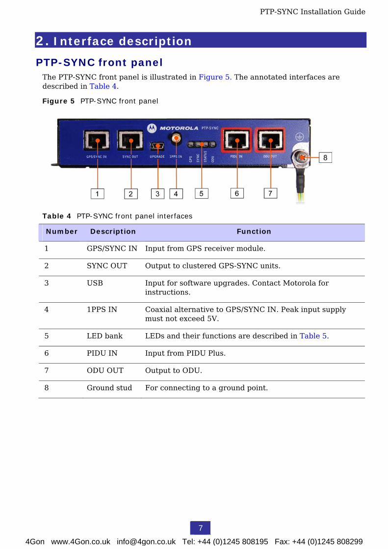
PTP-SYNC front panel The PTP-SYNC front panel is illustrated in Figure 5. The annotated interfaces are described in Table 4.
Figure 5 PTP-SYNC front panel
Table 4 PTP-SYNC front panel interfaces
Number Description Function
1 GPS/SYNC IN Input from GPS receiver module.
2 SYNC OUT Output to clustered GPS-SYNC units.
3 USB Input for software upgrades. Contact Motorola for instructions.
4 1PPS IN Coaxial alternative to GPS/SYNC IN. Peak input supply must not exceed 5V.
5 LED bank LEDs and their functions are described in Table 5.
6 PIDU IN Input from PIDU Plus.
7 ODU OUT Output to ODU.
8 Ground stud For connecting to a ground point.
4Gon www.4Gon.co.uk [email protected] Tel: +44 (0)1245 808195 Fax: +44 (0)1245 808299

2. Interface description PTP-SYNC Installation Guide
8
Table 5 PTP-SYNC indicator LEDs
Indicator Function Description
Off No GPS satellite data being received at either the GPS/SYNC IN or 1PPS IN port.
GPS
On steady or blink
GPS satellite data being received.
Off No data being received at the SYNC OUT port. SYNC
On steady or blink
Data being received at the SYNC OUT port.
Off No power.
On steady Power but no satellite lock.
STATUS
Blink Power and satellite lock at either the GPS/SYNC IN or 1PPS IN port.
Off No signal being received from the ODU. ODU
On Communication with the ODU is established.
GPS/SYNC IN Pinout Description Table 6 describes the pinouts of the GPS/SYNC IN port of the PTP-SYNC unit. Pins 3 and 6 carry the 1Hz differential input to the GPS/SYNC IN port.
Table 6 GPS/SYNC IN port pinouts
Pin no. Connector pinout signal name
Signal description
Pin 1 12VGPS 12 V output to GPS receiver module, 250 mA max
Pin 2 GND Ground
Pin 3 GPS_1PPSA 1 Hz pulse input
Pin 4 GPS_RXDA GPS receive data
Pin 5 GPS_RXDB GPS receive data
Pin 6 GPS_1PPSB 1 Hz pulse input
Pin 7 GPS_TXDA GPS transmit data
Pin 8 GPS_TXDB GPS Transmit data
4Gon www.4Gon.co.uk [email protected] Tel: +44 (0)1245 808195 Fax: +44 (0)1245 808299

2. Interface description PTP-SYNC Installation Guide
9
NOTE
The GPS_1PPS, GPS_RXD and GPS_TXD signals conform to International Telecommunication Union (ITU) recommendation V.11 (RS422).
Signal polarities
A 1 PPS timing datum is detected when GPS_1PPSA goes positive relative to GPS_1PPSB.
A serial data start bit is detected when GPS_RXDA (or GPS_TXDA) goes positive relative to GPS_RXDB (or GPS_TXDB).
RJ45 connector
Figure 6 shows how the pin numbers of the GPS/SYNC IN port correspond to the RJ45 connector color codes (with T568B color coding).
Figure 6 RJ45 pins with T568B color coding
4Gon www.4Gon.co.uk [email protected] Tel: +44 (0)1245 808195 Fax: +44 (0)1245 808299

PTP-SYNC Installation Guide
10
3. Grounding and lightning protection If a GPS receiver is the selected timing reference source, then the installation must be protected as described in this section.
WARNING
Electro-magnetic discharge (lightning) damage is not covered under warranty. The recommendations in this guide and in the user manual, when followed correctly, give the user the best protection from the harmful effects of EMD. However 100% protection is neither implied nor possible.
CAUTION
Ensure that the GPS receiver module is mounted in a position where all protection requirements can be met.
Electro-magnetic discharge (lightning)
Lightning protection zones
The ‘rolling sphere method’ is used to determine where it is safe to mount antennas or ODUs. An imaginary sphere, typically 50 meters in radius, is rolled over the structure (Figure 7). Where the sphere rests against the ground and a strike termination device (such as a finial or ground bar) all the space under the sphere is considered to be in the zone of protection (Zone B). Similarly, where the sphere rests on two finials, the space under the sphere is considered to be in the zone of protection.
Assess locations on masts, towers and buildings to determine if the location is in Zone A or Zone B:
• Zone A: In this zone a direct lightning strike is possible. Do not mount equipment in this zone.
• Zone B: In this zone, direct EMD (lightning) effects are still possible, but mounting in this zone significantly reduces the possibility of a direct strike. Mount equipment in this zone.
WARNING
Never mount equipment in Zone A. Mounting in Zone A will put equipment, structures and life at risk.
4Gon www.4Gon.co.uk [email protected] Tel: +44 (0)1245 808195 Fax: +44 (0)1245 808299

3. Grounding and lightning protection PTP-SYNC Installation Guide
11
Figure 7 Rolling sphere method to determine the lightning protection zones
General protection requirements To adequately protect a GPS receiver installation, both ground bonding and transient voltage surge suppression are required.
NOTE
Where an installation already has, or requires the use of a Master Ground Bar then the requirements of Motorola Specification R56: STANDARDS AND GUIDELINES FOR COMMUNICATION SITES (68P81089E50) take precedence over those in this guide.
4Gon www.4Gon.co.uk [email protected] Tel: +44 (0)1245 808195 Fax: +44 (0)1245 808299

3. Grounding and lightning protection PTP-SYNC Installation Guide
12
Basic requirements
The following basic protection requirements must be implemented:
• The equipment (GPS receiver for PTP-SYNC) must be in ‘Zone B’.
• A lightning protection unit (LPU) must be installed at the entry point to the building or equipment room. The use of the LPU provided in the lightning protection kit (WB2978) is strongly recommended.
• The drop cable must be bonded to the supporting structure in order to prevent lightning creating a potential between the structure and cable, which could cause arcing, resulting in damage to equipment.
• The drop cable must be grounded at the building entry point.
• The drop cable must not be laid alongside a lightning finial cable.
• All grounding cables must be minimum size 8 AWG, preferably 6 or 4 AWG.
Grounding cable requirements
When routing, fastening and connecting grounding cables, the following requirements must be implemented:
• Grounding conductors must be run as short, straight, and smoothly as possible, with the fewest possible number of bends and curves.
• Grounding cables must not be installed with drip loops.
• All bends, curves and connections must be routed towards the grounding electrode system, ground rod, or ground bar.
• Grounding conductors must be securely fastened.
• Braided grounding conductors must not be used.
• Approved bonding techniques must be used for the connection of dissimilar metals.
GPS receiver mounting options The GPS receiver for PTP-SYNC must be mounted at a location that meets both the general protection requirements and the following requirements:
• It must have an un-interrupted view of the sky.
• It must receive an adequate signal from at least four GPS satellites.
• It must be possible to protect the installation as described in General protection requirements on page 11.
The GPS receiver should be mounted on the wall of the equipment building, if there is a suitable location on the wall that can meet these requirements. Failing that, mount it on a metal tower or mast.
4Gon www.4Gon.co.uk [email protected] Tel: +44 (0)1245 808195 Fax: +44 (0)1245 808299

3. Grounding and lightning protection PTP-SYNC Installation Guide
13
Mounting the GPS receiver module on the equipment building
If mounting the GPS receiver for PTP-SYNC on the equipment building (Figure 8), select a position on the wall that meets the following requirements:
• It must be below the roof height of the equipment building or below the height of any roof-mounted equipment (such as air conditioning plant).
• It must be below the lightning terminals and finials.
• It must not project more than 600mm (24 inches) from the wall of the building.
If these requirements cannot all be met, then the module must be mounted on a metal tower or mast.
Figure 8 GPS receiver mounted on equipment building
External Ground Bar (EGB)
Rack Ground Bar (RGB)
Equipment rack
PTP-SYNC
Master Ground Bar (MGB)
Ground bus conductor
MGB grounding system
GPS Rx
To ODU/LPU
Ground cable
Screened CAT5e cable
Unscreened CAT5e cable
To PIDU Plus
Lightning Protection Unit (LPU)
4Gon www.4Gon.co.uk [email protected] Tel: +44 (0)1245 808195 Fax: +44 (0)1245 808299

3. Grounding and lightning protection PTP-SYNC Installation Guide
14
Mounting the GPS receiver module on a metal tower or mast
If mounting the GPS receiver module on a metal tower or mast (Figure 9), select a position that meets the following requirements:
• It must not be mounted any higher than is necessary to receive an adequate signal from four GPS satellites.
• It must be protected by a nearby lightning terminal or finial that projects further out from the tower than the GPS receiver module.
• It must meet all the protection requirements stated below.
Protection requirements for a mast or tower installation
If the PTP-SYNC is to be mounted on a metal tower or mast, then in addition to the general protection requirements (above), the following requirements must be observed:
• The equipment must be lower than the top of the tower or its lightning terminal and finial.
• The metal tower or mast must be correctly grounded.
• A grounding kit must be installed at the first point of contact between the drop cable and the tower, near the top.
• A grounding kit must be installed at the bottom of the tower, near the vertical to horizontal transition point. This grounding kit must be bonded to the tower or tower ground bus bar (TGB), if installed.
• If the tower is greater than 61 m (200 ft) in height, an additional grounding kit must be installed at the tower midpoint. Additional ground kits must be installed as necessary to reduce the distance between ground kits to 61 m (200 ft) or less.
• In high lightning prone geographical areas, additional ground kits should be installed at spacing between 15 to 22 m (50 to 75 ft). This is especially important on towers taller than 45 m (150 ft.).
• If a coaxial (or other) cable is already grounded to the mast or tower, the same grounding points on the mast or tower must be used for the CAT 5e cable.
4Gon www.4Gon.co.uk [email protected] Tel: +44 (0)1245 808195 Fax: +44 (0)1245 808299

3. Grounding and lightning protection PTP-SYNC Installation Guide
15
Figure 9 GPS receiver mounted on tower or mast
Maximum cable lengths The maximum permitted cable lengths for PTP-SYNC installations are:
• ODU to PTP-SYNC: 40 meters (130 ft).
• PTP-SYNC to PIDU Plus: 2 meters (6.5 ft).
• PIDU Plus to network equipment: 20 meters (65 ft).
4Gon www.4Gon.co.uk [email protected] Tel: +44 (0)1245 808195 Fax: +44 (0)1245 808299

PTP-SYNC Installation Guide
16
4. Configuration options This section describes different ways in which PTP-SYNC and its timing reference source may be configured.
Single link configuration The single link configuration (Figure 10) consists of a single PTP-SYNC with a single timing reference source (1PPS), which is normally a GPS receiver.
Figure 10 Single link configuration
IndoorsOutdoors
PIDU
LANODU
ac in Mainssupply
CustomerLAN
PTP-SYNC
GPS/SYNC IN
PIDUIN
ODUOUT
SYNC OUT
GPS receiver
LPU
Wall or mast mounted
Drop cable to ODU (via LPUs)
CAT5e indoor cable
CAT5e outdoor cable (gel-filled, shielded with copper-plated steel)
4Gon www.4Gon.co.uk [email protected] Tel: +44 (0)1245 808195 Fax: +44 (0)1245 808299

4. Configuration options PTP-SYNC Installation Guide
17
Cluster configurations The cluster configurations consist of multiple PTP-SYNC units connected in a chain. These configurations support multiple ODUs at one site. Between two and ten PTP-SYNCs may be chained in this way.
The cluster configuration with GPS (Figure 11) consists of multiple PTP-SYNC units with a single timing reference source (1PPS), which is normally a GPS receiver.
Figure 11 Cluster configuration with GPS
To nextPTP-SYNC
Indoors
Outdoors
PIDU
LANODU
ac in Mainssupply
CustomerLAN
PTP-SYNC
GPS/SYNC IN
PIDUIN
ODUOUT
SYNC OUT
GPS receiver
LPU
Wall or mast mounted
PIDU
LANODU
ac in Mainssupply
CustomerLAN
PTP-SYNC
GPS/SYNC IN
PIDUIN
ODUOUT
SYNC OUT
Drop cable to ODU (via LPUs)
CAT5e indoor cable
CAT5e outdoor cable (gel-filled,
shielded with copper plated steel)
Drop cable to ODU (via LPUs)
4Gon www.4Gon.co.uk [email protected] Tel: +44 (0)1245 808195 Fax: +44 (0)1245 808299

4. Configuration options PTP-SYNC Installation Guide
18
The cluster configuration without GPS (Figure 12) consists of multiple PTP-SYNC units with no GPS timing reference source. One ODU is designated as a cluster timing master.
Figure 12 Cluster configuration without GPS
To nextPTP-SYNC
PIDU
LANODU
ac in Mainssupply
CustomerLAN
PTP-SYNC
GPS/SYNC IN
PIDUIN
ODUOUT
SYNC OUT
PIDU
LANODU
ac in Mainssupply
CustomerLAN
PTP-SYNC
GPS/SYNC IN
PIDUIN
ODUOUT
SYNC OUT
Drop cable to ODU (via LPUs)
Drop cable to ODU (via LPUs)
PTP-SYNC, master timing source
PTP-SYNC, timing slave
IndoorsOutdoors
4Gon www.4Gon.co.uk [email protected] Tel: +44 (0)1245 808195 Fax: +44 (0)1245 808299

PTP-SYNC Installation Guide
19
5. Installing PTP-SYNC
Installing the GPS receiver and drop cable If a GPS receiver is the selected timing reference source, then ensure that the GPS receiver, drop cable, connectors, glands, grounding kits and LPU are of the approved types, as specified in Optional components for GPS on page 3. Install the GPS receiver, drop cable, ground cables and LPU as described in the User Guide. Check that the installation is protected as described in Grounding and lightning protection on page 10.
Lay the drop cable from the GPS receiver into the building up to the PTP-SYNC mounting point.
Mounting PTP-SYNC Install the PTP-SYNC unit in the equipment building, either in a rack or on a wall.
Rack mounting
If the PTP-SYNC is to be in a rack, fix it to the rack mount using the M3 screws from the rack mount installation kit (Figure 13).
Figure 13 Rack mount securing screws for PTP-SYNC
Wall mounting
If the PTP-SYNC is to be on a wall, mount it vertically with interfaces and cabling facing downwards (Figure 14).
Figure 14 PTP-SYNC mounted on wall
4Gon www.4Gon.co.uk [email protected] Tel: +44 (0)1245 808195 Fax: +44 (0)1245 808299

5. Installing PTP-SYNC PTP-SYNC Installation Guide
20
Connecting up PTP-SYNC To connect the PTP-SYNC to the PIDU Plus, ODU, GPS receiver (if fitted), and LPU (if fitted), proceed as follows:
1 Disconnect the power supply from the PIDU Plus.
2 Use a short unscreened CAT5e Ethernet cable (this must be less than 2 meters long) to connect the ODU port of the PIDU Plus to the PIDU IN port of the PTP-SYNC.
3 If using a GPS timing reference, connect the GPS drop cable from the LPU at building entry to the GPS/SYNC IN port of the PTP-SYNC. This must be an outdoor drop cable of the approved type.
4 Connect the ODU drop cable from the LPU at building entry to the ODU OUT port of the PTP-SYNC. This must be an outdoor drop cable of the approved type.
5 To link clustered PTP-SYNC units, use an un-screened CAT5e Ethernet cable to connect the SYNC OUT port of the first PTP-SYNC to the GPS/SYNC IN port of the second PTP-SYNC in the chain. Repeat for subsequent PTP-SYNC units in the chain.
6 Use a grounding cable to connect the ground stud of the PTP-SYNC to the master ground bar of the building.
4Gon www.4Gon.co.uk [email protected] Tel: +44 (0)1245 808195 Fax: +44 (0)1245 808299

PTP-SYNC Installation Guide
21
6. Powering up and testing the installation
Powering up To power up the installation, proceed as follows:
1 Ensure that all cables are connected to the correct interfaces of the PTP-SYNC unit and the GPS receiver (if used). Ensure that the installation is correctly grounded.
CAUTION
Failure to do so may result in damage to the equipment.
2 Connect the power supply to the PIDU Plus.
3 Within 90 seconds, the PTP-SYNC ’STATUS’ LED should blink once every second to show that satellite lock has been achieved.
4 If the system does not operate correctly, refer to the fault finding guide below.
Fault finding guide Refer to Table 5 for descriptions of the PTP-SYNC LEDs.
LEDs do not illuminate
Ensure that there is a cable connection between the PIDU Plus ‘ODU’ interface and the ‘PIDU Plus IN’ interface of the PTP-SYNC unit.
The ‘STATUS’ LED does not blink
This probably indicates that a 1PPS synchronization pulse is not detected by the PTP-SYNC unit (no satellite lock).
Depending on system configuration, take one of the following actions:
• System using a GPS receiver module - Ensure that there is a cable connection between the PTP-SYNC ‘GPS/SYNC IN’ interface and the LPU, also that there is a cable connection between the LPU and the GPS receiver module. Check that the GPS receiver module has an uninterrupted view of the sky.
• System using an alternative 1PPS timing source - Ensure that there is a cable connection between the PTP-SYNC ‘GPS/SYNC IN’ or ‘1PPS IN’ interface and the 1PPS timing source.
• On cluster slave units – Ensure that there is a cable connection between the slave GPS/SYNC IN interface and the SYNC OUT interface of the preceding unit in the chain.
4Gon www.4Gon.co.uk [email protected] Tel: +44 (0)1245 808195 Fax: +44 (0)1245 808299

6. Powering up and testing the installation PTP-SYNC Installation Guide
22
The ‘ODU’ LED does not illuminate within 90 seconds of power-up
This probably indicates that there is no communication between PTP-SYNC and ODU.
Ensure that the PTP-SYNC ‘ODU OUT’ interface is connected to the ODU (and LPUs if installed) via the drop cable.
The ‘GPS’ LED does not illuminate or blink on clustered PTP-SYNC units
This indicates a fault only when the timing source is a GPS receiver.
Table 7 describes the action to be taken depending upon the behavior of the ‘GPS’ LEDs at the master and slave(s).
Table 7 Clustered PTP-SYNC units - ‘GPS’ LEDs Fault-finding
Cluster timing source
‘GPS’ LED at master
‘GPS’ LED at slave(s)
Corrective action
On steady or blink On steady or blink None - behaving as expected.
Off On steady or blink Investigate a possible fault in the GPS receiver.
On steady or blink Off Investigate a possible fault in the CAT5e cable from the master to the first slave.
GPS receiver providing NMEA data
Off Off Investigate a possible fault in the CAT5e cable from the GPS receiver to the master.
Alternative 1PPS source, no NMEA data
Off Off None - behaving as expected.
No external source, one ODU is cluster timing master
Off Off None - behaving as expected.
4Gon www.4Gon.co.uk [email protected] Tel: +44 (0)1245 808195 Fax: +44 (0)1245 808299