Embed Size (px)
Citation preview
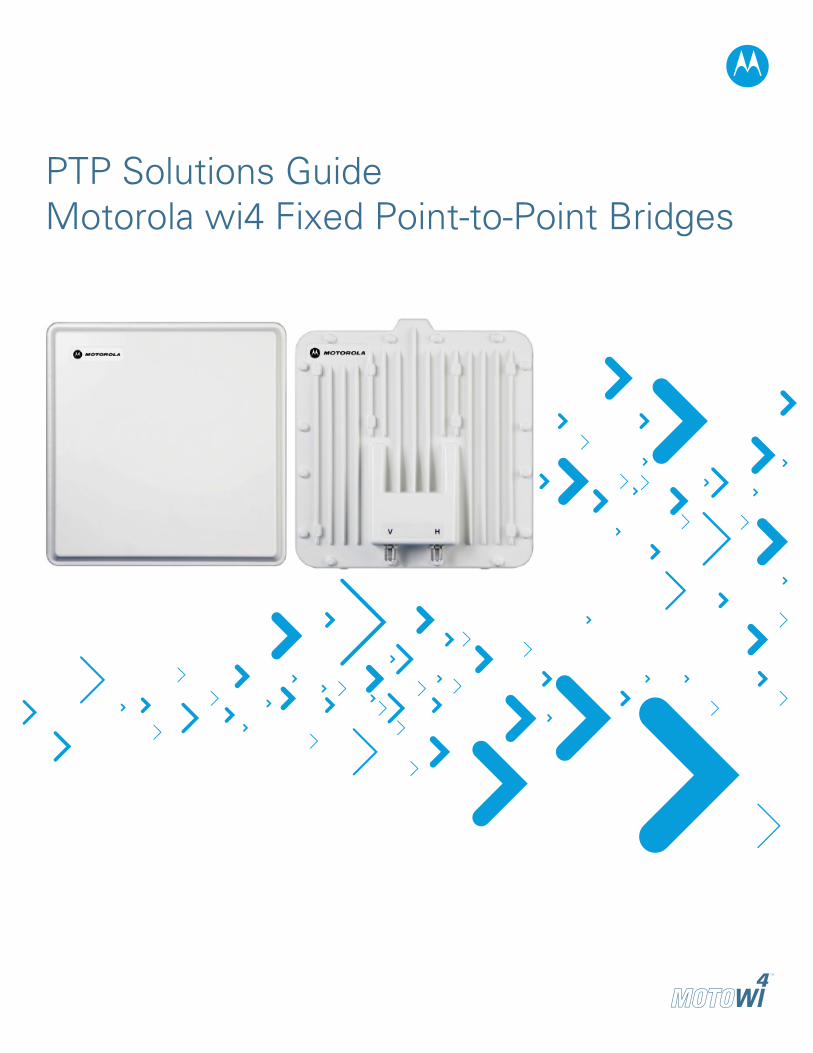
PTP Solutions GuideMotorola wi4 Fixed Point-to-Point Bridges
PTP SOLUTIONS GUIDE�
The contents of this Solutions Guide are subject to change without notice.
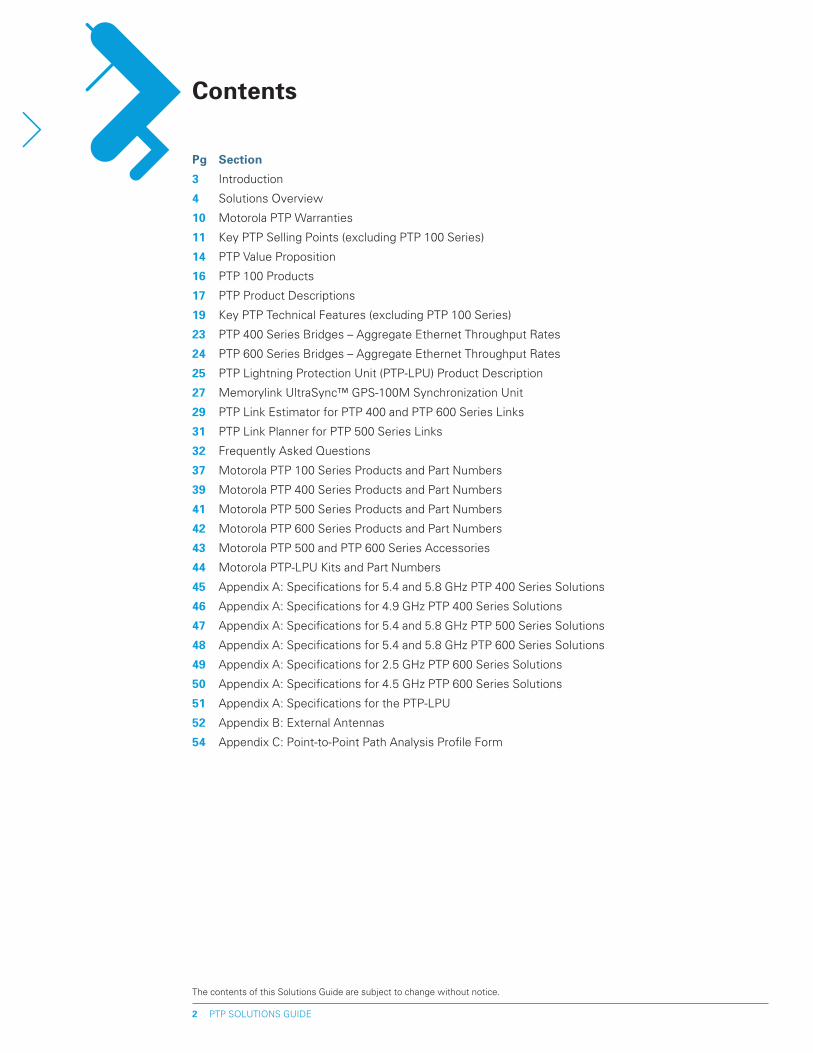
Contents
pg Section
3 Introduction
4 Solutions Overview
10 Motorola PTP Warranties
11 Key PTP Selling Points (excluding PTP 100 Series)
14 PTP Value Proposition
16 PTP 100 Products
17 PTP Product Descriptions
19 Key PTP Technical Features (excluding PTP 100 Series)
�3 PTP 400 Series Bridges – Aggregate Ethernet Throughput Rates
�4 PTP 600 Series Bridges – Aggregate Ethernet Throughput Rates
�5 PTP Lightning Protection Unit (PTP-LPU) Product Description
�7 Memorylink UltraSync™ GPS-100M Synchronization Unit
�9 PTP Link Estimator for PTP 400 and PTP 600 Series Links
31 PTP Link Planner for PTP 500 Series Links
3� Frequently Asked Questions
37 Motorola PTP 100 Series Products and Part Numbers
39 Motorola PTP 400 Series Products and Part Numbers
41 Motorola PTP 500 Series Products and Part Numbers
4� Motorola PTP 600 Series Products and Part Numbers
43 Motorola PTP 500 and PTP 600 Series Accessories
44 Motorola PTP-LPU Kits and Part Numbers
45 Appendix A: Specifications for 5.4 and 5.8 GHz PTP 400 Series Solutions
46 Appendix A: Specifications for 4.9 GHz PTP 400 Series Solutions
47 Appendix A: Specifications for 5.4 and 5.8 GHz PTP 500 Series Solutions
48 Appendix A: Specifications for 5.4 and 5.8 GHz PTP 600 Series Solutions
49 Appendix A: Specifications for 2.5 GHz PTP 600 Series Solutions
50 Appendix A: Specifications for 4.5 GHz PTP 600 Series Solutions
51 Appendix A: Specifications for the PTP-LPU
5� Appendix B: External Antennas
54 Appendix C: Point-to-Point Path Analysis Profile Form
PTP SOLUTIONS GUIDE3
The purpose of this document is to equip Motorola account teams and sales channel with the information needed to communicate the features and benefits of the Motorola wi4 Fixed Point-to-Point Wireless Solutions.
This is a living document that acts as a central point of reference for all marketing collateral. It is permissible to extract certain sections or subsections that apply to specific customer situations and incorporate them into sales collateral materials. This document should not be used for contracts or proposals in lieu of an official Motorola customer document.
Introduction
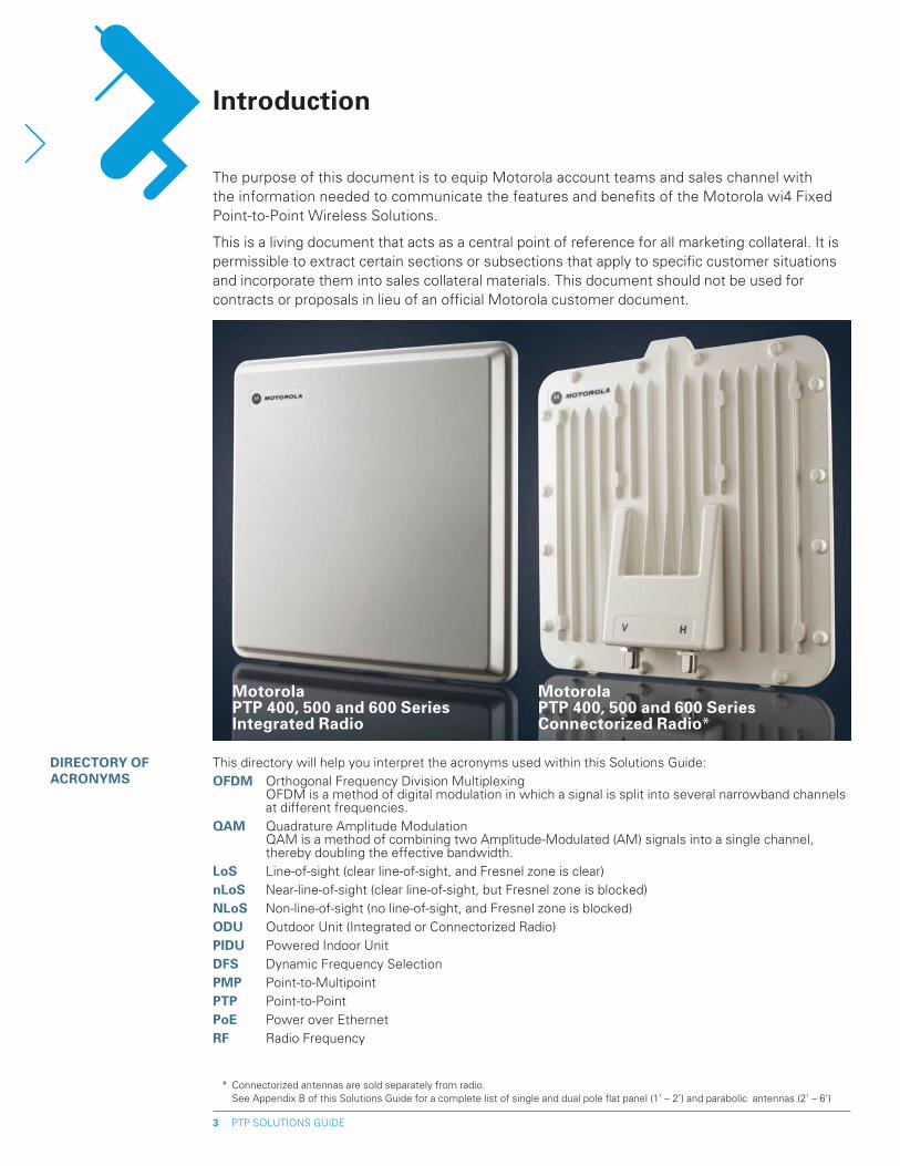
Motorola pTp 400, 500 and 600 Series Integrated Radio
* Connectorized antennas are sold separately from radio. See Appendix B of this Solutions Guide for a complete list of single and dual pole flat panel (1’ – 2’) and parabolic antennas (2’ – 6’)
Motorola pTp 400, 500 and 600 Series Connectorized Radio*
This directory will help you interpret the acronyms used within this Solutions Guide:OFDM Orthogonal Frequency Division Multiplexing
OFDM is a method of digital modulation in which a signal is split into several narrowband channels at different frequencies.
QAM Quadrature Amplitude Modulation QAM is a method of combining two Amplitude-Modulated (AM) signals into a single channel, thereby doubling the effective bandwidth.
LoS Line-of-sight (clear line-of-sight, and Fresnel zone is clear)nLoS Near-line-of-sight (clear line-of-sight, but Fresnel zone is blocked)NLoS Non-line-of-sight (no line-of-sight, and Fresnel zone is blocked)ODU Outdoor Unit (Integrated or Connectorized Radio)pIDU Powered Indoor UnitDFS Dynamic Frequency SelectionpMp Point-to-MultipointpTp Point-to-PointpoE Power over EthernetRF Radio Frequency
DIRECTORy OF ACRONyMS
PTP SOLUTIONS GUIDE4
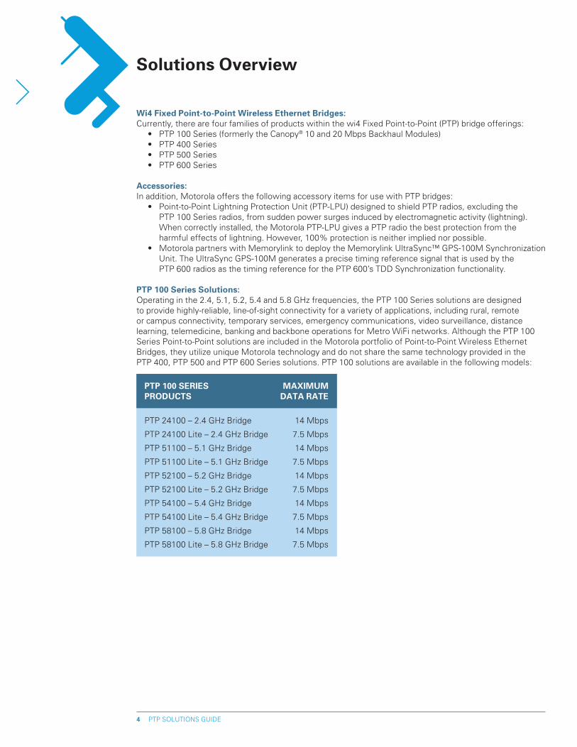
pTp 100 SERIES MAxIMUM pRODUCTS DATA RATE
PTP 24100 – 2.4 GHz Bridge 14 Mbps
PTP 24100 Lite – 2.4 GHz Bridge 7.5 Mbps
PTP 51100 – 5.1 GHz Bridge 14 Mbps
PTP 51100 Lite – 5.1 GHz Bridge 7.5 Mbps
PTP 52100 – 5.2 GHz Bridge 14 Mbps
PTP 52100 Lite – 5.2 GHz Bridge 7.5 Mbps
PTP 54100 – 5.4 GHz Bridge 14 Mbps
PTP 54100 Lite – 5.4 GHz Bridge 7.5 Mbps
PTP 58100 – 5.8 GHz Bridge 14 Mbps
PTP 58100 Lite – 5.8 GHz Bridge 7.5 Mbps
Solutions Overview
Wi4 Fixed point-to-point Wireless Ethernet Bridges: Currently, there are four families of products within the wi4 Fixed Point-to-Point (PTP) bridge offerings: • PTP 100 Series (formerly the Canopy® 10 and 20 Mbps Backhaul Modules) • PTP 400 Series • PTP 500 Series • PTP 600 Series
Accessories: In addition, Motorola offers the following accessory items for use with PTP bridges: • Point-to-Point Lightning Protection Unit (PTP-LPU) designed to shield PTP radios, excluding the
PTP 100 Series radios, from sudden power surges induced by electromagnetic activity (lightning). When correctly installed, the Motorola PTP-LPU gives a PTP radio the best protection from the harmful effects of lightning. However, 100% protection is neither implied nor possible.
• Motorola partners with Memorylink to deploy the Memorylink UltraSync™ GPS-100M Synchronization Unit. The UltraSync GPS-100M generates a precise timing reference signal that is used by the PTP 600 radios as the timing reference for the PTP 600’s TDD Synchronization functionality.
pTp 100 Series Solutions: Operating in the 2.4, 5.1, 5.2, 5.4 and 5.8 GHz frequencies, the PTP 100 Series solutions are designed to provide highly-reliable, line-of-sight connectivity for a variety of applications, including rural, remote or campus connectivity, temporary services, emergency communications, video surveillance, distance learning, telemedicine, banking and backbone operations for Metro WiFi networks. Although the PTP 100 Series Point-to-Point solutions are included in the Motorola portfolio of Point-to-Point Wireless Ethernet Bridges, they utilize unique Motorola technology and do not share the same technology provided in the PTP 400, PTP 500 and PTP 600 Series solutions. PTP 100 solutions are available in the following models:
PTP SOLUTIONS GUIDE5
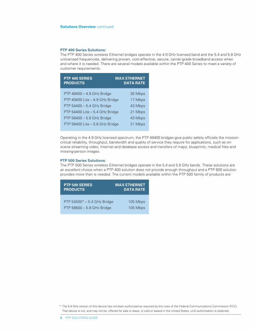
Operating in the 4.9 GHz licensed spectrum, the PTP 49400 bridges give public safety officials the mission-critical reliability, throughput, bandwidth and quality of service they require for applications, such as on-scene streaming video, Internet and database access and transfers of maps, blueprints, medical files and missing-person images.
pTp 500 Series Solutions: The PTP 500 Series wireless Ethernet bridges operate in the 5.4 and 5.8 GHz bands. These solutions are an excellent choice when a PTP 400 solution does not provide enough throughput and a PTP 600 solution provides more than is needed. The current models available within the PTP 500 family of products are:
pTp 400 Series Solutions: The PTP 400 Series wireless Ethernet bridges operate in the 4.9 GHz licensed band and the 5.4 and 5.8 GHz unlicensed frequencies, delivering proven, cost-effective, secure, carrier-grade broadband access when and where it is needed. There are several models available within the PTP 400 Series to meet a variety of customer requirements:
Solutions Overview continued
* The 5.4 GHz version of this device has not been authorized as required by the rules of the Federal Communications Commission (FCC).
That device is not, and may not be, offered for sale or lease, or sold or leased in the United States, until authorization is obtained.
pTp 400 SERIES MAx EThERNET pRODUCTS DATA RATE
PTP 49400 – 4.9 GHz Bridge 35 Mbps
PTP 49400 Lite – 4.9 GHz Bridge 17 Mbps
PTP 54400 – 5.4 GHz Bridge 43 Mbps
PTP 54400 Lite – 5.4 GHz Bridge 21 Mbps
PTP 58400 – 5.8 GHz Bridge 43 Mbps
PTP 58400 Lite – 5.8 GHz Bridge 21 Mbps
pTp 500 SERIES MAx EThERNET pRODUCTS DATA RATE
PTP 54500* – 5.4 GHz Bridge 105 Mbps
PTP 58600 – 5.8 GHz Bridge 105 Mbps
PTP SOLUTIONS GUIDE6
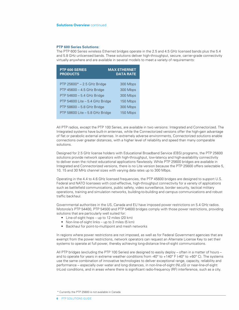
pTp 600 Series Solutions: The PTP 600 Series wireless Ethernet bridges operate in the 2.5 and 4.5 GHz licensed bands plus the 5.4 and 5.8 GHz unlicensed bands. These solutions deliver high-throughput, secure, carrier-grade connectivity virtually anywhere and are available in several models to meet a variety of requirements:
Solutions Overview continued
* Currently the PTP 25600 is not available in Canada
All PTP radios, except the PTP 100 Series, are available in two versions: Integrated and Connectorized. The Integrated systems have built-in antennas, while the Connectorized versions offer the high-gain advantage of flat or parabolic external antennas. In extremely adverse environments, Connectorized solutions enable connections over greater distances, with a higher level of reliability and speed than many comparable solutions.
Designed for 2.5 GHz license holders with Educational Broadband Service (EBS) programs, the PTP 25600 solutions provide network operators with high-throughput, low-latency and high-availability connectivity to deliver even the richest educational applications flawlessly. While PTP 25600 bridges are available in Integrated and Connectorized versions, there is no Lite version because the PTP 25600 offers selectable 5, 10, 15 and 30 MHz channel sizes with varying data rates up to 300 Mbps.
Operating in the 4.4 to 4.6 GHz licensed frequencies, the PTP 45600 bridges are designed to support U.S. Federal and NATO licensees with cost-effective, high-throughput connectivity for a variety of applications such as battlefield communications, public safety, video surveillance, border security, tactical military operations, training and simulation networks, building-to-building and campus communications and robust traffic backhaul.
Governmental authorities in the US, Canada and EU have imposed power restrictions on 5.4 GHz radios. Motorola’s PTP 54400, PTP 54500 and PTP 54600 bridges comply with those power restrictions, providing solutions that are particularly well suited for: • Line-of-sight hops – up to 12 miles (20 km) • Non-line-of-sight links – up to 3 miles (5 km) • Backhaul for point-to-multipoint and mesh networks
In regions where power restrictions are not imposed, as well as for Federal Government agencies that are exempt from the power restrictions, network operators can request an Alternate License Key to set their systems to operate at full power, thereby achieving long-distance line-of-sight communications.
All PTP bridges (excluding the PTP 100 Series) are designed to easily deploy – often in a matter of hours – and to operate for years in extreme weather conditions from -40° to +140° F (-40° to +60° C). The systems use the same combination of innovative technologies to deliver exceptional range, capacity, reliability and performance – especially over water and long distances, in non-line-of-sight (NLoS) or near-line-of-sight (nLos) conditions, and in areas where there is significant radio-frequency (RF) interference, such as a city.
pTp 600 SERIES MAx EThERNET pRODUCTS DATA RATE
PTP 25600* – 2.5 GHz Bridge 300 Mbps
PTP 45600 – 4.5 GHz Bridge 300 Mbps
PTP 54600 – 5.4 GHz Bridge 300 Mbps
PTP 54600 Lite – 5.4 GHz Bridge 150 Mbps
PTP 58600 – 5.8 GHz Bridge 300 Mbps
PTP 58600 Lite – 5.8 GHz Bridge 150 Mbps
ChOICE AND FLExIBILITy
While there are a number of internal and external factors (e.g., infrastructure complexities, budget, bandwidth requirements, path obstructions, applications, etc.) that will influence the decision about which Motorola solution best fits a specific customer situation, all Motorola point-to-point products offer exceptional advantages. As a general guideline, solutions are recommended for a wide variety of applications as shown in the following table.
pTp 100 Series: Delivering data rates up to 14 Mbps at distances up to 35 miles (56 km), these systems provide cost-effective, point-to-point connectivity in line-of-sight environments. Operating in the 2.4, 5.1, 5.2, 5.4 and 5.8 GHz frequencies, the systems offer consistent throughput, interference mitigation capabilities, weather resistant operations and a compact, rugged design, resulting in highly reliable communications. The PTP 100 is an excellent choice for WISPs and ISPs with low-capacity requirements.
pTp 100 Series Lite: Sharing the unique technology of the PTP 100, the PTP 100 Lite systems provide throughput rates to up 7.5 Mbps for line-of-sight applications.
pTp 400 Series – Integrated: Operating in the 4.9, 5.4 and 5.8 GHz bands with built-in antennas and up to 43 Mbps Ethernet data rates (PTP 54400 and PTP 58400) or 35 Mbps (PTP 49400), you can recommend the Integrated version of the PTP 400 Series bridges for near- and non-line-of-sight environments and over long distances.
pTp 400 Series Lite – Integrated: With the same technology of the PTP 400 Integrated systems and up to 21 Mbps Ethernet data rates (PTP 54400 and PTP 58400) or up to 17 Mbps (PTP 49400) – at less cost – these models are excellent choices for growing WISPs and ISPs, and for any budget-constrained organization that needs a robust solution to overcome interference and navigate obstructions. The Lite models of the PTP 400 Series systems are software upgradeable to 43 Mbps (PTP 54400 and PTP 58400) or 35 Mbps (PTP 49400) as throughput requirements increase.
ChOICE AND FLExIBILITy continued >
PTP SOLUTIONS GUIDE7
Motorola’s PTP solutions (excluding the PTP 100 Series) share many feature characteristics that enable effective link integrity and throughput, including: • Multiple-Input Multiple-Output (MIMO) • Intelligent Orthogonal Frequency Division Multiplexing (i-OFDM) • Advanced Spectrum Management with Intelligent Dynamic Frequency Selection (i-DFS) • Adaptive Modulation • Inherent Spatial Diversity • Best-in-class radios with the highest system gain in their class
This unique combination of technologies offers excellent reliability in high-interference environments and improves performance and uptime in challenging nLoS and NLoS applications. By providing a secure, high-throughput, short-range NLoS or long-range LoS connection, PTP systems (except the PTP 100 Series) offer a wireless alternative to remove network bottlenecks – at a fraction of the cost of wire-line alternatives.
MOTOwi4™ With the addition of the wi4 Fixed Point-to-Point Wireless Bridges to its MOTOwi4 portfolio, Motorola provides service providers and network operators with a robust family of point-to-point broadband wireless solutions. Motorola’s MOTOwi4 innovative wireless broadband solutions create, complement and complete IP networks. Delivering IP coverage to virtually all spaces, the MOTOwi4 portfolio includes wi4 Fixed, wi4 Mesh, wi4 Indoor and wi4 WiMAX solutions for high-speed connectivity over private and public networks.
Solutions Overview continued
PTP SOLUTIONS GUIDE8
Solutions Overview continued
ChOICE AND FLExIBILITy continued
pTp 400 Series – Connectorized: Combining all the innovative technology found in the Integrated version of the PTP 400 Series bridges with the high-gain advantage of external antennas, these solutions enable connections in extremely adverse environments, including deep non-line-of-sight and long-range line-of-sight.
pTp 400 Series Lite – Connectorized: With the reliability of the PTP 400 Connectorized systems at less cost, these solutions deliver up to 21 Mbps (PTP 54400 and PTP 58400) or up to 17 Mbps (PTP 49400) in adverse environments and are software upgradeable to 43 Mbps (PTP 54400 and PTP 58400) or 35 Mbps (PTP 49400) as bandwidth requirements grow.
pTp 500 Series – 5.4 and 5.8 Ghz Integrated: When connectivity requirements call for greater throughput than is provided by PTP 400 solutions but less than the PTP 600 solutions, the PTP 500 systems are an excellent alternative. Operating in the 5.4 and 5.8 GHz bands at up to 105 Mbps Ethernet data rate, these bridges can deliver carrier-class, high-speed performance in virtually any environment.
pTp 500 Series – Connectorized: With up to 155 miles (250 km) reach, the PTP 500 Connectorized model combines all the innovative technology found in the Integrated version with the high-gain advantage of external antennas, providing high-performance connectivity across extremely long distances and challenging environments.
pTp 500 Series Authorization Note: The 5.4 GHz version of this device has not been authorized as required by the rules of the Federal Communications Commission (FCC). That device is not, and may not be, offered for sale or lease, or sold or leased in the United States, until authorization is obtained.
pTp 600 Series – 5.4 and 5.8 Ghz Integrated: Operating in the 5.4 and 5.8 GHz bands with Ethernet data rates up to 300 Mbps and dual built-in antennas, these solutions are the perfect choice for any environment where high throughput is a major requirement and/or dual T1/E1 capability is needed.
pTp 600 Series Lite – 5.4 and 5.8 Ghz Integrated: With up to 150 Mbps Ethernet data rate and the same high-performance technology of the PTP 600 Integrated systems – at less cost – these systems are the right solutions for any environment where the application needs more speed and bandwidth than is provided by the PTP 400 and PTP 500 Series bridges and/or single T1/E1 capability is required. The Lite models of the 5.4 and 5.8 GHz PTP 600 Series bridges are software upgradeable to 300 Mbps as throughput requirements increase.
pTp 600 Series – 5.4 and 5.8 Ghz Connectorized: With all the same technology found in the Integrated version of the PTP 600 Series bridges and the high-gain advantage of external antennas, these solutions connect over greater distances at a higher level of reliability and speed than comparable wireless bridges.
pTp 600 Series Lite – 5.4 and 5.8 Ghz Connectorized: Delivering up to 150 Mbps in extremely adverse environments, these solutions have all the reliability of the PTP 600 Series Connectorized systems at less cost and are software upgradeable to 300 Mbps as bandwidth requirements increase.
ChOICE AND FLExIBILITy continued >
PTP SOLUTIONS GUIDE9
Solutions Overview continued
* In the PTP 25600 model, the 30 MHz Channel is not FCC compliant
ChOICE AND FLExIBILITy continued
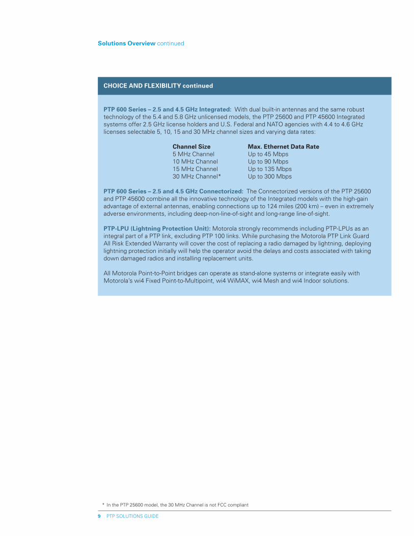
pTp 600 Series – �.5 and 4.5 Ghz Integrated: With dual built-in antennas and the same robust technology of the 5.4 and 5.8 GHz unlicensed models, the PTP 25600 and PTP 45600 Integrated systems offer 2.5 GHz license holders and U.S. Federal and NATO agencies with 4.4 to 4.6 GHz licenses selectable 5, 10, 15 and 30 MHz channel sizes and varying data rates:
Channel Size Max. Ethernet Data Rate 5 MHz Channel Up to 45 Mbps 10 MHz Channel Up to 90 Mbps 15 MHz Channel Up to 135 Mbps 30 MHz Channel* Up to 300 Mbps
pTp 600 Series – �.5 and 4.5 Ghz Connectorized: The Connectorized versions of the PTP 25600 and PTP 45600 combine all the innovative technology of the Integrated models with the high-gain advantage of external antennas, enabling connections up to 124 miles (200 km) – even in extremely adverse environments, including deep-non-line-of-sight and long-range line-of-sight.
pTp-LpU (Lightning protection Unit): Motorola strongly recommends including PTP-LPUs as an integral part of a PTP link, excluding PTP 100 links. While purchasing the Motorola PTP Link Guard All Risk Extended Warranty will cover the cost of replacing a radio damaged by lightning, deploying lightning protection initially will help the operator avoid the delays and costs associated with taking down damaged radios and installing replacement units.
All Motorola Point-to-Point bridges can operate as stand-alone systems or integrate easily with Motorola’s wi4 Fixed Point-to-Multipoint, wi4 WiMAX, wi4 Mesh and wi4 Indoor solutions.
1�-Month Standard Warranty
The purchase price of a PTP radio includes a one-year limited warranty on all hardware components, plus minor software enhancements as they become available. The hardware warranty provides a 30-day repair-and- return program for damaged parts. Each warranty must be registered online to activate the free 12-month warranty period and receive notification of software updates. To register a standard warranty, go to www.motorola.com/ptp.
While our point-to-point products are engineered and quality-tested to withstand severe conditions, occasionally hardware components can fail as a result of extreme situations. Therefore, Motorola offers the following equipment coverage and repair-and-replacement options to support its PTP solutions (excluding the PTP 100 Series solutions):
PTP SOLUTIONS GUIDE10
Motorola pTp Warranties
Link Guard All Risk Extended Warranty
The Motorola PTP Link Guard All Risk Extended Warranty upgrades the initial 12-month warranty to the 24-hour Advanced Replacement program and All Risk equipment coverage for any and all types of equipment damage, including lightning damage, dropped units, vandalism, fire or any other hardware damage. The All Risk coverage with 24-hour Advanced Replacement can be extended through the second, third or fifth years of ownership.
This warranty option ensures that replacement product will be shipped from the United Kingdom on the next business day after receipt of a confirmed RMA. All shipping materials are provided when the RMA is approved, and Motorola picks up shipping costs in both directions. While the replacement shipping process will be started immediately, delivery time will be dependent upon customs and ship-to location.
At the time of equipment purchase or prior to the end of the 12-month standard warranty, Motorola recommends that organizations purchase one of the following Extended Warranties to receive upgraded and/or extended equipment coverage:
Link protector Extended Warranty
The Motorola PTP Link Protector Extended Warranty extends the initial 12-month standard equipment warranty with 30-day repair-and-replacement terms through the second, third or fifth years of ownership. This option is typically chosen when an organization purchases one or more spare PTP links to use as replacement units, and fast repair and return for damaged hardware components is not required.
pTp Software Maintenance Contract
After the initial 12-month standard warranty, an annual Software Maintenance Contract must be obtained to continue receiving software updates and technical support. The contract includes minor software enhancements as they become available and 24/7 telephone support. Technical support is provided under an assigned Customer Contract Number (CCN) or the MAC address of the unit that is covered under the initial 12-month standard warranty. Contracts are available through Motorola’s authorized reseller partners or directly from the Technical Support Center using a credit card.
PTP SOLUTIONS GUIDE11
Key pTp Selling points (excluding pTp 100 Series)
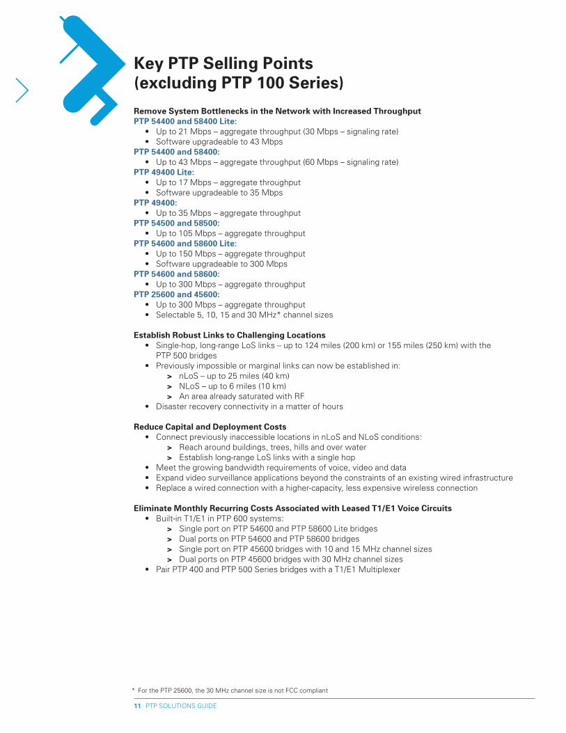
Remove System Bottlenecks in the Network with Increased Throughput pTp 54400 and 58400 Lite: • Up to 21 Mbps – aggregate throughput (30 Mbps – signaling rate) • Software upgradeable to 43 MbpspTp 54400 and 58400: • Up to 43 Mbps – aggregate throughput (60 Mbps – signaling rate) pTp 49400 Lite: • Up to 17 Mbps – aggregate throughput • Software upgradeable to 35 MbpspTp 49400: • Up to 35 Mbps – aggregate throughputpTp 54500 and 58500: • Up to 105 Mbps – aggregate throughputpTp 54600 and 58600 Lite: • Up to 150 Mbps – aggregate throughput • Software upgradeable to 300 MbpspTp 54600 and 58600: • Up to 300 Mbps – aggregate throughput pTp �5600 and 45600: • Up to 300 Mbps – aggregate throughput • Selectable 5, 10, 15 and 30 MHz* channel sizes
Establish Robust Links to Challenging Locations • Single-hop, long-range LoS links – up to 124 miles (200 km) or 155 miles (250 km) with the
PTP 500 bridges • Previously impossible or marginal links can now be established in: > nLoS – up to 25 miles (40 km) > NLoS – up to 6 miles (10 km) > An area already saturated with RF • Disaster recovery connectivity in a matter of hours
Reduce Capital and Deployment Costs • Connect previously inaccessible locations in nLoS and NLoS conditions: > Reach around buildings, trees, hills and over water > Establish long-range LoS links with a single hop • Meet the growing bandwidth requirements of voice, video and data • Expand video surveillance applications beyond the constraints of an existing wired infrastructure • Replace a wired connection with a higher-capacity, less expensive wireless connection
Eliminate Monthly Recurring Costs Associated with Leased T1/E1 Voice Circuits • Built-in T1/E1 in PTP 600 systems: > Single port on PTP 54600 and PTP 58600 Lite bridges > Dual ports on PTP 54600 and PTP 58600 bridges > Single port on PTP 45600 bridges with 10 and 15 MHz channel sizes > Dual ports on PTP 45600 bridges with 30 MHz channel sizes • Pair PTP 400 and PTP 500 Series bridges with a T1/E1 Multiplexer
* For the PTP 25600, the 30 MHz channel size is not FCC compliant
PTP SOLUTIONS GUIDE1�
Key pTp Selling points continued
provide Secure Communications • Pre-programmed to communicate only with a matched partner to eliminate “man-in-the-middle”
attacks • Utilize a complex proprietary scrambling mechanism for data transmission • Another layer of security is available with 128-bit and 256-bit AES encryption (optional)
Easy Link planning • Optimize a PTP 400 or PTP 600 Series link before deployment using the Motorola PTP Link Estimator
tool which simulates a link’s performance and allows variables to be changed to instantly see the effects on performance
• Path calculations for any PTP 500 Series solutions must be done using the all new PTP Link Planner which lets customers quickly and easily optimize a single link or multiple links simultaneously; ultimately, this new tool will replace the PTP Link Estimator
Reduce Overall Operating Costs • Operators can remotely manage, monitor and optimize link performance via comprehensive web-
based management • Small form factor reduces the costs of leasing tower space • More links can be co-located without creating excess interference: > Narrow 8° antenna beam width – dual polarized antennas > Narrow Channels: • 12 MHz Channel for 5.8 and 5.4 GHz PTP 400 Series bridges • 10 MHz Channel for 4.9 GHz PTP 400 bridges • 15 MHz Channel for 5.8 and 5.4 GHz PTP 500 Series bridges • 30 MHz Channel for 5.8 and 5.4 GHz PTP 600 Series bridges • Selectable 5, 10, 15 and 30 MHz channels for 2.5 and 4.5 GHz PTP 600 Series bridges
Deliver high Availability in Noisy and Constantly Changing RF Environments • Unique combination of interference mitigation techniques: > Multiple-Input Multiple-Output (MIMO) transmits multiple signals which are
de-correlated temporarily and spatially; being de-correlated, each path fades at different times, and the receiver is able to select the best signal at any time, resulting in better performance and link availability
> Advanced Spectrum Management with i-DFS (intelligent Dynamic Frequency Selection) automatically changes channels to avoid interference and combat fading without user intervention
> Adaptive Modulation ensures maximum throughput optimized for the radio path even as path characteristics change
> Time Division Duplexing (TDD) Synchronization (pTp 600 Series radios): Using a timing reference from the Memorylink UltraSync™ GPS-100M synchronization unit, the PTP 600’s TDD Synchronization capability synchronizes transmit and receive signals to minimize interference and promote optimal spectral reuse. By timing and synchronizing transmit and receive signals, network operators can co-locate multiple PTP radios on a rooftop or tower with greatly reduced interference
Bring Reliable, high-Capacity Connectivity to a Wide Variety of Applications • Deliver high bandwidth for demanding applications, such as Voice-over-IP, IP gaming, video
surveillance, distance learning and telemedicine • Support public safety officials with high-bandwidth, super-reliable connectivity for voice, video and data communications (PTP 49400 4.9 GHz system)
PTP SOLUTIONS GUIDE13
Key pTp Selling points continued
• Connect buildings in a campus setting • Create a seamless local-area-network between a company headquarters and a warehouse, branch
office, service center or other facility • Backhaul more local loops using a single link • Extend T1/E1 PBX circuits • Support sophisticated convergent, multimedia applications • Backhaul traffic from multiple wireless LAN access points to a point of presence • Fast, cost-effective deployment for disaster recovery and temporary services • Combine T1/E1 and Ethernet ports in a single radio • Backhaul traffic from Motorola Point-to-Multipoint, WiMAX and Mesh networks • Implement a WiMAX-ready backhaul solution • Provide 2.5 GHz license holders with high-throughput, spectrally-efficient connectivity to deliver the
richest educational applications reliably (PTP 25600 2.5 GHz system) • Provide U.S. Federal and NATO 4.4 to 4.6 GHz license holders with the high-performance, reliable
connectivity they need to support strategic and tactical communications in difficult RF environments and geographies (PTP 45600 4.5 GHz system)
Offer Network Design Flexibility • Choose from several platforms – PTP 400 Series, PTP 400 Series Lite, PTP 500 Series, PTP 600 Series,
PTP 600 Series Lite – each available in two versions – Integrated or Connectorized • Wi4 Fixed PTP 400, PTP 500 and PTP 600 Series systems integrate with Motorola’s wi4 Fixed Point-to-
Multipoint (Canopy®), wi4 Mesh, wi4 WiMAX and wi4 Indooor networks • Migration path to higher bandwidths: > 21 Mbps to 43 Mbps (PTP 54400 and PTP 58400) > 17 Mbps to 35 Mbps (PTP 49400) > 150 Mbps to 300 Mbps (PTP 54600 and PTP 58600) > Selectable channel sizes and data rates with PTP 25600 and PTP 45600 bridges • Dual powering options (±48V DC and AC) provide several different power supply configurations such
as ±48VDC wind or solar power and redundant configurations
Easy, Flexible System Management • Web or SNMP V1/2c using MIB-II or private PTP MIB • Canopy® Prizm • WiMAX MIB support for end-to-end management of a WiMAX network
PTP SOLUTIONS GUIDE14
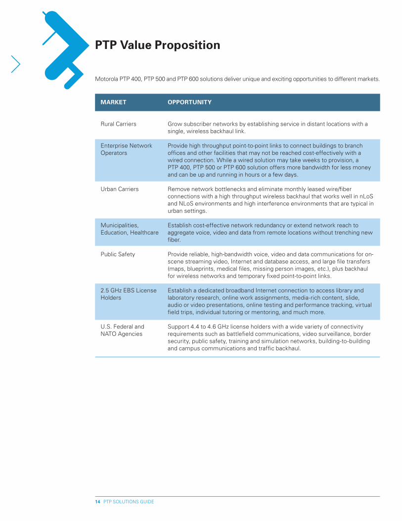
pTp Value proposition
uctionMARKET
Rural Carriers
Enterprise Network Operators
Urban Carriers
Municipalities, Education, Healthcare
Public Safety
2.5 GHz EBS License Holders
U.S. Federal and NATO Agencies
OppORTUNITy
Grow subscriber networks by establishing service in distant locations with a single, wireless backhaul link.
Provide high throughput point-to-point links to connect buildings to branch offices and other facilities that may not be reached cost-effectively with a wired connection. While a wired solution may take weeks to provision, a PTP 400, PTP 500 or PTP 600 solution offers more bandwidth for less money and can be up and running in hours or a few days.
Remove network bottlenecks and eliminate monthly leased wire/fiber connections with a high throughput wireless backhaul that works well in nLoS and NLoS environments and high interference environments that are typical in urban settings. Establish cost-effective network redundancy or extend network reach to aggregate voice, video and data from remote locations without trenching new fiber. Provide reliable, high-bandwidth voice, video and data communications for on-scene streaming video, Internet and database access, and large file transfers (maps, blueprints, medical files, missing person images, etc.), plus backhaul for wireless networks and temporary fixed point-to-point links.
Establish a dedicated broadband Internet connection to access library and laboratory research, online work assignments, media-rich content, slide, audio or video presentations, online testing and performance tracking, virtual field trips, individual tutoring or mentoring, and much more.
Support 4.4 to 4.6 GHz license holders with a wide variety of connectivity requirements such as battlefield communications, video surveillance, border security, public safety, training and simulation networks, building-to-building and campus communications and traffic backhaul.
Motorola PTP 400, PTP 500 and PTP 600 solutions deliver unique and exciting opportunities to different markets.
PTP SOLUTIONS GUIDE15
pTp Value proposition continued
VALUE
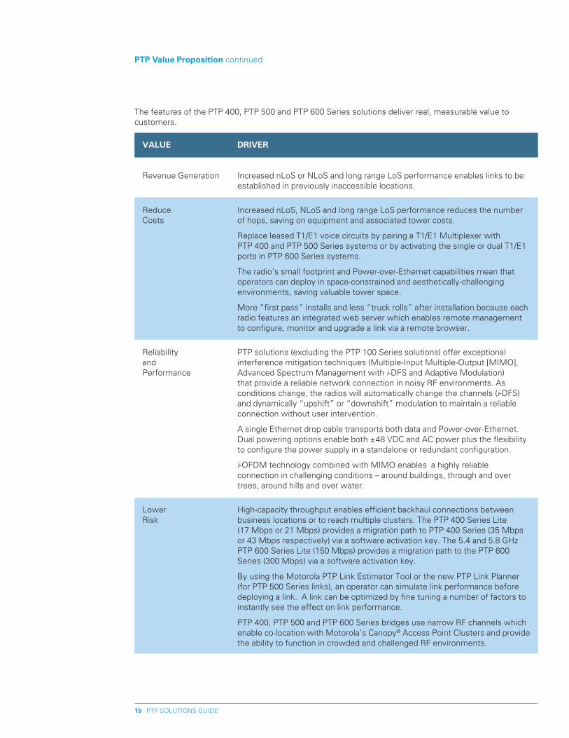
Revenue Generation
Reduce Costs
Reliability and Performance
Lower Risk
DRIVER
Increased nLoS or NLoS and long range LoS performance enables links to be established in previously inaccessible locations.
Increased nLoS, NLoS and long range LoS performance reduces the number of hops, saving on equipment and associated tower costs.
Replace leased T1/E1 voice circuits by pairing a T1/E1 Multiplexer with PTP 400 and PTP 500 Series systems or by activating the single or dual T1/E1 ports in PTP 600 Series systems.
The radio’s small footprint and Power-over-Ethernet capabilities mean that operators can deploy in space-constrained and aesthetically-challenging environments, saving valuable tower space.
More “first pass” installs and less “truck rolls” after installation because each radio features an integrated web server which enables remote management to configure, monitor and upgrade a link via a remote browser.
PTP solutions (excluding the PTP 100 Series solutions) offer exceptional interference mitigation techniques (Multiple-Input Multiple-Output [MIMO], Advanced Spectrum Management with i-DFS and Adaptive Modulation) that provide a reliable network connection in noisy RF environments. As conditions change, the radios will automatically change the channels (i-DFS) and dynamically “upshift” or “downshift” modulation to maintain a reliable connection without user intervention.
A single Ethernet drop cable transports both data and Power-over-Ethernet. Dual powering options enable both ±48 VDC and AC power plus the flexibility to configure the power supply in a standalone or redundant configuration.
i-OFDM technology combined with MIMO enables a highly reliable connection in challenging conditions – around buildings, through and over trees, around hills and over water.
High-capacity throughput enables efficient backhaul connections between business locations or to reach multiple clusters. The PTP 400 Series Lite (17 Mbps or 21 Mbps) provides a migration path to PTP 400 Series (35 Mbps or 43 Mbps respectively) via a software activation key. The 5.4 and 5.8 GHz PTP 600 Series Lite (150 Mbps) provides a migration path to the PTP 600 Series (300 Mbps) via a software activation key.
By using the Motorola PTP Link Estimator Tool or the new PTP Link Planner (for PTP 500 Series links), an operator can simulate link performance before deploying a link. A link can be optimized by fine tuning a number of factors to instantly see the effect on link performance.
PTP 400, PTP 500 and PTP 600 Series bridges use narrow RF channels which enable co-location with Motorola’s Canopy® Access Point Clusters and provide the ability to function in crowded and challenged RF environments.
The features of the PTP 400, PTP 500 and PTP 600 Series solutions deliver real, measurable value to customers.
PTP SOLUTIONS GUIDE16
pTp 100 products
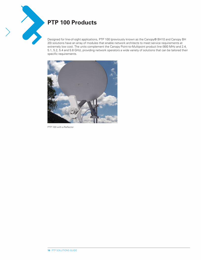
Designed for line-of-sight applications, PTP 100 (previously known as the Canopy® BH10 and Canopy BH 20) solutions have an array of modules that enable network architects to meet service requirements at extremely low cost. The units complement the Canopy Point-to-Multipoint product line (900 MHz and 2.4, 5.1, 5.2, 5.4 and 5.8 GHz), providing network operators a wide variety of solutions that can be tailored their specific requirements.
PTP 100 with a Reflector
PTP SOLUTIONS GUIDE17
pTp product Descriptions
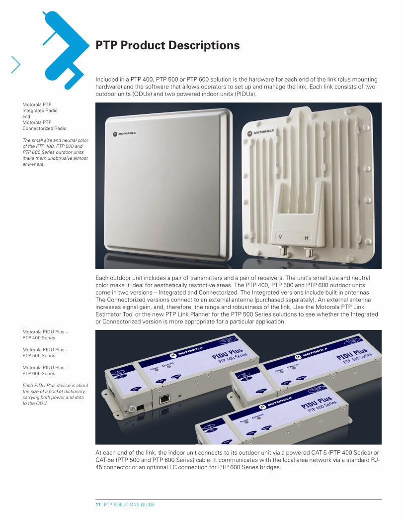
Included in a PTP 400, PTP 500 or PTP 600 solution is the hardware for each end of the link (plus mounting hardware) and the software that allows operators to set up and manage the link. Each link consists of two outdoor units (ODUs) and two powered indoor units (PIDUs).
At each end of the link, the indoor unit connects to its outdoor unit via a powered CAT-5 (PTP 400 Series) or CAT-5e (PTP 500 and PTP 600 Series) cable. It communicates with the local area network via a standard RJ-45 connector or an optional LC connection for PTP 600 Series bridges.
Each outdoor unit includes a pair of transmitters and a pair of receivers. The unit’s small size and neutral color make it ideal for aesthetically restrictive areas. The PTP 400, PTP 500 and PTP 600 outdoor units come in two versions – Integrated and Connectorized. The Integrated versions include built-in antennas. The Connectorized versions connect to an external antenna (purchased separately). An external antenna increases signal gain, and, therefore, the range and robustness of the link. Use the Motorola PTP Link Estimator Tool or the new PTP Link Planner for the PTP 500 Series solutions to see whether the Integrated or Connectorized version is more appropriate for a particular application.
Motorola PTP Integrated RadioandMotorola PTP Connectorized Radio
The small size and neutral color of the PTP 400, PTP 500 and PTP 600 Series outdoor units make them unobtrusive almost anywhere.
Motorola PIDU Plus – PTP 400 Series
Motorola PIDU Plus – PTP 500 Series
Motorola PIDU Plus – PTP 600 Series
Each PIDU Plus device is about the size of a pocket dictionary, carrying both power and data to the ODU.
PTP SOLUTIONS GUIDE18
pTp product Descriptions continued
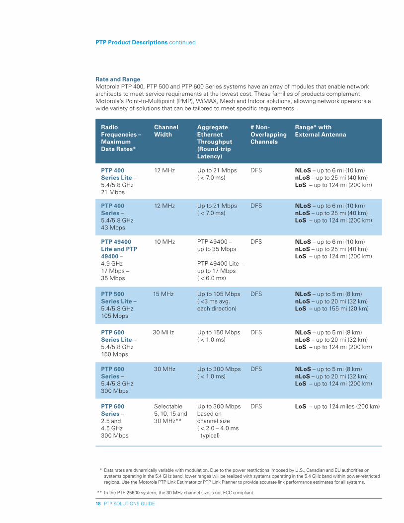
Rate and Range Motorola PTP 400, PTP 500 and PTP 600 Series systems have an array of modules that enable network architects to meet service requirements at the lowest cost. These families of products complement Motorola’s Point-to-Multipoint (PMP), WiMAX, Mesh and Indoor solutions, allowing network operators a wide variety of solutions that can be tailored to meet specific requirements.
* Data rates are dynamically variable with modulation. Due to the power restrictions imposed by U.S., Canadian and EU authorities on systems operating in the 5.4 GHz band, lower ranges will be realized with systems operating in the 5.4 GHz band within power-restricted regions. Use the Motorola PTP Link Estimator or PTP Link Planner to provide accurate link performance estimates for all systems.
** In the PTP 25600 system, the 30 MHz channel size is not FCC compliant.
Radio Frequencies – Maximum Data Rates*
Channel Width
Aggregate Ethernet Throughput (Round-trip Latency)
# Non- Overlapping Channels
Range* with External Antenna
pTp 400 Series Lite – 5.4/5.8 GHz21 Mbps
12 MHz Up to 21 Mbps ( < 7.0 ms)
DFS NLoS – up to 6 mi (10 km)nLoS – up to 25 mi (40 km)LoS – up to 124 mi (200 km)
pTp 400 Series – 5.4/5.8 GHz43 Mbps
12 MHz Up to 21 Mbps ( < 7.0 ms)
DFS NLoS – up to 6 mi (10 km)nLoS – up to 25 mi (40 km)LoS – up to 124 mi (200 km)
pTp 49400 Lite and pTp 49400 – 4.9 GHz17 Mbps – 35 Mbps
10 MHz PTP 49400 – up to 35 Mbps
PTP 49400 Lite – up to 17 Mbps( < 6.0 ms)
DFS NLoS – up to 6 mi (10 km)nLoS – up to 25 mi (40 km)LoS – up to 124 mi (200 km)
pTp 600 Series Lite – 5.4/5.8 GHz150 Mbps
30 MHz Up to 150 Mbps ( < 1.0 ms)
DFS NLoS – up to 5 mi (8 km)nLoS – up to 20 mi (32 km)LoS – up to 124 mi (200 km)
pTp 600 Series – 5.4/5.8 GHz300 Mbps
30 MHz Up to 300 Mbps ( < 1.0 ms)
DFS NLoS – up to 5 mi (8 km)nLoS – up to 20 mi (32 km)LoS – up to 124 mi (200 km)
pTp 600 Series – 2.5 and 4.5 GHz300 Mbps
Selectable 5, 10, 15 and 30 MHz**
Up to 300 Mbps based on channel size( < 2.0 – 4.0 ms typical)
DFS LoS – up to 124 miles (200 km)
pTp 500 Series Lite – 5.4/5.8 GHz105 Mbps
15 MHz Up to 105 Mbps( <3 ms avg. each direction)
DFS NLoS – up to 5 mi (8 km)nLoS – up to 20 mi (32 km)LoS – up to 155 mi (20 km)
PTP SOLUTIONS GUIDE19
Regardless of the application, the Motorola PTP systems (excluding the PTP 100 Series) create a wireless Ethernet link between two points. Each point consists of an indoor unit and an outdoor unit. The two endpoints communicate via radio waves over channels varying in bandwidth between 5 MHz (PTP 25600* and PTP 45600), 12 MHz (PTP 400 Series), 15 MHz (PTP 500 Series) and 30 MHz (PTP 600 Series). The channel raster is designed to ensure maximum flexibility in deciding channel occupancy. This greatly increases the probability that customers can find at least one usable channel in an already crowded hub-site.
Each outdoor unit utilizes two transceivers coupled to a baseband converter. The two pairs of transceivers connect with one another, enabling four different transmitter/receiver combinations – and so four distinct transmission beams. This greatly reduces the effects of fading and increases the probability that data will get through.
PTP 400, 500 and 600 Series bridges use a unique combination of innovative technologies to deliver exceptional range, capacity, reliability and performance – especially in nLoS or NLoS conditions, and in areas where there is significant RF interference, such as a city. The nLoS and NLoS capabilities provide a high tolerance for obstructions and enable network operators to establish network connections over hills, around buildings, through trees and over water.
pTp 400, pTp 500 and pTp 600 Series Similarities PTP 400, 500 and 600 Series bridges share many feature characteristics, including: • Advanced Spectrum Management with Intelligent Dynamic Frequency Selection (i-DFS)
automatically changes channels to avoid interference and combat link fading without user intervention. At power-up and throughout operation, the radio samples the band up to 400 times a second and automatically switches to the clearest channel. The 30-day, time-stamped database alerts the network operator to any interference that does exist and provides statistics to help analyze these patterns. This Advanced Spectrum Management capability creates virtually interference-free performance in the band.
• Adaptive Modulation ensures maximum throughput optimized for the radio path, even as path characteristics change. The transmitter and receiver negotiate the highest mutually sustainable data rate – then dynamically “upshift” and “downshift” the rate as RF conditions change.
• Dual polarized Antennas – two transmitters and two receivers are used to establish a link, enabling four different transmitter/receiver combinations. By creating four distinct transmission beams, the chances that data will get through increase significantly.
• Multiple-Input Multiple-Output (MIMO) – transmits multiple signals which are de-correlated temporarily and spatially. Being de-correlated, each path fades at different times, and the receiver is able to select the best signal at any time, resulting in better performance and link availability. The radio radiates multiple beams from the antenna – the effect of which significantly protects against fading and increases the probability of making a connection and reading the transmitted data. Plus, the radio will intelligently switch to “Dual Payload” mode if RF conditions will support it. In this mode, different data can be transmitted in parallel on each transmitter, effectively doubling the bandwidth at the higher modulation rates.
• Intelligent Orthogonal Frequency Division Multiplexing (i-OFDM) – in addition to MIMO transmitting the data twice, i-OFDM sends transmissions over multiple frequencies, or sub-carriers. The multiple sub-carriers result in higher spectral efficiency and higher resistance to:
(1) Multi-path interference which occurs when objects in the air gap split a beam into parts that travel different paths and interfere with each other at the receiver.
(2) Frequency selective fading which occurs when amplitudes of arriving signals cancel each other out at the receiver.
In typical radios this would be a problem, but with PTP 400, 500 and 600 Series radios, i-OFDM actually helps the radios re-correlate the interfering signals, improving the chance of receiving the signal through reflective behavior.
Key pTp Technical Features (excluding pTp 100 Series)
* Currently the PTP 25600 is not available in Canada
PTP SOLUTIONS GUIDE�0
• Built-in Security is provided via a complex proprietary-scrambling mechanism and matched-radios technique that provides excellent over-the-air security for data transmissions. At installation, each outdoor unit comes with the MAC address of the other outdoor unit to which it will connect. The preset addresses enable the system’s security features and allow the two units to communicate only with each other. An added layer of security can be applied with FIPS-197 compliant, 128-Bit or 256-Bit AES Encryption (optional).
• physical Form Factor – PTP 400, 500 and 600 Series systems share the same form factor and are offered in Integrated or Connectorized* (external antennas) versions. The Powered Indoor Unit (PIDU Plus) supports ±48VDC and AC.
Motorola pTp 400, 500 and 600 Series DifferencesThe differences between PTP 400, PTP 500 and PTP 600 Series systems providethe operator with a selection of choices based on features, bandwidth requirements and price points to cost effectively establish a long range LoS or a challenging nLoS or NLoS wireless link. The primary feature differences are: • hardware > PTP 400 Series bridges use different hardware and electronics than
PTP 500 and PTP 600 Series bridges > There is no difference in hardware between PTP 400 and PTP 400 Lite bridges > There is no difference in hardware between PTP 600 and PTP 600 Lite bridges > The PTP 25600 and PTP 45600 models within the PTP 600 family of solutions are not available
in a Lite version because the systems offer selectable 5, 10, 15 and 30 MHz** channel sizes with varying data rates based on channel size
• Software > Maximum bandwidth of the PTP 400 and PTP 400 Lite is determined by software key; a
PTP 400 Lite (21 or 17 Mbps model) can be easily upgraded to a PTP 400 (43 or 35 Mbps model) > Maximum bandwidth of the PTP 600 and PTP 600 Lite is determined by software key; a
PTP 600 Series Lite (150 Mbps) can be easily upgraded to a PTP 600 (300 Mbps) > Maximum bandwidth of the PTP 25600 and PTP 45600 models (in the PTP 600 family of
solutions) is determined by the channel size selected: • 5 MHz Channel – 45 Mbps • 10 MHz Channel – 90 Mbps • 15 MHz Channel – 135 Mbps • 30 MHz Channel ** – 300 Mbps > PTP 400 Series bridges run on entirely different software than PTP 500 and PTP 600 Series
systems • power Supply*** (PIDU Plus) – key differences between the PTP 400, PTP 500 and the PTP 600
Series PIDU Plus are: > PTP 400 Series PIDU Plus - powers the radio over CAT5 100 Base-T Ethernet; AC and ±48VDC;
100 Base –T PoE > PTP 500 Series PIDU Plus – powers the radio over CAT 5e 100 Base – T PoE > PTP 600 Series PIDU Plus - powers the radio over CAT 5e 1000 Base-T Gigabit Ethernet; AC
and ±48VDC; 1000 Base-T PoE • Spectrum > 5.4 and 5.8 GHz PTP 400 Series bridges use 12 MHz of spectrum > 4.9 GHz PTP 400 Series (PTP 49400) bridges use 10 MHz of spectrum > 5.4 and 5.8 GHz PTP 500 Series bridges use 15 MHz of spectrum > 5.4 and 5.8 GHz PTP 600 Series bridges use 30 MHz of spectrum > 2.5 and 4.5 GHz PTP 600 Series bridges (PTP 25600 and PTP 45600 models) offer selectable 5,
10, 15 and 30 MHz ** channel sizes
Key pTp Technical Features continued
* Connectorized antennas are sold separately. See Appendix B for a list of 1-2’ Flat Panel and 2-6’ Parabolic Antennas. ** In the PTP 25600 system, the 30 MHz channel is not FCC compliant *** Power Supply is outdoor-temperature rated at -40° F (-40°C) to 140° F (+60°C) and requires a weatherproof enclosure when mounted
outdoors.
PTP SOLUTIONS GUIDE�1
• Modulation > PTP 400 Series bridges range from BPSK to 64 QAM > PTP 500 Series bridges range from BPSK to 64 QAM > PTP 600 Series bridges range from BPSK to 256 QAM • Time Division Duplex (TDD) Synchronization in pTp 600 Series solutions > Times and synchronizes transmit and receive signals > Improved frequency reuse enables co-location of multiple PTP radios on a single rooftop or
tower with greatly reduced interference > Requires a Memorylink UltraSync™ GPS-100M synchronization unit that generates a precise
timing-reference signal that originates from the atomic clocks on GPS satellites orbiting the earth; this signal is fed to the PTP 600 radio and used as the timing reference for the PTP 600’s TDD functionality
• T1/E1 Capability > A PTP 400 or PTP 500 Series system must be paired with a T1/E1 Multiplexer to transport
TDM traffic over the bridge; each bridge has a “TDM Mode” software feature that generates a new set of Adaptive Modulation margins, reducing the probability of code-word errors (and hence packet loss); the multiplexer converts the data stream from T1/E1 ports into packets for transmission over the bridge’s Ethernet port; at the other end of the link, a second multiplexer converts the packets back into TDM traffic, carrying the traffic seamlessly and reliably from one location to another
> A PTP 600 Series system has built-in T1/E1 ports in the radio: PTP 600 Series Lite has one built-in T1/E1 port and PTP 600 Series has two; PTP 600 Series bridges can also be paired with a T1/E1 Multiplexer to transport voice
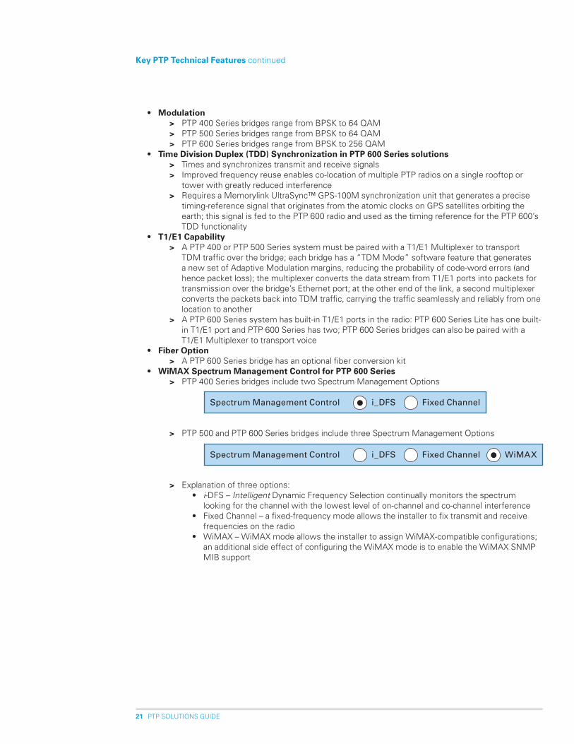
• Fiber Option > A PTP 600 Series bridge has an optional fiber conversion kit • WiMAx Spectrum Management Control for pTp 600 Series > PTP 400 Series bridges include two Spectrum Management Options
> PTP 500 and PTP 600 Series bridges include three Spectrum Management Options
> Explanation of three options: • i-DFS – Intelligent Dynamic Frequency Selection continually monitors the spectrum
looking for the channel with the lowest level of on-channel and co-channel interference • Fixed Channel – a fixed-frequency mode allows the installer to fix transmit and receive
frequencies on the radio • WiMAX – WiMAX mode allows the installer to assign WiMAX-compatible configurations;
an additional side effect of configuring the WiMAX mode is to enable the WiMAX SNMP MIB support
Key pTp Technical Features continued
Spectrum Management Control i_DFS Fixed Channel
Spectrum Management Control i_DFS Fixed Channel WiMAX
Characteristic
Band
Range*
Spectrum
5.4 Ghz pTp 54400
UNII > 5.470 – 5.725 GHz
LoS > Up to 12 mi (20 km)
NLoS >
Up to 3 mi (5 km)
250 MHz
5.8 Ghz pTp 58400
ISM > 5.725 – 5.850 GHz
LoS > Up to 124 mi (200 km)
NLoS > Up to 6 mi (10 km)
125 MHz
5.4 Ghz **pTp 54500
UNII > 5.470 – 5.725 GHz
LoS > Up to 12 mi (20 km)
NLoS >
Up to 3 mi (5 km)
250 MHz
5.8 Ghz pTp 58500
ISM > 5.725 – 5.875 GHz
LoS > Up to 155 mi (250 km)
NLoS > Up to 5 mi (8 km)
125 MHz
PTP SOLUTIONS GUIDE��
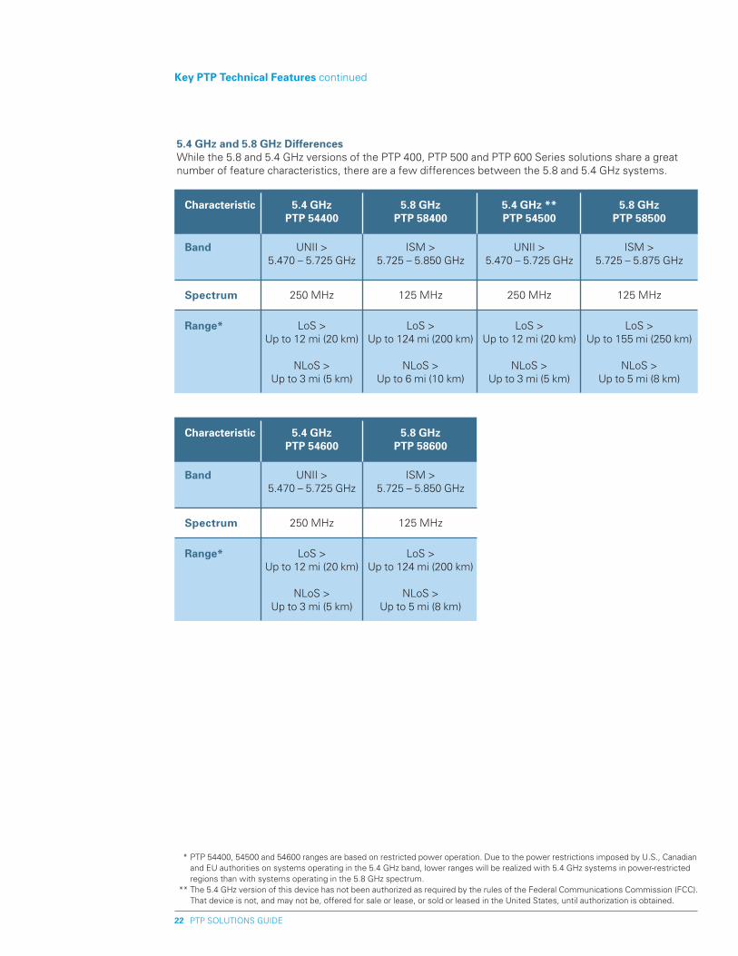
5.4 Ghz and 5.8 Ghz Differences While the 5.8 and 5.4 GHz versions of the PTP 400, PTP 500 and PTP 600 Series solutions share a great number of feature characteristics, there are a few differences between the 5.8 and 5.4 GHz systems.
Key pTp Technical Features continued
* PTP 54400, 54500 and 54600 ranges are based on restricted power operation. Due to the power restrictions imposed by U.S., Canadian and EU authorities on systems operating in the 5.4 GHz band, lower ranges will be realized with 5.4 GHz systems in power-restricted regions than with systems operating in the 5.8 GHz spectrum.
** The 5.4 GHz version of this device has not been authorized as required by the rules of the Federal Communications Commission (FCC). That device is not, and may not be, offered for sale or lease, or sold or leased in the United States, until authorization is obtained.
Characteristic
Band
Range*
Spectrum
5.4 Ghz pTp 54600
UNII > 5.470 – 5.725 GHz
LoS > Up to 12 mi (20 km)
NLoS >
Up to 3 mi (5 km)
250 MHz
5.8 Ghz pTp 58600
ISM > 5.725 – 5.850 GHz
LoS > Up to 124 mi (200 km)
NLoS > Up to 5 mi (8 km)
125 MHz
PTP SOLUTIONS GUIDE�3
pTp 400 Series Bridges – Aggregate Ethernet Throughput Rates
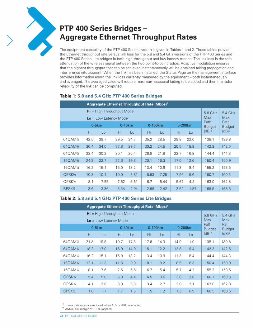
The equipment capability of the PTP 400 Series system is given in Tables 1 and 2. These tables provide the Ethernet throughput rate versus link loss for the 5.8 and 5.4 GHz versions of the PTP 400 Series and the PTP 400 Series Lite bridges in both high-throughput and low-latency modes. The link loss is the total attenuation of the wireless signal between the two point-to-point radios. Adaptive modulation ensures that the highest throughput that can be achieved instantaneously will be obtained taking propagation and interference into account. When the link has been installed, the Status Page on the management interface provides information about the link loss currently measured by the equipment – both instantaneously and averaged. The averaged value will require maximum seasonal fading to be added and then the radio reliability of the link can be computed.
Table 1: 5.8 and 5.4 Ghz pTp 400 Series Bridges
5.8 GHz Max Path Budget (dB)2
5.4 GHz Max Path Budget (dB)2
Aggregate Ethernet Throughput Rate (Mbps)1
hi = High Throughput Mode
Lo = Low Latency Mode
0-5km 0-40km 0-100km 0-200km
Hi Lo Hi Lo Hi Lo Hi Lo
64QAM7/8 42.5 39.7 39.5 34.7 35.2 28.5 29.8 22.0 138.1 139.8
64QAM3/4 36.4 34.0 33.8 29.7 30.2 24.5 25.5 18.9 142.3 142.5
64QAM2/3 32.4 30.2 30.1 26.4 26.8 21.8 22.7 16.8 144.4 144.3
16QAM3/4 24.3 22.7 22.6 19.8 20.1 16.3 17.0 12.6 150.4 150.9
16QAM1/2 16.2 15.1 15.0 13.2 13.4 10.9 11.3 8.4 155.2 153.5
QPSK2/3 10.8 10.1 10.0 8.81 8.93 7.25 7.56 5.6 160.7 160.3
QPSK1/2 8.1 7.55 7.52 6.61 6.7 5.44 5.67 4.2 163.0 162.8
BPSK1/2 3.6 3.36 3.34 2.94 2.98 2.42 2.52 1.87 168.5 168.6
Table �: 5.8 and 5.4 Ghz pTp 400 Series Lite Bridges
5.8 GHz Max Path Budget (dB)2
5.4 GHz Max Path Budget (dB)2
1 These data rates are reduced when AES or ARQ is enabled. 2 AMOD link margin of 1.5 dB applied.
Aggregate Ethernet Throughput Rate (Mbps)1
hi = High Throughput Mode
Lo = Low Latency Mode
0-5km 0-40km 0-100km 0-200km
Hi Lo Hi Lo Hi Lo Hi Lo
64QAM7/8 21.3 19.8 19.7 17.3 17.6 14.3 14.9 11.0 138.1 139.8
64QAM3/4 18.2 17.0 16.9 14.9 15.1 12.2 12.8 9.4 142.3 142.5
64QAM2/3 16.2 15.1 15.0 13.2 13.4 10.9 11.3 8.4 144.4 144.3
16QAM3/4 12.1 11.3 11.3 9.9 10.1 8.2 8.5 6.3 150.4 150.9
16QAM1/2 8.1 7.6 7.5 6.6 6.7 5.4 5.7 4.2 155.2 153.5
QPSK2/3 5.4 5.0 5.0 4.4 4.5 3.6 3.8 2.8 160.7 160.3
QPSK1/2 4.1 3.8 3.8 3.3 3.4 2.7 2.8 2.1 163.0 162.8
BPSK1/2 1.8 1.7 1.7 1.5 1.5 1.2 1.3 0.9 168.5 168.6
PTP SOLUTIONS GUIDE�4
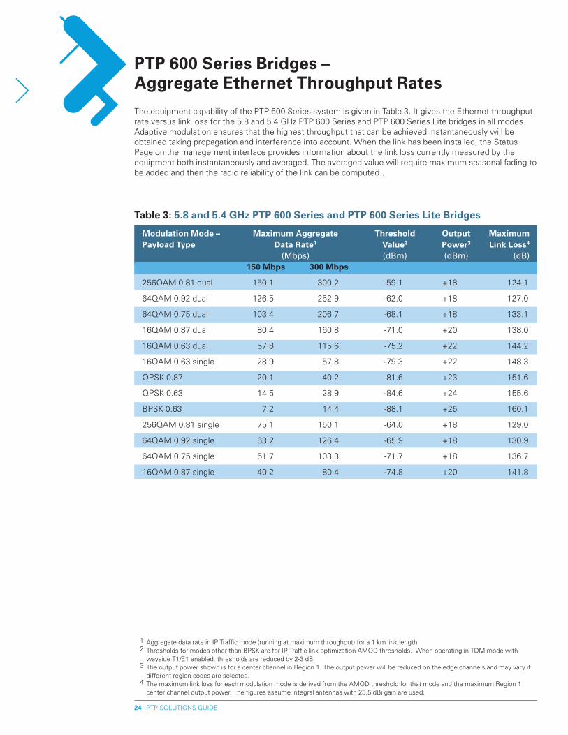
pTp 600 Series Bridges – Aggregate Ethernet Throughput Rates
1 Aggregate data rate in IP Traffic mode (running at maximum throughput) for a 1 km link length 2 Thresholds for modes other than BPSK are for IP Traffic link-optimization AMOD thresholds. When operating in TDM mode with
wayside T1/E1 enabled, thresholds are reduced by 2-3 dB. 3 The output power shown is for a center channel in Region 1. The output power will be reduced on the edge channels and may vary if
different region codes are selected. 4 The maximum link loss for each modulation mode is derived from the AMOD threshold for that mode and the maximum Region 1
center channel output power. The figures assume integral antennas with 23.5 dBi gain are used.
Table 3: 5.8 and 5.4 Ghz pTp 600 Series and pTp 600 Series Lite Bridges
Modulation Mode – Maximum Aggregate Threshold Output Maximum payload Type Data Rate1 Value� power3 Link Loss4
(Mbps) (dBm) (dBm) (dB) 150 Mbps 300 Mbps
256QAM 0.81 dual 150.1 300.2 -59.1 +18 124.1
64QAM 0.92 dual 126.5 252.9 -62.0 +18 127.0
64QAM 0.75 dual 103.4 206.7 -68.1 +18 133.1
16QAM 0.87 dual 80.4 160.8 -71.0 +20 138.0
16QAM 0.63 dual 57.8 115.6 -75.2 +22 144.2
16QAM 0.63 single 28.9 57.8 -79.3 +22 148.3
QPSK 0.87 20.1 40.2 -81.6 +23 151.6
QPSK 0.63 14.5 28.9 -84.6 +24 155.6
BPSK 0.63 7.2 14.4 -88.1 +25 160.1
256QAM 0.81 single 75.1 150.1 -64.0 +18 129.0
64QAM 0.92 single 63.2 126.4 -65.9 +18 130.9
64QAM 0.75 single 51.7 103.3 -71.7 +18 136.7
16QAM 0.87 single 40.2 80.4 -74.8 +20 141.8
The equipment capability of the PTP 600 Series system is given in Table 3. It gives the Ethernet throughput rate versus link loss for the 5.8 and 5.4 GHz PTP 600 Series and PTP 600 Series Lite bridges in all modes. Adaptive modulation ensures that the highest throughput that can be achieved instantaneously will be obtained taking propagation and interference into account. When the link has been installed, the Status Page on the management interface provides information about the link loss currently measured by the equipment both instantaneously and averaged. The averaged value will require maximum seasonal fading to be added and then the radio reliability of the link can be computed..
PTP SOLUTIONS GUIDE�5
Although Motorola’s PTP 400, PTP 500 and PTP 600 Series radios are designed to withstand extreme conditions, they are often mounted on high towers, frequently with external antennas, making the radios prime targets for lightning strikes. The Motorola wi4 Fixed Point-to-Point Lightning Protection Unit (PTP-LPU) is designed to protect a Motorola PTP radio, excluding the PTP 100 Series radio, from the harmful effects of power surges induced in the cables by nearby lightning strikes. By grounding the power surges before they can harm the units, the Motorola PTP-LPU gives PTP radios the best protection from the harmful effects of lightning, although 100% protection is neither implied nor possible.
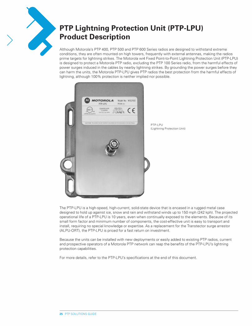
pTp Lightning protection Unit (pTp-LpU) product Description
The PTP-LPU is a high-speed, high-current, solid-state device that is encased in a rugged metal case designed to hold up against ice, snow and rain and withstand winds up to 150 mph (242 kph). The projected operational life of a PTP-LPU is 10 years, even when continually exposed to the elements. Because of its small form factor and minimum number of components, the cost-effective unit is easy to transport and install, requiring no special knowledge or expertise. As a replacement for the Transtector surge arrestor (ALPU-ORT), the PTP-LPU is priced for a fast return on investment.
Because the units can be installed with new deployments or easily added to existing PTP radios, current and prospective operators of a Motorola PTP network can reap the benefits of the PTP-LPU’s lightning protection capabilities.
For more details, refer to the PTP-LPU’s specifications at the end of this document.
PTP-LPU(Lightning Protection Unit)
PTP SOLUTIONS GUIDE�6
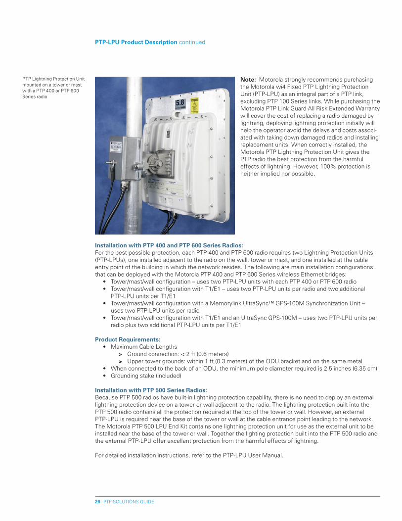
Installation with pTp 400 and pTp 600 Series Radios:For the best possible protection, each PTP 400 and PTP 600 radio requires two Lightning Protection Units (PTP-LPUs), one installed adjacent to the radio on the wall, tower or mast, and one installed at the cable entry point of the building in which the network resides. The following are main installation configurations that can be deployed with the Motorola PTP 400 and PTP 600 Series wireless Ethernet bridges: • Tower/mast/wall configuration – uses two PTP-LPU units with each PTP 400 or PTP 600 radio • Tower/mast/wall configuration with T1/E1 – uses two PTP-LPU units per radio and two additional
PTP-LPU units per T1/E1 • Tower/mast/wall configuration with a Memorylink UltraSync™ GPS-100M Synchronization Unit –
uses two PTP-LPU units per radio • Tower/mast/wall configuration with T1/E1 and an UltraSync GPS-100M – uses two PTP-LPU units per
radio plus two additional PTP-LPU units per T1/E1
product Requirements: • Maximum Cable Lengths > Ground connection: < 2 ft (0.6 meters) > Upper tower grounds: within 1 ft (0.3 meters) of the ODU bracket and on the same metal • When connected to the back of an ODU, the minimum pole diameter required is 2.5 inches (6.35 cm) • Grounding stake (included)
Installation with pTp 500 Series Radios:Because PTP 500 radios have built-in lightning protection capability, there is no need to deploy an external lightning protection device on a tower or wall adjacent to the radio. The lightning protection built into the PTP 500 radio contains all the protection required at the top of the tower or wall. However, an external PTP-LPU is required near the base of the tower or wall at the cable entrance point leading to the network. The Motorola PTP 500 LPU End Kit contains one lightning protection unit for use as the external unit to be installed near the base of the tower or wall. Together the lighting protection built into the PTP 500 radio and the external PTP-LPU offer excellent protection from the harmful effects of lightning.
For detailed installation instructions, refer to the PTP-LPU User Manual.
pTp-LpU product Description continued
PTP Lightning Protection Unit mounted on a tower or mast with a PTP 400 or PTP 600 Series radio
Note: Motorola strongly recommends purchasing the Motorola wi4 Fixed PTP Lightning Protection Unit (PTP-LPU) as an integral part of a PTP link, excluding PTP 100 Series links. While purchasing the Motorola PTP Link Guard All Risk Extended Warranty will cover the cost of replacing a radio damaged by lightning, deploying lightning protection initially will help the operator avoid the delays and costs associ-ated with taking down damaged radios and installing replacement units. When correctly installed, the Motorola PTP Lightning Protection Unit gives the PTP radio the best protection from the harmful effects of lightning. However, 100% protection is neither implied nor possible.
PTP SOLUTIONS GUIDE�7
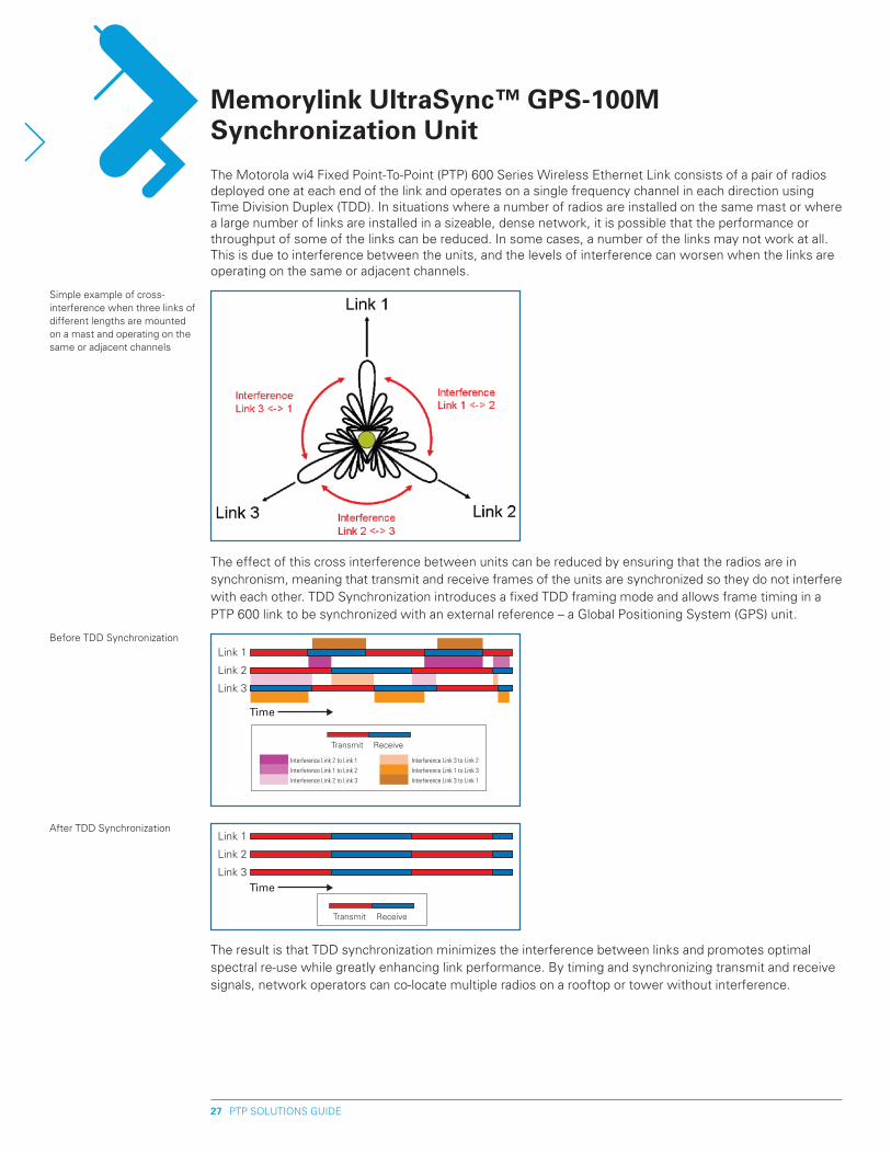
The Motorola wi4 Fixed Point-To-Point (PTP) 600 Series Wireless Ethernet Link consists of a pair of radios deployed one at each end of the link and operates on a single frequency channel in each direction using Time Division Duplex (TDD). In situations where a number of radios are installed on the same mast or where a large number of links are installed in a sizeable, dense network, it is possible that the performance or throughput of some of the links can be reduced. In some cases, a number of the links may not work at all. This is due to interference between the units, and the levels of interference can worsen when the links are operating on the same or adjacent channels.
Memorylink UltraSync™ GpS-100M Synchronization Unit
The effect of this cross interference between units can be reduced by ensuring that the radios are in synchronism, meaning that transmit and receive frames of the units are synchronized so they do not interfere with each other. TDD Synchronization introduces a fixed TDD framing mode and allows frame timing in a PTP 600 link to be synchronized with an external reference – a Global Positioning System (GPS) unit.
The result is that TDD synchronization minimizes the interference between links and promotes optimal spectral re-use while greatly enhancing link performance. By timing and synchronizing transmit and receive signals, network operators can co-locate multiple radios on a rooftop or tower without interference.
Simple example of cross-interference when three links of different lengths are mounted on a mast and operating on the same or adjacent channels
Link 1
Link 3
Interference Link 3 to Link 2
Interference Link 1 to Link 3
Interference Link 3 to Link 1
Interference Link 2 to Link 1
Interference Link 1 to Link 2
Interference Link 2 to Link 3
Link 2
Time
Transmit Receive
Link 1
Link 3Time
Link 2
Transmit Receive
Before TDD Synchronization
After TDD Synchronization
The reliable UltraSync GPS-100M generates a time-reference signal that originates from the atomic clocks on the GPS satellites that orbit the earth. The units come pre-wired for new systems and can be retrofitted for existing PTP 600 Series links.
UltraSync GpS-100M Features: • Integral GPS receiver – 12 channel • Passes 1000 Base-T protocol • Supports Ethernet cable lengths of up to 330 feet (100 meters) from the PTP 600 PIDU Plus to the
UltraSync GPS-100M Eth1/PWR port • Robust enclosure weighing approximately 23 ounces (650 grams) • Small footprint – 5.92” (150 mm) height, 3.95” (100 mm) width and 2.79” (71 mm) depth • Includes internally mounted GPS antenna, mounting bracket, screws, Ethernet cables and cable
glands for waterproof ingress/egress • Connects via RJ-45 connector to PTP 600 Series radios equipped with a sync port • Operates at temperatures to – 40°F to +140°F (-40°C to +60°C), even in high humidity
OrderingThe Memorylink UltraSync GPS-100M can be ordered directly from Motorola under the following part number and product description:
WB3001 – Memorylink UltraSync GPS-100M for PTP 600
PTP SOLUTIONS GUIDE�8
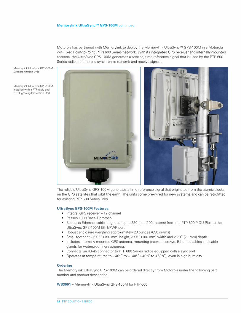
Motorola has partnered with Memorylink to deploy the Memorylink UltraSync™ GPS-100M in a Motorola wi4 Fixed Point-to-Point (PTP) 600 Series network. With its integrated GPS receiver and internally-mounted antenna, the UltraSync GPS-100M generates a precise, time-reference signal that is used by the PTP 600 Series radios to time and synchronize transmit and receive signals.
Memorylink UltraSync™ GpS-100M continued
Memorylink UltraSync GPS-100M Synchronization Unit
Memorylink UltraSync GPS-100M installed with a PTP radio and PTP Lightning Protection Unit
PTP SOLUTIONS GUIDE�9
pTp Link Estimator for pTp 400 and pTp 600 Series Links
The PTP 400 and PTP 600 Series Link Estimator Tool is an Excel spreadsheet that allows customers to determine link performance characteristics prior to purchase, given certain assumptions about geography, distance, antenna height, transmit power and other factors. The PTP Link Estimator Tool can be down-loaded free at www.motorola.com/ptp.
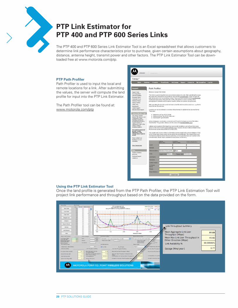
Using the pTp Link Estimator ToolOnce the land profile is generated from the PTP Path Profiler, the PTP Link Estimation Tool will project link performance and throughput based on the data provided on the form.
pTp path profilerPath Profiler is used to input the local and remote locations for a link. After submitting the values, the server will compute the land profile for input into the PTP Link Estimator.
The Path Profiler tool can be found at: www.motorola.com/ptp
PTP SOLUTIONS GUIDE30
The benefit is that you can optimize a link before deployment by changing input data to see the effect on performance and throughput. For example, if a link calculation indicates low throughput, then a number of factors can be changed to see the improvement on link performance.
Operating range and data throughput is dependent on several factors, including: • Path Length • Antenna height on local or remote site • Obstructions (height and distance) • Antenna type - Integrated or Connectorized (with external antenna to provide additional system gain) • Connectorized antenna options (Dual or single pole Flat Panels from 1’ to 2’, Parabolic from 2’ to 6’) • Location of the link – site elevation and terrain • Radio – select PTP 400 or PTP 600 to determine performance impact
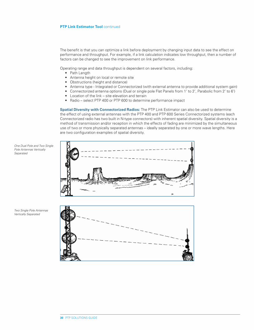
Spatial Diversity with Connectorized Radios: The PTP Link Estimator can also be used to determine the effect of using external antennas with the PTP 400 and PTP 600 Series Connectorized systems (each Connectorized radio has two built in N-type connectors) with inherent spatial diversity. Spatial diversity is a method of transmission and/or reception in which the effects of fading are minimized by the simultaneous use of two or more physically separated antennas – ideally separated by one or more wave lengths. Here are two configuration examples of spatial diversity.
pTp Link Estimator Tool continued
One Dual Pole and Two Single Pole Antennas Vertically Separated
Two Single Pole Antennas Vertically Separated
PTP SOLUTIONS GUIDE31
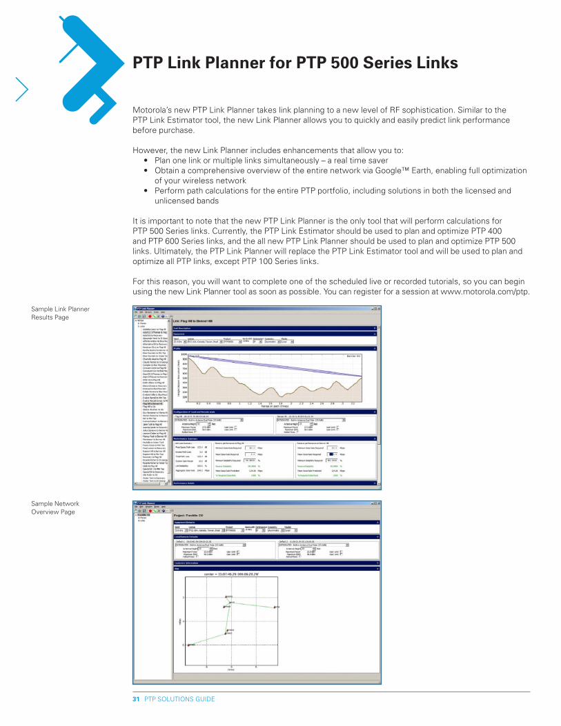
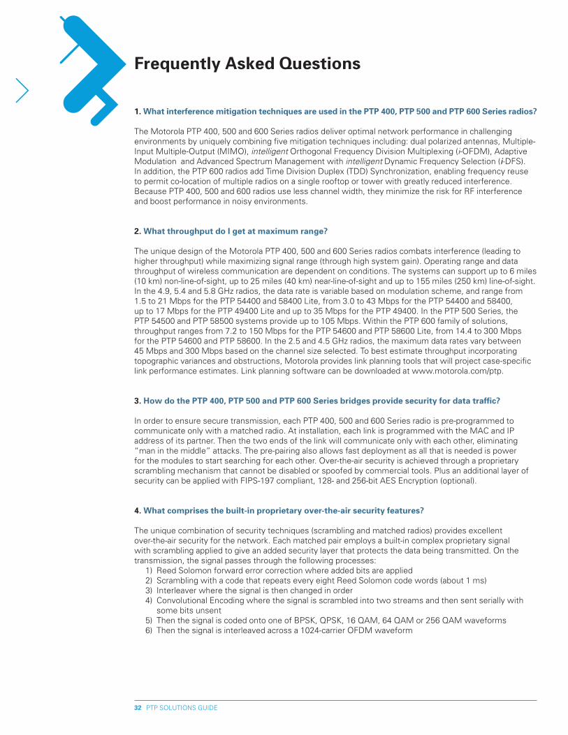
Motorola’s new PTP Link Planner takes link planning to a new level of RF sophistication. Similar to the PTP Link Estimator tool, the new Link Planner allows you to quickly and easily predict link performance before purchase.
However, the new Link Planner includes enhancements that allow you to: • Plan one link or multiple links simultaneously – a real time saver • Obtain a comprehensive overview of the entire network via Google™ Earth, enabling full optimization
of your wireless network • Perform path calculations for the entire PTP portfolio, including solutions in both the licensed and
unlicensed bands
It is important to note that the new PTP Link Planner is the only tool that will perform calculations for PTP 500 Series links. Currently, the PTP Link Estimator should be used to plan and optimize PTP 400 and PTP 600 Series links, and the all new PTP Link Planner should be used to plan and optimize PTP 500 links. Ultimately, the PTP Link Planner will replace the PTP Link Estimator tool and will be used to plan and optimize all PTP links, except PTP 100 Series links.
For this reason, you will want to complete one of the scheduled live or recorded tutorials, so you can begin using the new Link Planner tool as soon as possible. You can register for a session at www.motorola.com/ptp.
pTp Link planner for pTp 500 Series Links
Sample Link Planner Results Page
Sample Network Overview Page
PTP SOLUTIONS GUIDE3�
Frequently Asked Questions
1. What interference mitigation techniques are used in the pTp 400, pTp 500 and pTp 600 Series radios?
The Motorola PTP 400, 500 and 600 Series radios deliver optimal network performance in challenging environments by uniquely combining five mitigation techniques including: dual polarized antennas, Multiple-Input Multiple-Output (MIMO), intelligent Orthogonal Frequency Division Multiplexing (i-OFDM), Adaptive Modulation and Advanced Spectrum Management with intelligent Dynamic Frequency Selection (i-DFS). In addition, the PTP 600 radios add Time Division Duplex (TDD) Synchronization, enabling frequency reuse to permit co-location of multiple radios on a single rooftop or tower with greatly reduced interference. Because PTP 400, 500 and 600 radios use less channel width, they minimize the risk for RF interference and boost performance in noisy environments.
�. What throughput do I get at maximum range?
The unique design of the Motorola PTP 400, 500 and 600 Series radios combats interference (leading to higher throughput) while maximizing signal range (through high system gain). Operating range and data throughput of wireless communication are dependent on conditions. The systems can support up to 6 miles (10 km) non-line-of-sight, up to 25 miles (40 km) near-line-of-sight and up to 155 miles (250 km) line-of-sight. In the 4.9, 5.4 and 5.8 GHz radios, the data rate is variable based on modulation scheme, and range from 1.5 to 21 Mbps for the PTP 54400 and 58400 Lite, from 3.0 to 43 Mbps for the PTP 54400 and 58400, up to 17 Mbps for the PTP 49400 Lite and up to 35 Mbps for the PTP 49400. In the PTP 500 Series, the PTP 54500 and PTP 58500 systems provide up to 105 Mbps. Within the PTP 600 family of solutions, throughput ranges from 7.2 to 150 Mbps for the PTP 54600 and PTP 58600 Lite, from 14.4 to 300 Mbps for the PTP 54600 and PTP 58600. In the 2.5 and 4.5 GHz radios, the maximum data rates vary between 45 Mbps and 300 Mbps based on the channel size selected. To best estimate throughput incorporating topographic variances and obstructions, Motorola provides link planning tools that will project case-specific link performance estimates. Link planning software can be downloaded at www.motorola.com/ptp.
3. how do the pTp 400, pTp 500 and pTp 600 Series bridges provide security for data traffic?
In order to ensure secure transmission, each PTP 400, 500 and 600 Series radio is pre-programmed to communicate only with a matched radio. At installation, each link is programmed with the MAC and IP address of its partner. Then the two ends of the link will communicate only with each other, eliminating “man in the middle” attacks. The pre-pairing also allows fast deployment as all that is needed is power for the modules to start searching for each other. Over-the-air security is achieved through a proprietary scrambling mechanism that cannot be disabled or spoofed by commercial tools. Plus an additional layer of security can be applied with FIPS-197 compliant, 128- and 256-bit AES Encryption (optional).
4. What comprises the built-in proprietary over-the-air security features?
The unique combination of security techniques (scrambling and matched radios) provides excellent over-the-air security for the network. Each matched pair employs a built-in complex proprietary signal with scrambling applied to give an added security layer that protects the data being transmitted. On the transmission, the signal passes through the following processes: 1) Reed Solomon forward error correction where added bits are applied 2) Scrambling with a code that repeats every eight Reed Solomon code words (about 1 ms) 3) Interleaver where the signal is then changed in order 4) Convolutional Encoding where the signal is scrambled into two streams and then sent serially with
some bits unsent 5) Then the signal is coded onto one of BPSK, QPSK, 16 QAM, 64 QAM or 256 QAM waveforms 6) Then the signal is interleaved across a 1024-carrier OFDM waveform
PTP SOLUTIONS GUIDE33
5. What security measures should be used along with the built-in over-the-air security?
In addition to the scrambling and matched-radio security included with all PTP 400, PTP 500 and PTP 600 Series radios, FIPS-197 compliant, 128-bit or 256-bit AES Encryption can be added as an option to meet specific security requirements. Motorola also encourages encryption of data before it is transmitted by using the security measures built into routers, network devices and web sites in order to ensure end-to-end protection of data.
6. Are the pTp 400, pTp 500 and pTp 600 Series radios 80�.11a devices?
The PTP 400, 500 and 600 Series bridges use different encoding and radio transmission systems than 802.11a. In areas where 802.11a systems are operating, they will detect the 802.11a radio signals and choose a clear channel away from any interference.
7. Will the pTp 400, pTp 500 and pTp 600 Series radios interfere with my Canopy® access network?
Flexibility is a key value driver of Motorola solutions. The PTP 400, 500 and 600 Series systems have been designed to interoperate with other Canopy AP clusters operating in the same frequency band. There are certain considerations that network operators must make during installation, including frequency allocation, vertical separation and angular direction of the modules. Refer to the User Guide for co-location information.
8. how do pTp 400, pTp 500 and pTp 600 bridges avoid interference from other devices nearby?
At initialization, the systems monitor the available frequency channels to find a channel that is clear of interference. In operation each radio continuously monitors the spectrum (sampling the band up to 400 times a second). When interference is encountered, the radio automatically switches to the clearest channel.
9. When do I use the pTp 400, pTp 500 and pTp 600 Series solutions?
PTP 400, 500 and 600 Series point-to-point wireless Ethernet bridges have been developed to enable network design that meets the needs of network users. Motorola has expertise that can help develop a profile of the current and estimated future demand of the network to provide sufficient capacity to meet service demands. Even in the most challenging environments, the unique combination of innovative technologies enables operators to achieve a reliable and high-throughput link for a wide variety of applications, including: • Backhaul to connect clusters of users to the backbone without wires • Long-distance connectivity to traverse geography (e.g., open terrain, water, etc.) without relays • Non-line-of-sight (NLoS) or near-line-of-sight (nLoS) performance where other solutions often cannot
make the connection • Spectral efficiency to place more links at hub-sites without creating interference • Redundancy and additional capacity for 6 GHz networks • Cost-effective connectivity between buildings • Video surveillance extensions beyond existing fiber/coax wired infrastructures • Cost-effective redundancy to back up wire-line circuits • Enterprise voice and data connectivity • Disaster recovery and temporary deployments for activities such as tactical military operations,
emergency services, security and surveillance, and short-term entertainment and sporting events • Bandwidth-intensive communications such as distance learning, telemedicine, streaming video and
multimedia • U.S. Federal and NATO uses such as battlefield communications, tactical military operations, border
security and video surveillance
FAQs continued
PTP SOLUTIONS GUIDE34
FAQs continued
10. What are the differences between the pTp 400, pTp 500 and pTp 600 Series power over Ethernet?
PTP 400 and PTP 500 Series radios support 100 BaseT while PTP 600 Series radios support 100/1000 BaseT. PTP 400 bridges are powered via two pairs of the Ethernet drop cable; the primary power is supplied on Pin 8 (Pin 7 return) while supplementary power for the longer cable runs is supplied on Pin 5 (Pin 4 Return). The supplementary pair is also used for ODU signaling. PTP 500 and PTP 600 bridges are powered via four data pairs of the Ethernet drop cable.
11. Can I source and use my own poE adapter with pTp 400, pTp 500 and pTp 600 Series bridges?
No. PTP 400, 500 and 600 Series systems use a non-standard PoE configuration, and failure to use each system’s powered indoor unit (PIDU Plus) could result in equipment damage, will invalidate the safety certification and may cause a safety hazard. Note: The Motorola Canopy® CMM should not be used to power PTP 400, 500 and 600 Series radios.
1�. how do pTp 400, pTp 500 and pTp 600 Series bridges integrate into my data network?
The system acts as a transparent bridge between two segments of your network. In this sense, each point-to-point wireless bridge can be treated as a virtual wired connection between the two buildings. A PTP 400, 500 or 600 Series system forwards 802.3 Ethernet packets destined for the other part of the network and filters packets that it does not need to forward. The system is transparent to higher-level management systems such as VLANs and Spanning Tree. In addition, the wi4 Fixed PTP 400, PTP 500 and PTP 600 Series systems integrate with Motorola’s Canopy Point-to-Multipoint and MOTOMESH networks.
13. Can I use Apple Macintosh OS x to control and monitor a pTp 400, pTp 500 and pTp 600 Series radio?
Yes, but there are some restrictions. Mozilla 1.6 or higher is recommended. There are some issues with Internet Explorer 5.2(IE) and Safari, which could mislead the user.
14. What is unique about the pTp 400, pTp 500 and pTp 600 Series radios?
There are many unique features built-in to the hardware and software such as Multiple-Input Multiple-Output (MIMO), intelligent OFDM, intelligent Dynamic Frequency Selection, Dual Polarized antennas and Adaptive Modulation. The radios offer the highest system gain in their class through high-sensitivity antennas for improved signal recovery. The radios also feature a software-defined system that operates on ultra-fast digital signal processors that are controlled by firmware, giving the ability to download new firmware when enhancements become available. The systems have a built-in web server for advanced management capabilities, including detailed radio signal diagnostics.
15. What is Multiple-Input Multiple-Output (MIMO)?
PTP 400, 500 and 600 Series Series radios radiate multiple beams from their dual polarized antennas – the effect of which is to significantly protect against fading and to radically increase the probability that the receiver will decode a usable signal in the face of multi-path and interference conditions. The effects of MIMO combined with intelligent OFDM provide a best-in-class link budget with high reliability in LoS, nLoS and NLoS environments.
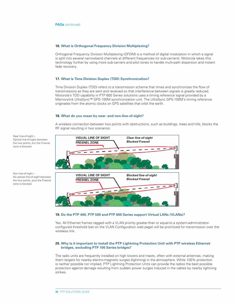
PTP SOLUTIONS GUIDE35
FAQs continued
16. What is Orthogonal Frequency Division Multiplexing?
Orthogonal Frequency Division Multiplexing (OFDM) is a method of digital modulation in which a signal is split into several narrowband channels at different frequencies (or sub-carriers). Motorola takes this technology further by using more sub-carriers and pilot tones to handle multi-path dispersion and instant fade recovery.
17. What is Time Division Duplex (TDD) Synchronization?
Time Division Duplex (TDD) refers to a transmission scheme that times and synchronizes the flow of transmissions as they are sent and received so that interference between signals is greatly reduced. Motorola’s TDD capability in PTP 600 Series solutions uses a timing reference signal provided by a Memorylink UltraSync™ GPS-100M synchronization unit. The UltraSync GPS-100M’s timing reference originates from the atomic clocks on GPS satellites that orbit the earth.
18. What do you mean by near- and non-line-of-sight?
A wireless connection between two points with obstructions, such as buildings, trees and hills, blocks the RF signal resulting in two scenarios:
19. Do the pTp 400, pTp 500 and pTp 600 Series support Virtual LANs (VLANs)?
Yes. All Ethernet frames tagged with a VLAN priority greater-than or equal-to a system-administrator- configured threshold (set on the VLAN Configuration web page) will be prioritized for transmission over the wireless link.
�0. Why is it important to install the pTp Lightning protection Unit with pTp wireless Ethernet bridges, excluding pTp 100 Series bridges?
The radio units are frequently installed on high towers and masts, often with external antennas, making them targets for nearby electro-magnetic surges (lightning) in the atmosphere. While 100% protection is neither possible nor implied, PTP Lightning Protection Units can provide the radios the best possible protection against damage resulting from sudden power surges induced in the cables by nearby lightning strikes.
VISUAL LINE OF SIGhT
FRESNEL ZONE
Clear line-of-sightBlocked Fresnel
Near line-of-sight – Optical line-of-sight between the two points, but the Fresnel zone is blocked
VISUAL LINE OF SIGhTFRESNEL ZONE
Blocked line-of-sightBlocked Fresnel
Non line-of-sight – No optical line-of-sight between the two points, plus the Fresnel zone is blocked.
PTP SOLUTIONS GUIDE36
�1. Doesn’t my Link Guard All Risk Extended Warranty cover lightning damage to my pTp radios?
Yes, the Link Guard All Risk Extended Warranty does cover the cost of replacement for a damaged PTP radio, excluding PTP 100 Series radios, in the event of a lightning strike. However, because the PTP-LPU can prevent the damage from occurring, you can eliminate the cost of taking down the damaged unit and installing the replacement unit, plus the downtime between the time the radio was damaged and when the replacement unit is installed. In addition, the attractive price point of the PTP-LPU means a fast return on investment, especially when you factor in higher service availability.
��. Why does each pTp 400 or pTp 600 Series radio require two Lightning protection Units?
Each PTP 400 and PTP 600 radio requires one PTP-LPU installed near the radio on the wall, tower or mast, and one PTP-LPU installed at the cable entry point of the building in which the network resides. The PTP-LPU’s two protection methods – line-to-line and line-to-ground – can stop a surge in power within 5 nanoseconds, ensuring maximum protection against damage. Each PTP-LPU End Kit includes two LPUs, the required installation hardware and cables (excluding the drop cable and connection to the user’s network). Two PTP-LPU End Kits are required for each PTP 400 and PTP 600 link.
�3. If I already have a Transtector Surge Arrestor, the ALpU-ORT, should I replace it?
If you already have Transtector ALPU-ORT units installed with your links and the units are working satisfactorily, you can continue to use the Transtector surge arrestors. However, as you add PTP links, excluding PTP 100 Series links, to your network, you should deploy those new units with PTP-LPUs. In addition, the PTP-LPU has an improved design which provides excellent grounding, ruggedness and ease of use with a projected 10-year lifespan. If your Transtector units have been in place for a significant length of time, you may want to replace the Transtector surge arrestors with the newer PTP-LPUs to benefit from the units’ advantages. PTP-LPUs can be added to existing deployments with relative ease.
FAQs continued
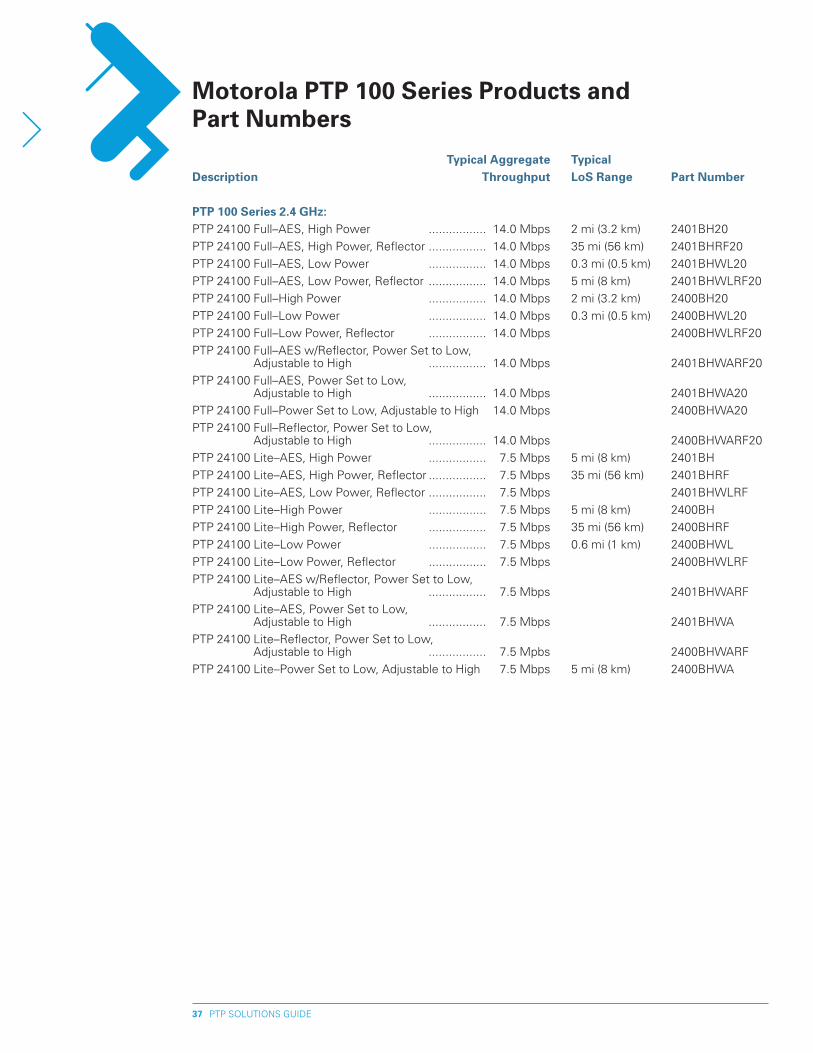
PTP SOLUTIONS GUIDE37
Typical Aggregate Typical Description Throughput LoS Range part Number
pTp 100 Series �.4 Ghz:PTP 24100 Full–AES, High Power ................. 14.0 Mbps 2 mi (3.2 km) 2401BH20
PTP 24100 Full–AES, High Power, Reflector ................. 14.0 Mbps 35 mi (56 km) 2401BHRF20
PTP 24100 Full–AES, Low Power ................. 14.0 Mbps 0.3 mi (0.5 km) 2401BHWL20
PTP 24100 Full–AES, Low Power, Reflector ................. 14.0 Mbps 5 mi (8 km) 2401BHWLRF20
PTP 24100 Full–High Power ................. 14.0 Mbps 2 mi (3.2 km) 2400BH20
PTP 24100 Full–Low Power ................. 14.0 Mbps 0.3 mi (0.5 km) 2400BHWL20
PTP 24100 Full–Low Power, Reflector ................. 14.0 Mbps 2400BHWLRF20
PTP 24100 Full–AES w/Reflector, Power Set to Low, Adjustable to High ................. 14.0 Mbps 2401BHWARF20
PTP 24100 Full–AES, Power Set to Low, Adjustable to High ................. 14.0 Mbps 2401BHWA20
PTP 24100 Full–Power Set to Low, Adjustable to High 14.0 Mbps 2400BHWA20
PTP 24100 Full–Reflector, Power Set to Low, Adjustable to High ................. 14.0 Mbps 2400BHWARF20
PTP 24100 Lite–AES, High Power ................. 7.5 Mbps 5 mi (8 km) 2401BH
PTP 24100 Lite–AES, High Power, Reflector ................. 7.5 Mbps 35 mi (56 km) 2401BHRF
PTP 24100 Lite–AES, Low Power, Reflector ................. 7.5 Mbps 2401BHWLRF
PTP 24100 Lite–High Power ................. 7.5 Mbps 5 mi (8 km) 2400BH
PTP 24100 Lite–High Power, Reflector ................. 7.5 Mbps 35 mi (56 km) 2400BHRF
PTP 24100 Lite–Low Power ................. 7.5 Mbps 0.6 mi (1 km) 2400BHWL
PTP 24100 Lite–Low Power, Reflector ................. 7.5 Mbps 2400BHWLRF
PTP 24100 Lite–AES w/Reflector, Power Set to Low, Adjustable to High ................. 7.5 Mbps 2401BHWARF
PTP 24100 Lite–AES, Power Set to Low, Adjustable to High ................. 7.5 Mbps 2401BHWA
PTP 24100 Lite–Reflector, Power Set to Low, Adjustable to High ................. 7.5 Mpbs 2400BHWARF
PTP 24100 Lite–Power Set to Low, Adjustable to High 7.5 Mbps 5 mi (8 km) 2400BHWA
Motorola pTp 100 Series products and part Numbers
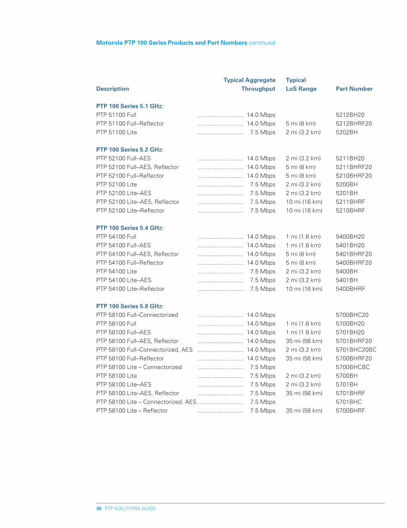
PTP SOLUTIONS GUIDE38
Typical Aggregate Typical Description Throughput LoS Range part Number
pTp 100 Series 5.1 Ghz:PTP 51100 Full ........................... 14.0 Mbps 5212BH20
PTP 51100 Full–Reflector ........................... 14.0 Mbps 5 mi (8 km) 5212BHRF20
PTP 51100 Lite ........................... 7.5 Mbps 2 mi (3.2 km) 5202BH
pTp 100 Series 5.� Ghz:PTP 52100 Full–AES ........................... 14.0 Mbps 2 mi (3.2 km) 5211BH20
PTP 52100 Full–AES, Reflector ........................... 14.0 Mbps 5 mi (8 km) 5211BHRF20
PTP 52100 Full–Reflector ........................... 14.0 Mbps 5 mi (8 km) 5210BHRF20
PTP 52100 Lite ........................... 7.5 Mbps 2 mi (3.2 km) 5200BH
PTP 52100 Lite–AES ........................... 7.5 Mbps 2 mi (3.2 km) 5201BH
PTP 52100 Lite–AES, Reflector ........................... 7.5 Mbps 10 mi (16 km) 5211BHRF
PTP 52100 Lite–Reflector ........................... 7.5 Mbps 10 mi (16 km) 5210BHRF
pTp 100 Series 5.4 Ghz: PTP 54100 Full ........................... 14.0 Mbps 1 mi (1.6 km) 5400BH20
PTP 54100 Full–AES ........................... 14.0 Mbps 1 mi (1.6 km) 5401BH20
PTP 54100 Full–AES, Reflector ........................... 14.0 Mbps 5 mi (8 km) 5401BHRF20
PTP 54100 Full–Reflector ........................... 14.0 Mbps 5 mi (8 km) 5400BHRF20
PTP 54100 Lite ........................... 7.5 Mbps 2 mi (3.2 km) 5400BH
PTP 54100 Lite–AES ........................... 7.5 Mbps 2 mi (3.2 km) 5401BH
PTP 54100 Lite–Reflector ........................... 7.5 Mbps 10 mi (16 km) 5400BHRF
pTp 100 Series 5.8 Ghz:PTP 58100 Full–Connectorized ........................... 14.0 Mbps 5700BHC20
PTP 58100 Full ........................... 14.0 Mbps 1 mi (1.6 km) 5700BH20
PTP 58100 Full–AES ........................... 14.0 Mbps 1 mi (1.6 km) 5701BH20
PTP 58100 Full–AES, Reflector ........................... 14.0 Mbps 35 mi (56 km) 5701BHRF20
PTP 58100 Full–Connectorized, AES ........................... 14.0 Mbps 2 mi (3.2 km) 5701BHC20BC
PTP 58100 Full–Reflector ........................... 14.0 Mbps 35 mi (56 km) 5700BHRF20
PTP 58100 Lite – Connectorized ........................... 7.5 Mbps 5700BHCBC
PTP 58100 Lite ........................... 7.5 Mbps 2 mi (3.2 km) 5700BH
PTP 58100 Lite–AES ........................... 7.5 Mbps 2 mi (3.2 km) 5701BH
PTP 58100 Lite–AES, Reflector ........................... 7.5 Mbps 35 mi (56 km) 5701BHRF
PTP 58100 Lite – Connectorized, AES ........................... 7.5 Mbps 5701BHC
PTP 58100 Lite – Reflector ........................... 7.5 Mbps 35 mi (56 km) 5700BHRF
Motorola pTp 100 Series products and part Numbers continued
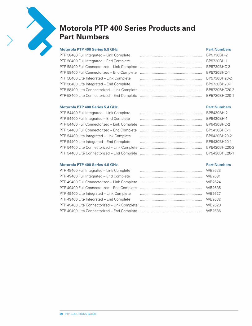
PTP SOLUTIONS GUIDE39
Motorola pTp 400 Series 5.8 Ghz part Numbers
PTP 58400 Full Integrated – Link Complete ........................................................... BP5730BH-2
PTP 58400 Full Integrated – End Complete ........................................................... BP5730BH-1
PTP 58400 Full Connectorized – Link Complete ........................................................... BP5730BHC-2
PTP 58400 Full Connectorized – End Complete ........................................................... BP5730BHC-1
PTP 58400 Lite Integrated – Link Complete ........................................................... BP5730BH20-2
PTP 58400 Lite Integrated – End Complete ........................................................... BP5730BH20-1
PTP 58400 Lite Connectorized – Link Complete ........................................................... BP5730BHC20-2
PTP 58400 Lite Connectorized – End Complete ........................................................... BP5730BHC20-1
Motorola pTp 400 Series 5.4 Ghz part Numbers
PTP 54400 Full Integrated – Link Complete ........................................................... BP5430BH-2
PTP 54400 Full Integrated – End Complete ........................................................... BP5430BH-1
PTP 54400 Full Connectorized – Link Complete ........................................................... BP5430BHC-2
PTP 54400 Full Connectorized – End Complete ........................................................... BP5430BHC-1
PTP 54400 Lite Integrated – Link Complete ........................................................... BP5430BH20-2
PTP 54400 Lite Integrated – End Complete ........................................................... BP5430BH20-1
PTP 54400 Lite Connectorized – Link Complete ........................................................... BP5430BHC20-2
PTP 54400 Lite Connectorized – End Complete ........................................................... BP5430BHC20-1
Motorola pTp 400 Series 4.9 Ghz part Numbers
PTP 49400 Full Integrated – Link Complete ........................................................... WB2623
PTP 49400 Full Integrated – End Complete ........................................................... WB2631
PTP 49400 Full Connectorized – Link Complete ........................................................... WB2624
PTP 49400 Full Connectorized – End Complete ........................................................... WB2635
PTP 49400 Lite Integrated – Link Complete ........................................................... WB2627
PTP 49400 Lite Integrated – End Complete ........................................................... WB2632
PTP 49400 Lite Connectorized – Link Complete ........................................................... WB2628
PTP 49400 Lite Connectorized – End Complete ........................................................... WB2636
Motorola pTp 400 Series products and part Numbers
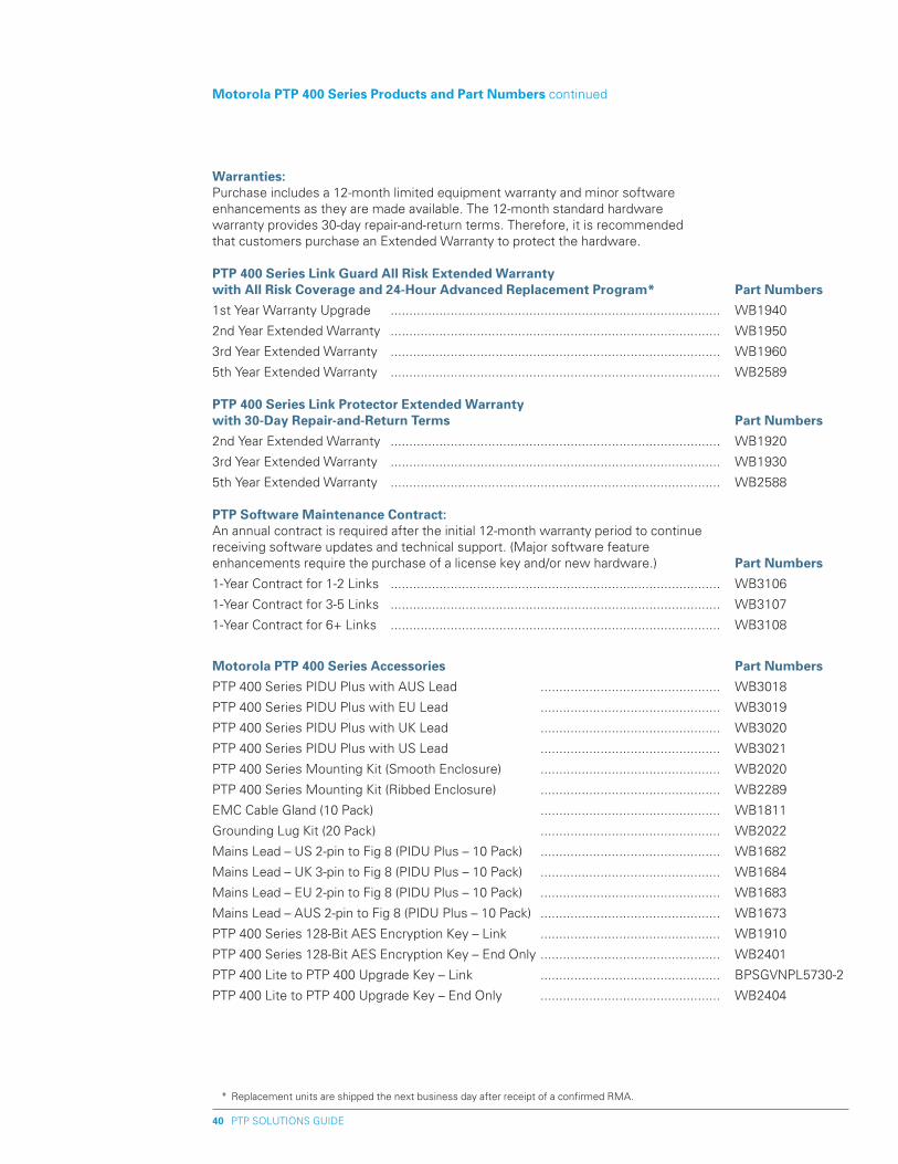
PTP SOLUTIONS GUIDE40
Warranties: Purchase includes a 12-month limited equipment warranty and minor software enhancements as they are made available. The 12-month standard hardware warranty provides 30-day repair-and-return terms. Therefore, it is recommended that customers purchase an Extended Warranty to protect the hardware.
pTp 400 Series Link Guard All Risk Extended Warranty with All Risk Coverage and �4-hour Advanced Replacement program* part Numbers
1st Year Warranty Upgrade ........................................................................................ WB1940
2nd Year Extended Warranty ........................................................................................ WB1950
3rd Year Extended Warranty ........................................................................................ WB1960
5th Year Extended Warranty ........................................................................................ WB2589
pTp 400 Series Link protector Extended Warranty with 30-Day Repair-and-Return Terms part Numbers
2nd Year Extended Warranty ........................................................................................ WB1920
3rd Year Extended Warranty ........................................................................................ WB1930
5th Year Extended Warranty ........................................................................................ WB2588
pTp Software Maintenance Contract: An annual contract is required after the initial 12-month warranty period to continue receiving software updates and technical support. (Major software feature enhancements require the purchase of a license key and/or new hardware.) part Numbers
1-Year Contract for 1-2 Links ........................................................................................ WB3106
1-Year Contract for 3-5 Links ........................................................................................ WB3107
1-Year Contract for 6+ Links ........................................................................................ WB3108
Motorola pTp 400 Series Accessories part Numbers
PTP 400 Series PIDU Plus with AUS Lead ................................................ WB3018
PTP 400 Series PIDU Plus with EU Lead ................................................ WB3019
PTP 400 Series PIDU Plus with UK Lead ................................................ WB3020
PTP 400 Series PIDU Plus with US Lead ................................................ WB3021
PTP 400 Series Mounting Kit (Smooth Enclosure) ................................................ WB2020
PTP 400 Series Mounting Kit (Ribbed Enclosure) ................................................ WB2289
EMC Cable Gland (10 Pack) ................................................ WB1811
Grounding Lug Kit (20 Pack) ................................................ WB2022
Mains Lead – US 2-pin to Fig 8 (PIDU Plus – 10 Pack) ................................................ WB1682
Mains Lead – UK 3-pin to Fig 8 (PIDU Plus – 10 Pack) ................................................ WB1684
Mains Lead – EU 2-pin to Fig 8 (PIDU Plus – 10 Pack) ................................................ WB1683
Mains Lead – AUS 2-pin to Fig 8 (PIDU Plus – 10 Pack) ................................................ WB1673
PTP 400 Series 128-Bit AES Encryption Key – Link ................................................ WB1910
PTP 400 Series 128-Bit AES Encryption Key – End Only ................................................ WB2401
PTP 400 Lite to PTP 400 Upgrade Key – Link ................................................ BPSGVNPL5730-2
PTP 400 Lite to PTP 400 Upgrade Key – End Only ................................................ WB2404
Motorola pTp 400 Series products and part Numbers continued
* Replacement units are shipped the next business day after receipt of a confirmed RMA.
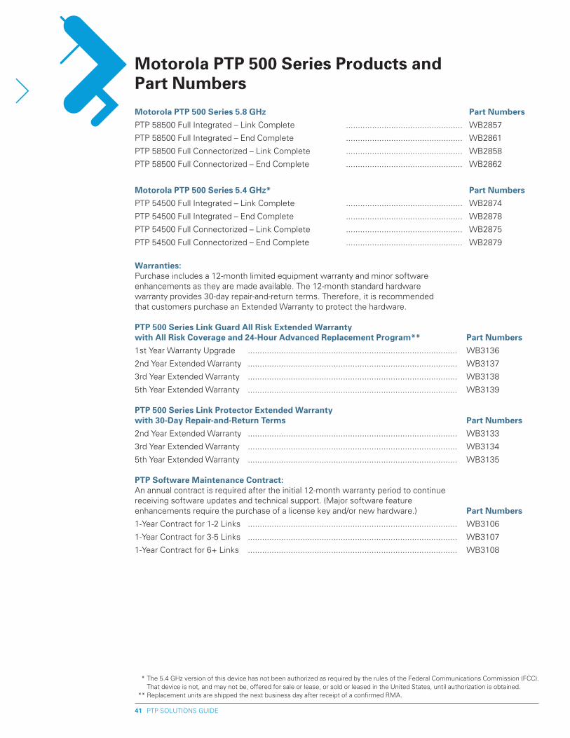
PTP SOLUTIONS GUIDE41
Motorola pTp 500 Series 5.8 Ghz part Numbers
PTP 58500 Full Integrated – Link Complete ................................................. WB2857
PTP 58500 Full Integrated – End Complete ................................................. WB2861
PTP 58500 Full Connectorized – Link Complete ................................................. WB2858
PTP 58500 Full Connectorized – End Complete ................................................. WB2862
Motorola pTp 500 Series 5.4 Ghz* part Numbers
PTP 54500 Full Integrated – Link Complete ................................................. WB2874
PTP 54500 Full Integrated – End Complete ................................................. WB2878
PTP 54500 Full Connectorized – Link Complete ................................................. WB2875
PTP 54500 Full Connectorized – End Complete ................................................. WB2879
Warranties: Purchase includes a 12-month limited equipment warranty and minor software enhancements as they are made available. The 12-month standard hardware warranty provides 30-day repair-and-return terms. Therefore, it is recommended that customers purchase an Extended Warranty to protect the hardware.
pTp 500 Series Link Guard All Risk Extended Warranty with All Risk Coverage and �4-hour Advanced Replacement program** part Numbers
1st Year Warranty Upgrade ........................................................................................ WB3136
2nd Year Extended Warranty ........................................................................................ WB3137
3rd Year Extended Warranty ........................................................................................ WB3138
5th Year Extended Warranty ........................................................................................ WB3139
pTp 500 Series Link protector Extended Warranty with 30-Day Repair-and-Return Terms part Numbers
2nd Year Extended Warranty ........................................................................................ WB3133
3rd Year Extended Warranty ........................................................................................ WB3134
5th Year Extended Warranty ........................................................................................ WB3135
pTp Software Maintenance Contract: An annual contract is required after the initial 12-month warranty period to continue receiving software updates and technical support. (Major software feature enhancements require the purchase of a license key and/or new hardware.) part Numbers
1-Year Contract for 1-2 Links ........................................................................................ WB3106
1-Year Contract for 3-5 Links ........................................................................................ WB3107
1-Year Contract for 6+ Links ........................................................................................ WB3108
Motorola pTp 500 Series products and part Numbers
* The 5.4 GHz version of this device has not been authorized as required by the rules of the Federal Communications Commission (FCC). That device is not, and may not be, offered for sale or lease, or sold or leased in the United States, until authorization is obtained.
** Replacement units are shipped the next business day after receipt of a confirmed RMA.
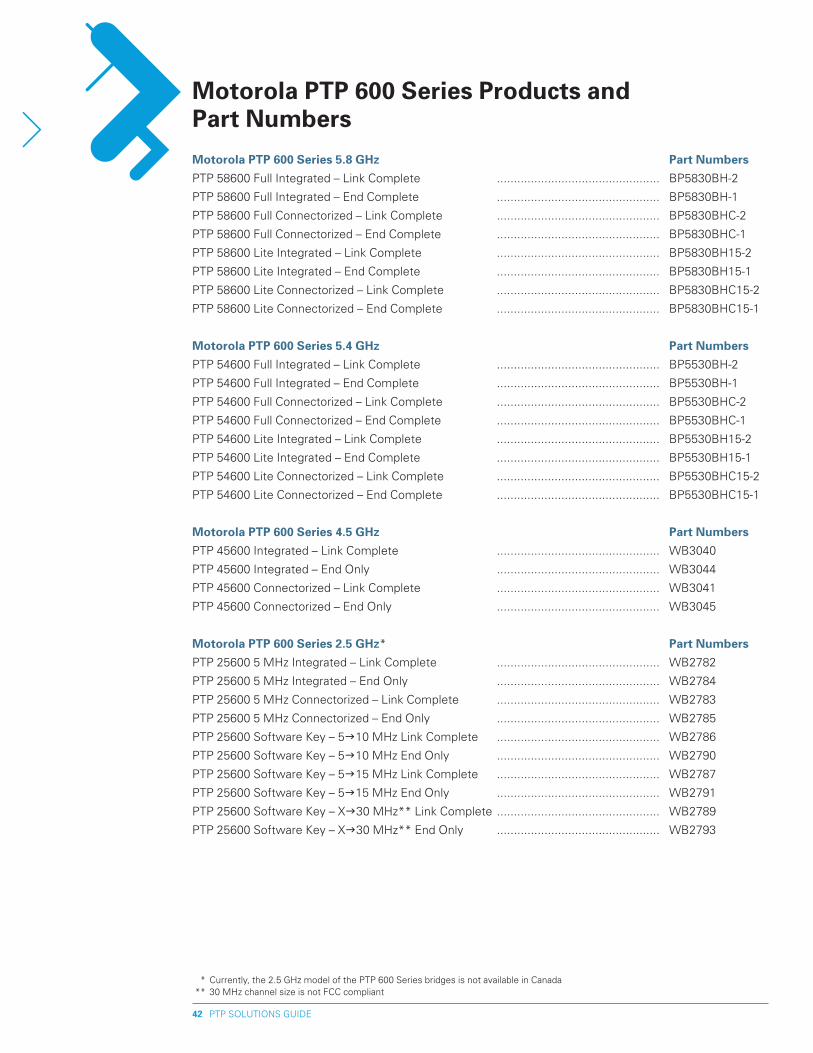
PTP SOLUTIONS GUIDE4�
Motorola pTp 600 Series 5.8 Ghz part Numbers
PTP 58600 Full Integrated – Link Complete ................................................ BP5830BH-2
PTP 58600 Full Integrated – End Complete ................................................ BP5830BH-1
PTP 58600 Full Connectorized – Link Complete ................................................ BP5830BHC-2
PTP 58600 Full Connectorized – End Complete ................................................ BP5830BHC-1
PTP 58600 Lite Integrated – Link Complete ................................................ BP5830BH15-2
PTP 58600 Lite Integrated – End Complete ................................................ BP5830BH15-1
PTP 58600 Lite Connectorized – Link Complete ................................................ BP5830BHC15-2
PTP 58600 Lite Connectorized – End Complete ................................................ BP5830BHC15-1
Motorola pTp 600 Series 5.4 Ghz part Numbers
PTP 54600 Full Integrated – Link Complete ................................................ BP5530BH-2
PTP 54600 Full Integrated – End Complete ................................................ BP5530BH-1
PTP 54600 Full Connectorized – Link Complete ................................................ BP5530BHC-2
PTP 54600 Full Connectorized – End Complete ................................................ BP5530BHC-1
PTP 54600 Lite Integrated – Link Complete ................................................ BP5530BH15-2
PTP 54600 Lite Integrated – End Complete ................................................ BP5530BH15-1
PTP 54600 Lite Connectorized – Link Complete ................................................ BP5530BHC15-2
PTP 54600 Lite Connectorized – End Complete ................................................ BP5530BHC15-1
Motorola pTp 600 Series 4.5 Ghz part Numbers
PTP 45600 Integrated – Link Complete ................................................ WB3040
PTP 45600 Integrated – End Only ................................................ WB3044
PTP 45600 Connectorized – Link Complete ................................................ WB3041
PTP 45600 Connectorized – End Only ................................................ WB3045
Motorola pTp 600 Series �.5 Ghz* part Numbers
PTP 25600 5 MHz Integrated – Link Complete ................................................ WB2782
PTP 25600 5 MHz Integrated – End Only ................................................ WB2784
PTP 25600 5 MHz Connectorized – Link Complete ................................................ WB2783
PTP 25600 5 MHz Connectorized – End Only ................................................ WB2785
PTP 25600 Software Key – 5g10 MHz Link Complete ................................................ WB2786
PTP 25600 Software Key – 5g10 MHz End Only ................................................ WB2790
PTP 25600 Software Key – 5g15 MHz Link Complete ................................................ WB2787
PTP 25600 Software Key – 5g15 MHz End Only ................................................ WB2791
PTP 25600 Software Key – Xg30 MHz** Link Complete ................................................ WB2789
PTP 25600 Software Key – Xg30 MHz** End Only ................................................ WB2793
Motorola pTp 600 Series products and part Numbers
* Currently, the 2.5 GHz model of the PTP 600 Series bridges is not available in Canada ** 30 MHz channel size is not FCC compliant
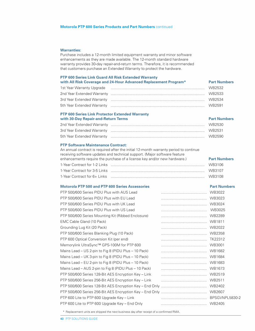
PTP SOLUTIONS GUIDE43
Warranties: Purchase includes a 12-month limited equipment warranty and minor software enhancements as they are made available. The 12-month standard hardware warranty provides 30-day repair-and-return terms. Therefore, it is recommended that customers purchase an Extended Warranty to protect the hardware.
pTp 600 Series Link Guard All Risk Extended Warranty with All Risk Coverage and �4-hour Advanced Replacement program* part Numbers
1st Year Warranty Upgrade ........................................................................................ WB2532
2nd Year Extended Warranty ........................................................................................ WB2533
3rd Year Extended Warranty ........................................................................................ WB2534
5th Year Extended Warranty ........................................................................................ WB2591
pTp 600 Series Link protector Extended Warranty with 30-Day Repair-and-Return Terms part Numbers
2nd Year Extended Warranty ........................................................................................ WB2530
3rd Year Extended Warranty ........................................................................................ WB2531
5th Year Extended Warranty ........................................................................................ WB2590
pTp Software Maintenance Contract: An annual contract is required after the initial 12-month warranty period to continue receiving software updates and technical support. (Major software feature enhancements require the purchase of a license key and/or new hardware.) part Numbers
1-Year Contract for 1-2 Links ........................................................................................ WB3106
1-Year Contract for 3-5 Links ........................................................................................ WB3107
1-Year Contract for 6+ Links ........................................................................................ WB3108
Motorola pTp 500 and pTp 600 Series Accessories part Numbers
PTP 500/600 Series PIDU Plus with AUS Lead ........................................... WB3022
PTP 500/600 Series PIDU Plus with EU Lead ........................................... WB3023
PTP 500/600 Series PIDU Plus with UK Lead ........................................... WB3024
PTP 500/600 Series PIDU Plus with US Lead ........................................... WB3025
PTP 500/600 Series Mounting Kit (Ribbed Enclosure) ........................................... WB2289
EMC Cable Gland (10 Pack) ........................................... WB1811
Grounding Lug Kit (20 Pack) ........................................... WB2022
PTP 500/600 Series Blanking Plug (10 Pack) ........................................... WB2358
PTP 600 Optical Conversion Kit (per end) ........................................... TK22312
Memorylink UltraSync™ GPS-100M for PTP 600 ........................................... WB3001
Mains Lead – US 2-pin to Fig 8 (PIDU Plus – 10 Pack) ........................................... WB1682
Mains Lead – UK 3-pin to Fig 8 (PIDU Plus – 10 Pack) ........................................... WB1684
Mains Lead – EU 2-pin to Fig 8 (PIDU Plus – 10 Pack) ........................................... WB1683
Mains Lead – AUS 2-pin to Fig 8 (PIDU Plus – 10 Pack) ........................................... WB1673
PTP 500/600 Series 128-Bit AES Encryption Key – Link ........................................... WB2519
PTP 500/600 Series 256-Bit AES Encryption Key – Link ........................................... WB2511
PTP 500/600 Series 128-Bit AES Encryption Key – End Only ........................................... WB2402
PTP 500/600 Series 256-Bit AES Encryption Key – End Only ........................................... WB2607
PTP 600 Lite to PTP 600 Upgrade Key – Link ........................................... BPSGVNPL5830-2
PTP 600 Lite to PTP 600 Upgrade Key – End Only ........................................... WB2405
Motorola pTp 600 Series products and part Numbers continued
* Replacement units are shipped the next business day after receipt of a confirmed RMA.
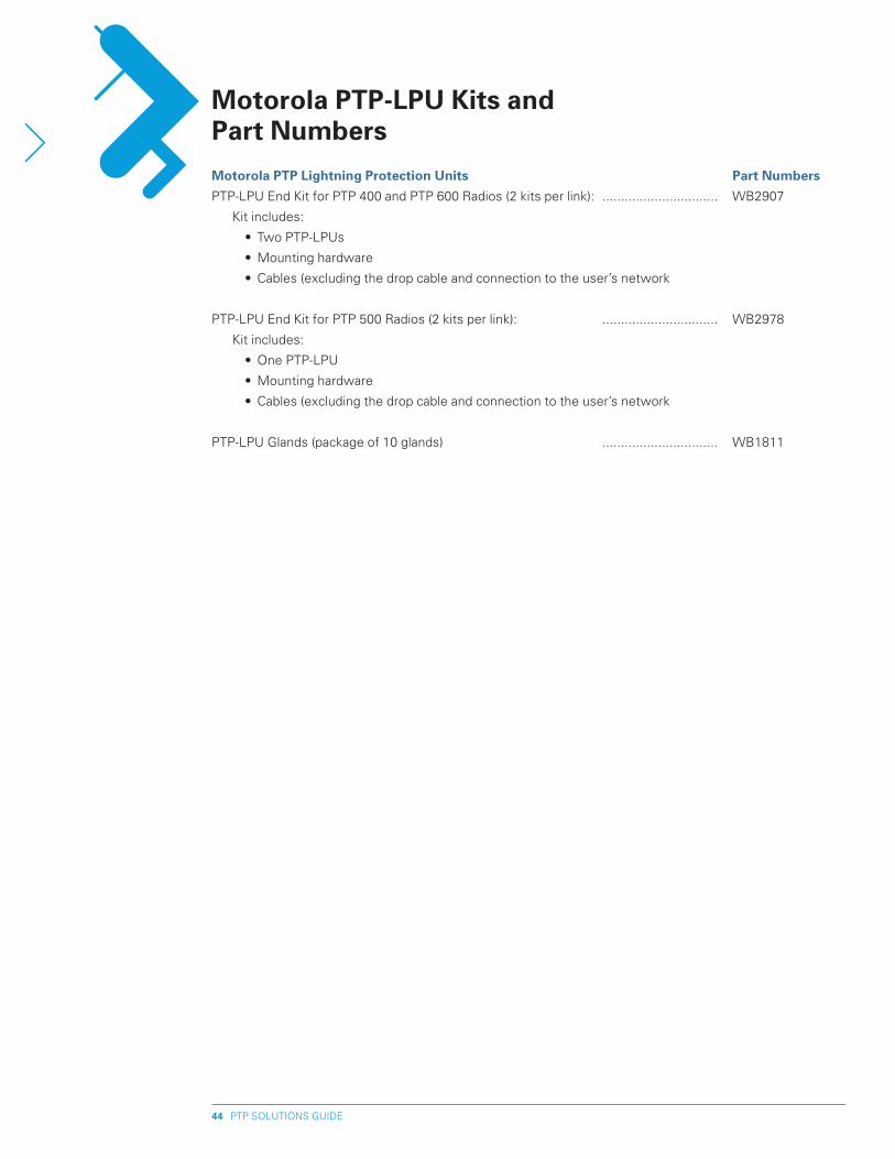
PTP SOLUTIONS GUIDE44
Motorola pTp Lightning protection Units part Numbers
PTP-LPU End Kit for PTP 400 and PTP 600 Radios (2 kits per link): ............................... WB2907
Kit includes:
• Two PTP-LPUs
• Mounting hardware
• Cables (excluding the drop cable and connection to the user’s network
PTP-LPU End Kit for PTP 500 Radios (2 kits per link): ............................... WB2978
Kit includes:
• One PTP-LPU
• Mounting hardware
• Cables (excluding the drop cable and connection to the user’s network
PTP-LPU Glands (package of 10 glands) ............................... WB1811
Motorola pTp-LpU Kits and part Numbers
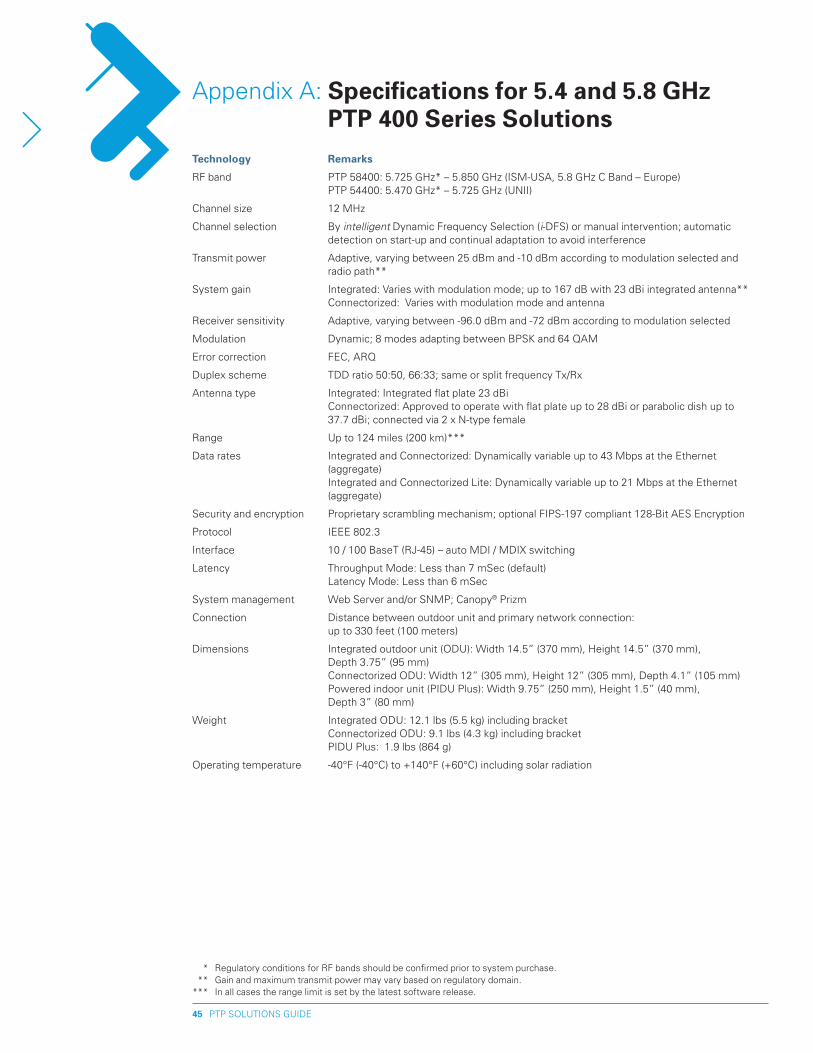
PTP SOLUTIONS GUIDE45
Technology Remarks
RF band PTP 58400: 5.725 GHz* – 5.850 GHz (ISM-USA, 5.8 GHz C Band – Europe) PTP 54400: 5.470 GHz* – 5.725 GHz (UNII)
Channel size 12 MHz
Channel selection By intelligent Dynamic Frequency Selection (i-DFS) or manual intervention; automatic detection on start-up and continual adaptation to avoid interference
Transmit power Adaptive, varying between 25 dBm and -10 dBm according to modulation selected and radio path**
System gain Integrated: Varies with modulation mode; up to 167 dB with 23 dBi integrated antenna** Connectorized: Varies with modulation mode and antenna
Receiver sensitivity Adaptive, varying between -96.0 dBm and -72 dBm according to modulation selected
Modulation Dynamic; 8 modes adapting between BPSK and 64 QAM
Error correction FEC, ARQ
Duplex scheme TDD ratio 50:50, 66:33; same or split frequency Tx/Rx
Antenna type Integrated: Integrated flat plate 23 dBi Connectorized: Approved to operate with flat plate up to 28 dBi or parabolic dish up to 37.7 dBi; connected via 2 x N-type female
Range Up to 124 miles (200 km)***
Data rates Integrated and Connectorized: Dynamically variable up to 43 Mbps at the Ethernet (aggregate) Integrated and Connectorized Lite: Dynamically variable up to 21 Mbps at the Ethernet (aggregate)
Security and encryption Proprietary scrambling mechanism; optional FIPS-197 compliant 128-Bit AES Encryption
Protocol IEEE 802.3
Interface 10 / 100 BaseT (RJ-45) – auto MDI / MDIX switching
Latency Throughput Mode: Less than 7 mSec (default) Latency Mode: Less than 6 mSec
System management Web Server and/or SNMP; Canopy® Prizm
Connection Distance between outdoor unit and primary network connection: up to 330 feet (100 meters)
Dimensions Integrated outdoor unit (ODU): Width 14.5” (370 mm), Height 14.5” (370 mm), Depth 3.75” (95 mm) Connectorized ODU: Width 12” (305 mm), Height 12” (305 mm), Depth 4.1” (105 mm) Powered indoor unit (PIDU Plus): Width 9.75” (250 mm), Height 1.5” (40 mm), Depth 3” (80 mm)
Weight Integrated ODU: 12.1 lbs (5.5 kg) including bracket Connectorized ODU: 9.1 lbs (4.3 kg) including bracket PIDU Plus: 1.9 lbs (864 g)
Operating temperature -40°F (-40°C) to +140°F (+60°C) including solar radiation
Appendix A: Specifications for 5.4 and 5.8 Ghz pTp 400 Series Solutions
* Regulatory conditions for RF bands should be confirmed prior to system purchase. ** Gain and maximum transmit power may vary based on regulatory domain. *** In all cases the range limit is set by the latest software release.
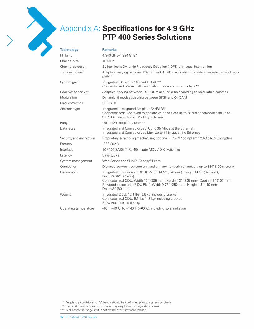
PTP SOLUTIONS GUIDE46
Technology Remarks
RF band 4.940 GHz–4.990 GHz*
Channel size 10 MHz
Channel selection By intelligent Dynamic Frequency Selection (i-DFS) or manual intervention
Transmit power Adaptive, varying between 23 dBm and -10 dBm according to modulation selected and radio path**
System gain Integrated: Between 163 and 134 dB** Connectorized: Varies with modulation mode and antenna type**
Receiver sensitivity Adaptive, varying between -96.0 dBm and -72 dBm according to modulation selected
Modulation Dynamic; 8 modes adapting between BPSK and 64 QAM
Error correction FEC, ARQ
Antenna type Integrated: Integrated flat plate 22 dBi / 8° Connectorized: Approved to operate with flat plate up to 28 dBi or parabolic dish up to
37.7 dBi; connected via 2 x N-type female
Range Up to 124 miles (200 km)***
Data rates Integrated and Connectorized: Up to 35 Mbps at the Ethernet Integrated and Connectorized Lite: Up to 17 Mbps at the Ethernet
Security and encryption Proprietary scrambling mechanism; optional FIPS-197 compliant 128-Bit AES Encryption
Protocol IEEE 802.3
Interface 10 / 100 BASE-T (RJ-45) – auto MDI/MDIX switching
Latency 5 ms typical
System management Web Server and SNMP; Canopy® Prizm
Connection Distance between outdoor unit and primary network connection: up to 330’ (100 meters)
Dimensions Integrated outdoor unit (ODU): Width 14.5” (370 mm), Height 14.5” (370 mm), Depth 3.75” (95 mm) Connectorized ODU: Width 12” (305 mm), Height 12” (305 mm), Depth 4.1” (105 mm) Powered indoor unit (PIDU Plus): Width 9.75” (250 mm), Height 1.5” (40 mm), Depth 3” (80 mm)
Weight Integrated ODU: 12.1 lbs (5.5 kg) including bracket Connectorized ODU: 9.1 lbs (4.3 kg) including bracket PIDU Plus: 1.9 lbs (864 g)
Operating temperature -40°F (-40°C) to +140°F (+60°C), including solar radiation
Appendix A: Specifications for 4.9 Ghz pTp 400 Series Solutions
* Regulatory conditions for RF bands should be confirmed prior to system purchase. ** Gain and maximum transmit power may vary based on regulatory domain. *** In all cases the range limit is set by the latest software release.
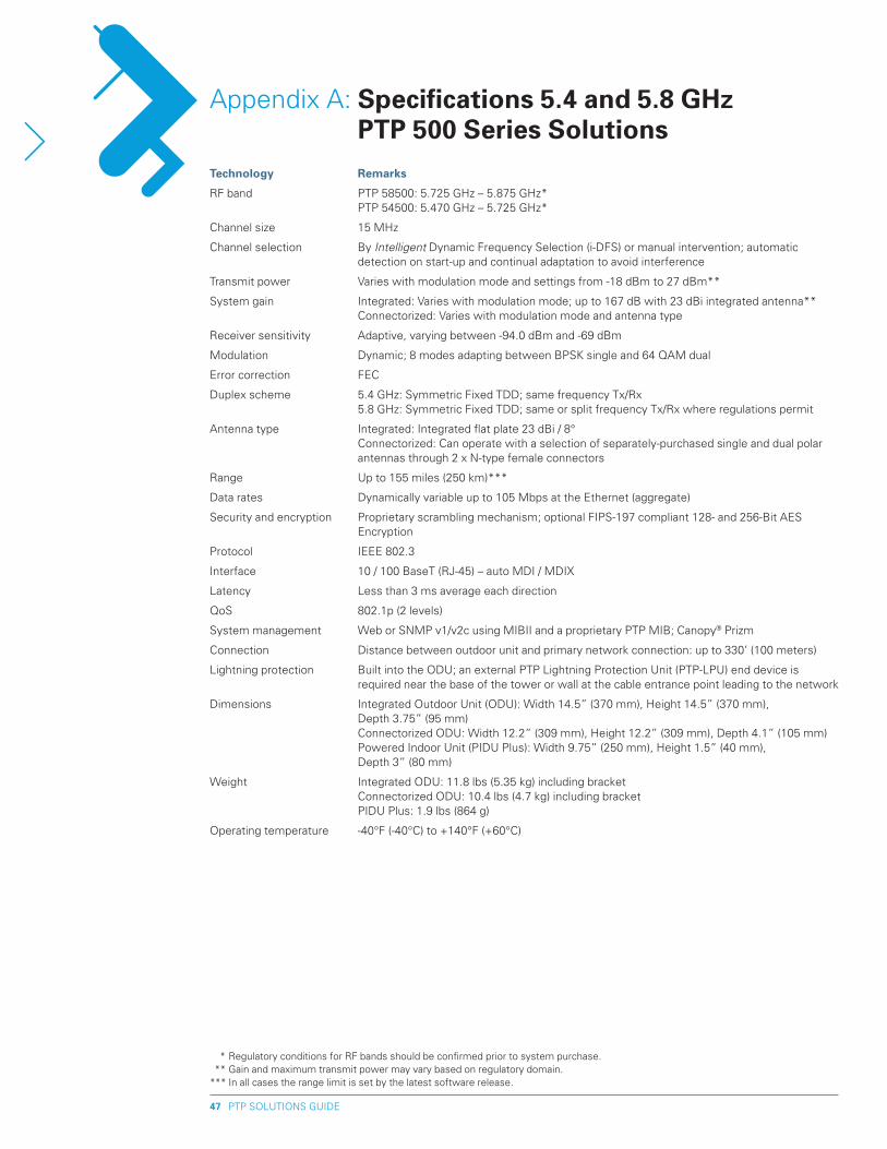
PTP SOLUTIONS GUIDE47
Technology Remarks
RF band PTP 58500: 5.725 GHz – 5.875 GHz* PTP 54500: 5.470 GHz – 5.725 GHz*
Channel size 15 MHz
Channel selection By Intelligent Dynamic Frequency Selection (i-DFS) or manual intervention; automatic detection on start-up and continual adaptation to avoid interference
Transmit power Varies with modulation mode and settings from -18 dBm to 27 dBm**
System gain Integrated: Varies with modulation mode; up to 167 dB with 23 dBi integrated antenna** Connectorized: Varies with modulation mode and antenna type
Receiver sensitivity Adaptive, varying between -94.0 dBm and -69 dBm
Modulation Dynamic; 8 modes adapting between BPSK single and 64 QAM dual
Error correction FEC
Duplex scheme 5.4 GHz: Symmetric Fixed TDD; same frequency Tx/Rx 5.8 GHz: Symmetric Fixed TDD; same or split frequency Tx/Rx where regulations permit
Antenna type Integrated: Integrated flat plate 23 dBi / 8° Connectorized: Can operate with a selection of separately-purchased single and dual polar
antennas through 2 x N-type female connectors
Range Up to 155 miles (250 km)***
Data rates Dynamically variable up to 105 Mbps at the Ethernet (aggregate)
Security and encryption Proprietary scrambling mechanism; optional FIPS-197 compliant 128- and 256-Bit AES Encryption
Protocol IEEE 802.3
Interface 10 / 100 BaseT (RJ-45) – auto MDI / MDIX
Latency Less than 3 ms average each direction
QoS 802.1p (2 levels)
System management Web or SNMP v1/v2c using MIBII and a proprietary PTP MIB; Canopy® Prizm
Connection Distance between outdoor unit and primary network connection: up to 330’ (100 meters)
Lightning protection Built into the ODU; an external PTP Lightning Protection Unit (PTP-LPU) end device is required near the base of the tower or wall at the cable entrance point leading to the network
Dimensions Integrated Outdoor Unit (ODU): Width 14.5” (370 mm), Height 14.5” (370 mm), Depth 3.75” (95 mm) Connectorized ODU: Width 12.2” (309 mm), Height 12.2” (309 mm), Depth 4.1” (105 mm) Powered Indoor Unit (PIDU Plus): Width 9.75” (250 mm), Height 1.5” (40 mm), Depth 3” (80 mm)
Weight Integrated ODU: 11.8 lbs (5.35 kg) including bracket Connectorized ODU: 10.4 lbs (4.7 kg) including bracket PIDU Plus: 1.9 lbs (864 g)
Operating temperature -40°F (-40°C) to +140°F (+60°C)
Appendix A: Specifications 5.4 and 5.8 Ghz pTp 500 Series Solutions
* Regulatory conditions for RF bands should be confirmed prior to system purchase. ** Gain and maximum transmit power may vary based on regulatory domain. *** In all cases the range limit is set by the latest software release.
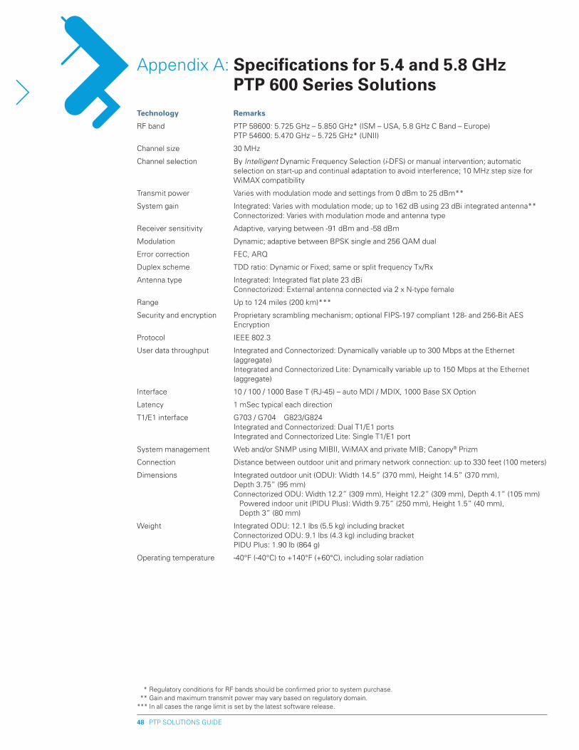
PTP SOLUTIONS GUIDE48
Technology Remarks
RF band PTP 58600: 5.725 GHz – 5.850 GHz* (ISM – USA, 5.8 GHz C Band – Europe) PTP 54600: 5.470 GHz – 5.725 GHz* (UNII)
Channel size 30 MHz
Channel selection By Intelligent Dynamic Frequency Selection (i-DFS) or manual intervention; automatic selection on start-up and continual adaptation to avoid interference; 10 MHz step size for WiMAX compatibility
Transmit power Varies with modulation mode and settings from 0 dBm to 25 dBm**
System gain Integrated: Varies with modulation mode; up to 162 dB using 23 dBi integrated antenna** Connectorized: Varies with modulation mode and antenna type
Receiver sensitivity Adaptive, varying between -91 dBm and -58 dBm
Modulation Dynamic; adaptive between BPSK single and 256 QAM dual
Error correction FEC, ARQ
Duplex scheme TDD ratio: Dynamic or Fixed; same or split frequency Tx/Rx
Antenna type Integrated: Integrated flat plate 23 dBi Connectorized: External antenna connected via 2 x N-type female
Range Up to 124 miles (200 km)***
Security and encryption Proprietary scrambling mechanism; optional FIPS-197 compliant 128- and 256-Bit AES Encryption
Protocol IEEE 802.3
User data throughput Integrated and Connectorized: Dynamically variable up to 300 Mbps at the Ethernet (aggregate) Integrated and Connectorized Lite: Dynamically variable up to 150 Mbps at the Ethernet (aggregate)
Interface 10 / 100 / 1000 Base T (RJ-45) – auto MDI / MDIX, 1000 Base SX Option
Latency 1 mSec typical each direction
T1/E1 interface G703 / G704 G823/G824 Integrated and Connectorized: Dual T1/E1 ports Integrated and Connectorized Lite: Single T1/E1 port
System management Web and/or SNMP using MIBII, WiMAX and private MIB; Canopy® Prizm
Connection Distance between outdoor unit and primary network connection: up to 330 feet (100 meters)
Dimensions Integrated outdoor unit (ODU): Width 14.5” (370 mm), Height 14.5” (370 mm), Depth 3.75” (95 mm) Connectorized ODU: Width 12.2” (309 mm), Height 12.2” (309 mm), Depth 4.1” (105 mm) Powered indoor unit (PIDU Plus): Width 9.75” (250 mm), Height 1.5” (40 mm),
Depth 3” (80 mm)
Weight Integrated ODU: 12.1 lbs (5.5 kg) including bracket Connectorized ODU: 9.1 lbs (4.3 kg) including bracket PIDU Plus: 1.90 lb (864 g)
Operating temperature -40°F (-40°C) to +140°F (+60°C), including solar radiation
Appendix A: Specifications for 5.4 and 5.8 Ghz pTp 600 Series Solutions
* Regulatory conditions for RF bands should be confirmed prior to system purchase. ** Gain and maximum transmit power may vary based on regulatory domain. *** In all cases the range limit is set by the latest software release.
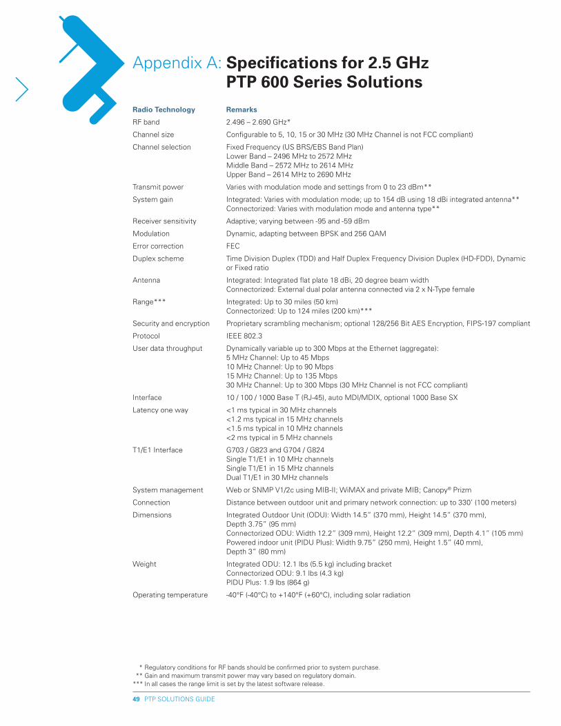
PTP SOLUTIONS GUIDE49
Radio Technology Remarks
RF band 2.496 – 2.690 GHz*
Channel size Configurable to 5, 10, 15 or 30 MHz (30 MHz Channel is not FCC compliant)
Channel selection Fixed Frequency (US BRS/EBS Band Plan) Lower Band – 2496 MHz to 2572 MHz Middle Band – 2572 MHz to 2614 MHz Upper Band – 2614 MHz to 2690 MHz
Transmit power Varies with modulation mode and settings from 0 to 23 dBm**
System gain Integrated: Varies with modulation mode; up to 154 dB using 18 dBi integrated antenna** Connectorized: Varies with modulation mode and antenna type**
Receiver sensitivity Adaptive; varying between -95 and -59 dBm
Modulation Dynamic, adapting between BPSK and 256 QAM
Error correction FEC
Duplex scheme Time Division Duplex (TDD) and Half Duplex Frequency Division Duplex (HD-FDD), Dynamic or Fixed ratio
Antenna Integrated: Integrated flat plate 18 dBi, 20 degree beam width Connectorized: External dual polar antenna connected via 2 x N-Type female
Range*** Integrated: Up to 30 miles (50 km) Connectorized: Up to 124 miles (200 km)***
Security and encryption Proprietary scrambling mechanism; optional 128/256 Bit AES Encryption, FIPS-197 compliant
Protocol IEEE 802.3
User data throughput Dynamically variable up to 300 Mbps at the Ethernet (aggregate): 5 MHz Channel: Up to 45 Mbps 10 MHz Channel: Up to 90 Mbps 15 MHz Channel: Up to 135 Mbps 30 MHz Channel: Up to 300 Mbps (30 MHz Channel is not FCC compliant)
Interface 10 / 100 / 1000 Base T (RJ-45), auto MDI/MDIX, optional 1000 Base SX
Latency one way <1 ms typical in 30 MHz channels <1.2 ms typical in 15 MHz channels <1.5 ms typical in 10 MHz channels <2 ms typical in 5 MHz channels
T1/E1 Interface G703 / G823 and G704 / G824 Single T1/E1 in 10 MHz channels Single T1/E1 in 15 MHz channels Dual T1/E1 in 30 MHz channels
System management Web or SNMP V1/2c using MIB-II; WiMAX and private MIB; Canopy® Prizm
Connection Distance between outdoor unit and primary network connection: up to 330’ (100 meters)
Dimensions Integrated Outdoor Unit (ODU): Width 14.5” (370 mm), Height 14.5” (370 mm), Depth 3.75” (95 mm) Connectorized ODU: Width 12.2” (309 mm), Height 12.2” (309 mm), Depth 4.1” (105 mm) Powered indoor unit (PIDU Plus): Width 9.75” (250 mm), Height 1.5” (40 mm), Depth 3” (80 mm)
Weight Integrated ODU: 12.1 lbs (5.5 kg) including bracket Connectorized ODU: 9.1 lbs (4.3 kg) PIDU Plus: 1.9 lbs (864 g)
Operating temperature -40°F (-40°C) to +140°F (+60°C), including solar radiation
Appendix A: Specifications for �.5 Ghz pTp 600 Series Solutions
* Regulatory conditions for RF bands should be confirmed prior to system purchase. ** Gain and maximum transmit power may vary based on regulatory domain. *** In all cases the range limit is set by the latest software release.
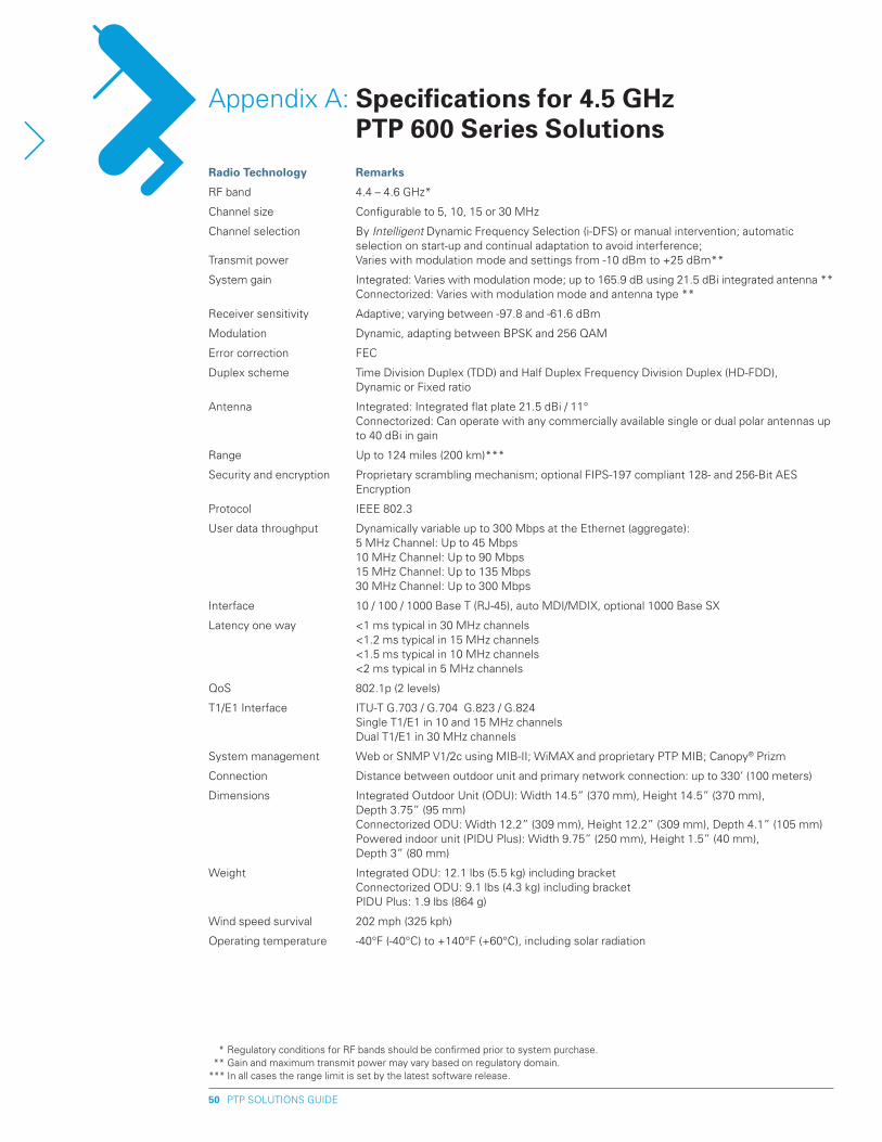
PTP SOLUTIONS GUIDE50
Radio Technology Remarks
RF band 4.4 – 4.6 GHz*
Channel size Configurable to 5, 10, 15 or 30 MHz
Channel selection By Intelligent Dynamic Frequency Selection (i-DFS) or manual intervention; automatic selection on start-up and continual adaptation to avoid interference;
Transmit power Varies with modulation mode and settings from -10 dBm to +25 dBm**
System gain Integrated: Varies with modulation mode; up to 165.9 dB using 21.5 dBi integrated antenna ** Connectorized: Varies with modulation mode and antenna type **
Receiver sensitivity Adaptive; varying between -97.8 and -61.6 dBm
Modulation Dynamic, adapting between BPSK and 256 QAM
Error correction FEC
Duplex scheme Time Division Duplex (TDD) and Half Duplex Frequency Division Duplex (HD-FDD), Dynamic or Fixed ratio
Antenna Integrated: Integrated flat plate 21.5 dBi / 11° Connectorized: Can operate with any commercially available single or dual polar antennas up to 40 dBi in gain
Range Up to 124 miles (200 km)***
Security and encryption Proprietary scrambling mechanism; optional FIPS-197 compliant 128- and 256-Bit AES Encryption
Protocol IEEE 802.3
User data throughput Dynamically variable up to 300 Mbps at the Ethernet (aggregate): 5 MHz Channel: Up to 45 Mbps 10 MHz Channel: Up to 90 Mbps 15 MHz Channel: Up to 135 Mbps 30 MHz Channel: Up to 300 Mbps
Interface 10 / 100 / 1000 Base T (RJ-45), auto MDI/MDIX, optional 1000 Base SX
Latency one way <1 ms typical in 30 MHz channels <1.2 ms typical in 15 MHz channels <1.5 ms typical in 10 MHz channels <2 ms typical in 5 MHz channels
QoS 802.1p (2 levels)
T1/E1 Interface ITU-T G.703 / G.704 G.823 / G.824 Single T1/E1 in 10 and 15 MHz channels Dual T1/E1 in 30 MHz channels
System management Web or SNMP V1/2c using MIB-II; WiMAX and proprietary PTP MIB; Canopy® Prizm
Connection Distance between outdoor unit and primary network connection: up to 330’ (100 meters)
Dimensions Integrated Outdoor Unit (ODU): Width 14.5” (370 mm), Height 14.5” (370 mm), Depth 3.75” (95 mm) Connectorized ODU: Width 12.2” (309 mm), Height 12.2” (309 mm), Depth 4.1” (105 mm) Powered indoor unit (PIDU Plus): Width 9.75” (250 mm), Height 1.5” (40 mm), Depth 3” (80 mm)
Weight Integrated ODU: 12.1 lbs (5.5 kg) including bracket Connectorized ODU: 9.1 lbs (4.3 kg) including bracket PIDU Plus: 1.9 lbs (864 g)
Wind speed survival 202 mph (325 kph)
Operating temperature -40°F (-40°C) to +140°F (+60°C), including solar radiation
Appendix A: Specifications for 4.5 Ghz pTp 600 Series Solutions
* Regulatory conditions for RF bands should be confirmed prior to system purchase. ** Gain and maximum transmit power may vary based on regulatory domain. *** In all cases the range limit is set by the latest software release.
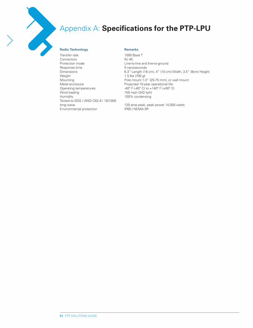
PTP SOLUTIONS GUIDE51
Radio Technology Remarks
Transfer rate 1000 Base TConnectors RJ 45Protection mode Line-to-line and line-to-groundResponse time 5 nanosecondsDimensions 6.3” Length (16 cm), 4” (10 cm) Width, 3.5” (9cm) HeightWeight 1.5 lbs (700 g)Mounting Pole mount 1-3” (25-75 mm), or wall mountMetal enclosure Projected 10-year operational lifeOperating temperatures -40° F (-40° C) to +140° F (+60° C)Wind loading 150 mph (242 kph)Humidity 100% condensing Tested to IEEE / ANSI C62.41 10/1000 long wave 120 amp peak, peak power 14,000 wattsEnvironmental protection IP65 / NEMA-3R
Appendix A: Specifications for the pTp-LpU
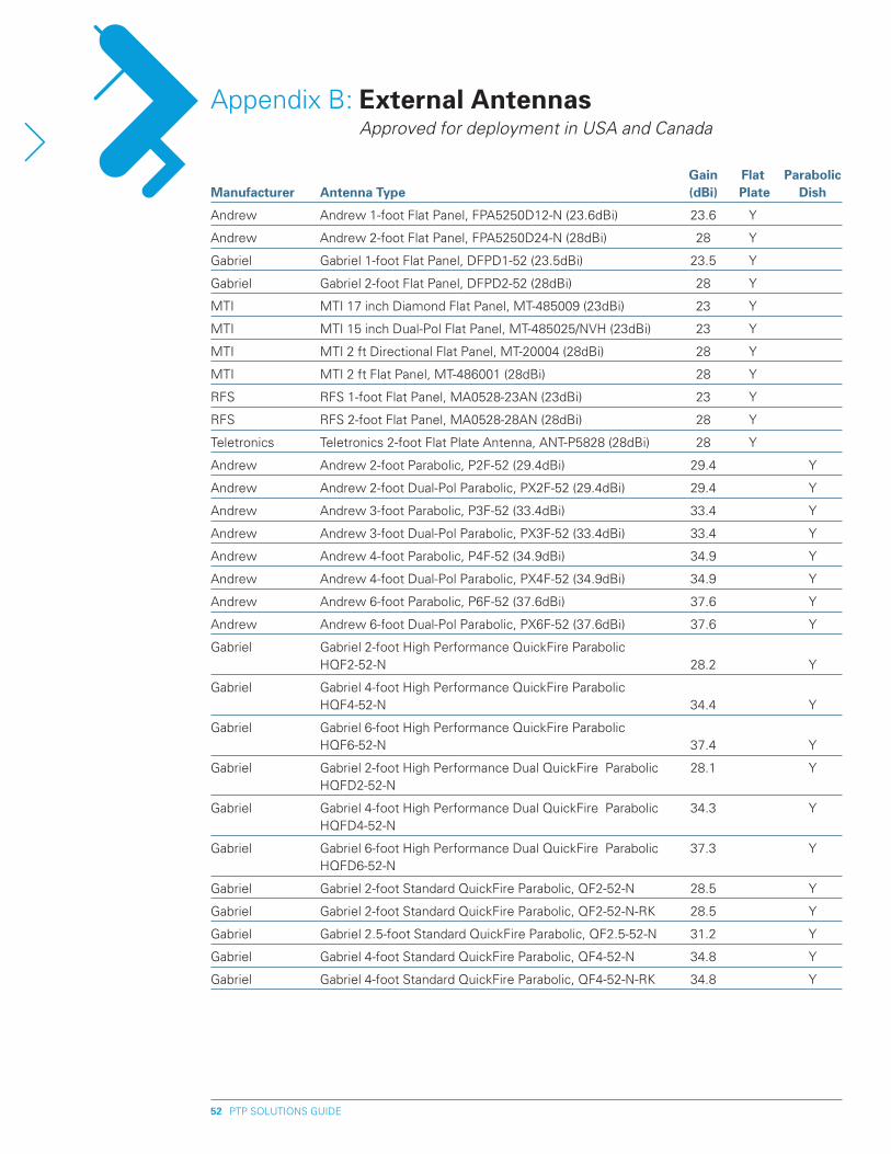
PTP SOLUTIONS GUIDE5�
Gain Flat parabolic Manufacturer Antenna Type (dBi) plate Dish
Andrew Andrew 1-foot Flat Panel, FPA5250D12-N (23.6dBi) 23.6 Y
Andrew Andrew 2-foot Flat Panel, FPA5250D24-N (28dBi) 28 Y
Gabriel Gabriel 1-foot Flat Panel, DFPD1-52 (23.5dBi) 23.5 Y
Gabriel Gabriel 2-foot Flat Panel, DFPD2-52 (28dBi) 28 Y
MTI MTI 17 inch Diamond Flat Panel, MT-485009 (23dBi) 23 Y
MTI MTI 15 inch Dual-Pol Flat Panel, MT-485025/NVH (23dBi) 23 Y
MTI MTI 2 ft Directional Flat Panel, MT-20004 (28dBi) 28 Y
MTI MTI 2 ft Flat Panel, MT-486001 (28dBi) 28 Y
RFS RFS 1-foot Flat Panel, MA0528-23AN (23dBi) 23 Y
RFS RFS 2-foot Flat Panel, MA0528-28AN (28dBi) 28 Y
Teletronics Teletronics 2-foot Flat Plate Antenna, ANT-P5828 (28dBi) 28 Y
Andrew Andrew 2-foot Parabolic, P2F-52 (29.4dBi) 29.4 Y
Andrew Andrew 2-foot Dual-Pol Parabolic, PX2F-52 (29.4dBi) 29.4 Y
Andrew Andrew 3-foot Parabolic, P3F-52 (33.4dBi) 33.4 Y
Andrew Andrew 3-foot Dual-Pol Parabolic, PX3F-52 (33.4dBi) 33.4 Y
Andrew Andrew 4-foot Parabolic, P4F-52 (34.9dBi) 34.9 Y
Andrew Andrew 4-foot Dual-Pol Parabolic, PX4F-52 (34.9dBi) 34.9 Y
Andrew Andrew 6-foot Parabolic, P6F-52 (37.6dBi) 37.6 Y
Andrew Andrew 6-foot Dual-Pol Parabolic, PX6F-52 (37.6dBi) 37.6 Y
Gabriel Gabriel 2-foot High Performance QuickFire Parabolic HQF2-52-N 28.2 Y
Gabriel Gabriel 4-foot High Performance QuickFire Parabolic HQF4-52-N 34.4 Y
Gabriel Gabriel 6-foot High Performance QuickFire Parabolic HQF6-52-N 37.4 Y
Gabriel Gabriel 2-foot High Performance Dual QuickFire Parabolic 28.1 Y HQFD2-52-N
Gabriel Gabriel 4-foot High Performance Dual QuickFire Parabolic 34.3 Y HQFD4-52-N
Gabriel Gabriel 6-foot High Performance Dual QuickFire Parabolic 37.3 Y HQFD6-52-N
Gabriel Gabriel 2-foot Standard QuickFire Parabolic, QF2-52-N 28.5 Y
Gabriel Gabriel 2-foot Standard QuickFire Parabolic, QF2-52-N-RK 28.5 Y
Gabriel Gabriel 2.5-foot Standard QuickFire Parabolic, QF2.5-52-N 31.2 Y
Gabriel Gabriel 4-foot Standard QuickFire Parabolic, QF4-52-N 34.8 Y
Gabriel Gabriel 4-foot Standard QuickFire Parabolic, QF4-52-N-RK 34.8 Y
Appendix B: External Antennas Approved for deployment in USA and Canada
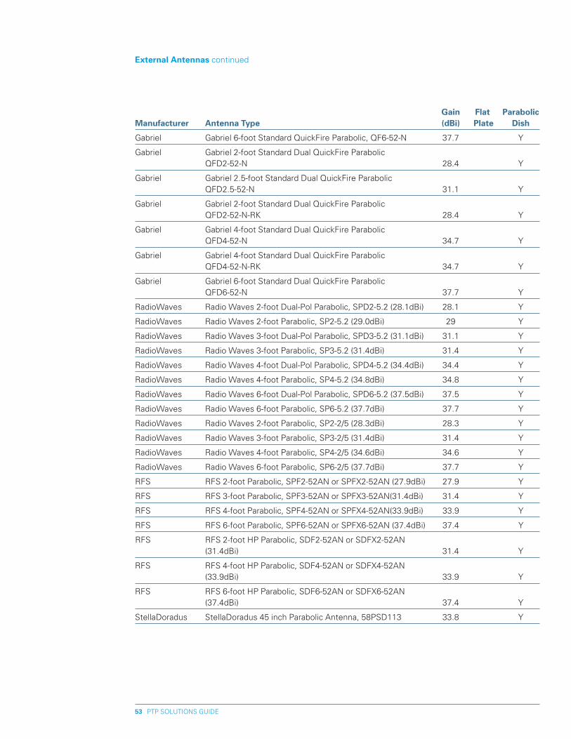
PTP SOLUTIONS GUIDE53
Gain Flat parabolic Manufacturer Antenna Type (dBi) plate Dish
Gabriel Gabriel 6-foot Standard QuickFire Parabolic, QF6-52-N 37.7 Y
Gabriel Gabriel 2-foot Standard Dual QuickFire Parabolic QFD2-52-N 28.4 Y
Gabriel Gabriel 2.5-foot Standard Dual QuickFire Parabolic QFD2.5-52-N 31.1 Y
Gabriel Gabriel 2-foot Standard Dual QuickFire Parabolic QFD2-52-N-RK 28.4 Y
Gabriel Gabriel 4-foot Standard Dual QuickFire Parabolic QFD4-52-N 34.7 Y
Gabriel Gabriel 4-foot Standard Dual QuickFire Parabolic QFD4-52-N-RK 34.7 Y
Gabriel Gabriel 6-foot Standard Dual QuickFire Parabolic QFD6-52-N 37.7 Y
RadioWaves Radio Waves 2-foot Dual-Pol Parabolic, SPD2-5.2 (28.1dBi) 28.1 Y
RadioWaves Radio Waves 2-foot Parabolic, SP2-5.2 (29.0dBi) 29 Y
RadioWaves Radio Waves 3-foot Dual-Pol Parabolic, SPD3-5.2 (31.1dBi) 31.1 Y
RadioWaves Radio Waves 3-foot Parabolic, SP3-5.2 (31.4dBi) 31.4 Y
RadioWaves Radio Waves 4-foot Dual-Pol Parabolic, SPD4-5.2 (34.4dBi) 34.4 Y
RadioWaves Radio Waves 4-foot Parabolic, SP4-5.2 (34.8dBi) 34.8 Y
RadioWaves Radio Waves 6-foot Dual-Pol Parabolic, SPD6-5.2 (37.5dBi) 37.5 Y
RadioWaves Radio Waves 6-foot Parabolic, SP6-5.2 (37.7dBi) 37.7 Y
RadioWaves Radio Waves 2-foot Parabolic, SP2-2/5 (28.3dBi) 28.3 Y
RadioWaves Radio Waves 3-foot Parabolic, SP3-2/5 (31.4dBi) 31.4 Y
RadioWaves Radio Waves 4-foot Parabolic, SP4-2/5 (34.6dBi) 34.6 Y
RadioWaves Radio Waves 6-foot Parabolic, SP6-2/5 (37.7dBi) 37.7 Y
RFS RFS 2-foot Parabolic, SPF2-52AN or SPFX2-52AN (27.9dBi) 27.9 Y
RFS RFS 3-foot Parabolic, SPF3-52AN or SPFX3-52AN(31.4dBi) 31.4 Y
RFS RFS 4-foot Parabolic, SPF4-52AN or SPFX4-52AN(33.9dBi) 33.9 Y
RFS RFS 6-foot Parabolic, SPF6-52AN or SPFX6-52AN (37.4dBi) 37.4 Y
RFS RFS 2-foot HP Parabolic, SDF2-52AN or SDFX2-52AN (31.4dBi) 31.4 Y
RFS RFS 4-foot HP Parabolic, SDF4-52AN or SDFX4-52AN (33.9dBi) 33.9 Y
RFS RFS 6-foot HP Parabolic, SDF6-52AN or SDFX6-52AN (37.4dBi) 37.4 Y
StellaDoradus StellaDoradus 45 inch Parabolic Antenna, 58PSD113 33.8 Y
External Antennas continued
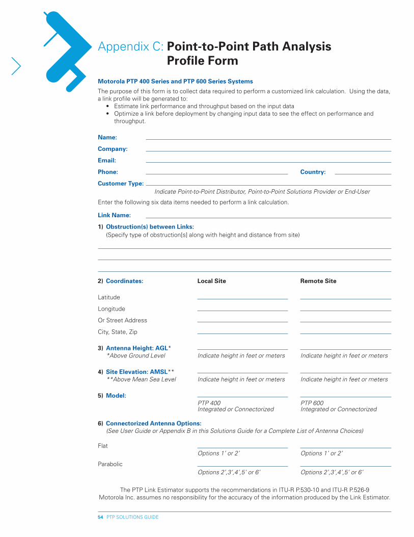
PTP SOLUTIONS GUIDE54
Motorola pTp 400 Series and pTp 600 Series Systems
The purpose of this form is to collect data required to perform a customized link calculation. Using the data, a link profile will be generated to: • Estimate link performance and throughput based on the input data • Optimize a link before deployment by changing input data to see the effect on performance and
throughput.
Name:
Company:
Email:
phone: Country:
Customer Type: Indicate Point-to-Point Distributor, Point-to-Point Solutions Provider or End-User
Enter the following six data items needed to perform a link calculation.
Link Name:
1) Obstruction(s) between Links: (Specify type of obstruction[s] along with height and distance from site)
�) Coordinates: Local Site Remote Site
Latitude
Longitude
Or Street Address
City, State, Zip 3) Antenna height: AGL* *Above Ground Level Indicate height in feet or meters Indicate height in feet or meters
4) Site Elevation: AMSL** **Above Mean Sea Level Indicate height in feet or meters Indicate height in feet or meters
5) Model: PTP 400 PTP 600 Integrated or Connectorized Integrated or Connectorized
6) Connectorized Antenna Options: (See User Guide or Appendix B in this Solutions Guide for a Complete List of Antenna Choices)
Flat Options 1’ or 2’ Options 1’ or 2’
Parabolic Options 2’,3’,4’,5’ or 6’ Options 2’,3’,4’,5’ or 6’
The PTP Link Estimator supports the recommendations in ITU-R P.530-10 and ITU-R P.526-9
Motorola Inc. assumes no responsibility for the accuracy of the information produced by the Link Estimator.
Appendix C: point-to-point path Analysis profile Form

PTP SOLUTIONS GUIDE55
Motorola, Inc., 1303 E. Algonquin Road, Schaumburg, Illinois 60196 U.S.A. • www.motorola.com/ptp
The contents of this Solutions Guide are subject to change without notice.
MOTOROLA and the Stylized M Logo are registered in the U.S. Patent and Trademark Office. All other product or service names are the property of their respective owners. © Motorola, Inc. 2008. All rights reserved.
GPS WB PTP SOLUTIONS GD 040908
MOTOROLA WI4 FIxED pOINT-TO-pOINT SOLUTIONS GUIDE