Embed Size (px)
Citation preview

Reference Guide PTP 820 Series MIB
System Release 10.9

phn-3974
Accuracy While reasonable efforts have been made to assure the accuracy of this document, Cambium Networks assumes no liability resulting from any inaccuracies or omissions in this document, or from use of the information obtained herein. Cambium reserves the right to make changes to any products described herein to improve reliability, function, or design, and reserves the right to revise this document and to make changes from time to time in content hereof with no obligation to notify any person of revisions or changes. Cambium does not assume any liability arising out of the application or use of any product, software, or circuit described herein; neither does it convey license under its patent rights or the rights of others. It is possible that this publication may contain references to, or information about Cambium products (machines and programs), programming, or services that are not announced in your country. Such references or information must not be construed to mean that Cambium intends to announce such Cambium products, programming, or services in your country. Copyrights This document, Cambium products, and 3rd Party software products described in this document may include or describe copyrighted Cambium and other 3rd Party supplied computer programs stored in semiconductor memories or other media. Laws in the United States and other countries preserve for Cambium, its licensors, and other 3rd Party supplied software certain exclusive rights for copyrighted material, including the exclusive right to copy, reproduce in any form, distribute and make derivative works of the copyrighted material. Accordingly, any copyrighted material of Cambium, its licensors, or the 3rd Party software supplied material contained in the Cambium products described in this document may not be copied, reproduced, reverse engineered, distributed, merged or modified in any manner without the express written permission of Cambium. Furthermore, the purchase of Cambium products shall not be deemed to grant either directly or by implication, estoppel, or otherwise, any license under the copyrights, patents or patent applications of Cambium or other 3rd Party supplied software, except for the normal non-exclusive, royalty free license to use that arises by operation of law in the sale of a product. Restrictions Software and documentation are copyrighted materials. Making unauthorized copies is prohibited by law. No part of the software or documentation may be reproduced, transmitted, transcribed, stored in a retrieval system, or translated into any language or computer language, in any form or by any means, without prior written permission of Cambium. License Agreements The software described in this document is the property of Cambium and its licensors. It is furnished by express license agreement only and may be used only in accordance with the terms of such an agreement. High Risk Materials Cambium and its supplier(s) specifically disclaim any express or implied warranty of fitness for any high risk activities or uses of its products including, but not limited to, the operation of nuclear facilities, aircraft navigation or aircraft communication systems, air traffic control, life support, or weapons systems (“High Risk Use”). Any High Risk is unauthorized, is made at your own risk and you shall be responsible for any and all losses, damage or claims arising out of any High Risk Use.
© 2019 Cambium Networks Limited. All Rights Reserved.

phn-3974 008v000 Page i
Contents
About This User Guide ........................................................................................................................................... 1 Contacting Cambium Networks ...................................................................................................................... 1 Purpose ........................................................................................................................................................... 2 Cross references .............................................................................................................................................. 2 Feedback ......................................................................................................................................................... 2
Problems and warranty .......................................................................................................................................... 3 Reporting problems ......................................................................................................................................... 3 Repair and service ........................................................................................................................................... 3 Hardware warranty ......................................................................................................................................... 3
Security advice ........................................................................................................................................................ 4 Warnings, cautions, and notes ............................................................................................................................... 5
Warnings ......................................................................................................................................................... 5 Cautions ........................................................................................................................................................... 5 Notes ............................................................................................................................................................... 5
Caring for the environment .................................................................................................................................... 6 In EU countries ................................................................................................................................................ 6 In non-EU countries ......................................................................................................................................... 6
Chapter 1: Introduction .................................................................................................................................. 1-1 Chapter 2: Private MIB Reference................................................................................................................... 2-1
MIB File Names and Versions ............................................................................................................................. 2-2 Chapter 3: Standard MIB support ................................................................................................................... 3-1
RFC-1213 (MIB II) ................................................................................................................................................ 3-2 System parameters ..................................................................................................................................... 3-2 Interfaces ..................................................................................................................................................... 3-3 ifTable .......................................................................................................................................................... 3-3 IfXTable ........................................................................................................................................................ 3-4 RMON – etherStatsTable ............................................................................................................................. 3-5 RMON – etherStatsHighCapacityTable ........................................................................................................ 3-5 IfIndex .......................................................................................................................................................... 3-6 NG Interface Format .................................................................................................................................... 3-6 NG Service Format ....................................................................................................................................... 3-7 Other parameters and tables ...................................................................................................................... 3-8
Multiple Spanning Tree Protocol (MSTP) ............................................................................................................ 3-9 Traps ID ............................................................................................................................................................. 3-10
Trap Var Bind ............................................................................................................................................. 3-10 Chapter 4: Common Tasks .............................................................................................................................. 4-1
Software Management ....................................................................................................................................... 4-2

Contents
phn-3974 008v000 Page ii
Downloading a software version ................................................................................................................. 4-2 Upgrading the RFU software version .......................................................................................................... 4-5
Configuration file management .......................................................................................................................... 4-7 System configuration FTP settings .............................................................................................................. 4-7 Creating and uploading backup configuration archives .............................................................................. 4-8
Enabling and configuring traps .......................................................................................................................... 4-10 Enabling trap administration ..................................................................................................................... 4-10 Managing a trap ........................................................................................................................................ 4-10
Viewing current alarms ..................................................................................................................................... 4-12 Alarm date and time .................................................................................................................................. 4-12 Alarm severity ........................................................................................................................................... 4-12 Affected module ........................................................................................................................................ 4-12 Alarm description ...................................................................................................................................... 4-13 Probable cause .......................................................................................................................................... 4-13 Corrective actions ...................................................................................................................................... 4-13
Performance monitoring and counters ............................................................................................................ 4-14 Clearing all performance counter data ..................................................................................................... 4-14
Managing radio configuration .......................................................................................................................... 4-15 Setting the radio threshold ....................................................................................................................... 4-15 Setting the traffic PM thresholds .............................................................................................................. 4-15
Chapter 5: MIB Revision History ................................................................................................................... 5-17 Chapter 6: MIB error table (Reserved for future use) ................................................................................... 6-18 Chapter 7: Alarms ........................................................................................................................................... 7-1
List of Tables Table 1 MIB File Names and Versions ....................................................................................................................... 2-2 Table 2 System parameters ...................................................................................................................................... 3-2 Table 3 System Object IDs (sysObjectID) .................................................................................................................. 3-2 Table 4 Supported IfTables ....................................................................................................................................... 3-3 Table 5 Standard IfXtable support ............................................................................................................................ 3-4 Table 6 Standard IfXtable support ............................................................................................................................ 3-5 Table 7 Standard IfXtable support ............................................................................................................................ 3-5 Table 8 IfIndex Structure .......................................................................................................................................... 3-6 Table 9 IfIndex “Format” Field Optional Values ....................................................................................................... 3-6 Table 10 NG Interface Format IfIndex Structure ...................................................................................................... 3-6 Table 11 IfIndex “Interface Functional Type” Field Optional Values ........................................................................ 3-7 Table 12 IfIndex “Slot” Field Optional Values ........................................................................................................... 3-7 Table 13 IfIndex “Port/Group” Field Optional Values ............................................................................................... 3-7 Table 14 NG Service Format IfIndex Structure ......................................................................................................... 3-7 Table 15 Service Type ............................................................................................................................................... 3-8 Table 16 Other Supported Networking Parameters ................................................................................................. 3-8 Table 17 Network MIB ............................................................................................................................................ 3-10

Contents
phn-3974 008v000 Page iii
Table 18 Trap Var-Bind Parameters ........................................................................................................................ 3-10 Table 19 MIB Objects for Configuring FTP Parameters ............................................................................................ 4-2 Table 20 Managing software versions MIB object .................................................................................................... 4-3 Table 21 MIB objects for Checking IDU Software Status .......................................................................................... 4-4 Table 22 Upgrading RFU software version MIB object ............................................................................................. 4-6 Table 23 MIB objects for checking RFU software status ........................................................................................... 4-6 Table 24 MIB objects for configuring FTP settings ................................................................................................... 4-7 Table 25 Creating Configuration Archive MIB Object ............................................................................................... 4-8 Table 26 Uploading Archived Configuration MIB Object .......................................................................................... 4-8 Table 27 Backup and Upload Status MIB Object ...................................................................................................... 4-9 Table 28 Enabling Trap Administration................................................................................................................... 4-10 Table 29 Managing a trap - Index: genEquipTrapCfgMgrId .................................................................................... 4-10 Table 30 Alarm date and time MIB object .............................................................................................................. 4-12 Table 31 Alarm severity MIB object ........................................................................................................................ 4-12 Table 32 Affected Module MIB Object ................................................................................................................... 4-12 Table 33 Alarm Description MIB Object ................................................................................................................. 4-13 Table 34 Probable Alarm Cause MIB Object ........................................................................................................... 4-13 Table 35 Corrective Actions MIB Object ................................................................................................................. 4-13 Table 36 Setting RSL Threshold ............................................................................................................................... 4-15 Table 37 Setting Traffic PMThresholds ................................................................................................................... 4-15 Table 38 PTP 820 Alarms .......................................................................................................................................... 7-1

phn-3974 008v000 Page 1
About This User Guide
This guide describes the PTP 820 Series products MIB tables and alarms.
This guide contains the following chapters:
• Chapter 1: Introduction
• Chapter 2: Private MIB Reference
• Chapter 3: Standard MIB support
• Chapter 4: Common Tasks
• MIB Revision History
• Chapter 6: MIB error table (Reserved for future use)
• Chapter 7: Alarms
Contacting Cambium Networks
Support website: https://support.cambiumnetworks.com
Main website: http://www.cambiumnetworks.com
Sales enquiries: [email protected]
Support enquiries: https://support.cambiumnetworks.com
Repair inquiries https://support.cambiumnetworks.com
Telephone number list: http://www.cambiumnetworks.com/support/contact-support
Address: Cambium Networks Limited, Linhay Business Park, Eastern Road, Ashburton, Devon, UK, TQ13 7UP

About This User Guide Problems and warranty
phn-3974 008v000 Page 2
Purpose Cambium Networks Point-To-Point (PTP) documents are intended to instruct and assist personnel in the operation, installation and maintenance of the Cambium PTP equipment and ancillary devices. It is recommended that all personnel engaged in such activities be properly trained.
Cambium disclaims all liability whatsoever, implied or express, for any risk of damage, loss or reduction in system performance arising directly or indirectly out of the failure of the customer, or anyone acting on the customer's behalf, to abide by the instructions, system parameters, or recommendations made in this document.
Cross references References to external publications are shown in italics. Other cross references, emphasized in blue text in electronic versions, are active links to the references.
This document is divided into numbered chapters that are divided into sections. Sections are not numbered, but are individually named at the top of each page, and are listed in the table of contents.
Feedback We appreciate feedback from the users of our documents. This includes feedback on the structure, content, accuracy, or completeness of our documents. Send feedback to [email protected].

About This User Guide Problems and warranty
phn-3974 008v000 Page 3
Problems and warranty
Reporting problems If any problems are encountered when installing or operating this equipment, follow this procedure to investigate and report:
1 Search this document and the software release notes of supported releases.
2 Visit the support website.
3 Ask for assistance from the Cambium product supplier.
4 Gather information from affected units, such as any available diagnostic downloads.
5 Escalate the problem by emailing or telephoning support.
Repair and service If unit failure is suspected, obtain details of the Return Material Authorization (RMA) process from the support website.
Hardware warranty Cambium’s standard hardware warranty is for one (1) year from date of shipment from Cambium Networks or a Cambium distributor. Cambium Networks warrants that hardware will conform to the relevant published specifications and will be free from material defects in material and workmanship under normal use and service. Cambium shall within this time, at its own option, either repair or replace the defective product within thirty (30) days of receipt of the defective product. Repaired or replaced product will be subject to the original warranty period but not less than thirty (30) days.
To register PTP products or activate warranties, visit the support website. For warranty assistance, contact the reseller or distributor.
Caution
Using non-Cambium parts for repair could damage the equipment or void warranty. Contact Cambium for service and repair instructions.
Portions of Cambium equipment may be damaged from exposure to electrostatic discharge. Use precautions to prevent damage.
About This User Guide Security advice
phn-3974 008v000 Page 4
Security advice
Cambium Networks systems and equipment provide security parameters that can be configured by the operator based on their particular operating environment. Cambium recommends setting and using these parameters following industry recognized security practices. Security aspects to be considered are protecting the confidentiality, integrity, and availability of information and assets. Assets include the ability to communicate, information about the nature of the communications, and information about the parties involved.
In certain instances Cambium makes specific recommendations regarding security practices, however the implementation of these recommendations and final responsibility for the security of the system lies with the operator of the system.

About This User Guide Warnings, cautions, and notes
phn-3974 008v000 Page 5
Warnings, cautions, and notes
The following describes how warnings and cautions are used in this document and in all documents of the Cambium Networks document set.
Warnings Warnings precede instructions that contain potentially hazardous situations. Warnings are used to alert the reader to possible hazards that could cause loss of life or physical injury. A warning has the following format:
Warning
Warning text and consequence for not following the instructions in the warning.
Cautions Cautions precede instructions and are used when there is a possibility of damage to systems, software, or individual items of equipment within a system. However, this damage presents no danger to personnel. A caution has the following format:
Caution
Caution text and consequence for not following the instructions in the caution.
Notes A note means that there is a possibility of an undesirable situation or provides additional information to help the reader understand a topic or concept. A note has the following format:
Note
Note text.

About This User Guide Caring for the environment
phn-3974 008v000 Page 6
Caring for the environment
The following information describes national or regional requirements for the disposal of Cambium Networks supplied equipment and for the approved disposal of surplus packaging.
In EU countries The following information is provided to enable regulatory compliance with the European Union (EU) directives identified and any amendments made to these directives when using Cambium equipment in EU countries.
Disposal of Cambium equipment European Union (EU) Directive 2002/96/EC Waste Electrical and Electronic Equipment (WEEE)
Do not dispose of Cambium equipment in landfill sites. For disposal instructions, refer to http://www.cambiumnetworks.com/support
Disposal of surplus packaging Do not dispose of surplus packaging in landfill sites. In the EU, it is the individual recipient’s responsibility to ensure that packaging materials are collected and recycled according to the requirements of EU environmental law.
In non-EU countries In non-EU countries, dispose of Cambium equipment and all surplus packaging in accordance with national and regional regulations.
phn-3974 008v000 Page 1-1
Chapter 1: Introduction
This document applies to the following Cambium Networks PTP 820 series products:
• PTP 820C
• PTP 820C-HP
• PTP 820S
• PTP 820G
• PTP 820F
• PTP 820E

phn-3974 008v000 Page 2-1
Chapter 2: Private MIB Reference
This chapter describes MIB Files and Private MIB Entities of PTP 820:
• MIB File Names and Versions

Chapter 2: Private MIB Reference MIB File Names and Versions
phn-3974 008v000 Page 2-2
MIB File Names and Versions
The MIB files and file versions supported by the PTP 820 products in System Release 10.0:
Table 1 MIB File Names and Versions
MIB File Name MIB File Version
Description
MWRM-NETWORK-MIB 1.10.9.3 Networking related OIDs, including Ethernet switch configuration, forwarding, quality of service (QoS), policing, control protocols, and management.
MWRM-PM-MIB 1.10.9.2 Performance Monitoring OIDs for Ethernet and radio.
MWRM-RADIO-MIB 1.10.9.2 Radio related OIDs, including RFU and radio management, MRMC, radio group management (HSB, ABC), header de-duplication, and frame cut-through.
MWRM-TRAPS-MIB 1.10.9.1 Describes the IP-20 device-specific traps.
MWRM-UNIT-MIB 1.10.9.1 General platform-related OIDs, including alarm and event services, NTP, license, software version management, configuration management, and security and access control.
MWRM-DEFS.MIB OID for microwave-radio (formerly in MMRM-RADIO-MIB).
Note
Prior to release 10.7, the material in the MWRM-TRAPS-MIB file was contained in the MWRM-NETWORK-MIB file.
You can display a list of entities in the private MIB from the Web EMS of the PTP 820 unit:
1. From the Web EMS main menu, select Utilities -> MIB Reference Guide. The MIB Reference Table opens.

Chapter 2: Private MIB Reference MIB File Names and Versions
phn-3974 008v000 Page 2-3
Figure 1 MIB Reference Table in Web EMS
The MIB Reference Table is customized to the type of PTP 820 product you are using. There are three separate versions of the MIB Reference Table:
• PTP 820G
• PTP 820C/S
• PTP 820C-HP
• PTP 820F
• PTP 820E
• To search for a text string, enter the string in the Search field and press
• <Enter>. Items that contain the string are displayed in yellow. Searches are not case-sensitive.
• To save the MIB Reference Table as a .csv file, click Save to File
Note
Even through the MIB Reference Table is customized to these three product groups, some of the entities listed in the Table may not be relevant to the particular unit you are using. This may occur because of activation key restrictions, minor differences between product types, or simply because a certain feature is not used in a particular configuration.

phn-3974 008v000 Page 3-1
Chapter 3: Standard MIB support
This chapter details the public MIB standards supported by the PTP 820 MIB.
This chapter includes:
• RFC-1213 (MIB II)
• Multiple Spanning Tree Protocol (MSTP)
• Traps

Chapter 3: Standard MIB support RFC-1213 (MIB II)
phn-3974 008v000 Page 3-2
RFC-1213 (MIB II)
This section details the implementation of each area of the RFC-1213 standard within the context of the PTP 820 MIB.
System parameters The table below details the legal values for each system parameter within RFC-1213 from implementation within the PTP 820 MIB.
Table 2 System parameters
Parameter Access Description
sysDescr Read only A description of the network element.
sysUpTime Read only The time (in hundredths of a second) since the network management portion of the system was last re-initialized
sysContact Read write The name of the contact person for this network element
sysName Read write An administratively assigned name for the network element. By convention, this is the node's fully qualified domain name
sysLocation Read write The physical location of the network element of this node
The table below details the System Object IDs (sysObjectID) within the PTP 820 MIB. The sysObjectID is a unique identifier for the product type.
Table 3 System Object IDs (sysObjectID)
Product System Object ID SysDescr
PTP 820 Products 1.3.6.1.4.1.2281.1.20 High capacity packet radio unit
PTP 820G Indoor Units 1.3.6.1.4.1.2281.1.20.1.3 High capacity packet radio 1U indoor unit
PTP 820G 1.3.6.1.4.1.2281.1.20.1.3.1 High capacity dual carrier packet radio 1U indoor unit
All Outdoor Units 1.3.6.1.4.1.2281.1.20.2.2 High capacity packet radio outdoor unit
PTP 820C 1.3.6.1.4.1.2281.1.20.2.2
PTP 820C-HP 1.3.6.1.4.1.2281.1.20.2.2.8
PTP 820E 1.3.6.1.4.1.2281.1.20.2.2.7
PTP 820S 1.3.6.1.4.1.2281.1.20.2.2.2
PTP 820E ESP 1.3.6.1.4.1.2281.1.20.2.2.9 Includes 10GbE port
Chapter 3: Standard MIB support RFC-1213 (MIB II)
phn-3974 008v000 Page 3-3
Product System Object ID SysDescr
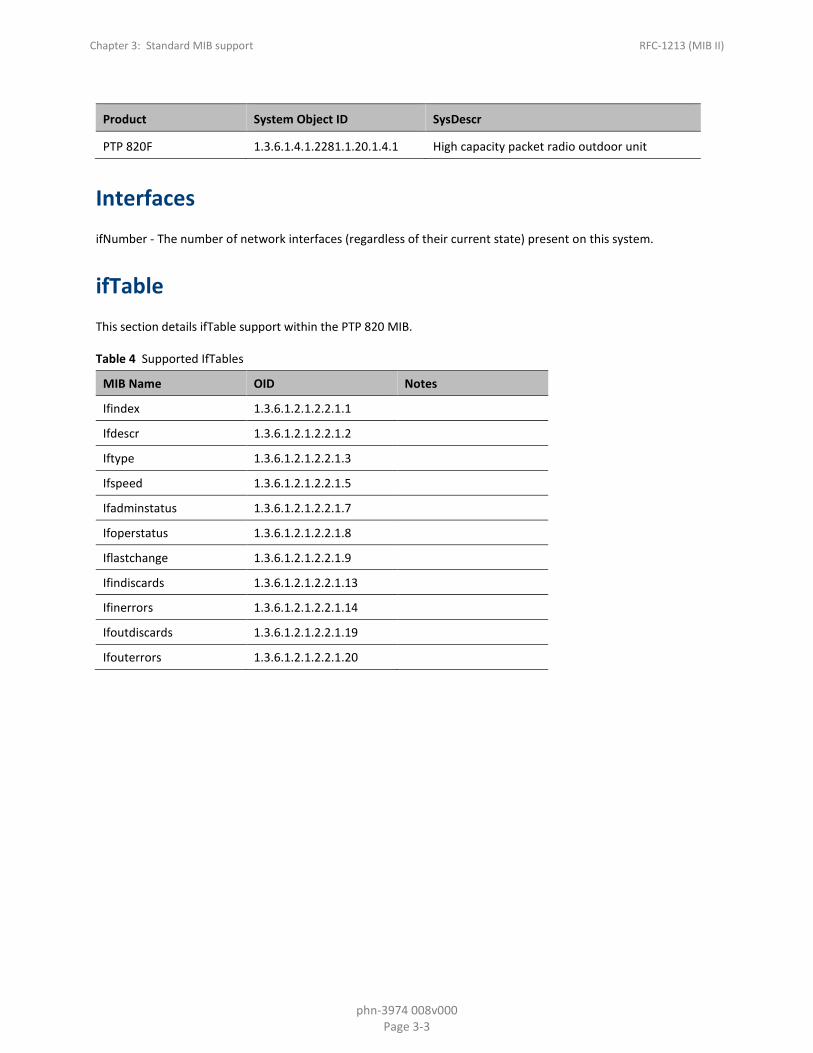
PTP 820F 1.3.6.1.4.1.2281.1.20.1.4.1 High capacity packet radio outdoor unit
Interfaces ifNumber - The number of network interfaces (regardless of their current state) present on this system.
ifTable This section details ifTable support within the PTP 820 MIB.
Table 4 Supported IfTables
MIB Name OID Notes
Ifindex 1.3.6.1.2.1.2.2.1.1
Ifdescr 1.3.6.1.2.1.2.2.1.2
Iftype 1.3.6.1.2.1.2.2.1.3
Ifspeed 1.3.6.1.2.1.2.2.1.5
Ifadminstatus 1.3.6.1.2.1.2.2.1.7
Ifoperstatus 1.3.6.1.2.1.2.2.1.8
Iflastchange 1.3.6.1.2.1.2.2.1.9
Ifindiscards 1.3.6.1.2.1.2.2.1.13
Ifinerrors 1.3.6.1.2.1.2.2.1.14
Ifoutdiscards 1.3.6.1.2.1.2.2.1.19
Ifouterrors 1.3.6.1.2.1.2.2.1.20

Chapter 3: Standard MIB support RFC-1213 (MIB II)
phn-3974 008v000 Page 3-4
IfXTable Table 5 Standard IfXtable support
MIB Name OID Notes
ifName 1.3.6.1.2.1.31.1.1.1.1
ifInMulticastPkts 1.3.6.1.2.1.31.1.1.1.2
ifInBroadcastPkts 1.3.6.1.2.1.31.1.1.1.3
ifOutMulticastPkts 1.3.6.1.2.1.31.1.1.1.4
ifOutBroadcastPkts 1.3.6.1.2.1.31.1.1.1.5
ifHCInOctets 1.3.6.1.2.1.31.1.1.1.6
ifHCOutOctets 1.3.6.1.2.1.31.1.1.1.10
ifHighSpeed 1.3.6.1.2.1.31.1.1.1.15
ifAlias 1.3.6.1.2.1.31.1.1.1.18
Chapter 3: Standard MIB support RFC-1213 (MIB II)
phn-3974 008v000 Page 3-5
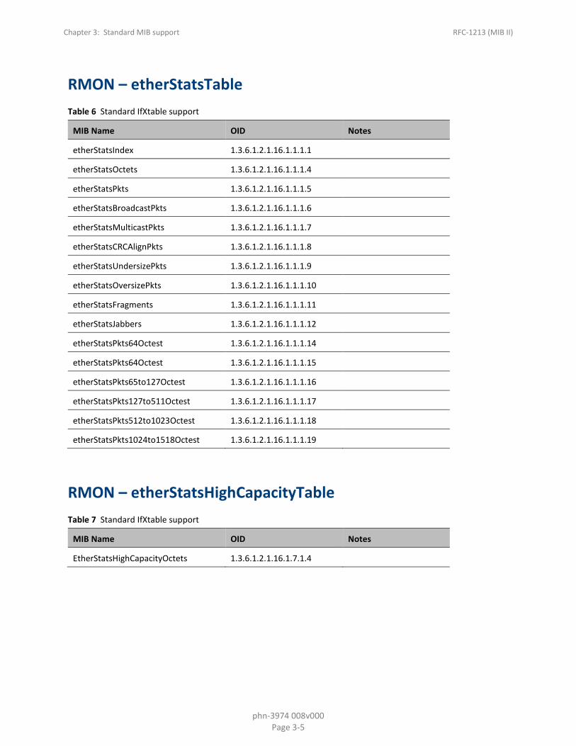
RMON – etherStatsTable Table 6 Standard IfXtable support
MIB Name OID Notes
etherStatsIndex 1.3.6.1.2.1.16.1.1.1.1
etherStatsOctets 1.3.6.1.2.1.16.1.1.1.4
etherStatsPkts 1.3.6.1.2.1.16.1.1.1.5
etherStatsBroadcastPkts 1.3.6.1.2.1.16.1.1.1.6
etherStatsMulticastPkts 1.3.6.1.2.1.16.1.1.1.7
etherStatsCRCAlignPkts 1.3.6.1.2.1.16.1.1.1.8
etherStatsUndersizePkts 1.3.6.1.2.1.16.1.1.1.9
etherStatsOversizePkts 1.3.6.1.2.1.16.1.1.1.10
etherStatsFragments 1.3.6.1.2.1.16.1.1.1.11
etherStatsJabbers 1.3.6.1.2.1.16.1.1.1.12
etherStatsPkts64Octest 1.3.6.1.2.1.16.1.1.1.14
etherStatsPkts64Octest 1.3.6.1.2.1.16.1.1.1.15
etherStatsPkts65to127Octest 1.3.6.1.2.1.16.1.1.1.16
etherStatsPkts127to511Octest 1.3.6.1.2.1.16.1.1.1.17
etherStatsPkts512to1023Octest 1.3.6.1.2.1.16.1.1.1.18
etherStatsPkts1024to1518Octest 1.3.6.1.2.1.16.1.1.1.19
RMON – etherStatsHighCapacityTable Table 7 Standard IfXtable support
MIB Name OID Notes
EtherStatsHighCapacityOctets 1.3.6.1.2.1.16.1.7.1.4

Chapter 3: Standard MIB support RFC-1213 (MIB II)
phn-3974 008v000 Page 3-6
IfIndex The IfIndex has the following structure:
Table 8 IfIndex Structure
IfIndex (32 bit)
Bit # 31 (MSB) 30..28 27..0 (LSB)
Function Reserved = 0 Format Format Dependant Structure
Bit Width 1 bit 3 bits 28 bits
Table 9 IfIndex “Format” Field Optional Values
Format Value 7..4 3 2 1 0
Function Reserved NG Service Format
Reserved NG Interface Format
Legacy
NG Interface Format Table 10 NG Interface Format IfIndex Structure
IfIndex (32 bit)
Bit # 31 (MSB) 30..28 27..17 16..13 12..6 5..0 (LSB)
Function Reserved = 0 Format=1 Instance Interface Functional Type
Slot Port
Bit Width 1 bit 3 bits 11 bit 4 bits 7 bits 6 bits

Chapter 3: Standard MIB support RFC-1213 (MIB II)
phn-3974 008v000 Page 3-7
Table 11 IfIndex “Interface Functional Type” Field Optional Values
Format Type Value
6 5 4 3 2 1 0
Function TDM Smart TDM Synch Mng Radio Ethernet N/A
Format Type Value
15 14 ..10 9 8 7
Function Group Reserved FAN PDC STM-1/ OC-3
Table 12 IfIndex “Slot” Field Optional Values
Virtual Slots
Slot Value 127 126..71 70 69 68 67 66 65 64
Function IVM Reserved MIMO PWE Protection
Radio Protection
XPIC ABC MR LAG
Physical Slots
Slot Value 63 … 55 51 50 … 2 1 0
Function Slot-63 … … Slot-2 Slot-1
Table 13 IfIndex “Port/Group” Field Optional Values
Port Value 63 62 …. 2 1 0
Function Port-63 Port-62 …. Port-2 Port-1 N/A
NG Service Format Table 14 NG Service Format IfIndex Structure
IfIndex (32 bit)
Bit # 31 (MSB) 30..28 27..24 23..12 11..7 6..4 (LSB) 3..0(LSB)
Function Reserved = 0
Format=3 Service type=1
Service Id Service Point id
MEG Level Reserved=0
Bit Width 1 bit 3 bits 4 bit 12 bits 5 bits 3bits 4 bits

Chapter 3: Standard MIB support RFC-1213 (MIB II)
phn-3974 008v000 Page 3-8
Table 15 Service Type
Service Type Value 15..2 1 0
Function Reserved Soam MEP N/A
• Service Id – Value from 1 to 4096
• Service Point id – Value from 1 to 32
• MEG level – Value from 1 to 7
Other parameters and tables The following parameters and tables are answered by the CPU interface of the network element.
Table 16 Other Supported Networking Parameters
Parameters Supported by PTP 820 MIB AT (atTable) Supported
IP Supported (also defined in RFC 2011)
ICMP Supported
TCP Supported (also defined in RFC 2012)
UDP Supported (also defined in RFC 2013)

Chapter 3: Standard MIB support Multiple Spanning Tree Protocol (MSTP)
phn-3974 008v000 Page 3-9
Multiple Spanning Tree Protocol (MSTP)
PTP 820G, PTP 820F supports the following standard MIBs for Multiple Spanning Tree Protocol (MSTP):
• IEEE8021-MSTP-MIB-201103230000Z
• IEEE8021-SPANNING-TREE-MIB-200810150000Z
These MIBs are derived from IETF BRIDGE_MIB (RFC-4188).
There are two additional MSTP related MIBs which are part of the private MIB, since they are not defined as part of the standard MSTP MIB:
• genEquipProtocolsMstpGeneralAttributesTable
• genEquipProtocolsMstpCountersTable
For more details, refer to Private MIB Reference on page 2-1.

Chapter 3: Standard MIB support Traps ID
phn-3974 008v000 Page 3-10
Traps ID
The following table describes the Trap ID definition in NETWORK-MIB.
Table 17 Network MIB
SNMP Version Trap type Name ID
V.1 Alarm / Event alarmNGTrap 2281.0.2000
V.1 heartbeat generalNGV3Trap 2281.11.2000
V.2/3 Alarm / Event heartbeatNGTrap 2281.0.2001
V.2/3 heartbeat heartbeatNGV3Trap 2281.11.2001
Trap Var Bind Table 18 Trap Var-Bind Parameters
SNMP
Version
Trap type Name OID Comments
V.2/3 Alarm / Event
sysUpTime 1.3.6.1.2.1.1.3 The time (in hundredths of a second) since the network management portion of the system was last re-initialized.
V.2/3 Alarm / Event
snmpTrapOID 1.3.6.1.6.3.1.1.4.1 The authoritative identification of the notification currently being sent (Trap ID).
V.1/2/3 Alarm / Event / heartbeat
genEquipCurrentAlarmCounter
1.3.6.1.4.1.2281.10.3.1.2.1.1
Contains the information of a RAISED trap.
V.1/2/3 Alarm / Event
genEquipCurrentAlarmRaisedTimeT
1.3.6.1.4.1.2281.10.3.1.2.1.2
Time the alarm was raised.
V.1/2/3 Alarm / Event
genEquipNetworkAgentIp
1.3.6.1.4.1.2281.10.2.3
Agent IP address (IP V4)
V.1/2/3 Alarm / Event
genEquipCurrentAlarmId 1.3.6.1.4.1.2281.10.3.1.2.1.3
Alarm ID.
For a complete list of Alarm IDs, see Alarms on page 44.

Chapter 3: Standard MIB support Traps ID
phn-3974 008v000 Page 3-11
SNMP
Version
Trap type Name OID Comments
V.1/2/3 Alarm / Event
genEquipCurrentAlarmDesc
1.3.6.1.4.1.2281.10.3.1.2.1.9
Description of the alarm.
For a complete list of alarms and their descriptions, see Alarms on page 44.
V.1/2/3 Alarm / Event
genEquipCurrentAlarmIfIndex
1.3.6.1.4.1.2281.10.3.1.2.1.7
Interface index that indicates where the alarm occurred.
V.1/2/3 Alarm / Event
genEquipCurrentAlarmInstance
1.3.6.1.4.1.2281.10.3.1.2.1.5
Alarm Instance.
For most alarms, this parameter is not used because this information is reflected in the ifindex.
V.1/2/3 Alarm / Event
genEquipCurrentAlarmSeverity
1.3.6.1.4.1.2281.10.3.1.2.1.6
Severity of the current alarm. Possible values are:
Indeterminate (0)
Critical (1)
Major (2)
Minor (3)
Warning (4)
Cleared (5)
V.1/2/3 Alarm / Event
genEquipCurrentAlarmState
1.3.6.1.4.1.2281.10.3.1.2.1.12
Indicates whether the alarm is raised or cleared. Possible values are:
Alarm cleared (0)
Alarm raised (1)
Event (2)
V.1/2/3 Alarm / Event
genEquipCurrentAlarmUserText
1.3.6.1.4.1.2281.10.3.1.2.1.15
User-defined alarm text. Does not need to contain a value.
V.1/2/3 Alarm / Event / heartbeat
genEquipTrapCfgMgrCLLI 1.3.6.1.4.1.2281.10.3.2.1.1.9
Configures the Common Language Location Identifier (CLLI). Does not need to contain a value.
V.1/2/3 Alarm / Event
genEquipNetworkAgentIpV6
1.3.6.1.4.1.2281.10.2.7
Agent IP address (IP V6)

phn-3974_008v000 Page 4-1
Chapter 4: Common Tasks
The task descriptions in this chapter are presented from a functional perspective and represent how the commands and parameters would be used according to a common workflow.
Each task description contains a step by step procedure that explains how to use the MIB objects to perform that task.
This chapter includes:
• Software Management
• Configuration file management
• Enabling and configuring traps
• Viewing current alarms
• Performance monitoring and counters
• Managing radio configuration

Chapter 4: Common Tasks Software Management
phn-3974 008v000 Page 4-2
Software Management
Downloading a software version
Software download procedural overview This section describes the required procedure to download the software package for the PTP 820 unit.
To download and install a new software version:
1. Configure the FTP parameters using table genEquipMngSwFileTransferTable.
2. Download the desired software files with genEquipMngSwOperationOperation command using download (1) parameter. The new software files are added to the library.
3. Verify the download status in the genEquipMngSwFileTransferStatusResult object, until status is download success (4).
The progress of the process (in percentage) can also be tracked using genEquipMngSwFileTransferPercentageDone.
4. Install the genEquipMngSwOperationOperation command using install (2) parameter. The software is installed in the system.
5. Verify the installation status in the genEquipMngSwInstallStatusResult object, until status is installation success (4).
The progress of the process (in percentage) can also be tracked using genEquipMngSwInstall PercentageDone.
o The PTP 820 unit automatically resets and applies the changes to all modules.
Verify that the unit is using the downloaded version. The version numbers are located in the genEquipMngSwIDUVersionsTabletable.
Configuring FTP parameters The new software versions are located on a remote FTP server. In order to download a new software version, the server parameters must be configured.
Table 19 MIB Objects for Configuring FTP Parameters
Parameter Function OID
genEquipMngSwFileTransferProtocol
Chooses the protocol to be used (FTP, SFTP, HTTP, HTTPS).
1.3.6.1.4.1.2281.10.4.1.18.1.2
genEquipMngSwFileTransferUserName
User name for access to the configuration file location.
1.3.6.1.4.1.2281.10.4.1.18.1.3
genEquipMngSwFileTransferPassword
Password for the remote software update server.
1.3.6.1.4.1.2281.10.4.1.18.1.4

Chapter 4: Common Tasks Software Management
phn-3974 008v000 Page 4-3
Parameter Function OID
genEquipMngSwFileTransferAddress
IP address of the computer where software version files are to be taken from.
1.3.6.1.4.1.2281.10.4.1.18.1.5
genEquipMngSwFileTransferPath Location of the files in the external server.
1.3.6.1.4.1.2281.10.4.1.18.1.6
Managing software There are two commands that help users to control the software versions: Download and install.
The genEquipMngSwOperationOperation MIB object has four values which execute four different commands:
• No action (0)
• Download (1) – download packages from the remote server.
• Install (2) –install the downloaded packages.
• Update backup (3) –Not supported
• Swap boot section (4) – Not supported
• Abort timer (5) – Not supported
Table 20 Managing software versions MIB object
Parameter Function OID
genEquipMngSwOperationOperation
Commands that can be executed to manage software versions:
No action (0)
Download (1) – download packages from the remote server.
install (2) –install the downloaded packages.
update backup (3) – Not supported
Swap boot section (4) – Not supported
Abort timer (5) – Not supported
1.3.6.1.4.1.2281.10.4.1.21.1
Checking software status The status of the most recent software download and installation can be checked.
The genEquipMngSwFileTransferStatusTable display the following values to indicate the file transfer status:
• Ready (0)
• download-started (1)
• verifying-download-files (2)
• Download-in-progress (3)
• download-success (4)
Chapter 4: Common Tasks Software Management
phn-3974 008v000 Page 4-4
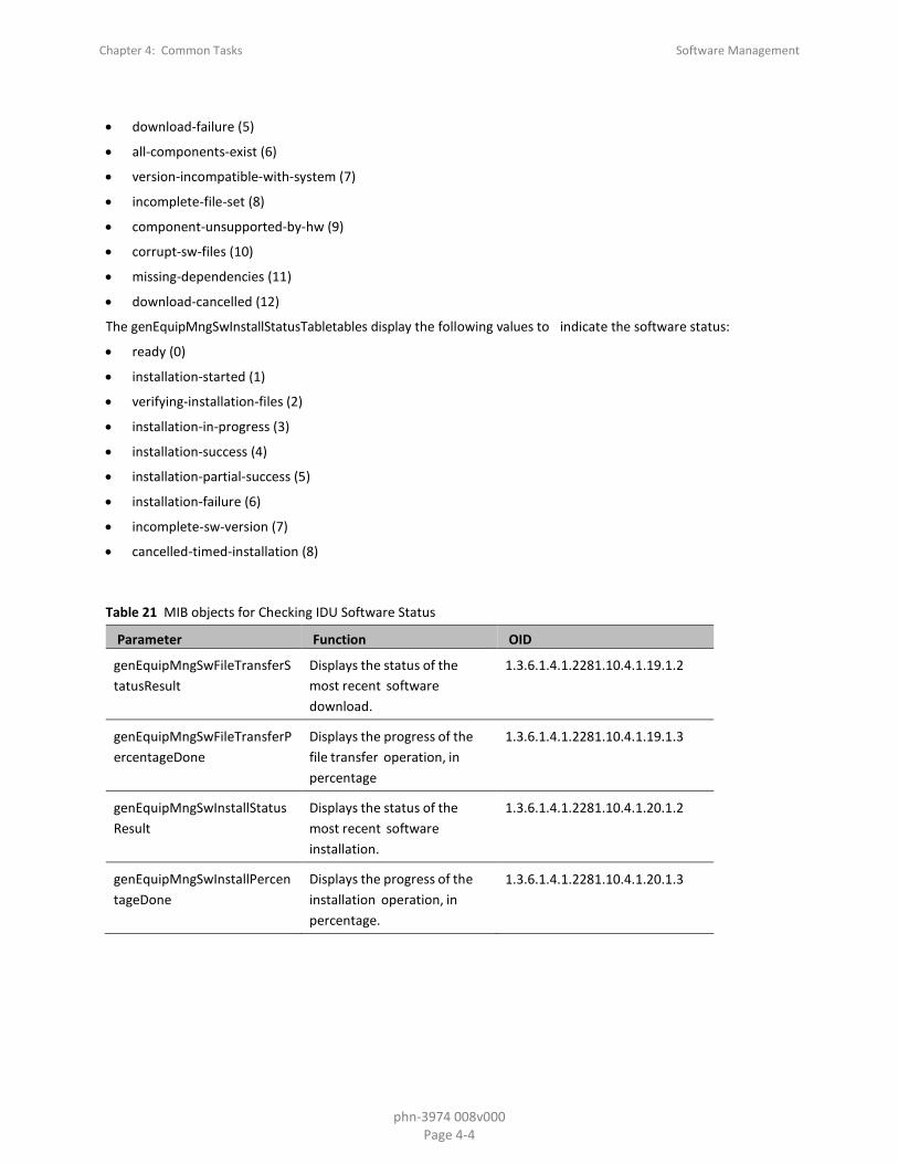
• download-failure (5)
• all-components-exist (6)
• version-incompatible-with-system (7)
• incomplete-file-set (8)
• component-unsupported-by-hw (9)
• corrupt-sw-files (10)
• missing-dependencies (11)
• download-cancelled (12)
The genEquipMngSwInstallStatusTabletables display the following values to indicate the software status:
• ready (0)
• installation-started (1)
• verifying-installation-files (2)
• installation-in-progress (3)
• installation-success (4)
• installation-partial-success (5)
• installation-failure (6)
• incomplete-sw-version (7)
• cancelled-timed-installation (8)
Table 21 MIB objects for Checking IDU Software Status
Parameter Function OID
genEquipMngSwFileTransferStatusResult
Displays the status of the most recent software download.
1.3.6.1.4.1.2281.10.4.1.19.1.2
genEquipMngSwFileTransferPercentageDone
Displays the progress of the file transfer operation, in percentage
1.3.6.1.4.1.2281.10.4.1.19.1.3
genEquipMngSwInstallStatusResult
Displays the status of the most recent software installation.
1.3.6.1.4.1.2281.10.4.1.20.1.2
genEquipMngSwInstallPercentageDone
Displays the progress of the installation operation, in percentage.
1.3.6.1.4.1.2281.10.4.1.20.1.3

Chapter 4: Common Tasks Software Management
phn-3974 008v000 Page 4-5
Upgrading the RFU software version
Note
This procedure is not necessary for PTP 820C and PTP 820S units. In these units, all the software modules are upgraded via the installation process described above.
The software package that is downloaded also includes the necessary software to upgrade the RFUs.
When upgrading the software version for the RFUs, each RFU must be upgraded individually.
Upgrading the RFU and IDU are different procedures. When the IDU is upgraded, the main unit automatically applies the necessary upgrade to all of the modules.
RFU software upgrade procedural overview To install a new software version for the RFU:
1. If the RFU version is not included in the IDU’s installed software package, download and install the desired relevant software files package (refer to Downloading a software version on page 4-2).
The available versions are found in table
genEquipRfuAvailableVersionsTable.
2. In order to install the RFU version for a specific slot Install and upgrade the RFU the new software version use the genEquipRfuSwInstallOperation genEquipRfuUploadSwCommand update version-from-bundle Upload SW
(1) command.
3. In order to upgrade the RFU in a slot which has already been updated with the correct version, use the genEquipRfuSwInstallOperation update- install-existing-version (2) command.
The installed versions are found in table
genEquipRfuInstalledVersionsTable.
Verify that the upgrade status in the genEqipRfuUploadSwStatus object. The status begins as Load Start (2) and continues with Load Send Block (3).
4. Verify that the upgrade status has completed in the
genEquipRfuSwStatusCurrentState object. The status should be installation-success Load Done (4).
Percentage compleed can also be monitored using enEquipRfuSwStatusProgress.
5. Verify that the RFU is using the new software version. The version numbers are located in the genEquipRfuRunningVersionsTable object.
6. Repeat steps 2-5 of this procedure for each RFU in the system as necessary.
Upgrading RFU software version The genEquipRfuSwInstallOperation MIB object has the following values which control the software upgrade for the RFU:
• No Operation (0) – performs no action
• Upload Swupdate version from bundle (1) – uploads newer packages to the RFUupdates the RFU version in each slot and updates the RFU
• Install existing version (2) – updates the RFU with the version held at the slot
Chapter 4: Common Tasks Software Management
phn-3974 008v000 Page 4-6
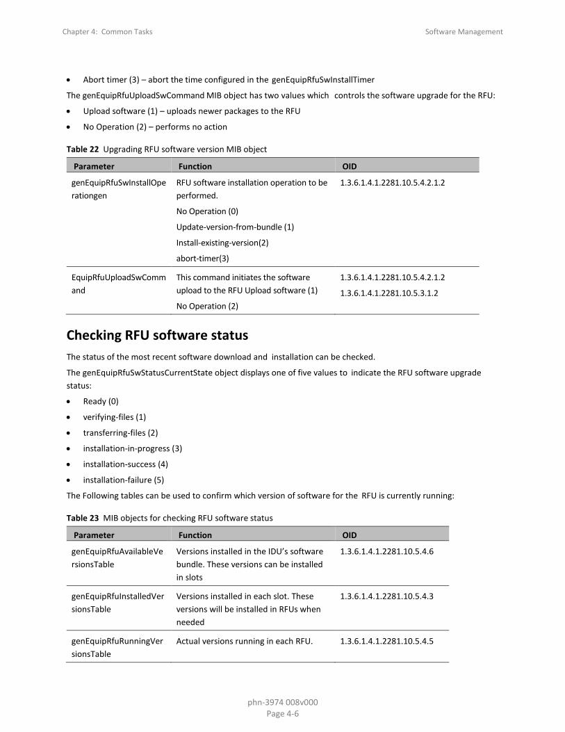
• Abort timer (3) – abort the time configured in the genEquipRfuSwInstallTimer
The genEquipRfuUploadSwCommand MIB object has two values which controls the software upgrade for the RFU:
• Upload software (1) – uploads newer packages to the RFU
• No Operation (2) – performs no action
Table 22 Upgrading RFU software version MIB object
Parameter Function OID
genEquipRfuSwInstallOperationgen
RFU software installation operation to be performed.
No Operation (0)
Update-version-from-bundle (1)
Install-existing-version(2)
abort-timer(3)
1.3.6.1.4.1.2281.10.5.4.2.1.2
EquipRfuUploadSwCommand
This command initiates the software upload to the RFU Upload software (1)
No Operation (2)
1.3.6.1.4.1.2281.10.5.4.2.1.2
1.3.6.1.4.1.2281.10.5.3.1.2
Checking RFU software status The status of the most recent software download and installation can be checked.
The genEquipRfuSwStatusCurrentState object displays one of five values to indicate the RFU software upgrade status:
• Ready (0)
• verifying-files (1)
• transferring-files (2)
• installation-in-progress (3)
• installation-success (4)
• installation-failure (5)
The Following tables can be used to confirm which version of software for the RFU is currently running:
Table 23 MIB objects for checking RFU software status
Parameter Function OID
genEquipRfuAvailableVersionsTable
Versions installed in the IDU’s software bundle. These versions can be installed in slots
1.3.6.1.4.1.2281.10.5.4.6
genEquipRfuInstalledVersionsTable
Versions installed in each slot. These versions will be installed in RFUs when needed
1.3.6.1.4.1.2281.10.5.4.3
genEquipRfuRunningVersionsTable
Actual versions running in each RFU. 1.3.6.1.4.1.2281.10.5.4.5

Chapter 4: Common Tasks Configuration file management
phn-3974 008v000 Page 4-7
Configuration file management
The PTP 820 MIB file allows to view the current configuration of the PTP 820 unit. It also allows to create backup files of the system configuration and upload them to a FTP server. The archived backup file can be downloaded for later use.
System configuration FTP settings The archived system configurations are stored on a FTP server. The server saves the file that contains the existing configuration. The system configuration file can be downloaded and installed on the desired system when necessary.
The FTP settings must be set in the MIB file before using FTP server.
Software download FTP parameters are located in genEquipMngCfgFileTransferTable.
Table 24 MIB objects for configuring FTP settings
Parameter Function OID
genEquipMngCfgFileTransferProtocol
Configures the protocol to be used (FTP, SFTP, HTTP, HTTPS)
1.3.6.1.4.1.2281.10.4.2.11.1.2
genEquipMngCfgFileTransferUserName
Configures the required user name for the FTP server.
1.3.6.1.4.1.2281.10.4.2.11.1.3
genEquipMngCfgFileTransferPassword
Configures the required password for the FTP server.
1.3.6.1.4.1.2281.10.4.2.11.1.4
genEquipMngCfgFileTransferAddress
Configures the host IP address of the FTP server.
1.3.6.1.4.1.2281.10.4.2.11.1.5
genEquipMngCfgFileTransferPath
Configures the path of the host directory on the FTP server.
1.3.6.1.4.1.2281.10.4.2.11.1.6
genEquipMngCfgFileTransferFileName
Configures the filename to be used in the server.
1.3.6.1.4.1.2281.10.4.2.11.1.7

Chapter 4: Common Tasks Configuration file management
phn-3974 008v000 Page 4-8
Creating and uploading backup configuration archives To create a backup file which contains all the details of the current PTP 820 configuration, use genEquipMngCfgOperationOperation with a value of (1) Backup.
Table 25 Creating Configuration Archive MIB Object
Parameter Function OID
genEquipMngCfgOperationOperation
Executes the Backup system configuration commands:
Invalid-operation (0)
Backup (1)
1.3.6.1.4.1.2281.10.4.2.13.1.2
Procedural overview of uploading a system configuration This section describes the required procedure to save the current system configuration of the PTP 820 unit and export it to an FTP server.
To save and upload the current system configuration:
1 Verify the FTP settings.
2 Create the archive files of the current system configuration. The genEquipMngCfgOperationOperation with Backup (1) command creates an archive file. Up to three files can be stored, each identified by parameter genEquipMngCfgOperationFileNumber.
3 Verify that the configuration file generation has succeeded in the genEquipMngCfgBackupStatus object. The status should be download- success (3).
4 Upload the archive files to the FTP server with the genEquipMngCfgOperationOperation with export (5) command.5
Verify that the upload to the FTP server has succeeded in the genEquipMngCfgFileTransferStatus object. The status should be download success (4).
Exporting an archived configuration To export an archived configuration of the PTP 820 unit to an FTP server use genEquipMngCfgOperationOperation with a value of (5) export.
Table 26 Uploading Archived Configuration MIB Object
Parameter Function OID
genEquipMngCfgOperation Operation
Executes the Backup system configuration commands:
Export (1)
1.3.6.1.4.1.2281.10.4.2.13.1.2
Chapter 4: Common Tasks Configuration file management
phn-3974 008v000 Page 4-9
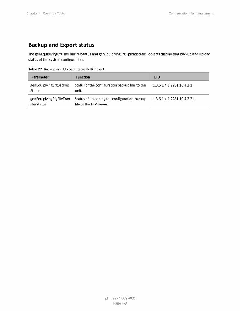
Backup and Export status The genEquipMngCfgFileTransferStatus and genEquipMngCfgUploadStatus objects display that backup and upload status of the system configuration.
Table 27 Backup and Upload Status MIB Object
Parameter Function OID
genEquipMngCfgBackupStatus
Status of the configuration backup file to the unit.
1.3.6.1.4.1.2281.10.4.2.1
genEquipMngCfgFileTransferStatus
Status of uploading the configuration backup file to the FTP server.
1.3.6.1.4.1.2281.10.4.2.21
Chapter 4: Common Tasks Enabling and configuring traps
phn-3974 008v000 Page 4-10
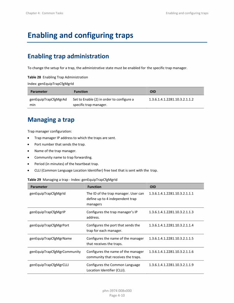
Enabling and configuring traps
Enabling trap administration To change the setup for a trap, the administrative state must be enabled for the specific trap manager.
Table 28 Enabling Trap Administration
Index: genEquipTrapCfgMgrId
Parameter Function OID
genEquipTrapCfgMgrAdmin
Set to Enable (2) in order to configure a specific trap manager.
1.3.6.1.4.1.2281.10.3.2.1.1.2
Managing a trap Trap manager configuration:
• Trap manager IP address to which the traps are sent.
• Port number that sends the trap.
• Name of the trap manager.
• Community name to trap forwarding.
• Period (in minutes) of the heartbeat trap.
• CLLI (Common Language Location Identifier) free text that is sent with the trap.
Table 29 Managing a trap - Index: genEquipTrapCfgMgrId
Parameter Function OID
genEquipTrapCfgMgrId
The ID of the trap manager. User can define up to 4 independent trap managers
1.3.6.1.4.1.2281.10.3.2.1.1.1
genEquipTrapCfgMgrIP Configures the trap manager’s IP address.
1.3.6.1.4.1.2281.10.3.2.1.1.3
genEquipTrapCfgMgrPort Configures the port that sends the trap for each manager.
1.3.6.1.4.1.2281.10.3.2.1.1.4
genEquipTrapCfgMgrName Configures the name of the manager that receives the traps.
1.3.6.1.4.1.2281.10.3.2.1.1.5
genEquipTrapCfgMgrCommunity Configures the name of the manager community that receives the traps.
1.3.6.1.4.1.2281.10.3.2.1.1.6
genEquipTrapCfgMgrCLLI Configures the Common Language Location Identifier (CLLI).
1.3.6.1.4.1.2281.10.3.2.1.1.9

Chapter 4: Common Tasks Enabling and configuring traps
phn-3974 008v000 Page 4-11
Parameter Function OID
genEquipTrapCfgMgrHeartbeatPeriod
Configures the minute interval between each heartbeat.
1.3.6.1.4.1.2281.10.3.2.1.1.10

Chapter 4: Common Tasks Viewing current alarms
phn-3974 008v000 Page 4-12
Viewing current alarms
Alarm date and time The date and time of an alarms can be viewed.
Table 30 Alarm date and time MIB object
Parameter Function OID
genEquipCurrentAlarmRaisedTimeT
Time the alarm was raised. 1.3.6.1.4.1.2281.10.3.1.2.1.2
Alarm severity The alarm severity can be checked.
Table 31 Alarm severity MIB object
Parameter Function OID
genEquipCurrentAlarmSeverity
Severity of the current alarm: Indeterminate (0)
Critical (1)
Major (2)
Minor (3)
Warning (4)
Cleared (5)
1.3.6.1.4.1.2281.10.3.1.2.1.6
Affected module The module which is affected by the alarm, can be viewed.
Table 32 Affected Module MIB Object
Parameter Function OID
genEquipCurrentAlarmModule
Module of the alarm. 1.3.6.1.4.1.2281.10.3.1.2.1.8

Chapter 4: Common Tasks Viewing current alarms
phn-3974 008v000 Page 4-13
Alarm description The description of the alarm can viewed.
Table 33 Alarm Description MIB Object
Parameter Function OID
genEquipCurrentAlarmDesc Description of the alarm. 1.3.6.1.4.1.2281.10.3.1.2.1.9
Probable cause The probable cause for the alarm can be viewed.
Table 34 Probable Alarm Cause MIB Object
Parameter Function OID
genEquipCurrentAlarmProbableCause Probable cause of the alarm. 1.3.6.1.4.1.2281.10.3.1.2.1.10
Corrective actions The recommended corrective actions to solve the problem that caused the alarm, can be viewed.
Table 35 Corrective Actions MIB Object
Parameter Function OID
genEquipCurrentAlarmCorrectiveActions
Corrective actions that should be taken
1.3.6.1.4.1.2281.10.3.1.2.1.11

Chapter 4: Common Tasks Performance monitoring and counters
phn-3974 008v000 Page 4-14
Performance monitoring and counters
The MIB file to configure and retrieve the performance monitoring data of the PTP 820 unit can be used.
Clearing all performance counter data The genEquipPmClear command to clears the values for all of the performance monitoring tables can be used.
The Object ID is: 1.3.6.1.4.1.2281.10.6.3.1.

Chapter 4: Common Tasks Managing radio configuration
phn-3974 008v000 Page 4-15
Managing radio configuration
The MIB file to manage the radio configuration data of the unit can be used.
Setting the radio threshold This section explains how to set the Radio thresholds. After the thresholds are set, the system records the number of seconds that each of them was exceeded.
Table 36 Setting RSL Threshold
Parameter Function OID
genEquipPmRadioThresholdMSE Configures which PM table is accessed.
1.3.6.1.4.1.2281.10.6.3.4.5.1.1
genEquipPmRadioThresholdRSL1 Configures which interface or port is monitored.
1.3.6.1.4.1.2281.10.6.3.4.5.1.2
genEquipPmRadioThresholdRSL2 Configures the time interval of the PM.
1.3.6.1.4.1.2281.10.6.3.4.5.1.3
GenEquipPmRadioThresholdTSL Percentage of received frames that contained errors.
1.3.6.1.4.1.2281.10.6.3.4.5.1.5
genEquipPmRadioThresholdXPI Maximum Ethernet throughput measured during the last interval.
1.3.6.1.4.1.2281.10.6.3.4.3.1.1.4
Setting the traffic PM thresholds This section explains how to set radio capacity, throughput, and utilization PM thresholds. After the thresholds are set, the system records the number of seconds that each of them was exceeded.
Table 37 Setting Traffic PMThresholds
Parameter Function OID
genEquipRadioCompNGCfgCapacityPmThreshold
Configures the threshold for capacity PMs, in Mbps. The range of values is 0 to 4294967295. The default value for is 1000.
1.3.6.1.4.1.2281.10.7.5.4.1.1.6

Chapter 4: Common Tasks Managing radio configuration
phn-3974 008v000 Page 4-16
enEquipRadioCompNGCfgThroughputPmThreshold
Configures the threshold for throughput PMs, in Mbps. The range of values is 0 to 4294967295. The default value for is 1000.
1.3.6.1.4.1.2281.10.7.5.4.1.1.7
genEquipRadioCompNGCfgUtilizationPmThreshold
Configures the radio capacity utilization threshold, in % (1-100). The default value for is 100.
1.3.6.1.4.1.2281.10.7.5.4.1.1.8

Chapter 5: MIB Revision History Managing radio configuration
phn-3974 008v000 Page 5-17
Chapter 5: MIB Revision History
The following HTML files are included in a ZIP file with this MIB Reference:
• MIB_10.7_to_10.9_DIFF_IP-20N_IP-20A_IP-20LH.htm
• MIB_10.7_to_10.9_DIFF_IP-20F_IP-20G_IP-20GX.htm
• MIB_10.7_to_10.9_DIFF_IP-20_All-Outdoor.htm
These files list the MIB objects that were changed, added, or deleted from CeraOS 10.7 and CeraOS 10.7.5 to CeraOS 10.9.
Note: Release 10.7.5 used the same MIB files as Release 10.7.
In each of these DIFF files, the column on the left displays the 10.7/10.7.5 version of the object and the column on the right displays the 10.9 version of the object.
For rows in which the left column is empty, the object was added in Release 10.9.
For rows in which the right column is empty, the object was removed in Release 10.9.

Chapter 6: MIB error table (Reserved for future use) Managing radio configuration
phn-3974 008v000 Page 6-18
Chapter 6: MIB error table (Reserved for future use)
If there are any errors related to the PTP 820 unit, an errno is generated. Check the errno description in the following table to find a textual description of the error.
The table contains two columns:
• Errno Fault Number – genEquipFaultErrno (OID 1.3.6.1.4.1.2281.10.3.4)
• Errno Description – genEquipFaultErrDescr (OID 1.3.6.1.4.1.2281.10.3.5)
Chapter 7: Alarms Managing radio configuration
phn-3974 007v001 Page 7-1
Chapter 7: Alarms
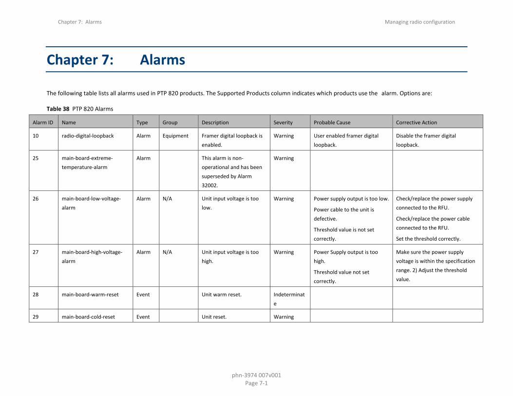
The following table lists all alarms used in PTP 820 products. The Supported Products column indicates which products use the alarm. Options are:
Table 38 PTP 820 Alarms
Alarm ID Name Type Group Description Severity Probable Cause Corrective Action
10 radio-digital-loopback Alarm Equipment Framer digital loopback is enabled.
Warning User enabled framer digital loopback.
Disable the framer digital loopback.
25 main-board-extreme-temperature-alarm
Alarm This alarm is non-operational and has been superseded by Alarm 32002.
Warning
26 main-board-low-voltage-alarm
Alarm N/A Unit input voltage is too low.
Warning Power supply output is too low.
Power cable to the unit is defective.
Threshold value is not set correctly.
Check/replace the power supply connected to the RFU.
Check/replace the power cable connected to the RFU.
Set the threshold correctly.
27 main-board-high-voltage-alarm
Alarm N/A Unit input voltage is too high.
Warning Power Supply output is too high.
Threshold value not set correctly.
Make sure the power supply voltage is within the specification range. 2) Adjust the threshold value.
28 main-board-warm-reset Event Unit warm reset. Indeterminate
29 main-board-cold-reset Event Unit reset. Warning

Chapter 7: Alarms Managing radio configuration
phn-3974 007v001 Page 7-2
Alarm ID Name Type Group Description Severity Probable Cause Corrective Action
30 main-board-poe-low-voltage-alarm
Alarm POE input voltage is too low
Warning PoE supply output is too low.
PoE cable to the unit is defective.
Make sure the PoE voltage is within the specification range.
31 Event Change Remote request was sent
Major
32 Event Protection switchover due to remote request
Major
33 protection-mimo-misconfiguration-alarm
Alarm Major Unit Redundancy and MIMO 4x4 cannot operate simultaneously.
100 lag-degraded Alarm Equipment LAG is not fully functional - LAG Degraded.
Major At least one interface is not connected or configured to admin down.
If one of the members is radio it might be in operational state down due to channel fading
Check the physical connections.
Verify that the Admin state of all the LAG members is up.
Verify the operational state of all radio members in the LAG.
101 lag-down Alarm Equipment LAG operational state is down
Critical The LAG group is not operational.
Check the physical connections and administrative status on both sides of the link of all interfaces that are members of the LAG Group.
Check the physical connections of all interfaces that are members of the LAG Group.
102 ethernet-loopback-active-alarm
Alarm Equipment Loopback is active Major Ethernet loopback is active. Wait for expiration of the loopback timeout, or manually disable the loopback.

Chapter 7: Alarms Managing radio configuration
phn-3974 007v001 Page 7-3
Alarm ID Name Type Group Description Severity Probable Cause Corrective Action
103 port-mirroring-is-active Alarm Equipment Slot X port XX is mirrored to slot Y port YY
Minor Mirroring is enabled by user configuration.
Disable mirroring.
120 port-speed-mismatch-alarm Alarm Equipment Port speed mismatch Major System reset is required after the port speed was changed.
Reset the system.
Change the port speed back to the previous value.
150 auto-state-propagation-interface-down-alarm
Alarm Communications
Auto-state-propagation is triggered
Major Failure of the radio/remote radio interface which is monitored for automatic state propagation causes automatic shutdown of the controlled interface.
Check adjacent local/remote radio interface for failure conditions that cause automatic state propagation.
200 protection-communication-down-alarm
Alarm Equipment Protection communication is down
Major Mate unit is absent/failure.
Protection cable is disconnected.
Unit failure.
Verify that the mate unit is up and running.
Check the state of the protection cable connection between the units.
Reset the mate unit
Replace the mate unit
201 protection-lockout-alarm Alarm Equipment Protection in Lockout State Major
202 protection-switch-command Event Equipment Protection switchover due to local failure
Major Check the unit.
Look for current alarms.
203 protection-mate-not-present-alarm
Alarm Equipment Mate does not exist Major Mate does not exist or cable unplugged.
Verify that the mate unit is up and running.
Verify that the protection cable is properly connected between the units.

Chapter 7: Alarms Managing radio configuration
phn-3974 007v001 Page 7-4
Alarm ID Name Type Group Description Severity Probable Cause Corrective Action
204 protection-hsb-insufficient-alarm
Alarm Equipment HSB insufficient configuration
Critical External Protection configured together with 1+1 HSB.
Remove External Protection or 1+1 HSB configuration.
307 tdm-link-up Event Equipment TDM interface is up Warning
308 tdm-link-down Event Equipment TDM interface is down Warning
401 TrafficPhyLocAlarm Alarm Equipment Loss of Carrier Major Cable disconnected.
Defective cable.
External equipment failure.
At both ends of the cable:
Check the cable connection.
Check the Admin state of the port.
Replace the cable.
Check external equipment.
407 ethernet-link-up Event Equipment Ethernet interface is up Warning Ethernet interface is back to being operational.
Notification. Corrective action is not required.
408 ethernet-link-down Event Equipment Ethernet interface is down Warning User commanded the interface to admin down.
Ethernet cable is disconnected.
Ethernet card is initializing.
External equipment failure.
Set the Ethernet interface admin State to Up.
Reconnect the Ethernet cable
Wait 30 seconds to allow the Ethernet card to complete its init.
Check external equipment.
Chapter 7: Alarms Managing radio configuration
phn-3974 007v001 Page 7-5
Alarm ID Name Type Group Description Severity Probable Cause Corrective Action
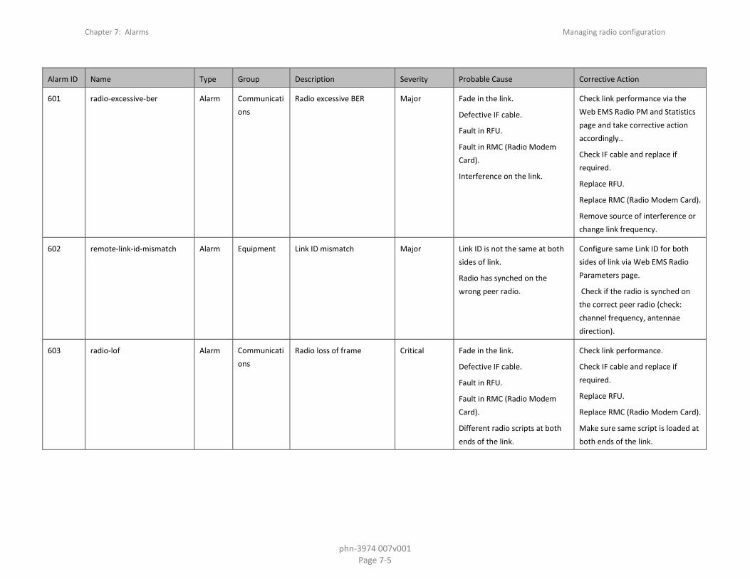
601 radio-excessive-ber Alarm Communications
Radio excessive BER Major Fade in the link.
Defective IF cable.
Fault in RFU.
Fault in RMC (Radio Modem Card).
Interference on the link.
Check link performance via the Web EMS Radio PM and Statistics page and take corrective action accordingly..
Check IF cable and replace if required.
Replace RFU.
Replace RMC (Radio Modem Card).
Remove source of interference or change link frequency.
602 remote-link-id-mismatch Alarm Equipment Link ID mismatch Major Link ID is not the same at both sides of link.
Radio has synched on the wrong peer radio.
Configure same Link ID for both sides of link via Web EMS Radio Parameters page.
Check if the radio is synched on the correct peer radio (check: channel frequency, antennae direction).
603 radio-lof Alarm Communications
Radio loss of frame Critical Fade in the link.
Defective IF cable.
Fault in RFU.
Fault in RMC (Radio Modem Card).
Different radio scripts at both ends of the link.
Check link performance.
Check IF cable and replace if required.
Replace RFU.
Replace RMC (Radio Modem Card).
Make sure same script is loaded at both ends of the link.

Chapter 7: Alarms Managing radio configuration
phn-3974 007v001 Page 7-6
Alarm ID Name Type Group Description Severity Probable Cause Corrective Action
604 radio-signal-degrade Alarm Communications
Radio signal degrade Minor Fade in the link.
Defective IF cable.
Fault in RFU.
Fault in RMC (Radio Modem Card).
Check link performance.
Check IF cable and replace if required.
Replace RFU.
Replace RMC (Radio Modem Card).
605 radio-link-up Event Equipment Radio interface is up Warning The radio interface is back to being operational.
No action is required.
606 radio-link-down Event Equipment Radio interface is down. Warning Radio interface is not operational:
User configured the radio interface to admin Down.
Loss of Frame (LOF) alarm is raised.
Excessive BER alarm is raised.
Radio card has not completed its init.
If required, set the radio interface admin State to Up.
Check if there is a reason for LOF / Excessive BER alarms.
Wait 30 seconds until the radio card finishes its init.
607 rfu-frequency-scanner-in-process
Alarm Equipment Frequency scanner in progress
Warning The frequency scanner is activated.
If required, stop the frequency scanner process.
801 corrupted-file-card-failure Alarm Equipment Corrupted inventory file Critical The inventory file is corrupted Reset the card.
Reinstall the software.
Replace the unit.
802 file-not-found Alarm Equipment Inventory file not found Warning The inventory file is missing Reset the system.
Reinstall the software.
Replace the unit

Chapter 7: Alarms Managing radio configuration
phn-3974 007v001 Page 7-7
Alarm ID Name Type Group Description Severity Probable Cause Corrective Action
803 sfp-rx-power-level-low Alarm Equipment SFP port RX power level is below the rx power level low threshold
Warning Remote SFP port Tx laser power is too low.
Fiber length is too long or fiber type doesn't fit the installed SFP.
Verify remote SFP Tx laser power is within range.
Check fiber type and length fit the installed SFP. If not, replace it with an appropriate one.
804 sfp-rx-power-level-high Alarm Equipment SFP port RX power level is above the rx power level high threshold
Warning Remote SFP Tx power is too high.
Add attenuator on Rx side.
805 sfp-tx-power-level-low Alarm Equipment SFP port TX power level is below the tx power level low threshold
Warning SFP transmit laser power is too low
Check laser Bias current. If it is too low, replace SFP.
806 sfp-tx-power-level-high Alarm Equipment SFP port TX power level is above the tx power level high threshold
Warning SFP laser Tx power is too high. Check laser Bias current and laser temperature values. If either of them is too high, replace SFP.
901 demo-license-alarm Alarm Equipment Demo mode is active Warning Demo mode has been activated by the user
Disable demo mode from the Activation Key Configuration page in the Web EMS.
902 license-demo-expired Event Equipment Demo mode is expired Warning
903 license-demo-start-by-user Event Processing Demo mode is started Warning
904 license-demo-stop-by-user Event Processing Demo mode is stopped Warning
905 license-load-fail Event Equipment Activation key loading failure
Major
906 license-load-successful Event Equipment Activation key loaded successfully
Warning

Chapter 7: Alarms Managing radio configuration
phn-3974 007v001 Page 7-8
Alarm ID Name Type Group Description Severity Probable Cause Corrective Action
907 license-violation-alarm Alarm Equipment Activation key violation Critical The current configuration does not match the activation-key-enabled feature set.
48 hours after an "activation-key-violation" alarm is raised, sanction mode is activated in which all alarms except the activation key violation alarm are cleared and no new alarms are raised.
Go to the "Activation Key Overview" page in the Web EMS to display a list of features and their activation key violation status.
Install a new activation key that enables all features and capacities that you require.
908 demo-license-about-to-expire-alarm
Alarm Equipment Demo mode is about to expire
Major Demo mode allowed period is about to end within 10 days
Disable demo mode and install a new valid activation key in the “Activation Key Configuration” page of the Web EMS.
910 license-signature-failed-alarm
Alarm Equipment Activation key signature failure
Major Activation key validation has failed due to invalid product serial number or activation key does not match.
Make sure that the activation key matches the serial number of the unit.
911 license-violation-runtime-counter-expired
Event Equipment Activation key violation sanction is enforced
Major
913 license-bad-xml-file-alarm Alarm Equipment Activation key components are missing or corrupted
Major Essential internal activation key components are missing or corrupted.
Reinstall software
1002 radio-protection-configuration-mismatch
Alarm Equipment Radio protection configuration mismatch
Major The configuration between the radio protection members is not aligned
Apply a copy-to-mate command to copy the configuration from the active radio to the standby radio.

Chapter 7: Alarms Managing radio configuration
phn-3974 007v001 Page 7-9
Alarm ID Name Type Group Description Severity Probable Cause Corrective Action
1006 radio-protection-switchover-event
Event Equipment Radio protection switchover - reason
Warning Protection decision machine initiated switchover due to local failure or user command
Check the system for local failures. What checks? Check Radio Parameters: Tx Level, Rx Level, Modem MSE.
1007 radio-protection-no-mate Alarm Equipment Radio protection no mate Major Radio protection function is missing radio module, module defected or disabled
Insert the radio module.
Replace a defective existing radio module.
Make sure all radio interfaces are enabled.
1008 radio-protection-remote-switch-request
Event Equipment Remote switchover request was sent - reason
Warning
1009 radio-protection-lockout Alarm Equipment Radio protection lockout command is on
Major The user has issued a lockout command
Clear the lockout command
1010 ethernet-protection-switchover
Event Equipment Ethernet Interface Group protection switchover
Warning LOC event on an Ethernet interface.
Protection group member was disabled or pulled out of the shelf.
Check the system for local failures.
Check external equipment.
1011 interface-protection-lockout Alarm Equipment Interface protection lockout is on
Major The user has issued a lockout command
If required, clear the lockout.
1012 interface-protection-no-mate
Alarm Equipment Interface protection no mate: mate interface is missing or disabled
Major Interface protection function is missing an interface module, module is defective or disabled.
Insert the interface module.
Replace a defective existing interface.
Make sure all interfaces are enabled.
1102 software-installation-status Event Processing Software installation status:
Warning
Chapter 7: Alarms Managing radio configuration
phn-3974 007v001 Page 7-10
Alarm ID Name Type Group Description Severity Probable Cause Corrective Action
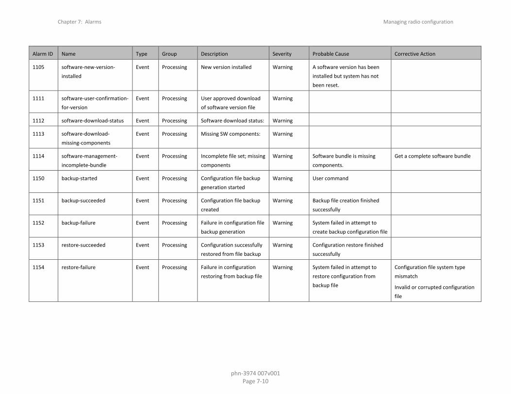
1105 software-new-version-installed
Event Processing New version installed Warning A software version has been installed but system has not been reset.
1111 software-user-confirmation-for-version
Event Processing User approved download of software version file
Warning
1112 software-download-status Event Processing Software download status: Warning
1113 software-download-missing-components
Event Processing Missing SW components: Warning
1114 software-management-incomplete-bundle
Event Processing Incomplete file set; missing components
Warning Software bundle is missing components.
Get a complete software bundle
1150 backup-started Event Processing Configuration file backup generation started
Warning User command
1151 backup-succeeded Event Processing Configuration file backup created
Warning Backup file creation finished successfully
1152 backup-failure Event Processing Failure in configuration file backup generation
Warning System failed in attempt to create backup configuration file
1153 restore-succeeded Event Processing Configuration successfully restored from file backup
Warning Configuration restore finished successfully
1154 restore-failure Event Processing Failure in configuration restoring from backup file
Warning System failed in attempt to restore configuration from backup file
Configuration file system type mismatch
Invalid or corrupted configuration file

Chapter 7: Alarms Managing radio configuration
phn-3974 007v001 Page 7-11
Alarm ID Name Type Group Description Severity Probable Cause Corrective Action
1155 restore-canceled Event Processing Configuration restore operation cancelled
Warning Restore operation cancelled because of user command or execution of another configuration management operation
Try again
1156 file-transfer-issued Event Processing User issued command for transfer of configuration file
Warning User command
1157 file-transfer-succeeded Event Processing Configuration file transfer successful
Warning Configuration file transfer successful
1158 file-transfer-failure Event Processing Configuration file transfer failure
Warning Communications failure.
File not found in server
Mark sure protocol details are properly configured.
Make sure file exists.
1159 file-transfer-in-progress Event Processing Configuration file transfer in progress
Warning File transfer started
1163 cli-script-activation-started Event Processing CLI configuration script activation started
Warning User command
1164 cli-script-activation-succeeded
Event Processing CLI Configuration script executed successfully
Warning
1165 cli-script-activation-failure Event Processing CLI Configuration script failed
Warning Syntax Error.
Error returned by system during runtime
Verify script in the relevant line, and run again.
Note that script may assume pre-existing configuration.
1166 unit-info-file-transfer-status-changed
Event Processing Unit info file transfer status:
Warning

Chapter 7: Alarms Managing radio configuration
phn-3974 007v001 Page 7-12
Alarm ID Name Type Group Description Severity Probable Cause Corrective Action
1167 unit-info-file-creation-status-changed
Event Processing Unit info file creation status:
Warning
1169 restore-started Event Processing Configuration restore operation started
Warning Restore operation started because of user command
1201 file-missed Alarm Equipment Modem firmware file not found
Critical Modem file is missing Download software package.
Reset the system.
1202 load-failed Alarm Equipment Modem firmware was not loaded successfully
Critical Modem firmware file is corrupted.
System failure.
Download software package.
Reset the system.
1203 modem-wd-reset Event Equipment Modem watch-dog reset event
Warning
1301 fpga-file-currupt-alarm Alarm Equipment Radio MRMC script LUT file is corrupted
Critical Damaged radio MRMC script LUT file
Download the specific radio MRMC script LUT file
1302 fpga-file-not-found-alarm Alarm Equipment Radio MRMC script LUT file is not found
Critical Missing radio MRMC script LUT file
Download the specific radio MRMC script LUT file
1304 modem-script-file-corrupt-alarm
Alarm Equipment Radio MRMC script modem file is corrupted
Critical Damaged radio MRMC script modem file
Download the specific radio MRMC script modem file
1305 modem-script-file-not-found-alarm
Alarm Equipment Radio MRMC script modem file is not found
Critical Missing radio MRMC script modem file
Download the specific radio MRMC script modem file
1308 rfu-file-corrupt-alarm Alarm Equipment Radio MRMC file is corrupted
Critical Damaged Radio MRMC script LUT file
Download the specific radio MRMC RFU file
1309 rfu-file-not-found-alarm Alarm Equipment Radio MRMC RFU file is not found
Major Missing radio MRMC RFU file Download the specific radio MRMC RFU file
1312 script-loading-failed Alarm Equipment Radio errrror!
MRMC script loading failed
Major Damaged hardware module Replace the radio hardware module

Chapter 7: Alarms Managing radio configuration
phn-3974 007v001 Page 7-13
Alarm ID Name Type Group Description Severity Probable Cause Corrective Action
1401 incompatible-rfu-tx-calibration
Alarm Equipment Incompatible RFU TX calibration
Major RFU calibration tables require SW upgrade
Upgrade IDU SW
1501 remote-communication-failure
Alarm Equipment Remote communication failure
Critical Fade in the link Check the link performance
1601 if-loopback Alarm Equipment IF loopback Warning User enabled IF loopback Disable IF loopback
1602 lock-detect Alarm Equipment IF synthesizer is unlocked. Critical Extreme temperature condition.
HW failure.
Check installation.
Reset the RMC (Radio Modem Card) module.
Replace the RMC (Radio Modem Card).
1610 rsl-degradation-threshold-out-of-range
Alarm Equipment Radio Receive Signal Level is below the configured threshold
Warning RSL is very low due to:
Weather conditions, obstruction in antenna line of sight, antennae alignment.
Configured threshold needs to be adjusted.2.
Check for obstruction in link path.
Check the antennae alignment and link planning.
Recalculate the Path Loss and set the threshold accordingly.
Check link settings - Tx Power and Tx Frequency.
Check for a hardware problem.
1651 atpc-override Alarm Communications
ATPC overridden: Tx level has been equal to the Max Tx level for a longer time than allowed
Warning Actual transmitted signal level has been at its maximum value for longer than allowed. This is probably caused by a configuration error or link planning error.
Correct the transmission levels. The alarm will be cleared only upon manual clearing.

Chapter 7: Alarms Managing radio configuration
phn-3974 007v001 Page 7-14
Alarm ID Name Type Group Description Severity Probable Cause Corrective Action
1697 radio-unit-extreme-temperature
Alarm Equipment Radio unit extreme temperature
Warning Installation conditions.
Defective RFU.
Correct the installation conditions.
Verify that the product is operating according to specifications.
Replace the RFU.
1698 radio-unit-low-voltage Alarm Equipment Radio unit input voltage is too low
Warning Power supply output is too low.
Power cable to RFU is defective.
Check/replace the power supply connected to the RFU.
Check/replace the power cable connected to the RFU.
1699 radio-unit-high-voltage Alarm Equipment Radio unit input voltage is too high
Warning Power Supply output too high. Check power supply.
1700 fw-download-failure Alarm Communications
Radio unit not aligned to IDU
Critical FW alignment interrupted, power disruption, ODU cable malfunction.
Damaged ODU.
Reinitiate the FW download by disabling and then enabling the corresponding RFU port.
Replace the ODU
1701 cable-open Alarm Equipment Cable open Major Cable is not connected to radio card or RFU.
Check cables and connectors.
Replace Radio card.
Replace RFU.
1702 cable-short Alarm Equipment Cable short Major Physical short at the IF cable Check cables and connectors.
Replace Radio card.
Replace RFU.
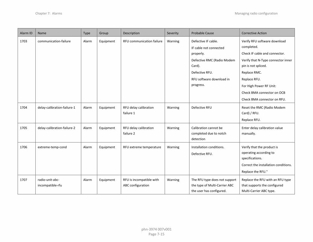
Chapter 7: Alarms Managing radio configuration
phn-3974 007v001 Page 7-15
Alarm ID Name Type Group Description Severity Probable Cause Corrective Action
1703 communication-failure Alarm Equipment RFU communication failure Warning Defective IF cable.
IF cable not connected properly.
Defective RMC (Radio Modem Card).
Defective RFU.
RFU software download in progress.
Verify RFU software download completed.
Check IF cable and connector.
Verify that N-Type connector inner pin is not spliced.
Replace RMC.
Replace RFU.
For High Power RF Unit:
Check BMA connector on OCB
Check BMA connector on RFU.
1704 delay-calibration-failure-1 Alarm Equipment RFU delay calibration failure 1
Warning Defective RFU Reset the RMC (Radio Modem Card) / RFU.
Replace RFU.
1705 delay-calibration-failure-2 Alarm Equipment RFU delay calibration failure 2
Warning Calibration cannot be completed due to notch detection
Enter delay calibration value manually.
1706 extreme-temp-cond Alarm Equipment RFU extreme temperature Warning Installation conditions.
Defective RFU.
Verify that the product is operating according to specifications.
Correct the installation conditions.
Replace the RFU."
1707 radio-unit-abc-incompatible-rfu
Alarm Equipment RFU is incompatible with ABC configuration
Warning The RFU type does not support the type of Multi-Carrier ABC the user has configured.
Replace the RFU with an RFU type that supports the configured Multi-Carrier ABC type.
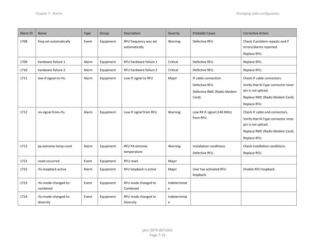
Chapter 7: Alarms Managing radio configuration
phn-3974 007v001 Page 7-16
Alarm ID Name Type Group Description Severity Probable Cause Corrective Action
1708 freq-set-automatically Event Equipment RFU frequency was set automatically
Warning Defective RFU Check if problem repeats and if errors/alarms reported.
Replace RFU.
1709 hardware-failure-1 Alarm Equipment RFU hardware failure 1 Critical Defective RFU. Replace RFU.
1710 hardware-failure-2 Alarm Equipment RFU hardware failure 2 Critical Defective RFU. Replace RFU.
1711 low-if-signal-to-rfu Alarm Equipment Low IF signal to RFU Major IF cable connection.
Defective RFU.
Defective RMC (Radio Modem Card).
Check IF cable connectors.
Verify that N-Type connector inner pin is not spliced.
Replace RMC (Radio Modem Card).
Replace RFU.
1712 no-signal-from-rfu Alarm Equipment Low IF signal from RFU Warning Low RX IF signal (140 MHz) from RFU.
Check IF cable and connectors.
Verify that N-Type connector inner pin is not spliced.
Replace RMC (Radio Modem Card).
Replace RFU.
1713 pa-extreme-temp-cond Alarm Equipment RFU PA extreme temperature
Warning Installation conditions.
Defective RFU.
Check installation conditions.
Replace RFU.
1721 reset-occurred Event Equipment RFU reset Major
1722 rfu-loopback-active Alarm Equipment RFU loopback is active Major User has activated RFU loopback.
Disable RFU loopback.
1723 rfu-mode-changed-to-combined
Event Equipment RFU mode changed to Combined
Indeterminate
1724 rfu-mode-changed-to-diversity
Event Equipment RFU mode changed to Diversity
Indeterminate

Chapter 7: Alarms Managing radio configuration
phn-3974 007v001 Page 7-17
Alarm ID Name Type Group Description Severity Probable Cause Corrective Action
1725 rfu-mode-changed-to-main Event Equipment RFU mode changed to Main
Indeterminate
1726 rfu-power-supply-failure Alarm Equipment RFU power supply failure Major At least one of the RFU's power supply voltages is too low.
Check the RFU cable connection.
Replace the RFU.
1727 rx-level-out-of-range Alarm Equipment RFU RX level out of range Warning RSL is very low, link is down. Check antenna alignment & link planning.
Check link settings (TX power, TX frequency).
Check antenna connections.
Replace local/remote RFU.
1728 rx-level-path1-out-of-range Alarm Equipment RFU RX level path1 out of range
Warning Improper installation.
Fading event.
Defective RFU.
Check that the fault is not due to rain/multi-path fading or lack of LOS.
Check link settings (TX power, TX frequency).
Check antenna alignment.
Check antenna connections.
Replace local/remote RFU.
1729 rx-level-path2-out-of-range Alarm Equipment RFU RX level path2 out of range
Warning Improper installation.
Fading event.
Defective RFU.
Check that the fault is not due to rain/multi-path fading or lack of LOS.
Check link settings (TX power, TX frequency).
Check antenna alignment.
Check antenna connections.
Replace local/remote RFU.
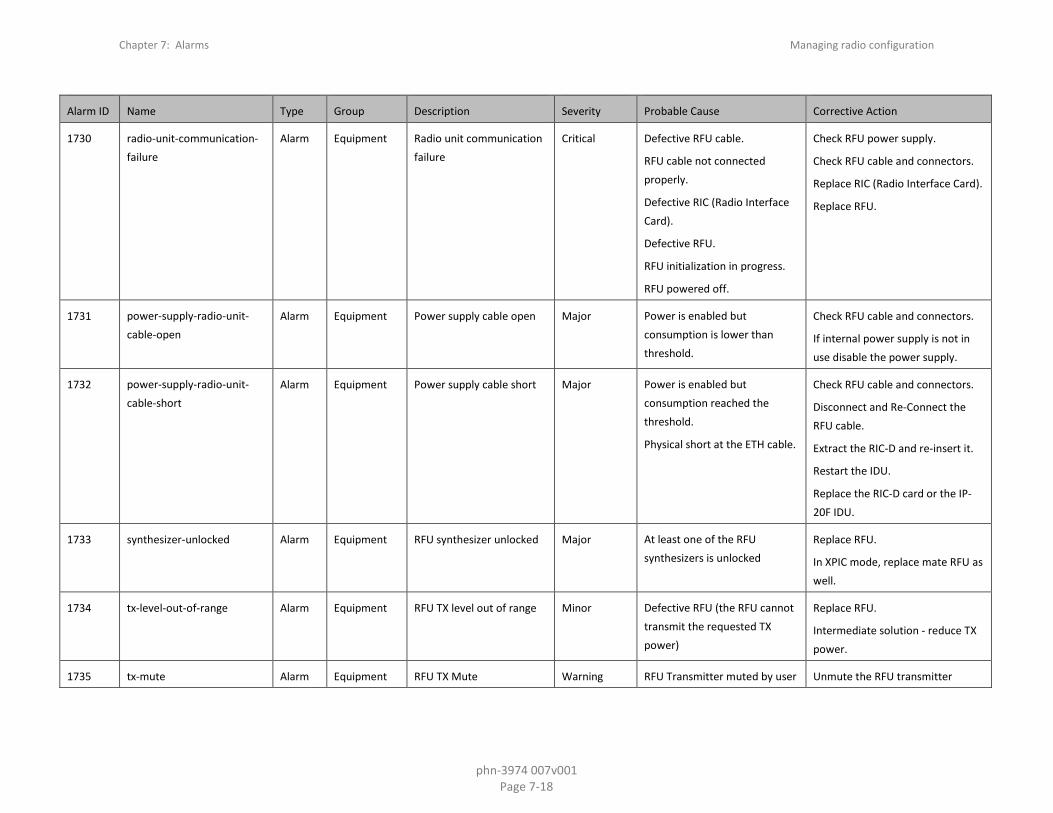
Chapter 7: Alarms Managing radio configuration
phn-3974 007v001 Page 7-18
Alarm ID Name Type Group Description Severity Probable Cause Corrective Action
1730 radio-unit-communication-failure
Alarm Equipment Radio unit communication failure
Critical Defective RFU cable.
RFU cable not connected properly.
Defective RIC (Radio Interface Card).
Defective RFU.
RFU initialization in progress.
RFU powered off.
Check RFU power supply.
Check RFU cable and connectors.
Replace RIC (Radio Interface Card).
Replace RFU.
1731 power-supply-radio-unit-cable-open
Alarm Equipment Power supply cable open Major Power is enabled but consumption is lower than threshold.
Check RFU cable and connectors.
If internal power supply is not in use disable the power supply.
1732 power-supply-radio-unit-cable-short
Alarm Equipment Power supply cable short Major Power is enabled but consumption reached the threshold.
Physical short at the ETH cable.
Check RFU cable and connectors.
Disconnect and Re-Connect the RFU cable.
Extract the RIC-D and re-insert it.
Restart the IDU.
Replace the RIC-D card or the IP-20F IDU.
1733 synthesizer-unlocked Alarm Equipment RFU synthesizer unlocked Major At least one of the RFU synthesizers is unlocked
Replace RFU.
In XPIC mode, replace mate RFU as well.
1734 tx-level-out-of-range Alarm Equipment RFU TX level out of range Minor Defective RFU (the RFU cannot transmit the requested TX power)
Replace RFU.
Intermediate solution - reduce TX power.
1735 tx-mute Alarm Equipment RFU TX Mute Warning RFU Transmitter muted by user Unmute the RFU transmitter

Chapter 7: Alarms Managing radio configuration
phn-3974 007v001 Page 7-19
Alarm ID Name Type Group Description Severity Probable Cause Corrective Action
1736 unknown-rfu-type Alarm Equipment IDU SW does not support this type of RFU
Major IDC SW does not support the RFU
Upgrade IDC SW
1737 card-extracted-from-slot Event Equipment Card was extracted from slot
Warning Card was extracted from slot NA
1738 card-failure Alarm Equipment Card is in Failure state Major Card is down as a result of card failure
Reset Card.
Check if slot was disabled.
1739 card-fpga-fw-not-found Alarm Equipment FPGA Firmware file not found
Critical There is no FPGA file found on the Main Board for the card on the slot
NA
1740 card-fw-load-fail Alarm Equipment Download card firmware has failed
Major Firmware download was unsuccessful.
Reset Card.
Download software package.
Try to insert another Card.
1741 card-inserted-to-slot Event Equipment Card was inserted to slot Warning Card was inserted to slot NA
1742 card-intermediate-channel-failure
Alarm Equipment Card is in interconnection failure state
Major Card is down as a result of card interconnection failure
Reset Card.
Check if the slot was disabled.
1743 card-missing Alarm Equipment Expected Card is missing in slot
Major Card is missing.
Expected Card Type configured on empty slot.
Insert Expected Card.
Clear Expected Card Type.
1744 card-not-supported-for-slot Alarm Equipment This Card type is not supported in this slot
Major The card is not on the Allowed Card Types list for this slot.
Reset.
Insert Card belongs to Allowed Card Types list.
1745 card-state-is-down Event Equipment Card operational state is Down
Indeterminate
Card state was change to Down state
NA
1746 card-state-is-up Event Equipment Card operational state is Up
Indeterminate
Card state was change to Up state
NA
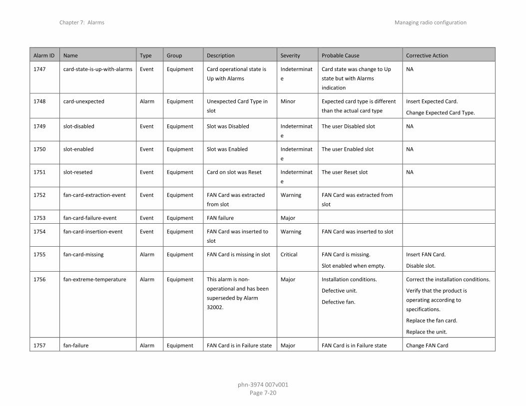
Chapter 7: Alarms Managing radio configuration
phn-3974 007v001 Page 7-20
Alarm ID Name Type Group Description Severity Probable Cause Corrective Action
1747 card-state-is-up-with-alarms Event Equipment Card operational state is Up with Alarms
Indeterminate
Card state was change to Up state but with Alarms indication
NA
1748 card-unexpected Alarm Equipment Unexpected Card Type in slot
Minor Expected card type is different than the actual card type
Insert Expected Card.
Change Expected Card Type.
1749 slot-disabled Event Equipment Slot was Disabled Indeterminate
The user Disabled slot NA
1750 slot-enabled Event Equipment Slot was Enabled Indeterminate
The user Enabled slot NA
1751 slot-reseted Event Equipment Card on slot was Reset Indeterminate
The user Reset slot NA
1752 fan-card-extraction-event Event Equipment FAN Card was extracted from slot
Warning FAN Card was extracted from slot
1753 fan-card-failure-event Event Equipment FAN failure Major
1754 fan-card-insertion-event Event Equipment FAN Card was inserted to slot
Warning FAN Card was inserted to slot
1755 fan-card-missing Alarm Equipment FAN Card is missing in slot Critical FAN Card is missing.
Slot enabled when empty.
Insert FAN Card.
Disable slot.
1756 fan-extreme-temperature Alarm Equipment This alarm is non-operational and has been superseded by Alarm 32002.
Major Installation conditions.
Defective unit.
Defective fan.
Correct the installation conditions.
Verify that the product is operating according to specifications.
Replace the fan card.
Replace the unit.
1757 fan-failure Alarm Equipment FAN Card is in Failure state Major FAN Card is in Failure state Change FAN Card
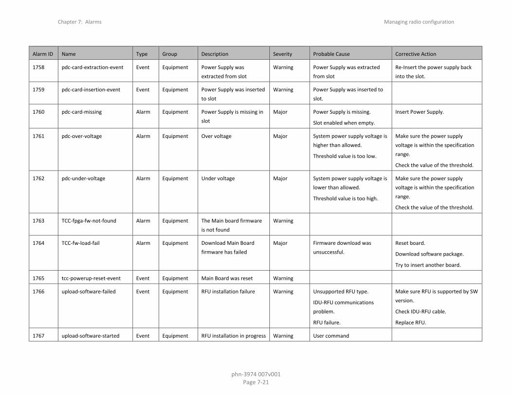
Chapter 7: Alarms Managing radio configuration
phn-3974 007v001 Page 7-21
Alarm ID Name Type Group Description Severity Probable Cause Corrective Action
1758 pdc-card-extraction-event Event Equipment Power Supply was extracted from slot
Warning Power Supply was extracted from slot
Re-Insert the power supply back into the slot.
1759 pdc-card-insertion-event Event Equipment Power Supply was inserted to slot
Warning Power Supply was inserted to slot.
1760 pdc-card-missing Alarm Equipment Power Supply is missing in slot
Major Power Supply is missing.
Slot enabled when empty.
Insert Power Supply.
1761 pdc-over-voltage Alarm Equipment Over voltage Major System power supply voltage is higher than allowed.
Threshold value is too low.
Make sure the power supply voltage is within the specification range.
Check the value of the threshold.
1762 pdc-under-voltage Alarm Equipment Under voltage Major System power supply voltage is lower than allowed.
Threshold value is too high.
Make sure the power supply voltage is within the specification range.
Check the value of the threshold.
1763 TCC-fpga-fw-not-found Alarm Equipment The Main board firmware is not found
Warning
1764 TCC-fw-load-fail Alarm Equipment Download Main Board firmware has failed
Major Firmware download was unsuccessful.
Reset board.
Download software package.
Try to insert another board.
1765 tcc-powerup-reset-event Event Equipment Main Board was reset Warning
1766 upload-software-failed Event Equipment RFU installation failure Warning Unsupported RFU type.
IDU-RFU communications problem.
RFU failure.
Make sure RFU is supported by SW version.
Check IDU-RFU cable.
Replace RFU.
1767 upload-software-started Event Equipment RFU installation in progress Warning User command
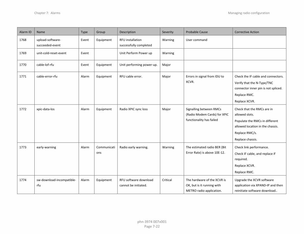
Chapter 7: Alarms Managing radio configuration
phn-3974 007v001 Page 7-22
Alarm ID Name Type Group Description Severity Probable Cause Corrective Action
1768 upload-software-succeeded-event
Event Equipment RFU installation successfully completed
Warning User command
1769 unit-cold-reset-event Event Unit Perform Power up Warning
1770 cable-lof-rfu Event Equipment Unit performing power-up. Major
1771 cable-error-rfu Alarm Equipment RFU cable error. Major Errors in signal from IDU to XCVR.
Check the IF cable and connectors.
Verify that the N-Type/TNC connector inner pin is not spliced.
Replace RMC.
Replace XCVR.
1772 xpic-data-los Alarm Equipment Radio XPIC sync loss Major Signalling between RMCs (Radio Modem Cards) for XPIC functionality has failed
Check that the RMCs are in allowed slots.
Populate the RMCs in different allowed location in the chassis.
Replace RMC/s.
Replace chassis.
1773 early-warning Alarm Communications
Radio early warning. Warning The estimated radio BER (Bit Error Rate) is above 10E-12.
Check link performance.
Check IF cable, and replace if required.
Replace XCVR.
Replace RMC.
1774 sw-download-incompatible-rfu
Alarm Equipment RFU software download cannot be initiated.
Critical The hardware of the XCVR is OK, but is it running with METRO radio application.
Upgrade the XCVR software application via XPAND-IP and then reinitiate software download..

Chapter 7: Alarms Managing radio configuration
phn-3974 007v001 Page 7-23
Alarm ID Name Type Group Description Severity Probable Cause Corrective Action
1775 hw-incompatible-rfu Alarm Equipment RFU software download is not possible.
Critical Wrong type of XCVR, the XCVR hardware is METRO.
Replace the XCVR
1776 pll-rmc Alarm Equipment RMC hardware failure. Major RMC hardware failure of the clock distributor.
Replace the RMC.
1777 rfu-mute-with-timeout Event Equipment RFU TX Mute with timeout Warning RFU Transmitter muted by user.
Unmute the RFU transmitter or wait for expiration of the timeout.
1778 rfu-power-decreased-due-to-pa-temp
Alarm Equipment RFU power decreased due to PA temperature
Major Defective RFU (the RFU cannot transmit the requested TX power).
Replace RFU.
Intermediate solution - reduce TX power.
1780 mrmc-running-script-deleted
Event Equipment MRMC running script is deleted
Warning New installed software package does not include the running MRMC radio script
Make sure the required software package include the running MRMC radio script.
Download and install the correct software package.
1781 mrmc-running-script-updated
Event Equipment MRMC running script is updated
Warning New installed software package does has an updated version of the running MRMC radio script
Reset the radio carrier to reacquire the new updated MRMC radio script
1782 radio-2_5gbps-mismatch-configuration
Alarm Equipment 2.5Gbps mismatch configuration
Warning The card can not function outside of an ABC group in 2.5Gbps mode.
Add the card to an ABC group, or change the Slot Section to 1Gbps.
1783 remote-fault-indication Alarm Communication
Radio remote fault indication (RFI)
Minor
1790 np-hw-failure Alarm Equipment Hardware failure Critical An internal hardware failure has been detected by the system.
Replace the card or unit which reports hardware failure.

Chapter 7: Alarms Managing radio configuration
phn-3974 007v001 Page 7-24
Alarm ID Name Type Group Description Severity Probable Cause Corrective Action
1794 interface-not-functional-until-reset
Alarm equipment Interface is not operational until chassis reset
Warning Changes were made to platform due to user configuration
Reset chassis
1800 t3-loc-alarm Alarm Equipment T3 sync interface Loss of Carrier
Major Cable disconnected.
Defective cable.
Check the cable connection.
Disable the interface in the Interface Manager.
1975 radio-fan-failure Alarm Equipment RFU fan failure Major RFU fan is disconnected.
RFU fan HW failure.
RFU fan jammed.
Check fan cable connection to the RFU.
Check/replace the fan.
Clear/clean the fan.
2001 pwe3-pwc-s-card-reset Alarm Equipment TDM-LIC has rebooted and is not in service now
Major Recent TDM-LIC card reset;
System malfunction.
Wait for card to reboot.
Reset the TDM-LIC card.
Replace card.
2002 pwe3-pwc-s-config-mismatch
Alarm Equipment TDM-LIC configuration mismatch
Major System malfunction. Reset the TDM-LIC.
Reset the Device.
Remove the TDM Configuration and Re-Configure it again.
2003 pwe3-pwc-s-front-panel-clock-los
Alarm Equipment Loss of Signal (LOS) on TDM-LIC's front panel clock port
Major Cable is not properly connected.
Reconnect cable.
Check line cables.
Check external equipment.
Reset the TDM-LIC.
2004 pwe3-pwc-s-host-pw-lic-comm-disrupt
Alarm Equipment Communication with TDM-LIC is disrupted in Host-Card direction
Minor System malfunction Reset the TDM-LIC.
Replace card.

Chapter 7: Alarms Managing radio configuration
phn-3974 007v001 Page 7-25
Alarm ID Name Type Group Description Severity Probable Cause Corrective Action
2005 pwe3-pwc-s-hw-failure Alarm Equipment TDM-LIC hardware failure Major System malfunction Reset the TDM-LIC.
Replace card.
2006 pwe3-pwc-s-pw-lic-host-comm-disrupt
Alarm Equipment No communication with TDM-LIC
Major TDM-LIC to Host communication failure.
Reset the TDM-LIC.
Reset the whole device.
Replace card.
2007 pwe3-pws-s-jitter-buffer-overrun
Alarm Equipment Jitter-buffer-overrun alarm on TDM service
Major TDM service synchronization failure.
Check TDM service configuration across the network.
Check the loop timing/clock recovery configuration.
2008 pwe3-pws-s-late-frame Alarm Equipment Late-frame alarm on TDM service
Warning TDM service failure or device synchronization problem.
Check TDM service configuration across the network.
2009 pwe3-pws-s-loss-of-frames Alarm Equipment Loss-of-frames alarm on TDM service
Major Failure along the network path of TDM service
Check network or configuration for errors in the network transport side of the service
2010 pwe3-pws-s-malformed-frames
Alarm Equipment Malformed-frames alarm on TDM service
Major Payload size does not correspond to the defined value.
Mismatch in PT value in RTP header (if used)
Check TDM service configuration
2011 pwe3-pws-s-misconnection Alarm Equipment Misconnection alarm on TDM service
Major Stray packets with wrong RTP configurations are received and dropped.
Check TDM service configuration
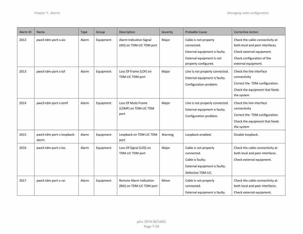
Chapter 7: Alarms Managing radio configuration
phn-3974 007v001 Page 7-26
Alarm ID Name Type Group Description Severity Probable Cause Corrective Action
2012 pwe3-tdm-port-s-ais Alarm Equipment Alarm Indication Signal (AIS) on TDM-LIC TDM port
Major Cable is not properly connected.
External equipment is faulty.
External equipment is not properly configured.
Check the cable connectivity at both local and peer interfaces.
Check external equipment.
Check configuration of the external equipment.
2013 pwe3-tdm-port-s-lof Alarm Equipment Loss Of Frame (LOF) on TDM-LIC TDM port
Major Line is not properly connected.
External equipment is faulty.
Configuration problem.
Check the line interface connectivity
Correct the TDM configuration.
Check the equipment that feeds the system
2014 pwe3-tdm-port-s-lomf Alarm Equipment Loss Of Multi-Frame (LOMF) on TDM-LIC TDM port
Major Line is not properly connected.
External equipment is faulty.
Configuration problem.
Check the line interface connectivity
Correct the TDM configuration.
Check the equipment that feeds the system
2015 pwe3-tdm-port-s-loopback-alarm
Alarm Equipment Loopback on TDM-LIC TDM port
Warning Loopback enabled. Disable loopback.
2016 pwe3-tdm-port-s-los Alarm Equipment Loss Of Signal (LOS) on TDM-LIC TDM port
Major Cable is not properly connected.
Cable is faulty;
External equipment is faulty;
Defective TDM-LIC.
Check the cable connectivity at both local and peer interfaces.
Check external equipment.
2017 pwe3-tdm-port-s-rai Alarm Equipment Remote Alarm Indication (RAI) on TDM-LIC TDM port
Minor Cable is not properly connected.
External equipment is faulty.
Check the cable connectivity at both local and peer interfaces.
Check external equipment.

Chapter 7: Alarms Managing radio configuration
phn-3974 007v001 Page 7-27
Alarm ID Name Type Group Description Severity Probable Cause Corrective Action
2018 pwe3-tdm-port-s-unexpected-signal-alarm
Alarm Equipment E1/DS1 Unexpected signal on TDM-LIC TDM port
Warning Line is connected to a disabled port.
Enable relevant port.
Disconnect cable from relevant port.
2021 pwe3-pwc-s-ssm-rx-changed
Event Equipment SSM received pattern change was discovered
Warning
No action is required.
2022 pwe3-stm1oc3-s-excessive-ber-alarm
Alarm Equipment Excessive BER on TDM-LIC STM1/OC3 port
Major Line is not properly connected.
External equipment is faulty.
Reconnect line.
Check line cables.
Check external equipment.
Power cycle the TDM-LIC.
2023 pwe3-stm1oc3-s-lof-alarm Alarm Equipment Loss Of Frame (LOF) on TDM-LIC STM1/OC3 port
Major Cable is not properly connected.
External equipment is faulty.
Wrong TDM configuration.
Check the cable connectivity at both local and peer interfaces.
Check external equipment.
Reset the TDM-LIC.
2024 pwe3-stm1oc3-s-loopback-alarm
Alarm Equipment Loopback on TDM-LIC STM1/OC3 port
Warning STM1/OC3 loopback enabled. Disable STM1/OC3 loopback.
2025 pwe3-stm1oc3-s-los-alarm Alarm Equipment Loss Of Signal (LOS) on TDM-LIC STM1/OC3 port
Critical Cable is not properly connected.
External equipment is faulty.
Peer Equipment Configuration problem.
Reconnect cable.
Check line cables.
Check external equipment.
Reset the TDM-LIC.
2026 pwe3-stm1oc3-s-mute-override-alarm
Alarm Equipment SFP is muted on TDM-LIC STM1/OC3 port
Warning The SFP interface has been muted.
Set the interface to mute OFF.
2027 pwe3-stm1oc3-s-sfp-absent-alarm
Alarm Equipment SFP absent in TDM-LIC STM1/OC3 port
Critical SFP is not inserted properly. Insert the SFP.

Chapter 7: Alarms Managing radio configuration
phn-3974 007v001 Page 7-28
Alarm ID Name Type Group Description Severity Probable Cause Corrective Action
2028 pwe3-stm1oc3-s-sfp-failure-alarm
Alarm Equipment SFP failure on TDM-LIC STM1/OC3 port
Critical SFP is not inserted properly.
Card is faulty.
Insert the SFP.
Replace the SFP.
Replace the card.
2029 pwe3-stm1oc3-s-sfp-tx-fail-alarm
Alarm Equipment SFP transmit failure on TDM-LIC STM1/OC3 port
Critical SFP is not inserted properly.
Card is faulty.
Insert the SFP.
Replace the SFP.
Replace the card.
2030 pwe3-stm1oc3-s-signal-degrade-alarm
Alarm Equipment Signal Degrade on TDM-LIC STM1/OC3 port
Minor Line is not properly connected.
SFP is not properly installed.
SFP is faulty.
External equipment is faulty
Install SFP properly.
Reconnect line.
Check line cables.
Check external equipment.
Change Signal Degrade Threshold.
2031 pwe3-stm1oc3-s-slm-alarm Alarm Equipment J0 Trace Identifier Mismatch on TDM-LIC STM1/OC3 port
Minor J0 misconfiguration.
Line is not properly connected.
SFP is not properly installed.
External equipment is faulty.
Make sure expected and received J0 identifiers match.
Connect line cables properly.
Install SFP properly.
2032 pwe3-stm1oc3-s-ssm-rx-changed
Event Equipment SSM pattern received on TDM-LIC STM1/OC3 port changed
Warning
2033 pwe3-vc12vt15-s-ais-alarm Alarm Equipment Alarm Indication Signal (AIS) on TDM-LIC VC12/VT1.5
Minor Cable is not properly connected.
Local/Peer Configuration is incorrect.
Check the cable connectivity at both local and peer interfaces.
Check/Correct the configuration at the local/peer.

Chapter 7: Alarms Managing radio configuration
phn-3974 007v001 Page 7-29
Alarm ID Name Type Group Description Severity Probable Cause Corrective Action
2034 pwe3-vc12vt15-s-excessive-ber-alarm
Alarm Equipment Excessive BER on TDM-LIC VC12/VT1.5
Minor Line is not properly connected.
External equipment is faulty.
Check the line cables.
Fix the problem at the peer.
Change the Excessive BER threshold.
2035 pwe3-vc12vt15-s-loopback-alarm
Alarm Equipment Loopback on TDM-LIC VC12/VT1.5
Warning Loopback enabled on TDM-LIC VC12/VC11.
Disable loopback on TDM-LIC VC12/VC11.
2036 pwe3-vc12vt15-s-rcv-plm-alarm
Alarm Equipment Payload Mismatch Path (PLM) received on TDM-LIC VC12/VT1.5
Minor Incorrect VC12/VC11 configuration
Check/Correct the configuration at the local/peer.
2037 pwe3-vc12vt15-s-rcv-rdi-alarm
Alarm Equipment Remote Defect Indication (RDI) received on TDM-LIC VC12/VT1.5
Minor Alarm exists along the Trail.
Cable is not properly connected.
Fix the problem along the trail.
Check the cable connectivity at both local and peer interfaces.
2038 pwe3-vc12vt15-s-rcv-slm-alarm
Alarm Equipment Signal Label Mismatch (SLM) received on TDM-LIC VC12/VT1.5
Minor J2 misconfiguration.
Line is not properly connected.
External equipment is faulty.
Make sure expected and receive J2 match
Reconnect line.
Check line cables.
Check external equipment.
Reset the TDM-LIC.
2039 pwe3-vc12vt15-s-signal-degrade-alarm
Alarm Equipment Signal Degrade on TDM-LIC VC12/VT1.5
Minor Line is not properly connected.
External equipment is faulty.
Reconnect line.
Check line cables.
Check external equipment.
Reset the TDM-LIC.
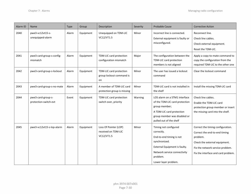
Chapter 7: Alarms Managing radio configuration
phn-3974 007v001 Page 7-30
Alarm ID Name Type Group Description Severity Probable Cause Corrective Action
2040 pwe3-vc12vt15-s-unequipped-alarm
Alarm Equipment Unequipped on TDM-LIC VC12/VT1.5
Minor Incorrect line is connected.
External equipment is faulty or misconfigured.
Reconnect line.
Check line cables.
Check external equipment.
Reset the TDM-LIC.
2041 pwe3-card-group-s-config-mismatch
Alarm Equipment TDM-LIC card protection configuration mismatch
Major The configuration between the TDM-LIC card protection members is not aligned
Apply a copy-to-mate command to copy the configuration from the required TDM-LIC to the other one
2042 pwe3-card-group-s-lockout Alarm Equipment TDM-LIC card protection group lockout command is on
Minor The user has issued a lockout command
Clear the lockout command
2043 pwe3-card-group-s-no-mate Alarm Equipment A member of TDM-LIC card protection group is missing
Minor TDM-LIC card is not installed in the shelf
Install the missing TDM-LIC card
2044 pwe3-card-group-s-protection-switch-evt
Event Equipment TDM-LIC card protection switch over, priority
Warning LOS alarm on a STM1 interface of the TDM-LIC card protection group member;
A TDM-LIC card protection group member was disabled or pulled out of the shelf
Check line cables.
Enable the TDM-LIC card protection group member or insert the missing card into the shelf.
2045 pwe3-vc12vt15-s-lop-alarm Alarm Equipment Loss Of Pointer (LOP) received on TDM-LIC VC12/VT1.5
Minor Timing not configured correctly.
End-to-end timing is not synchronized.
External Equipment is faulty.
Network service connectivity problem.
Lower layer problem.
Correct the timing configuration.
Correct the end-to-end timing problem.
Check the external equipment.
Fix the network service problem.
Fix the interface and card problem.

Chapter 7: Alarms Managing radio configuration
phn-3974 007v001 Page 7-31
Alarm ID Name Type Group Description Severity Probable Cause Corrective Action
2046 pwe3-tunnel-groups-s-protection-switch
Event Equipment Path protection switch on TDM service
Minor Failure along service primary path.
User command.
Check errors along primary path
Check local service configuration.
2047 pwe3-tunnel-groups-s-revertive-switch
Event Equipment Path protection revertive switch on TDM service
Minor Primary path has been operational for the duration of the defined WTR time
-
2100 STM-1-OC-3-IN-LOS Alarm Equipment Loss of Signal on Line Interface (LOS) on STM-1/OC-3 port.
Critical Line is not properly connected.
External equipment is faulty.
Reconnect line.
Check line cables.
Check external equipment.
2101 STM-1-OC-3-IN-LOF Alarm Equipment Loss of Frame on Line Interface (LOF) on STM-1/OC-3 port.
Major Line is not properly connected.
External equipment is faulty.
Reconnect line.
Check line cables.
Check external equipment.
2102 STM-1-OC-3-IN-MSAIS Alarm Equipment Alarm Indication Signal on Line Interface (MS-AIS/AIS-L) received.
Minor Line is not properly connected.
External equipment is faulty.
Reconnect line.
Check line cables.
Check external equipment.
2103 STM-1-OC-3-IN-MSRDI Alarm Equipment Remote Defect Indication on Line Interface (MS-RDI/RDI-L) received.
Minor External equipment is faulty. Reconnect line.
Check line cables.
Check external equipment.
2104 STM-1-OC-3-RX-LOS Alarm Equipment Loss of STM-1/OC-3 Frame on Radio Interface.
Major All channels in Multi Carrier ABC group are down.
Incorrect configuration on remote side.
Check link performance.
Check radio alarms for channel.
Check configuration.
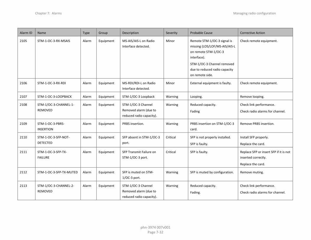
Chapter 7: Alarms Managing radio configuration
phn-3974 007v001 Page 7-32
Alarm ID Name Type Group Description Severity Probable Cause Corrective Action
2105 STM-1-OC-3-RX-MSAIS Alarm Equipment MS-AIS/AIS-L on Radio Interface detected.
Minor Remote STM-1/OC-3 signal is missing (LOS/LOF/MS-AIS/AIS-L on remote STM-1/OC-3 interface).
STM-1/OC-3 Channel removed due to reduced radio capacity on remote side.
Check remote equipment.
2106 STM-1-OC-3-RX-RDI Alarm Equipment MS-RDI/RDI-L on Radio Interface detected.
Minor External equipment is faulty. Check remote equipment.
2107 STM-1-OC-3-LOOPBACK Alarm Equipment STM-1/OC-3 Loopback Warning Looping. Remove looping.
2108 STM-1/OC-3-CHANNEL-1-REMOVED
Alarm Equipment STM-1/OC-3 Channel Removed alarm (due to reduced radio capacity).
Warning Reduced capacity.
Fading
Check link performance.
Check radio alarms for channel.
2109 STM-1-OC-3-PBRS-INSERTION
Alarm Equipment PRBS insertion. Warning PRBS insertion on STM-1/OC-3 card.
Remove PRBS insertion.
2110 STM-1-OC-3-SFP-NOT-DETECTED
Alarm Equipment SFP absent in STM-1/OC-3 port.
Critical SFP is not properly installed.
SFP is faulty.
Install SFP properly.
Replace the card.
2111 STM-1-OC-3-SFP-TX-FAILURE
Alarm Equipment SFP Transmit Failure on STM-1/OC-3 port.
Critical SFP is faulty. Replace SFP or insert SFP if it is not inserted correctly.
Replace the card.
2112 STM-1-OC-3-SFP-TX-MUTED Alarm Equipment SFP is muted on STM-1/OC-3 port.
Warning SFP is muted by configuration. Remove muting.
2113 STM-1/OC-3-CHANNEL-2-REMOVED
Alarm Equipment STM-1/OC-3 Channel Removed alarm (due to reduced radio capacity).
Warning Reduced capacity.
Fading.
Check link performance.
Check radio alarms for channel.

Chapter 7: Alarms Managing radio configuration
phn-3974 007v001 Page 7-33
Alarm ID Name Type Group Description Severity Probable Cause Corrective Action
2114 STM-1/OC-3-CHANNEL-3-REMOVED
Alarm Equipment STM-1/OC-3 Channel Removed alarm (due to reduced radio capacity).
Warning Reduced capacity.
Fading.
Check link performance.
Check radio alarms for channel.
2115 STM-1/OC-3-CHANNEL-4-REMOVED
Alarm Equipment STM-1/OC-3 Channel Removed alarm (due to reduced radio capacity).
Warning Reduced capacity.
Fading.
Check link performance.
Check radio alarms for channel.
2116 STM-1/OC-3-CHANNEL-5-REMOVED
Alarm Equipment STM-1/OC-3 Channel Removed alarm (due to reduced radio capacity).
Warning Reduced capacity.
Fading.
Check link performance.
Check radio alarms for channel.
2117 STM-1/OC-3-CHANNEL-6-REMOVED
Alarm Equipment STM-1/OC-3 Channel Removed alarm (due to reduced radio capacity).
Warning Reduced capacity.
Fading.
Check link performance.
Check radio alarms for channel.
2118 STM-1/OC-3-CHANNEL-7-REMOVED
Alarm Equipment STM-1/OC-3 Channel Removed alarm (due to reduced radio capacity).
Warning Reduced capacity.
Fading.
Check link performance.
Check radio alarms for channel.
2119 STM-1/OC-3-CHANNEL-8-REMOVED
Alarm Equipment STM-1/OC-3 Channel Removed alarm (due to reduced radio capacity).
Warning Reduced capacity.
Fading.
Check link performance.
Check radio alarms for channel.
2120 STM1-OC3-GROUP-ACTIVITY-CHANGED
Event Equipment STM-1/OC-3 Group protection switchover
Warning LOS alarm on an STM-1/OC-3 interface.
STM1-OC3 Group protection group member was disabled or pulled out of the shelf.
Check line cables.
Check external equipment.

Chapter 7: Alarms Managing radio configuration
phn-3974 007v001 Page 7-34
Alarm ID Name Type Group Description Severity Probable Cause Corrective Action
2200 MC-ABC-Local-LOF Alarm Communications
Multi Carrier ABC LOF. Critical All channels in Multi Carrier ABC group are down.
Check link performance on all radio channels in Multi Carrier ABC group.
Check radio alarms for channels in Multi Carrier ABC group.
Check configuration of Multi Carrier ABC group.
2201 MC-ABC-local-cap-below Alarm Multi Carrier ABC bandwidth is below the threshold
Major One of the radio channels in the Multi Carrier ABC group has a lower capacity than expected
Minimum bandwidth threshold configuration is wrong
Check link performance on all radio channels in Multi Carrier ABC group
Check radio alarms for channels in Multi Carrier ABC group
Check configuration of Multi Carrier ABC group Minimum bandwidth threshold
2203 MC-ABC-Lvds-Error-Sl2 Alarm Equipment LVDS RX Error Slot 2. Major Hardware failure between RMC and TCC cards.
Replace RMC.
Replace TCC.
Replace chassis.
2204 MC-ABC-Lvds-Error-Sl3 Alarm Equipment LVDS RX Error Slot 3. Major Hardware failure between RMC and TCC cards.
Replace RMC.
Replace TCC.
Replace chassis.
2205 MC-ABC-Lvds-Error-Sl4 Alarm Equipment LVDS RX Error Slot 4. Major Hardware failure between RMC and TCC cards.
Replace RMC.
Replace TCC.
Replace chassis.

Chapter 7: Alarms Managing radio configuration
phn-3974 007v001 Page 7-35
Alarm ID Name Type Group Description Severity Probable Cause Corrective Action
2206 MC-ABC-Lvds-Error-Sl5 Alarm Equipment LVDS RX Error Slot 5. Major Hardware failure between RMC and TCC cards.
Replace RMC.
Replace TCC.
Replace chassis.
2207 MC-ABC-Lvds-Error-Sl6 Alarm Equipment LVDS RX Error Slot 6. Major Hardware failure between RMC and TCC cards.
Replace RMC.
Replace TCC.
Replace chassis.
2208 MC-ABC-Lvds-Error-Sl7 Alarm Equipment LVDS RX Error Slot 7. Major Hardware failure between RMC and TCC cards.
Replace RMC.
Replace TCC.
Replace chassis.
2209 MC-ABC-Lvds-Error-Sl8 Alarm Equipment LVDS RX Error Slot 8. Major Hardware failure between RMC and TCC cards.
Replace RMC.
Replace TCC.
Replace chassis.
2210 MC-ABC-Lvds-Error-Sl9 Alarm Equipment LVDS RX Error Slot 9. Major Hardware failure between RMC and TCC cards.
Replace RMC.
Replace TCC.
Replace chassis.
2211 MC-ABC-Lvds-Error-Sl10 Alarm Equipment LVDS RX Error Slot 10. Major Hardware failure between RMC and TCC cards.
Replace RMC.
Replace TCC.
Replace chassis.
2212 MC-ABC-Lvds-Error-Sl12 Alarm Equipment LVDS RX Error Slot 12. Major Hardware failure between RMC and TCC cards.
Replace RMC.
Replace TCC.
Replace chassis.
2219 MC-ABC-Ch-Id-Mismatch-Ch1
Alarm Equipment Multi Carrier ABC Channel Id Mismatch Ch1.
Warning Configuration failure. Compare Channel ID configuration with remote side.
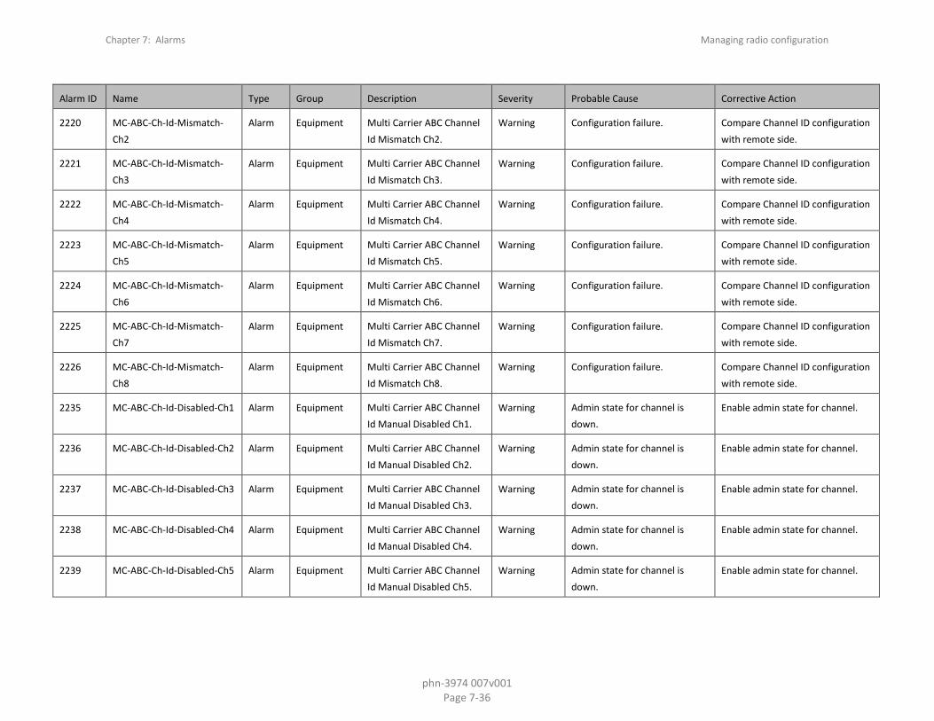
Chapter 7: Alarms Managing radio configuration
phn-3974 007v001 Page 7-36
Alarm ID Name Type Group Description Severity Probable Cause Corrective Action
2220 MC-ABC-Ch-Id-Mismatch-Ch2
Alarm Equipment Multi Carrier ABC Channel Id Mismatch Ch2.
Warning Configuration failure. Compare Channel ID configuration with remote side.
2221 MC-ABC-Ch-Id-Mismatch-Ch3
Alarm Equipment Multi Carrier ABC Channel Id Mismatch Ch3.
Warning Configuration failure. Compare Channel ID configuration with remote side.
2222 MC-ABC-Ch-Id-Mismatch-Ch4
Alarm Equipment Multi Carrier ABC Channel Id Mismatch Ch4.
Warning Configuration failure. Compare Channel ID configuration with remote side.
2223 MC-ABC-Ch-Id-Mismatch-Ch5
Alarm Equipment Multi Carrier ABC Channel Id Mismatch Ch5.
Warning Configuration failure. Compare Channel ID configuration with remote side.
2224 MC-ABC-Ch-Id-Mismatch-Ch6
Alarm Equipment Multi Carrier ABC Channel Id Mismatch Ch6.
Warning Configuration failure. Compare Channel ID configuration with remote side.
2225 MC-ABC-Ch-Id-Mismatch-Ch7
Alarm Equipment Multi Carrier ABC Channel Id Mismatch Ch7.
Warning Configuration failure. Compare Channel ID configuration with remote side.
2226 MC-ABC-Ch-Id-Mismatch-Ch8
Alarm Equipment Multi Carrier ABC Channel Id Mismatch Ch8.
Warning Configuration failure. Compare Channel ID configuration with remote side.
2235 MC-ABC-Ch-Id-Disabled-Ch1 Alarm Equipment Multi Carrier ABC Channel Id Manual Disabled Ch1.
Warning Admin state for channel is down.
Enable admin state for channel.
2236 MC-ABC-Ch-Id-Disabled-Ch2 Alarm Equipment Multi Carrier ABC Channel Id Manual Disabled Ch2.
Warning Admin state for channel is down.
Enable admin state for channel.
2237 MC-ABC-Ch-Id-Disabled-Ch3 Alarm Equipment Multi Carrier ABC Channel Id Manual Disabled Ch3.
Warning Admin state for channel is down.
Enable admin state for channel.
2238 MC-ABC-Ch-Id-Disabled-Ch4 Alarm Equipment Multi Carrier ABC Channel Id Manual Disabled Ch4.
Warning Admin state for channel is down.
Enable admin state for channel.
2239 MC-ABC-Ch-Id-Disabled-Ch5 Alarm Equipment Multi Carrier ABC Channel Id Manual Disabled Ch5.
Warning Admin state for channel is down.
Enable admin state for channel.
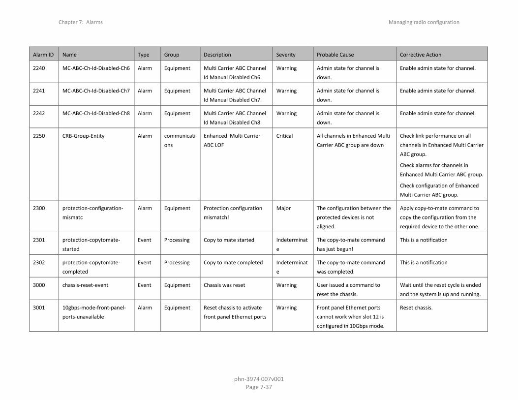
Chapter 7: Alarms Managing radio configuration
phn-3974 007v001 Page 7-37
Alarm ID Name Type Group Description Severity Probable Cause Corrective Action
2240 MC-ABC-Ch-Id-Disabled-Ch6 Alarm Equipment Multi Carrier ABC Channel Id Manual Disabled Ch6.
Warning Admin state for channel is down.
Enable admin state for channel.
2241 MC-ABC-Ch-Id-Disabled-Ch7 Alarm Equipment Multi Carrier ABC Channel Id Manual Disabled Ch7.
Warning Admin state for channel is down.
Enable admin state for channel.
2242 MC-ABC-Ch-Id-Disabled-Ch8 Alarm Equipment Multi Carrier ABC Channel Id Manual Disabled Ch8.
Warning Admin state for channel is down.
Enable admin state for channel.
2250 CRB-Group-Entity Alarm communications
Enhanced Multi Carrier ABC LOF
Critical All channels in Enhanced Multi Carrier ABC group are down
Check link performance on all channels in Enhanced Multi Carrier ABC group.
Check alarms for channels in Enhanced Multi Carrier ABC group.
Check configuration of Enhanced Multi Carrier ABC group.
2300 protection-configuration-mismatc
Alarm Equipment Protection configuration mismatch!
Major The configuration between the protected devices is not aligned.
Apply copy-to-mate command to copy the configuration from the required device to the other one.
2301 protection-copytomate-started
Event Processing Copy to mate started Indeterminate
The copy-to-mate command has just begun!
This is a notification
2302 protection-copytomate-completed
Event Processing Copy to mate completed Indeterminate
The copy-to-mate command was completed.
This is a notification
3000 chassis-reset-event Event Equipment Chassis was reset Warning User issued a command to reset the chassis.
Wait until the reset cycle is ended and the system is up and running.
3001 10gbps-mode-front-panel-ports-unavailable
Alarm Equipment Reset chassis to activate front panel Ethernet ports
Warning Front panel Ethernet ports cannot work when slot 12 is configured in 10Gbps mode.
Reset chassis.

Chapter 7: Alarms Managing radio configuration
phn-3974 007v001 Page 7-38
Alarm ID Name Type Group Description Severity Probable Cause Corrective Action
3002 slot-mode-front-panel-ports-not-functional
Alarm Equipment Front panel Ethernet port cannot function in current configured capacity mode
Warning Front panel Ethernet port cannot work in a mode other than 1Gbps.
Configure the relevant capacity mode to 1 Gbps mode.
3003 abc-mode-not-functional Alarm Equipment Multi Carrier ABC group is not functional in current configured capacity mode
Warning Multi Carrier ABC group does not support the configured capacity mode.
Configure the relevant capacity mode to 1 Gbps mode.
3004 abc-mode-not-functional-until-reset
Alarm Equipment Multi Carrier ABC group is not functional in current configured capacity mode until chassis is reset
Warning Multi Carrier ABC group capacity mode is different than the configured capacity mode.
Reset chassis.
4000 hw-failure Alarm Equipment Card has one or more HW failures
Critical One or more HW faults. Replace card.
4001 slotsection-2_5gbps-compatibility
Alarm Equipment Card can not function in 2.5Gbps mode.
Warning The user set an expected card that does not support 2.5Gbps.
Change the Slot Section to 1Gbps.
4002 slot-slotsection-10gbps-card-not-functional
Alarm Equipment Card is not functional until chassis is reset
Warning Slot is not in 10Gbps mode. Reset chassis.
5000 failure-login-event Event Equipment User blocked due to consecutive failure login
Indeterminate
User blocked due to consecutive failure login
The user should wait few minutes until it account will be unblock
5001 g8032-protection-switching-alarm
Alarm Processing ERPI is either in protection state or forced protection state
Minor Either user "force switch" command or one of the ring links has failed
Either clear force command or recover the link
5002 g8032-failure-of-protocol-pm-alarm
Alarm Processing More than a single RPL is configured in a ring
Warning RPL configuration is wrong. Reconfigure the RPL configuration.
5003 lldp-topology-change Event Processing LLDP topology change Warning New neighbor None
5004 security-log-upload-started-event
Event Equipment Security log upload started Indeterminate
Security log upload started

Chapter 7: Alarms Managing radio configuration
phn-3974 007v001 Page 7-39
Alarm ID Name Type Group Description Severity Probable Cause Corrective Action
5005 security-log-upload-failed-event
Event Equipment Security log upload failed Indeterminate
Security log upload failed
5006 security-log-upload-succeeded-event
Event Equipment Security log upload succeeded
Indeterminate
Security log upload succeeded
5010 force-mode-alarm Alarm Equipment System is in sync force mode state
Warning User command
5011 sync-quality-change-event Event Equipment The sync-source quality level was changed
Major
5012 system-clock-in-holdover-mode
Alarm Equipment System Synchronization Reference in Holdover Mode
Critical Active Sync Source Failure and the clock unit enters holdover mode
Fix the Sync Source Failure.
Provide an alternative sync source.
5013 sync-T0-quality-change-event
Event Equipment System sync reference T0 quality has changed
Major
5014 sync-pipe-invalid-interface-clock-source
Alarm Equipment The pipe interface clock-source in signal-interface table is not system-clock
Major For interfaces of a Pipe, the outgoing clock source type must be "System Clock".
Set the outgoing clock source type to System Clock in the Outgoing Clock Table via Outgoing Clock view in the Web EMS or the platform sync interface config command in the CLI.
5015 sync-pipe-missing-edge Alarm Equipment The pipe is missing an edge interface
Major Pipe Regenerator contains less than 2 interfaces.
Configure a second interface for the Pipe Regenerator.
5016 sync-pipe-interface-op-state-down
Alarm Equipment Pipe interface operational state is down
Major One or both of the Regenerator Interfaces status is down.
Check both interfaces of the pipe regenerator - admin and operational statuses.
Check Ethernet cable communication.
Make sure Radio Link is up.

Chapter 7: Alarms Managing radio configuration
phn-3974 007v001 Page 7-40
Alarm ID Name Type Group Description Severity Probable Cause Corrective Action
5017 sync-pipe-invalid-pipe Alarm Equipment Pipe is invalid Major Pipe Regenerator configuration is invalid or interface operational failure.
Fix the Pipe Regenerator configuration.
Ensure both interfaces are operational.
5018 sync-1588-tc-not-operational
Alarm Equipment 1588TC is not operational Major System Failure Reboot the unit
5019 sync-1588-tc-not-calibrated Alarm Sync 1588TC over the radio is not calibrated
Major 1588TC over the radio is enabled but could not be calibrated
Check that the radio link configuration have:
TC enabled on both sides
Frequency lock UP on both sides
TC downstream at one side and upstream on the other side
5020 sync-T3-remote-loopback Alarm Equipment T3 interface at loopback mode
Warning T3 Interface is configured in loopback.
If required, disable the loopback.
5021 sync-T4-analog-loopback Alarm Equipment T4 interface at loopback mode
Warning T4 Interface is configured in loopback.
If required, disable the loopback.
5030 soam-connectivity-failure Alarm Processing A connectivity failure in MA/MEG
Minor Wrong link configurations. Check the link in the traffic path
5031 soam-def-error-failure Alarm Processing Error CCM received Major Invalid CCMs has been received.
MEP Id does not exist or a wrong interval was received in the CCM.
Check the links along the traffic path.
Check the configuration of the MEPs.
5032 soam-def-mac-failure Alarm Processing Remote mep MAC status not up
Minor Remote MEP’s associated MAC is reporting an error status
Check remote Port Interface status

Chapter 7: Alarms Managing radio configuration
phn-3974 007v001 Page 7-41
Alarm ID Name Type Group Description Severity Probable Cause Corrective Action
5033 soam-def-rdi-failure Alarm Processing Mep Rdi received Minor Remote Defect indication has been received from remote MEP
Check the SOAM configurations.
Check that all local MEPs are configured correctly and enabled.
Check the service connectivity.
5034 soam-remote-ccm-failure Alarm Processing Remote mep CCMs are not received
Major The MEP is not receiving CCMs from at least one of the remote MEPs
Check all the remote SOAM configurations.
Check that all remote MEPs are configured correctly and enabled.
Check the service connectivity.
5035 soam-def-xcon-failure Alarm Processing Cross Connect CCM received
Major CCM from another MAID or lower MEG level have been received
Check MA/MEG and MEP configurations
5036 ptp-stream-state-change Event Processing 1588-BC port state changed
Warning
5037 ptp-bmca-update Event Processing 1588-BC BMCA has been updated.
Warning
5038 ptp-output-squelch Event Processing 1588-BC outputs are squelched.
Warning
5039 ptp-parent-data-set-change Event Processing 1588-BC parent dataset has changed.
Warning
5040 ptp-utc-offset-change Event Processing 1588-BC UTC offset value changed.
Warning
5041 ptp-leap-seconds-flag-change
Event Processing 1588-BC one of the leap seconds flags have changed.
Warning
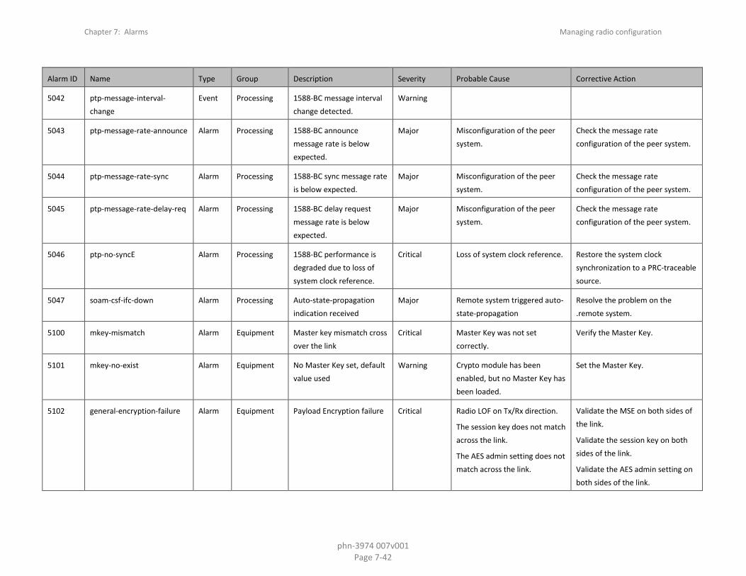
Chapter 7: Alarms Managing radio configuration
phn-3974 007v001 Page 7-42
Alarm ID Name Type Group Description Severity Probable Cause Corrective Action
5042 ptp-message-interval-change
Event Processing 1588-BC message interval change detected.
Warning
5043 ptp-message-rate-announce Alarm Processing 1588-BC announce message rate is below expected.
Major Misconfiguration of the peer system.
Check the message rate configuration of the peer system.
5044 ptp-message-rate-sync Alarm Processing 1588-BC sync message rate is below expected.
Major Misconfiguration of the peer system.
Check the message rate configuration of the peer system.
5045 ptp-message-rate-delay-req Alarm Processing 1588-BC delay request message rate is below expected.
Major Misconfiguration of the peer system.
Check the message rate configuration of the peer system.
5046 ptp-no-syncE Alarm Processing 1588-BC performance is degraded due to loss of system clock reference.
Critical Loss of system clock reference. Restore the system clock synchronization to a PRC-traceable source.
5047 soam-csf-ifc-down Alarm Processing Auto-state-propagation indication received
Major Remote system triggered auto-state-propagation
Resolve the problem on the .remote system.
5100 mkey-mismatch Alarm Equipment Master key mismatch cross over the link
Critical Master Key was not set correctly.
Verify the Master Key.
5101 mkey-no-exist Alarm Equipment No Master Key set, default value used
Warning Crypto module has been enabled, but no Master Key has been loaded.
Set the Master Key.
5102 general-encryption-failure Alarm Equipment Payload Encryption failure Critical Radio LOF on Tx/Rx direction.
The session key does not match across the link.
The AES admin setting does not match across the link.
Validate the MSE on both sides of the link.
Validate the session key on both sides of the link.
Validate the AES admin setting on both sides of the link.
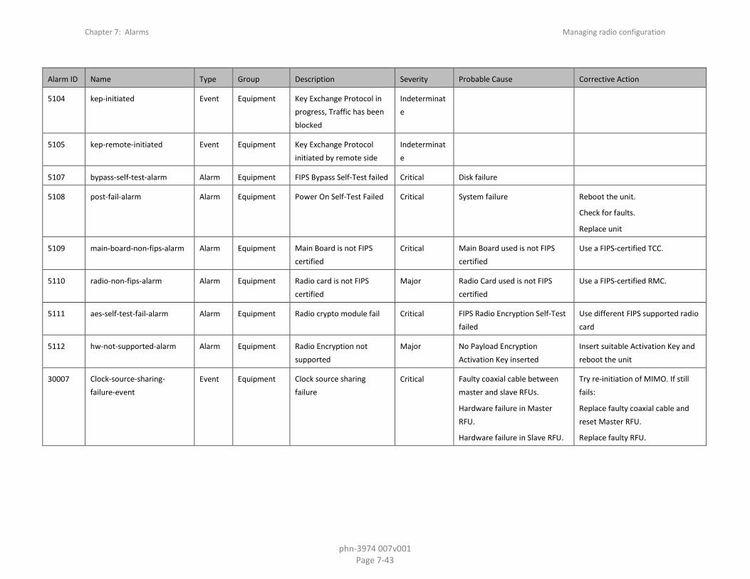
Chapter 7: Alarms Managing radio configuration
phn-3974 007v001 Page 7-43
Alarm ID Name Type Group Description Severity Probable Cause Corrective Action
5104 kep-initiated Event Equipment Key Exchange Protocol in progress, Traffic has been blocked
Indeterminate
5105 kep-remote-initiated Event Equipment Key Exchange Protocol initiated by remote side
Indeterminate
5107 bypass-self-test-alarm Alarm Equipment FIPS Bypass Self-Test failed Critical Disk failure
5108 post-fail-alarm Alarm Equipment Power On Self-Test Failed Critical System failure Reboot the unit.
Check for faults.
Replace unit
5109 main-board-non-fips-alarm Alarm Equipment Main Board is not FIPS certified
Critical Main Board used is not FIPS certified
Use a FIPS-certified TCC.
5110 radio-non-fips-alarm Alarm Equipment Radio card is not FIPS certified
Major Radio Card used is not FIPS certified
Use a FIPS-certified RMC.
5111 aes-self-test-fail-alarm Alarm Equipment Radio crypto module fail Critical FIPS Radio Encryption Self-Test failed
Use different FIPS supported radio card
5112 hw-not-supported-alarm Alarm Equipment Radio Encryption not supported
Major No Payload Encryption Activation Key inserted
Insert suitable Activation Key and reboot the unit
30007 Clock-source-sharing-failure-event
Event Equipment Clock source sharing failure
Critical Faulty coaxial cable between master and slave RFUs.
Hardware failure in Master RFU.
Hardware failure in Slave RFU.
Try re-initiation of MIMO. If still fails:
Replace faulty coaxial cable and reset Master RFU.
Replace faulty RFU.

Chapter 7: Alarms Managing radio configuration
phn-3974 007v001 Page 7-44
Alarm ID Name Type Group Description Severity Probable Cause Corrective Action
31000 Insufficient-conditions-for-MIMO-alarm
Alarm Equipment Insufficient conditions for MIMO
Critical Insufficient conditions for MIMO.
Hardware failure.
Make sure all cables between master and slave are connected (MIMO 4x4 only).
Replace faulty units and check that cables are plugged.
31003 Unsuitable-hardware-for-MIMO-alarm
Alarm Communications
Unsuitable hardware for MIMO
Critical Unsuitable hardware for MIMO operation requirements.
Dual carrier RFUs (MIMO 2x2 and 4x4).
RFUs with MIMO bus interface (MIMO 4x4).
Clock source sharing capability (MIMO 4x4).
Make sure both RFUs are compatible for MIMO operation.
31004 Unsuitable-software-configuration-for-MIMO-alarm
Alarm Communications
Unsuitable software configuration for MIMO
Critical Not all MIMO carriers are set to same radio script or script is not compatible for MIMO.
Radio TX and RX frequency is not identical on all MIMO carriers.
XPIC or Multi radio or ATPC features are enabled.
Load same MIMO compatible radio script to all MIMO carriers.
Set same TX and RX frequency on all MIMO carriers.
Disable XPIC, Multi radio and ATPC on all MIMO carriers.
31005 Clock-source-sharing-failure-alarm
Alarm Equipment Clock source sharing cable unplugged
Critical Faulty coaxial cable between master and slave RFUs
Mate does not exist
Replace faulty coaxial cable and reset Master RFU.
Replace faulty RFU.

Chapter 7: Alarms Managing radio configuration
phn-3974 007v001 Page 7-45
Alarm ID Name Type Group Description Severity Probable Cause Corrective Action
31100 AMCC-Incompatible-radio-script-alarm
Alarm Communications
Radio script is incompatible to AMCC
Critical MRMC Script selected does not support AMCC Group type/subtype
Set AFR Script in both Agg1 & Agg2 carriers
31101 AMCC-Inconsistent-MRMC-Script-alarm
Alarm Communications
Inconsistent MRMC script between members
Critical All members of a group must be configured to the same MRMC Script
Set the members to the appropriate MRMC script
31102 AMCC-Inconsistent-radio-frequency-alarm
Alarm Communications
Inconsistent radio frequency
Critical Radio TX/RX frequency is not identical on all AMCC carriers
Set same radio TX/RX frequency on all AMCC carriers
31103 AMCC-Failed-To-Load-Alarm Alarm Communications
Agg 1 failed Bring-up procedure
Critical Agg1 did not complete Bring-up successfully
Drop both Agg1 & Agg2 into single carrier mode (Pre-Init)
31104 AMCC-Invalid-ACM-Configuration-alarm
Alarm Communications
Invalid ACM configuration Critical AMCC member have been set to fixed profile
Set AMCC member to adaptive ACM profiles
31105 AMCC-Mimo-not-supported-alarm
Alarm Equipment AMCC/MIMO insufficient condition – configuration is not supported
Critical MIMO script is not enabled on any radio member.
Different TX/RX frequency.
ATPC enabled.
XPIC enabled.
ACM mode (adaptive/Fixed) is not the same.
Unit Redundancy enabled.
Platform not supported.
Align MIMO script on all radio members.
Align same frequency on all radio members.
Disable ATPC.
Disable XPIC.
Align ACM mode.
Disable Unit Redundancy.
Replace unit.
31106 AMCC-Master-failure-alarm Alarm Equipment AMCC insufficient condition – Master unit failure.
Critical Master unit failure. Verify Master unit power.
Replace hardware.

Chapter 7: Alarms Managing radio configuration
phn-3974 007v001 Page 7-46
Alarm ID Name Type Group Description Severity Probable Cause Corrective Action
31107 AMCC-Slave-failure-alarm Alarm Equipment AMCC insufficient condition – Slave unit failure.
Critical Slave unit failure. Verify Slave unit power.
Replace hardware.
31108 AMCC-Data-Sharing-cable-disconnected-alarm
Alarm Equipment AMCC insufficient condition – Data sharing cable failure.
Critical Data sharing cable failure. Verify Data sharing cable connected.
Replace Data sharing cable.
31109 AMCC-Prot-port-cable-disconnected-alarm
Alarm Equipment MIMO insufficient condition – Mate communication cable failure.
Critical Mate communication cable failure.
Verify Mate communication cable connected.
Replace Mate communication cable.
31110 AMCC-Source-Sharing-cable-disconnected-alarm
Alarm Equipment MIMO insufficient condition – Source sharing cable failure.
Critical Source sharing cable failure. Verify Source sharing cable connected.
Replace Source sharing cable.
31111 AMCC-Master-Slave-config-mismatch-alarm
Alarm Equipment MIMO insufficient condition - Master/Slave configuration mismatch
Critical Master/Slave configuration mismatch due to:
Different TX/RX frequency.
Different MIMO script ID.
Different ACM mode (adaptive/Fixed).
Align Master/Slave configuration.
31112 AMCC-Remote-failure-alarm Alarm Equipment AMCC insufficient condition – Remote failure
Critical AMCC remote failure. Handle AMCC remote failure.
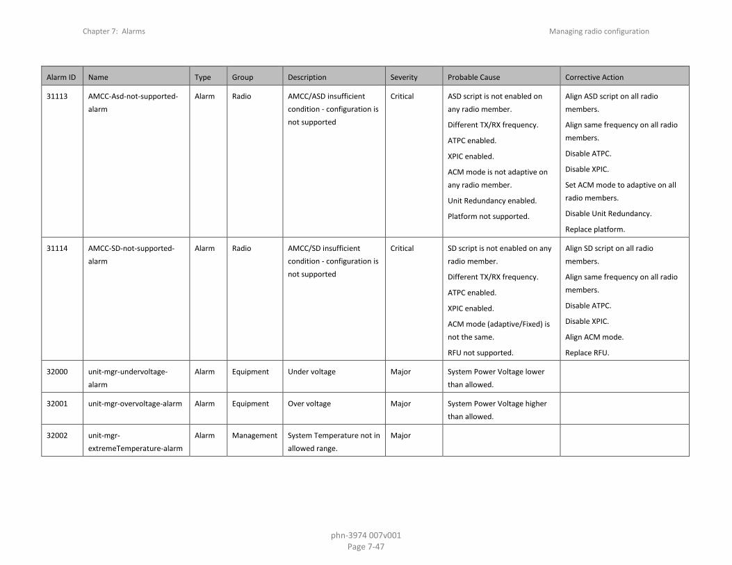
Chapter 7: Alarms Managing radio configuration
phn-3974 007v001 Page 7-47
Alarm ID Name Type Group Description Severity Probable Cause Corrective Action
31113 AMCC-Asd-not-supported-alarm
Alarm Radio AMCC/ASD insufficient condition - configuration is not supported
Critical ASD script is not enabled on any radio member.
Different TX/RX frequency.
ATPC enabled.
XPIC enabled.
ACM mode is not adaptive on any radio member.
Unit Redundancy enabled.
Platform not supported.
Align ASD script on all radio members.
Align same frequency on all radio members.
Disable ATPC.
Disable XPIC.
Set ACM mode to adaptive on all radio members.
Disable Unit Redundancy.
Replace platform.
31114 AMCC-SD-not-supported-alarm
Alarm Radio AMCC/SD insufficient condition - configuration is not supported
Critical SD script is not enabled on any radio member.
Different TX/RX frequency.
ATPC enabled.
XPIC enabled.
ACM mode (adaptive/Fixed) is not the same.
RFU not supported.
Align SD script on all radio members.
Align same frequency on all radio members.
Disable ATPC.
Disable XPIC.
Align ACM mode.
Replace RFU.
32000 unit-mgr-undervoltage-alarm
Alarm Equipment Under voltage Major System Power Voltage lower than allowed.
32001 unit-mgr-overvoltage-alarm Alarm Equipment Over voltage Major System Power Voltage higher than allowed.
32002 unit-mgr-extremeTemperature-alarm
Alarm Management System Temperature not in allowed range.
Major