Embed Size (px)
Citation preview
PTC-140
2
Table of Contents
TABLE OF CONTENTS ..................................................................................... 2
FCC COMPLIANCE STATEMENT ...................................................................... 5
WARNINGS AND PRECAUTIONS .................................................................... 5
WARRANTY ................................................................................................... 7
STANDARD WARRANTY .................................................................................... 7 THREE YEAR WARRANTY .................................................................................. 7
DISPOSAL ...................................................................................................... 8
1. PRODUCT OVERVIEW ................................................................................ 9
2. FEATURES .................................................................................................. 9
3. LOCATION AND FUNCTION OF PARTS ...................................................... 10
4. BASIC SETUP ............................................................................................ 13
4.1 POWER-ON INITIAL CONFIGURATION .......................................................... 13 4.2 VIDEO OUTPUT ...................................................................................... 13
NETWORK OUTPUT .......................................................................... 13
5. REMOTE CONTROL AND ON-SCREEN MENU ............................................ 15
5.1 REMOTE CONTROL FUNCTIONS .................................................................. 15 5.2 ON-SCREEN MENU (CONTROL BY REMOTE CONTROLLER) ................................. 19
6. INSTALLATION INSTRUCTIONS ................................................................. 26
7. DIRECT CONNECTION TO CAMERA........................................................... 30
7.1 RS-232 MINI-DIN 8 PIN DEFINITION .......................................................... 31 7.2 RS232 (DB9) PIN DEFINITION .................................................................. 31
8. PTC-140’S WEB-BASED USER INTERFACE ................................................. 32
8.1 HOW TO CONNECT THE PTC-140 CAMERA TO THE PC .................................... 32 8.1.1 Connect the Camera to the PC in DHCP Mode .............................. 32 8.1.2 How to Find the DHCP IP Address of the PTC-140 Camera ............ 35 8.1.3 Connect the Camera to the PC in Static IP Mode .......................... 38
8.2 INTRODUCTION OF THE PTC-140 WEB USER INTERFACE .................................. 40 8.2.1 Preview ....................................................................................... 40
3
8.2.1.1 The Operations of Zoom and Focus Buttons in Different Focus
Modes ................................................................................................. 43 8.2.1.2 How to Set the Preset Positon ................................................... 44 8.2.1.3 How to Recall the Pre-saved Preset ........................................... 44 8.2.1.4 How to Change the PTZ Speed of the Camera ........................... 44 8.2.2 Configuration .............................................................................. 44 8.2.2.1 Audio Configure ....................................................................... 45 8.2.2.2 Video Configure-Video Encode .................................................. 46 8.2.2.3 Video Configure-Stream Publish................................................ 50 8.2.2.3.1 How to Stream the PTC-140 Video to the RTMP Platform ....... 51 (Take Youtube as an Example) ............................................................. 51 8.2.2.3.2 How to Stream the PTC-140 Video to the RTMP Platform ....... 53 (Take Facebook as an Example) ........................................................... 53 8.2.2.4 RTP Multicast ........................................................................... 55 8.2.2.5 Video Parameters ..................................................................... 56 8.2.2.6 Video OSD ................................................................................ 62 How to Show Time and Title on the Screen ........................................... 62 How to Control the OSD Offset of Title and Time .................................. 62 8.2.2.7 OSD Font Size ........................................................................... 63 8.2.2.8 Video OUT ................................................................................ 63 8.2.2.9 Network Configure-Network Port ............................................. 64 8.2.2.10 Ethernet ................................................................................. 64 How to Set the Camera in DHCP Mode ................................................. 65 8.2.2.11 DNS ........................................................................................ 65 8.2.2.12 System Configure-System Attribute......................................... 65 How to Change the OSD Language ....................................................... 66 8.2.2.13 System Time ........................................................................... 66 8.2.2.14 System User ........................................................................... 67 How to Set the User Name and Password for System User .................... 67 8.2.2.15 Update ................................................................................... 67 How to Update the Latest Firmware for the PTC-140 Camera ............... 68 8.2.2.16 Default ................................................................................... 68 8.2.2.17 Reboot ................................................................................... 69 8.2.3 Logout ........................................................................................ 69
9. FIRMWARE UPDATE ................................................................................ 70
How to Update the Latest Firmware for the PTC-140 Camera ............... 70
4
10. FREQUENTLY-ASKED QUESTIONS ........................................................... 71
11. DIMENSIONS ......................................................................................... 74
12. SPECIFICATIONS ..................................................................................... 75
SERVICE & SUPPORT .................................................................................... 80
Disclaimer of Product and Services The information offered in this instruction manual is intended as a guide only. At all times, Datavideo Technologies will try to give correct, complete and suitable information. However, Datavideo Technologies cannot exclude that some information in this manual, from time to time, may not be correct or may be incomplete. This manual may contain typing errors, omissions or incorrect information. Datavideo Technologies always recommend that you double check the information in this document for accuracy before making any purchase decision or using the product. Datavideo Technologies is not responsible for any omissions or errors, or for any subsequent loss or damage caused by using the information contained within this manual. Further advice on the content of this manual or on the product can be obtained by contacting your local Datavideo Office or dealer.
5
FCC Compliance Statement This device complies with part 15 of the FCC rules. Operation is subject to the following two conditions: (1) This device may not cause harmful interference, and (2) This device must accept any interference received, including interference
that may cause undesired operation.
Warnings and Precautions 1. Read all of these warnings and save them for later reference. 2. Follow all warnings and instructions marked on this unit. 3. Unplug this unit from the wall outlet before cleaning. Do not use liquid or
aerosol cleaners. Use a damp cloth for cleaning. 4. Do not use this unit in or near water. 5. Do not place this unit on an unstable cart, stand, or table. The unit may
fall, causing serious damage. 6. Slots and openings on the cabinet top, back, and bottom are provided for
ventilation. To ensure safe and reliable operation of this unit, and to protect it from overheating, do not block or cover these openings. Do not place this unit on a bed, sofa, rug, or similar surface, as the ventilation openings on the bottom of the cabinet will be blocked. This unit should never be placed near or over a heat register or radiator. This unit should not be placed in a built-in installation unless proper ventilation is provided.
7. This product should only be operated from the type of power source indicated on the marking label of the AC adapter. If you are not sure of the type of power available, consult your Datavideo dealer or your local power company.
8. Do not allow anything to rest on the power cord. Do not locate this unit where the power cord will be walked on, rolled over, or otherwise stressed.
9. If an extension cord must be used with this unit, make sure that the total of the ampere ratings on the products plugged into the extension cord do not exceed the extension cord’s rating.
10. Make sure that the total amperes of all the units that are plugged into a single wall outlet do not exceed 15 amperes.
11. Never push objects of any kind into this unit through the cabinet ventilation slots, as they may touch dangerous voltage points or short out parts that could result in risk of fire or electric shock. Never spill liquid of any kind onto or into this unit.
12. Except as specifically explained elsewhere in this manual, do not attempt to service this product yourself. Opening or removing covers that are marked “Do Not Remove” may expose you to dangerous voltage points or
6
other risks, and will void your warranty. Refer all service issues to qualified service personnel.
13. Unplug this product from the wall outlet and refer to qualified service personnel under the following conditions: a. When the power cord is damaged or frayed; b. When liquid has spilled into the unit; c. When the product has been exposed to rain or water; d. When the product does not operate normally under normal operating
conditions. Adjust only those controls that are covered by the operating instructions in this manual; improper adjustment of other controls may result in damage to the unit and may often require extensive work by a qualified technician to restore the unit to normal operation;
e. When the product has been dropped or the cabinet has been damaged; f. When the product exhibits a distinct change in performance, indicating
a need for service.
7
Warranty Standard Warranty
Datavideo equipment are guaranteed against any manufacturing defects for one year from the date of purchase.
The original purchase invoice or other documentary evidence should be supplied at the time of any request for repair under warranty.
The product warranty period begins on the purchase date. If the purchase date is unknown, the product warranty period begins on the thirtieth day after shipment from a Datavideo office.
All non-Datavideo manufactured products (product without Datavideo logo) have only one year warranty from the date of purchase.
Damage caused by accident, misuse, unauthorized repairs, sand, grit or water is not covered under warranty.
Viruses and malware infections on the computer systems are not covered under warranty.
Any errors that are caused by unauthorized third-party software installations, which are not required by our computer systems, are not covered under warranty.
All mail or transportation costs including insurance are at the expense of the owner.
All other claims of any nature are not covered.
All accessories including headphones, cables, and batteries are not covered under warranty.
Warranty only valid in the country or region of purchase.
Your statutory rights are not affected.
Three Year Warranty
All Datavideo products purchased after July 1st, 2017 are qualified for a free two years extension to the standard warranty, providing the product is registered with Datavideo within 30 days of purchase.
Certain parts with limited lifetime expectancy such as LCD panels, DVD drives, Hard Drive, Solid State Drive, SD Card, USB Thumb Drive, Lighting, Camera module, PCIe Card are covered for 1 year.
The three-year warranty must be registered on Datavideo's official website or with your local Datavideo office or one of its authorized distributors within 30 days of purchase.

8
Disposal For EU Customers only - WEEE Marking
This symbol on the product or on its packaging indicates that this product must not be disposed of with your other household waste. Instead, it is your responsibility to dispose of your waste equipment by handing it over to a designated collection point for the recycling of waste electrical and electronic equipment. The separate collection
and recycling of your waste equipment at the time of disposal will help to conserve natural resources and ensure that it is recycled in a manner that protects human health and the environment. For more information about where you can drop off your waste equipment for recycling, please contact your local city office, your household waste disposal service or the shop where you purchased the product.
CE Marking is the symbol as shown on the left of this page. The letters "CE" are the abbreviation of French phrase "Conformité Européene" which literally means "European Conformity". The term initially used was "EC Mark" and it
was officially replaced by "CE Marking" in the Directive 93/68/EEC in 1993. "CE Marking" is now used in all EU official documents.
9
1. Product Overview The PTC-140 is a low-cost SDI/HDMI PTZ camera, which features 20x optical
zoom, 10 digital zoom. The PTC-140 is an IP camera as well, supports H.264
/H.265 video compression and dual stream output.
2. Features 1/2.8 inch CMOS sensor. Resolution is up to 1920x1080 with frame rate
up to 60fps.
Low Noise CMOS effectively ensures high SNR of camera video. Advanced 2D/3D noise reduction technology is also used to further reduce the noise, while ensuring image sharpness.
Audio Input Interface
Support 16000,32000,44100,48000 sampling frequency and AAC, MP3, PCM audio coding.
Supports H.264/H.265 video compression; AAC, MP3 and PCM audio compression; Support compression of resolution up to 1920x1080 with frame up to 60fps and 2 channel 1920x1080p with 30fps compression.
Supports multiple network protocols including RTSP, RTMP and it also supports easy to link streaming media server.
10
3. Location and Function of Parts
Front of Camera
1
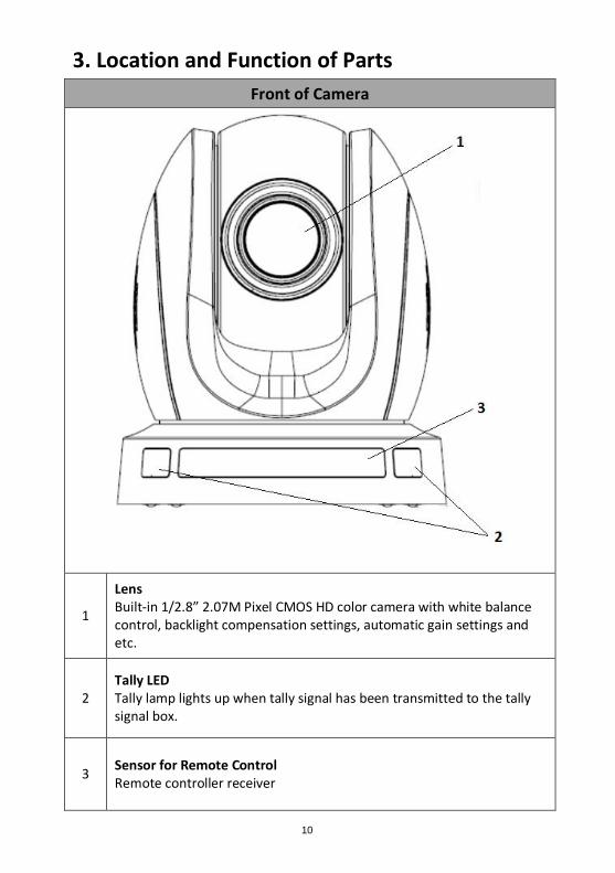
Lens Built-in 1/2.8” 2.07M Pixel CMOS HD color camera with white balance control, backlight compensation settings, automatic gain settings and etc.
2 Tally LED Tally lamp lights up when tally signal has been transmitted to the tally signal box.
3 Sensor for Remote Control Remote controller receiver
11
Rear of Camera
1
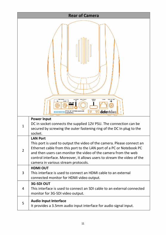
Power Input DC in socket connects the supplied 12V PSU. The connection can be secured by screwing the outer fastening ring of the DC In plug to the socket.
2
LAN Port This port is used to output the video of the camera. Please connect an Ethernet cable from this port to the LAN port of a PC or Notebook PC and then users can monitor the video of the camera from the web control interface. Moreover, it allows users to stream the video of the camera in various stream protocols.
3 HDMI OUT This interface is used to connect an HDMI cable to an external connected monitor for HDMI video output.
4 3G-SDI OUT This interface is used to connect an SDI cable to an external connected monitor for 3G-SDI video output.
5 Audio Input Interface It provides a 3.5mm audio input interface for audio signal input.
12
6
2 pin RS-485 Input Port This connector can be used for connecting to the RS-485 interface. Please use the 2pin Euroblock that is packaged with the PTC-140. Users can use a USB to RS-485 adapter cable to connect the PTC-140 camera to a PC. Note: The 38400 Baud rate is not available for the RS-485 now.
7 8 pin RS-232 Input Port Please connect an RS-232 Mini-Din 8 pin to RS-232 DB9 adapter cable from the camera to an RS-232 interface remote controller or PC.
8
8 pin RS-232 Output Port Please connect an R-232 Mini-Din 8 pin cable from this pin to the RS-232 Mini-Din 8 pin RS-232 input port of another PTC-140 camera for cascade connection.
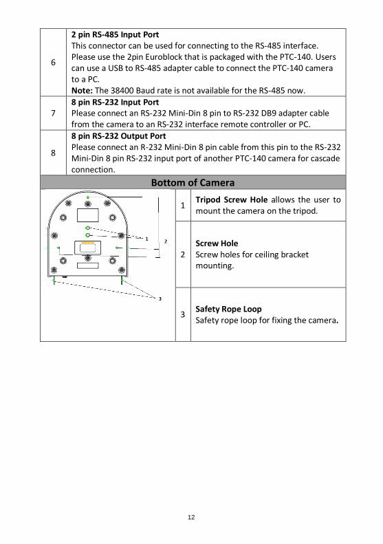
Bottom of Camera
1 Tripod Screw Hole allows the user to mount the camera on the tripod.
2 Screw Hole Screw holes for ceiling bracket mounting.
3 Safety Rope Loop Safety rope loop for fixing the camera.
13
4. Basic Setup
4.1 Power-On Initial Configuration
Step 1. Please connect the DC 12 V power adapter.
Step 2. The camera will start the initial configuration, the Red indicator light will be flashing.
Step 3. When the camera returns to the HOME position (middle position for P/T) and lens zoom-in/zoom-out is finished, the auto-testing is finished. The IR led will also stop flashing. If the preset 0 is set, camera will rotate to the 0 preset position after initial configuration.
4.2 Video Output
Network Output
Step 1. Please connect the PTC-140 to the PC/Notebook PC by an Ethernet cable.
Step 2. Please open your web browser and then enter the default IP address of the camera into the address bar.
Note: The default Static IP address of the PTC-140 is 192.168.5.163
Step 3. The Login page of the web control user interface will pop-up. Please enter user name and password (the default user name and password is admin/admin).
Step 4. After entering into the preview window, the preview screen of the video will be shown.
HDMI Video Output
Step 1. Please connect an HDMI cable from the HDMI OUT interface on the rear panel of the PTC-140 to an external connected monitor. When the self-test of the camera is finished, the video that is shot by the camera will be shown on the external connected monitor.
3G-SDI Video Output
Step 1. Please connect an SDI cable from the SDI OUT interface on the rear panel of the PTC-140 to an external connected monitor. When the self-test of

14
the camera is finished, the video that is shot by the camera will be shown on the external connected monitor.
15
5. Remote Control and On-Screen Menu
5.1 Remote Control Functions
No Item Description
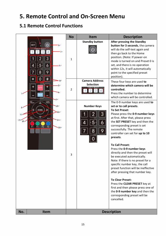
1
Standby button After pressing the Standby button for 3 seconds, the camera will do the self-test again and then go back to the Home position. (Note: If power-on mode is turned on and Preset 0 is set, and there is no operation within 12s, it will automatically point to the specified preset position).
2
Camera Address Selection
These four keys are used to determine which camera will be controlled. Press the number to determine which camera will be controlled.
3
Number Keys
The 0-9 number keys are used to set or to call presets. To Set Preset: Please press the 0-9 number keys at first. After that, please press the SET PRESET key and then the corresponding preset is set successfully. The remote controller can set for up to 10 presets. To Call Preset: Press the 0-9 number keys directly and then the preset will be executed automatically. Note: If there is no preset for a specific number key, the call preset function will be ineffective after pressing that number key. To Clear Preset: Press the CLEAR PRESET key at first and then please press one of the 0-9 number key and then the corresponding preset will be cancelled.
No. Item Description
16
4
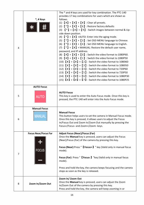
*, # Keys
The * and # keys are used for key combination. The PTC-140 provides 17 key combinations for users which are shown as follows. (1) 【#】+【#】+【#】: Clear all presets.
(2) 【*】+【#】+【6】: Restore factory defaults
(3) 【*】+【#】+【9】: Switch images between normal & Up-
side down position. (4) 【*】+【#】+AUTO: Enter into the aging mode.
(5) 【*】+【#】+【3】: Set OSD MENU language to Chinese.
(6) 【*】+【#】+【4】: Set OSD MENU language to English.
(7) 【*】+【#】+ MANUAL: Restore the default user name,
password, and IP address. (8) 【#】+【#】+【0】: Switch the video format to 1080P60.
(9) 【#】+【#】+【1】: Switch the video format to 1080P50
(10) 【#】+【#】+【2】: Switch the video format to 1080I60
(11) 【#】+【#】+【3】: Switch the video format to 1080I50
(12) 【#】+【#】+【4】: Switch the video format to 720P60
(13) 【#】+【#】+【5】: Switch the video format to 720P50
(14) 【#】+【#】+【6】: Switch the video format to 1080P30
(15) 【#】+【#】+【7】: Switch the video format to 1080P25
5
AUTO Focus
AUTO Focus This key is used to enter the Auto Focus mode. Once this key is pressed, the PTC-140 will enter into the Auto Focus mode.
6
Manual Focus
Manual Focus This button helps users to set the camera in Manual Focus mode. Once this key is pressed, it allows users to adjust the Focus In/Focus Out and Zoom In/Zoom Out manually by pressing the Focus+/Focus- and Zoom+/Zoom- keys.
7
Focus Near/Focus Far
Adjust Focus (Near)/Focus (Far) Once the Manual key is pressed, users can adjust the Focus (Near)/Focus (Far) of the camera by pressing this key.
Focus (Near):Press “【Focus+】” key (Valid only in manual focus mode).
Focus (Far): Press “【Focus-】”key (Valid only in manual focus mode).
Press and hold the key, the camera keeps focusing and the camera stops as soon as the key is released.
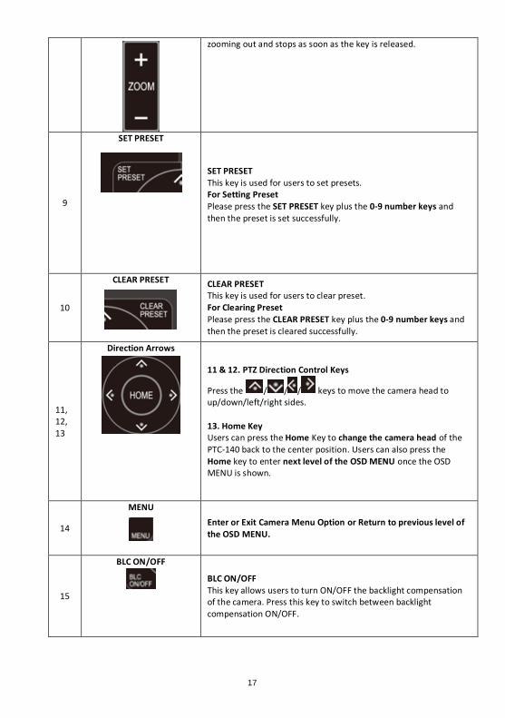
8 Zoom In/Zoom Out
Zoom In/ Zoom Out Once the Manual key is pressed, users can adjust the Zoom In/Zoom Out of the camera by pressing this key. Press and hold the key, the camera will keep zooming in or
17
zooming out and stops as soon as the key is released.
9
SET PRESET
SET PRESET This key is used for users to set presets. For Setting Preset Please press the SET PRESET key plus the 0-9 number keys and then the preset is set successfully.
10
CLEAR PRESET
CLEAR PRESET This key is used for users to clear preset. For Clearing Preset Please press the CLEAR PRESET key plus the 0-9 number keys and then the preset is cleared successfully.
11, 12, 13
Direction Arrows
11 & 12. PTZ Direction Control Keys
Press the / / / keys to move the camera head to up/down/left/right sides. 13. Home Key Users can press the Home Key to change the camera head of the PTC-140 back to the center position. Users can also press the Home key to enter next level of the OSD MENU once the OSD MENU is shown.
14
MENU Enter or Exit Camera Menu Option or Return to previous level of
the OSD MENU.
15
BLC ON/OFF
BLC ON/OFF This key allows users to turn ON/OFF the backlight compensation of the camera. Press this key to switch between backlight compensation ON/OFF.
18
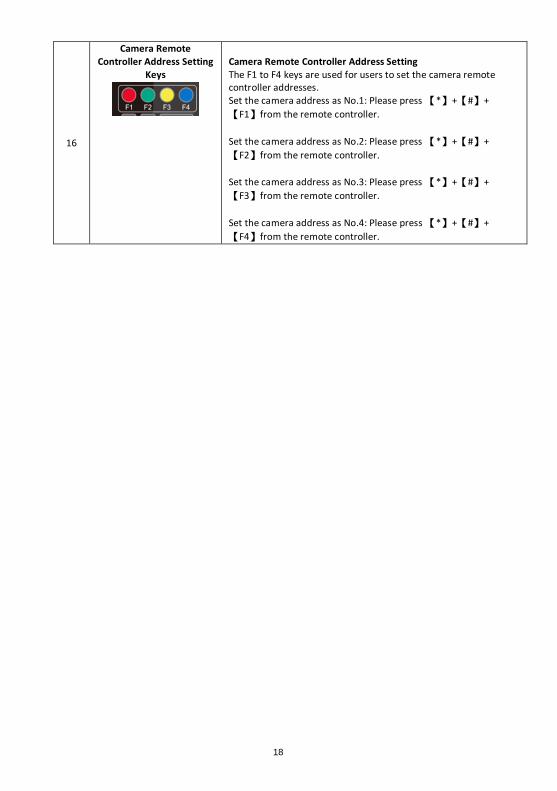
16
Camera Remote Controller Address Setting
Keys
Camera Remote Controller Address Setting The F1 to F4 keys are used for users to set the camera remote controller addresses. Set the camera address as No.1: Please press 【*】+【#】+
【F1】from the remote controller.
Set the camera address as No.2: Please press 【*】+【#】+
【F2】from the remote controller.
Set the camera address as No.3: Please press 【*】+【#】+
【F3】from the remote controller.
Set the camera address as No.4: Please press 【*】+【#】+
【F4】from the remote controller.
19
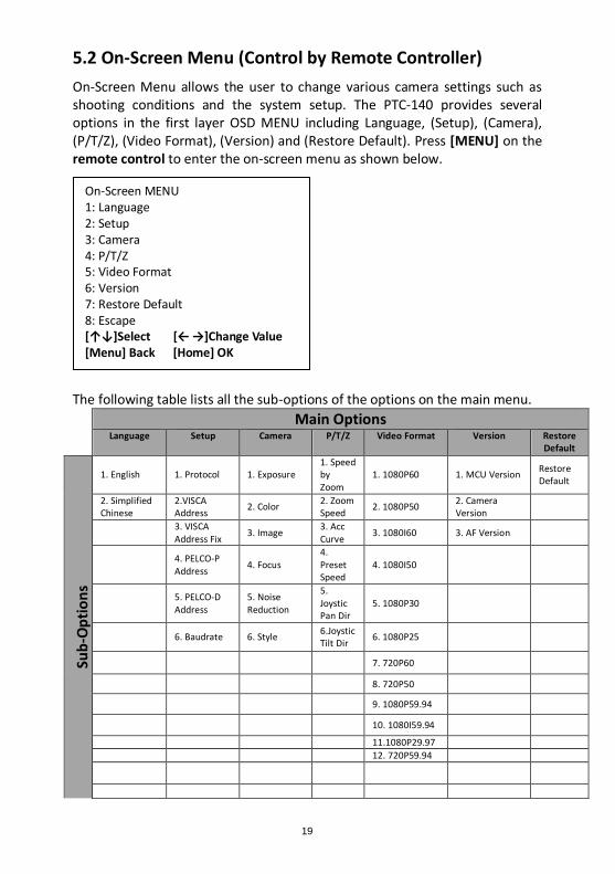
5.2 On-Screen Menu (Control by Remote Controller)
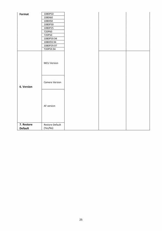
On-Screen Menu allows the user to change various camera settings such as shooting conditions and the system setup. The PTC-140 provides several options in the first layer OSD MENU including Language, (Setup), (Camera), (P/T/Z), (Video Format), (Version) and (Restore Default). Press [MENU] on the remote control to enter the on-screen menu as shown below.
The following table lists all the sub-options of the options on the main menu. Main Options
Language Setup Camera P/T/Z Video Format Version Restore Default
Sub
-Op
tio
ns
1. English 1. Protocol 1. Exposure 1. Speed by Zoom
1. 1080P60 1. MCU Version Restore Default
2. Simplified Chinese
2.VISCA Address
2. Color 2. Zoom Speed
2. 1080P50 2. Camera Version
3. VISCA Address Fix
3. Image 3. Acc Curve
3. 1080I60 3. AF Version
4. PELCO-P Address
4. Focus 4. Preset Speed
4. 1080I50
5. PELCO-D Address
5. Noise Reduction
5. Joystic Pan Dir
5. 1080P30
6. Baudrate 6. Style 6.Joystic Tilt Dir
6. 1080P25
7. 720P60
8. 720P50
9. 1080P59.94
10. 1080I59.94
11.1080P29.97
12. 720P59.94
On-Screen MENU 1: Language 2: Setup 3: Camera 4: P/T/Z 5: Video Format 6: Version 7: Restore Default 8: Escape [↑↓]Select [← →]Change Value [Menu] Back [Home] OK
20
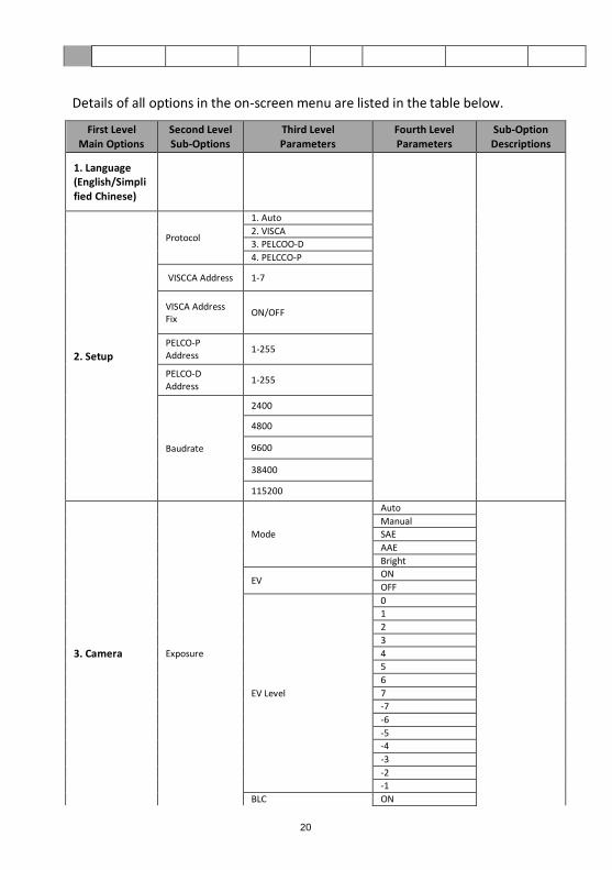
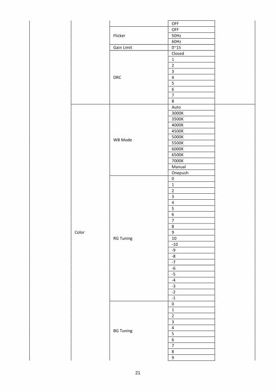
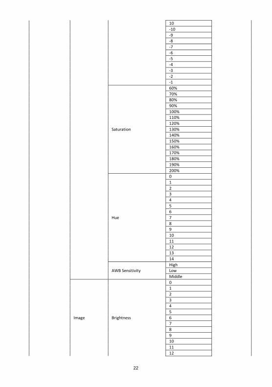
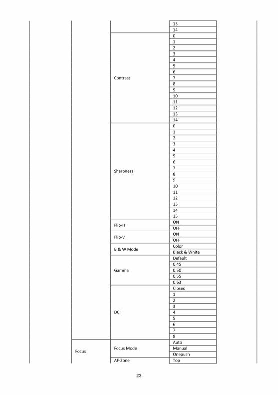
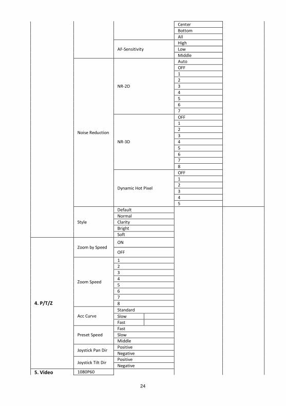
Details of all options in the on-screen menu are listed in the table below.
First Level Main Options
Second Level Sub-Options
Third Level Parameters
Fourth Level Parameters
Sub-Option Descriptions
1. Language (English/Simplified Chinese)
2. Setup
Protocol
1. Auto
2. VISCA
3. PELCOO-D
4. PELCCO-P
VISCCA Address 1-7
VISCA Address Fix
ON/OFF
PELCO-P Address
1-255
PELCO-D Address
1-255
Baudrate
2400
4800
9600
38400
115200
3. Camera Exposure
Mode
Auto
Manual
SAE
AAE
Bright
EV ON
OFF
EV Level
0
1
2
3
4
5
6
7
-7
-6
-5
-4
-3
-2
-1
BLC ON
21
OFF
Flicker
OFF
50Hz
60Hz
Gain Limit 0~15
DRC
Closed
1
2
3
4
5
6
7
8
Color
WB Mode
Auto
3000K
3500K
4000K
4500K
5000K
5500K
6000K
6500K
7000K
Manual
Onepush
RG Tuning
0
1
2
3
4
5
6
7
8
9
10
-10
-9
-8
-7
-6
-5
-4
-3
-2
-1
BG Tuning
0
1
2
3
4
5
6
7
8
9
22
10
-10
-9
-8
-7
-6
-5
-4
-3
-2
-1
Saturation
60%
70%
80%
90%
100%
110%
120%
130%
140%
150%
160%
170%
180%
190%
200%
Hue
0
1
2
3
4
5
6
7
8
9
10
11
12
13
14
AWB Sensitivity
High
Low
Middle
Image Brightness
0
1
2
3
4
5
6
7
8
9
10
11
12
23
13
14
Contrast
0
1
2
3
4
5
6
7
8
9
10
11
12
13
14
Sharpness
0
1
2
3
4
5
6
7
8
9
10
11
12
13
14
15
Flip-H ON
OFF
Flip-V ON
OFF
B & W Mode Color
Black & White
Gamma
Default
0.45
0.50
0.55
0.63
DCI
Closed
1
2
3
4
5
6
7
8
Focus Focus Mode
Auto
Manual
Onepush
AF-Zone Top
24
Center
Bottom
All
AF-Sensitivity
High
Low
Middle
Noise Reduction
NR-2D
Auto
OFF
1
2
3
4
5
6
7
NR-3D
OFF
1
2
3
4
5
6
7
8
Dynamic Hot Pixel
OFF
1
2
3
4
5
Style
Default
Normal
Clarity
Bright
Soft
4. P/T/Z
Zoom by Speed ON
OFF
Zoom Speed
1
2
3
4
5
6
7
8
Acc Curve
Standard
Slow
Fast
Preset Speed
Fast
Slow
Middle
Joystick Pan Dir Positive
Negative
Joystick Tilt Dir Positive
Negative
5. Video 1080P60
25
Format 1080P50
1080I60
1080I50
1080P30
1080P25
720P60
720P50
1080P59.94
1080I59.94
1080P29.97
720P59.94
6. Version
MCU Version
Camera Version
AF version
7. Restore Default
Restore Default (Yes/No)

26
6. Installation Instructions Note: The material for the ceiling mounting and vertical mounting of the
bracket is limited to the formwork or concrete and cannot be installed on the
plasterboard.
For the ceiling mount installation of the PTC-140, PA4*30 self-tapping screw x
4, PA4 plastic screw stopper x 4, PM3x5 screw x 6, ceiling upper covering plate
x 1, ceiling lower covering plate x 1 and PTC-140 camera x 1 are needed.
Step 1. The Ceiling Bracket, Ceiling Upper Cover Plate and Ceiling Lower
Covering Plate
The ceiling bracket is shown as following and it can be separated into
two parts including “ceiling upper covering plate” and “ceiling lower
covering plate”.
27
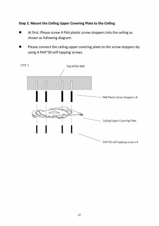
Step 2. Mount the Ceiling Upper Covering Plate to the Ceiling
At first, Please screw 4 PA4 plastic screw stoppers into the ceiling as
shown as following diagram.
Please connect the ceiling upper covering plate to the screw stoppers by
using 4 PA4*30 self-tapping screws.
28
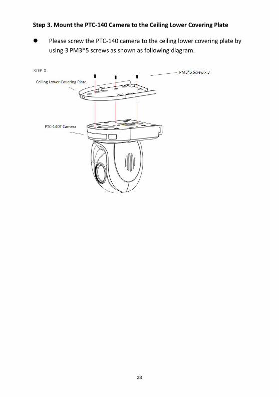
Step 3. Mount the PTC-140 Camera to the Ceiling Lower Covering Plate
Please screw the PTC-140 camera to the ceiling lower covering plate by
using 3 PM3*5 screws as shown as following diagram.
29
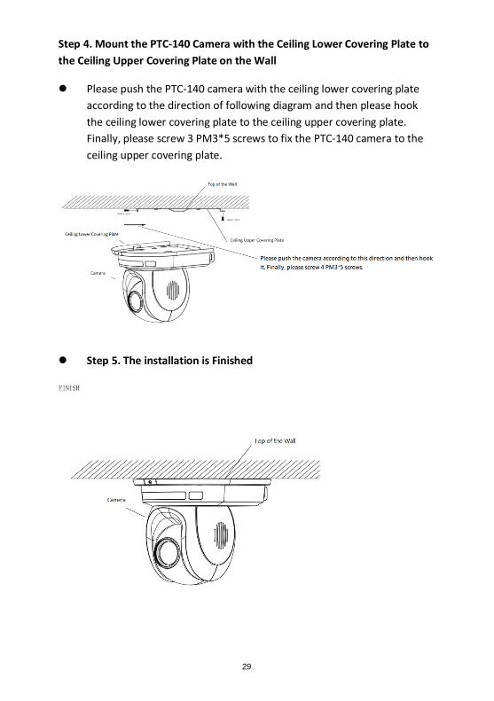
Step 4. Mount the PTC-140 Camera with the Ceiling Lower Covering Plate to
the Ceiling Upper Covering Plate on the Wall
Please push the PTC-140 camera with the ceiling lower covering plate
according to the direction of following diagram and then please hook
the ceiling lower covering plate to the ceiling upper covering plate.
Finally, please screw 3 PM3*5 screws to fix the PTC-140 camera to the
ceiling upper covering plate.
Step 5. The installation is Finished
30
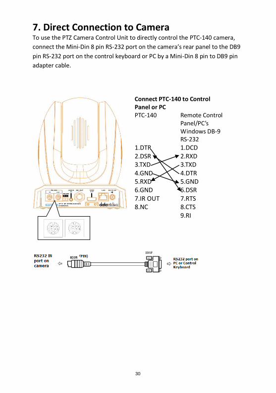
7. Direct Connection to Camera To use the PTZ Camera Control Unit to directly control the PTC-140 camera,
connect the Mini-Din 8 pin RS-232 port on the camera’s rear panel to the DB9
pin RS-232 port on the control keyboard or PC by a Mini-Din 8 pin to DB9 pin
adapter cable.
Connect PTC-140 to Control Panel or PC PTC-140 Remote Control
Panel/PC’s Windows DB-9 RS-232
1.DTR 1.DCD 2.DSR 2.RXD 3.TXD 3.TXD 4.GND 4.DTR 5.RXD 5.GND 6.GND 6.DSR 7.IR OUT 7.RTS 8.NC 8.CTS 9.RI
31
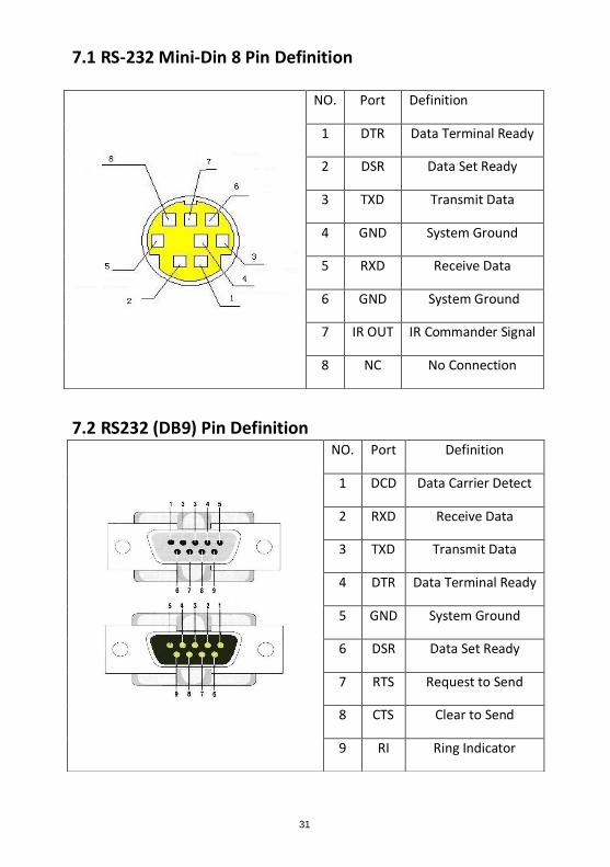
7.1 RS-232 Mini-Din 8 Pin Definition
7.2 RS232 (DB9) Pin Definition
NO. Port Definition
1 DTR Data Terminal Ready
2 DSR Data Set Ready
3 TXD Transmit Data
4 GND System Ground
5 RXD Receive Data
6 GND System Ground
7 IR OUT IR Commander Signal
8 NC No Connection
NO. Port Definition
1 DCD Data Carrier Detect
2 RXD Receive Data
3 TXD Transmit Data
4 DTR Data Terminal Ready
5 GND System Ground
6 DSR Data Set Ready
7 RTS Request to Send
8 CTS Clear to Send
9 RI Ring Indicator
32
8. PTC-140’s Web-Based User Interface 8.1 How to Connect the PTC-140 Camera to the PC
Users can connect the PTC-140 camera to the PC/Laptop in Static IP mode and
DHCP mode. The default static IP address of the PTC-140 is 192.168.5.163.
Please see following steps for connecting the PTC-140 camera to the network
for using the web-based user interface of the PTC-140.
8.1.1 Connect the Camera to the PC in DHCP Mode
Please follow following steps for connecting the PTC-140 camera to the PC in DHCP Mode. Step 1. Please connect a 12V power adapter to the DC IN 12V interface on the
rear panel of the PTC-140.
Step 2. Please use an RJ-45 Ethernet cable to connect the WAN port of a
router to an RJ-45 port of the public network.
Step 3. Please connect an RJ-45 Ethernet cable from the LAN interface on the
rear panel of the PTC-140 to the RJ-45 Ethernet port of a router.
Step 4. Please use an HDMI cable to connect from the HDMI OUT interface on
the rear panel of the PTC-140 to the HDMI IN interface of an external
connected monitor.
Step 5. You can see the IP address and the IR address of the PTC-140-T will be
shown on the top-left side of the screen.
Step 6. Please connect an RJ-45 Ethernet cable from the RJ-45 port of your PC
to the LAN port of the router.
33
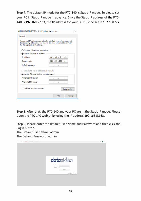
Step 7. The default IP mode for the PTC-140 is Static IP mode. So please set
your PC in Static IP mode in advance. Since the Static IP address of the PTC-
140 is 192.168.5.163, the IP address for your PC must be set in 192.168.5.x
Step 8. After that, the PTC-140 and your PC are in the Static IP mode. Please open the PTC-140 web UI by using the IP address 192.168.5.163. Step 9. Please enter the default User Name and Password and then click the Login button. The Default User Name: admin The Default Password: admin
34
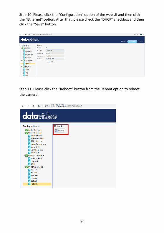
Step 10. Please click the “Configuration” option of the web UI and then click the “Ethernet” option. After that, please check the “DHCP” checkbox and then click the “Save” button.
Step 11. Please click the “Reboot” button from the Reboot option to reboot
the camera.
35
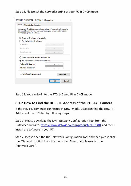
Step 12. Please set the network setting of your PC in DHCP mode.
Step 13. You can login to the PTC-140 web UI in DHCP mode.
8.1.2 How to Find the DHCP IP Address of the PTC-140 Camera
If the PTC-140 camera is connected in DHCP mode, users can find the DHCP IP
Address of the PTC-140 by following steps.
Step 1. Please download the DVIP Network Configuration Tool from the
Datavideo website. https://www.datavideo.com/product/PTC-140T and then
install the software in your PC.
Step 2. Please open the DVIP Network Configuration Tool and then please click
the “Network” option from the menu bar. After that, please click the
“Network Card”.
36
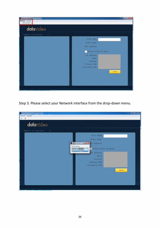
Step 3. Please select your Network interface from the drop-down menu.
37
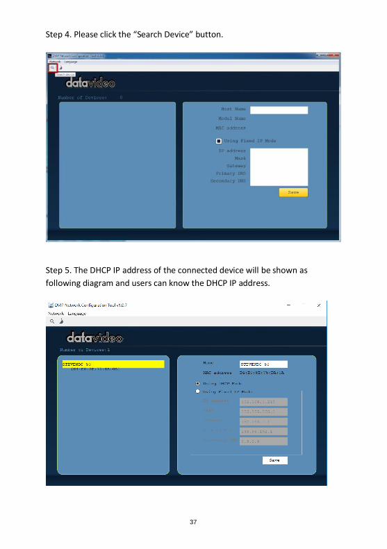
Step 4. Please click the “Search Device” button.
Step 5. The DHCP IP address of the connected device will be shown as
following diagram and users can know the DHCP IP address.
38
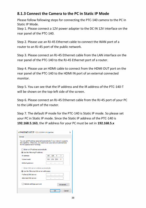
8.1.3 Connect the Camera to the PC in Static IP Mode
Please follow following steps for connecting the PTC-140 camera to the PC in Static IP Mode. Step 1. Please connect a 12V power adapter to the DC IN 12V interface on the
rear panel of the PTC-140.
Step 2. Please use an RJ-45 Ethernet cable to connect the WAN port of a
router to an RJ-45 port of the public network.
Step 3. Please connect an RJ-45 Ethernet cable from the LAN interface on the
rear panel of the PTC-140 to the RJ-45 Ethernet port of a router.
Step 4. Please use an HDMI cable to connect from the HDMI OUT port on the
rear panel of the PTC-140 to the HDMI IN port of an external connected
monitor.
Step 5. You can see that the IP address and the IR address of the PTC-140-T
will be shown on the top-left side of the screen.
Step 6. Please connect an RJ-45 Ethernet cable from the RJ-45 port of your PC
to the LAN port of the router.
Step 7. The default IP mode for the PTC-140 is Static IP mode. So please set
your PC in Static IP mode. Since the Static IP address of the PTC-140 is
192.168.5.163, the IP address for your PC must be set in 192.168.5.x
39
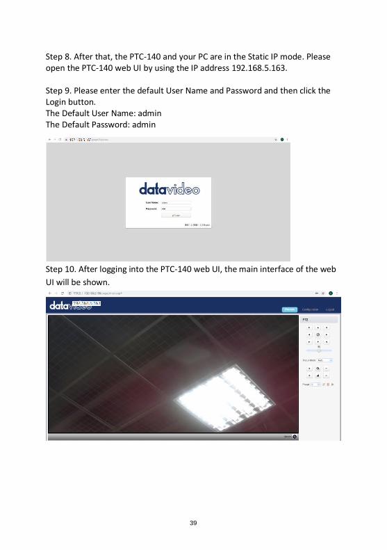
Step 8. After that, the PTC-140 and your PC are in the Static IP mode. Please open the PTC-140 web UI by using the IP address 192.168.5.163. Step 9. Please enter the default User Name and Password and then click the Login button. The Default User Name: admin The Default Password: admin
Step 10. After logging into the PTC-140 web UI, the main interface of the web
UI will be shown.
40
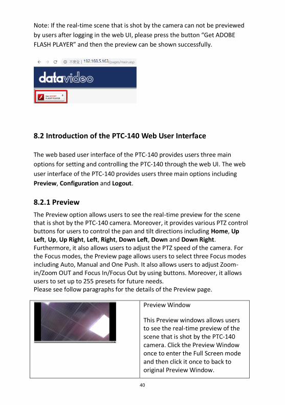
Note: If the real-time scene that is shot by the camera can not be previewed
by users after logging in the web UI, please press the button “Get ADOBE
FLASH PLAYER” and then the preview can be shown successfully.
8.2 Introduction of the PTC-140 Web User Interface
The web based user interface of the PTC-140 provides users three main
options for setting and controlling the PTC-140 through the web UI. The web
user interface of the PTC-140 provides users three main options including
Preview, Configuration and Logout.
8.2.1 Preview
The Preview option allows users to see the real-time preview for the scene that is shot by the PTC-140 camera. Moreover, it provides various PTZ control buttons for users to control the pan and tilt directions including Home, Up Left, Up, Up Right, Left, Right, Down Left, Down and Down Right. Furthermore, it also allows users to adjust the PTZ speed of the camera. For the Focus modes, the Preview page allows users to select three Focus modes including Auto, Manual and One Push. It also allows users to adjust Zoom-in/Zoom OUT and Focus In/Focus Out by using buttons. Moreover, it allows users to set up to 255 presets for future needs. Please see follow paragraphs for the details of the Preview page.
Preview Window
This Preview windows allows users to see the real-time preview of the scene that is shot by the PTC-140 camera. Click the Preview Window once to enter the Full Screen mode and then click it once to back to original Preview Window.
41
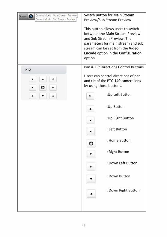
Switch Button for Main Stream Preview/Sub Stream Preview
This button allows users to switch between the Main Stream Preview and Sub Stream Preview. The parameters for main stream and sub stream can be set from the Video Encode option in the Configuration option.
Pan & Tilt Directions Control Buttons
Users can control directions of pan and tilt of the PTC-140 camera lens by using those buttons.
:Up Left Button
:Up Button
:Up Right Button
: Left Button
: Home Button
: Right Button
: Down Left Button
: Down Button
: Down Right Button
42
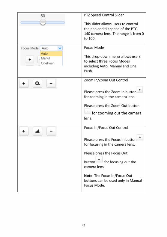
PTZ Speed Control Slider
This slider allows users to control the pan and tilt speed of the PTC-140 camera lens. The range is from 0 to 100.
Focus Mode
This drop-down menu allows users to select three Focus Modes including Auto, Manual and One Push.
Zoom In/Zoom Out Control
Please press the Zoom In button for zooming in the camera lens.
Please press the Zoom Out button
for zooming out the camera lens.
Focus In/Focus Out Control
Please press the Focus In button for focusing in the camera lens.
Please press the Focus Out
button for focusing out the camera lens.
Note: The Focus In/Focus Out buttons can be used only in Manual Focus Mode.
43
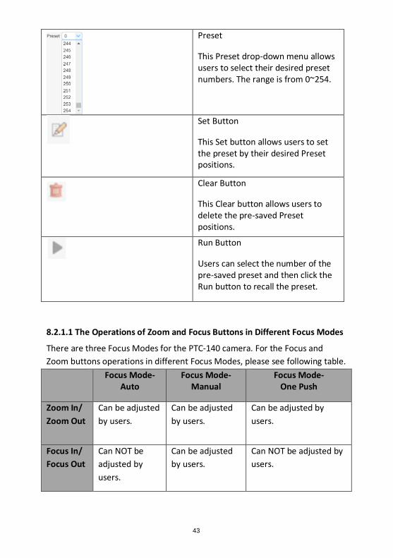
Preset
This Preset drop-down menu allows users to select their desired preset numbers. The range is from 0~254.
Set Button
This Set button allows users to set the preset by their desired Preset positions.
Clear Button
This Clear button allows users to delete the pre-saved Preset positions.
Run Button
Users can select the number of the pre-saved preset and then click the Run button to recall the preset.
8.2.1.1 The Operations of Zoom and Focus Buttons in Different Focus Modes
There are three Focus Modes for the PTC-140 camera. For the Focus and
Zoom buttons operations in different Focus Modes, please see following table.
Focus Mode-Auto
Focus Mode- Manual
Focus Mode- One Push
Zoom In/
Zoom Out
Can be adjusted
by users.
Can be adjusted
by users.
Can be adjusted by
users.
Focus In/
Focus Out
Can NOT be
adjusted by
users.
Can be adjusted
by users.
Can NOT be adjusted by
users.
44
8.2.1.2 How to Set the Preset Positon
Please follow following steps for setting your desired preset.
Step 1. Please adjust the pan and tilt of the PTC-140 camera to your desired
position.
Step 2. Please make sure that other parameters including Zoom, Focus and
those parameters in the Configuration option are set in advance.
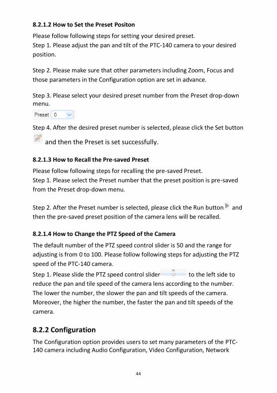
Step 3. Please select your desired preset number from the Preset drop-down menu.
Step 4. After the desired preset number is selected, please click the Set button
and then the Preset is set successfully.
8.2.1.3 How to Recall the Pre-saved Preset
Please follow following steps for recalling the pre-saved Preset.
Step 1. Please select the Preset number that the preset position is pre-saved
from the Preset drop-down menu.
Step 2. After the Preset number is selected, please click the Run button and
then the pre-saved preset position of the camera lens will be recalled.
8.2.1.4 How to Change the PTZ Speed of the Camera
The default number of the PTZ speed control slider is 50 and the range for
adjusting is from 0 to 100. Please follow following steps for adjusting the PTZ
speed of the PTC-140 camera.
Step 1. Please slide the PTZ speed control slider to the left side to
reduce the pan and tile speed of the camera lens according to the number.
The lower the number, the slower the pan and tilt speeds of the camera.
Moreover, the higher the number, the faster the pan and tilt speeds of the
camera.
8.2.2 Configuration
The Configuration option provides users to set many parameters of the PTC-140 camera including Audio Configuration, Video Configuration, Network
45
Configuration and System Configuration. There are several parameters for each configuration, please see following paragraphs for more details.
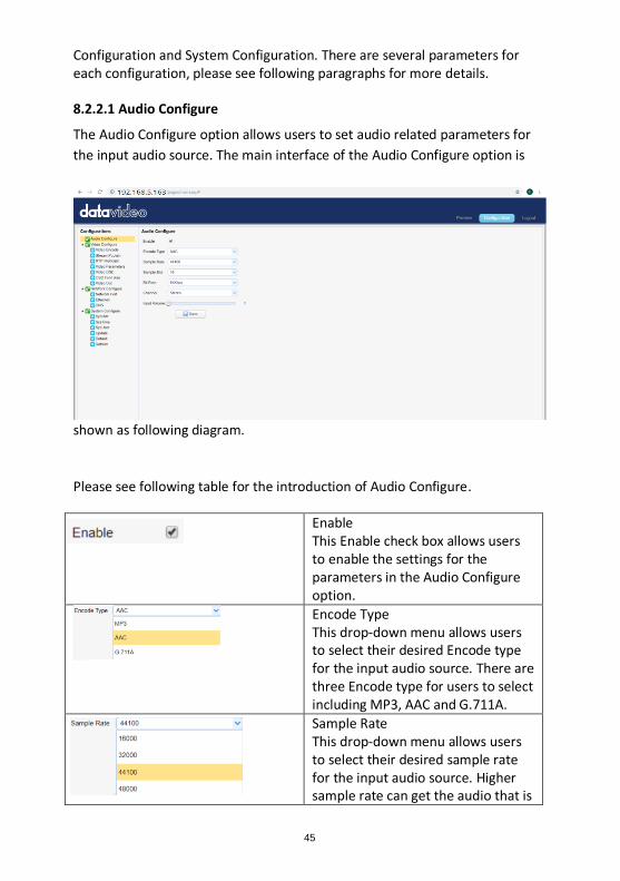
8.2.2.1 Audio Configure
The Audio Configure option allows users to set audio related parameters for
the input audio source. The main interface of the Audio Configure option is
shown as following diagram.
Please see following table for the introduction of Audio Configure.
Enable This Enable check box allows users to enable the settings for the parameters in the Audio Configure option.
Encode Type This drop-down menu allows users to select their desired Encode type for the input audio source. There are three Encode type for users to select including MP3, AAC and G.711A.
Sample Rate This drop-down menu allows users to select their desired sample rate for the input audio source. Higher sample rate can get the audio that is
46
closer to the original audio source.
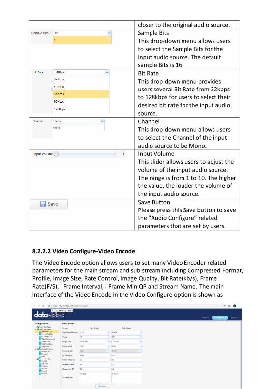
Sample Bits This drop-down menu allows users to select the Sample Bits for the input audio source. The default sample Bits is 16.
Bit Rate This drop-down menu provides users several Bit Rate from 32kbps to 128kbps for users to select their desired bit rate for the input audio source.
Channel This drop-down menu allows users to select the Channel of the input audio source to be Mono.
Input Volume This slider allows users to adjust the volume of the input audio source. The range is from 1 to 10. The higher the value, the louder the volume of the input audio source.
Save Button Please press this Save button to save the “Audio Configure” related parameters that are set by users.
8.2.2.2 Video Configure-Video Encode
The Video Encode option allows users to set many Video Encoder related parameters for the main stream and sub stream including Compressed Format, Profile, Image Size, Rate Control, Image Quality, Bit Rate(kb/s), Frame Rate(F/S), I Frame Interval, I Frame Min QP and Stream Name. The main interface of the Video Encode in the Video Configure option is shown as
47
following diagram.
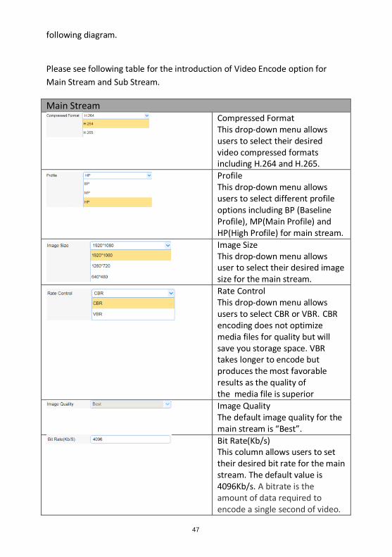
Please see following table for the introduction of Video Encode option for
Main Stream and Sub Stream.
Main Stream
Compressed Format This drop-down menu allows users to select their desired video compressed formats including H.264 and H.265.
Profile This drop-down menu allows users to select different profile options including BP (Baseline Profile), MP(Main Profile) and HP(High Profile) for main stream.
Image Size This drop-down menu allows user to select their desired image size for the main stream.
Rate Control This drop-down menu allows users to select CBR or VBR. CBR encoding does not optimize media files for quality but will save you storage space. VBR takes longer to encode but produces the most favorable results as the quality of the media file is superior
Image Quality The default image quality for the main stream is “Best”.
Bit Rate(Kb/s) This column allows users to set their desired bit rate for the main stream. The default value is 4096Kb/s. A bitrate is the amount of data required to encode a single second of video.
48
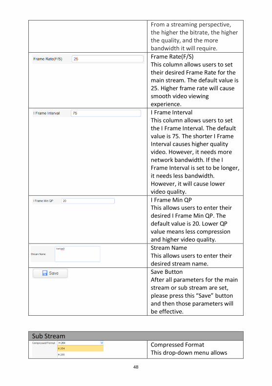
From a streaming perspective, the higher the bitrate, the higher the quality, and the more bandwidth it will require.
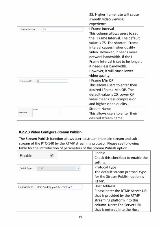
Frame Rate(F/S) This column allows users to set their desired Frame Rate for the main stream. The default value is 25. Higher frame rate will cause smooth video viewing experience.
I Frame Interval This column allows users to set the I Frame Interval. The default value is 75. The shorter I Frame Interval causes higher quality video. However, it needs more network bandwidth. If the I Frame Interval is set to be longer, it needs less bandwidth. However, it will cause lower video quality.
I Frame Min QP This allows users to enter their desired I Frame Min QP. The default value is 20. Lower QP value means less compression and higher video quality.
Stream Name This allows users to enter their desired stream name.
Save Button After all parameters for the main stream or sub stream are set, please press this “Save” button and then those parameters will be effective.
Sub Stream
Compressed Format This drop-down menu allows
49
users to select their desired video compressed formats including H.264 and H.265.
Profile This drop-down menu allows users to select profile. The default profile for the sub stream is BP.
Image Size This drop-down menu allows user to select their desired image size for the sub stream.
Rate Control This drop-down menu allows users to select CBR or VBR. CBR encoding does not optimize media files for quality but will save you storage space. VBR takes longer to encode but produces the most favorable results as the quality of the media file is superior
Image Quality The default image quality for the main stream is “Better”.
Bit Rate(Kb/s) This column allows users to set their desired bit rate for the main stream. The default value is 512Kb/s. A bitrate is the amount of data required to encode a single second of video. From a streaming perspective, the higher the bitrate, the higher the quality, and the more bandwidth it will require.
Frame Rate(F/S) This column allows users to set their desired Frame Rate for the main stream. The default value is
50
25. Higher frame rate will cause smooth video viewing experience.
I Frame Interval This column allows users to set the I Frame Interval. The default value is 75. The shorter I Frame Interval causes higher quality video. However, it needs more network bandwidth. If the I Frame Interval is set to be longer, it needs less bandwidth. However, it will cause lower video quality.
I Frame Min QP This allows users to enter their desired I Frame Min QP. The default value is 20. Lower QP value means less compression and higher video quality.
Stream Name This allows users to enter their desired stream name.
8.2.2.3 Video Configure-Stream Publish
The Stream Publish function allows user to stream the main stream and sub stream of the PTC-140 by the RTMP streaming protocol. Please see following table for the introduction of parameters of the Stream Publish option.
Enable Check this checkbox to enable the setting.
Protocol Type The default stream protocol type for the Stream Publish option is RTMP.
Host Address Please enter the RTMP Server URL that is provided by the RTMP streaming platform into this column. Note: The Server URL that is entered into the Host
51
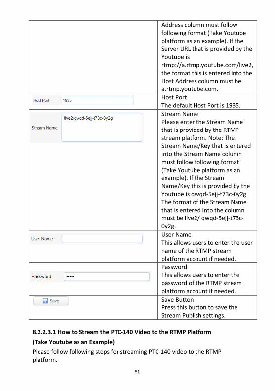
Address column must follow following format (Take Youtube platform as an example). If the Server URL that is provided by the Youtube is rtmp://a.rtmp.youtube.com/live2, the format this is entered into the Host Address column must be a.rtmp.youtube.com.
Host Port The default Host Port is 1935.
Stream Name Please enter the Stream Name that is provided by the RTMP stream platform. Note: The Stream Name/Key that is entered into the Stream Name column must follow following format (Take Youtube platform as an example). If the Stream Name/Key this is provided by the Youtube is qwqd-5ejj-t73c-0y2g. The format of the Stream Name that is entered into the column must be live2/ qwqd-5ejj-t73c-0y2g.
User Name This allows users to enter the user name of the RTMP stream platform account if needed.
Password This allows users to enter the password of the RTMP stream platform account if needed.
Save Button Press this button to save the Stream Publish settings.
8.2.2.3.1 How to Stream the PTC-140 Video to the RTMP Platform
(Take Youtube as an Example)
Please follow following steps for streaming PTC-140 video to the RTMP platform.
52
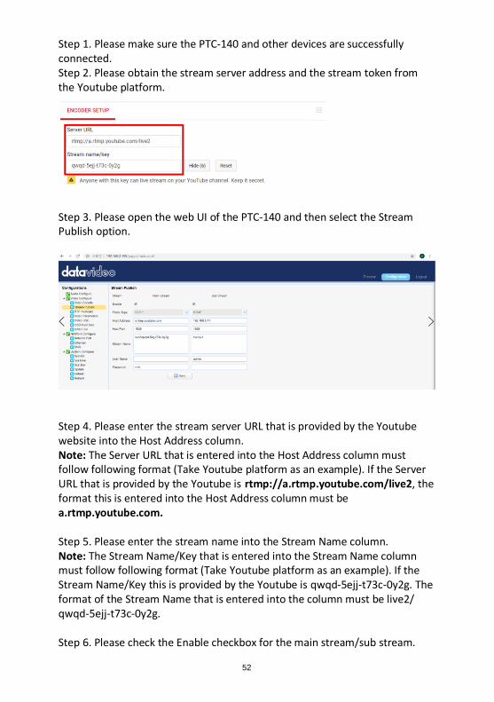
Step 1. Please make sure the PTC-140 and other devices are successfully connected. Step 2. Please obtain the stream server address and the stream token from the Youtube platform.
Step 3. Please open the web UI of the PTC-140 and then select the Stream Publish option.
Step 4. Please enter the stream server URL that is provided by the Youtube website into the Host Address column. Note: The Server URL that is entered into the Host Address column must follow following format (Take Youtube platform as an example). If the Server URL that is provided by the Youtube is rtmp://a.rtmp.youtube.com/live2, the format this is entered into the Host Address column must be a.rtmp.youtube.com. Step 5. Please enter the stream name into the Stream Name column. Note: The Stream Name/Key that is entered into the Stream Name column must follow following format (Take Youtube platform as an example). If the Stream Name/Key this is provided by the Youtube is qwqd-5ejj-t73c-0y2g. The format of the Stream Name that is entered into the column must be live2/ qwqd-5ejj-t73c-0y2g. Step 6. Please check the Enable checkbox for the main stream/sub stream.
53
Step 7. Please press the save button and then the streaming can be done successfully through the Youtube platform. 8.2.2.3.2 How to Stream the PTC-140 Video to the RTMP Platform
(Take Facebook as an Example)
Step 1. Please use an RJ-45 Ethernet cable to connect one end to the public network and then connect another end to the WAN port of a router.
Step 2. Please use another RJ-45 Ethernet cable to connect one end to the
LAN port on the rear panel of the PTC-140 camera and then connect another
end to one of the LAN port of the router.
Step 3. Please use another RJ-45 Ethernet cable to connect one end to the
LAN port of the PC/Laptop and then connect another end to the LAN port of a
router.
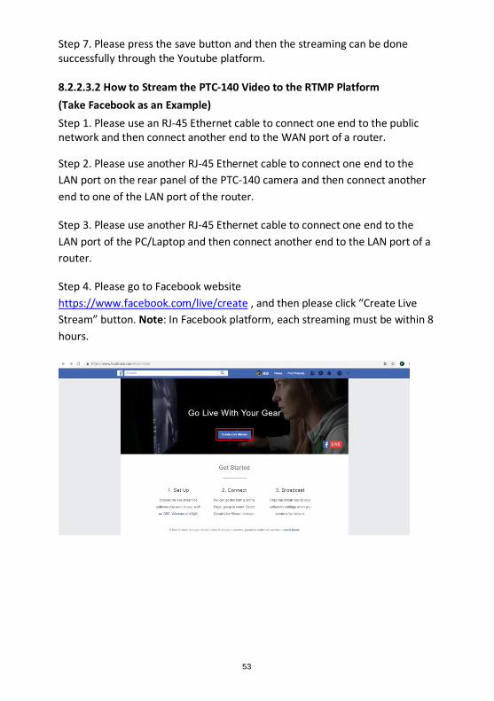
Step 4. Please go to Facebook website
https://www.facebook.com/live/create , and then please click “Create Live
Stream” button. Note: In Facebook platform, each streaming must be within 8
hours.
54
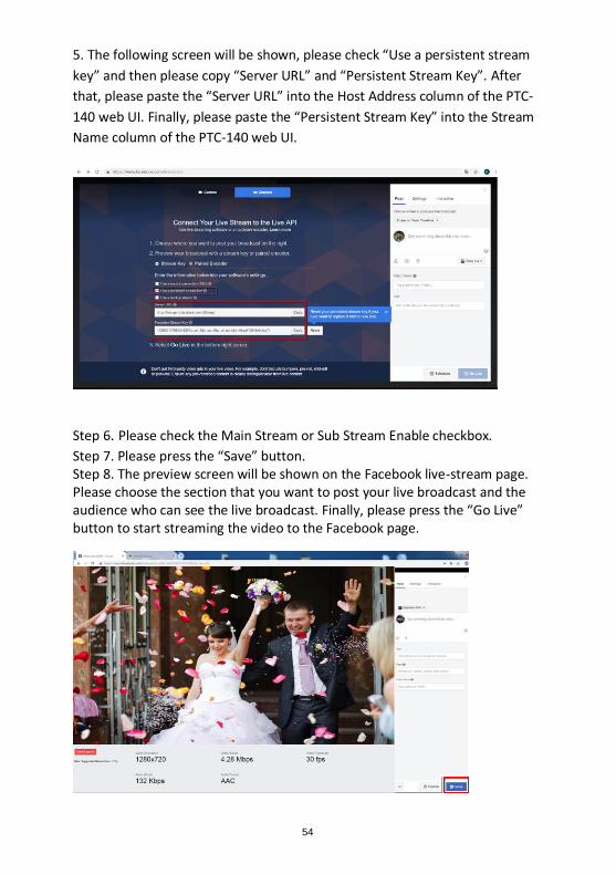
5. The following screen will be shown, please check “Use a persistent stream
key” and then please copy “Server URL” and “Persistent Stream Key”. After
that, please paste the “Server URL” into the Host Address column of the PTC-
140 web UI. Finally, please paste the “Persistent Stream Key” into the Stream
Name column of the PTC-140 web UI.
Step 6. Please check the Main Stream or Sub Stream Enable checkbox.
Step 7. Please press the “Save” button. Step 8. The preview screen will be shown on the Facebook live-stream page. Please choose the section that you want to post your live broadcast and the audience who can see the live broadcast. Finally, please press the “Go Live” button to start streaming the video to the Facebook page.
55
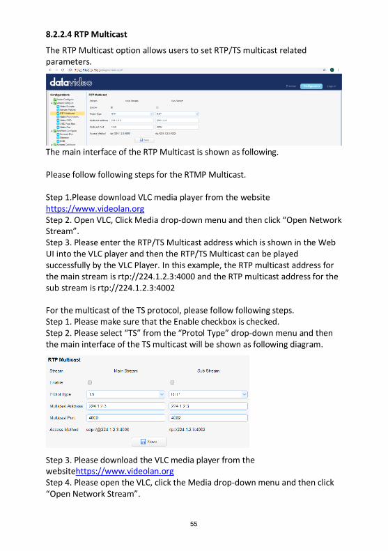
8.2.2.4 RTP Multicast
The RTP Multicast option allows users to set RTP/TS multicast related parameters.
The main interface of the RTP Multicast is shown as following. Please follow following steps for the RTMP Multicast. Step 1.Please download VLC media player from the website https://www.videolan.org Step 2. Open VLC, Click Media drop-down menu and then click “Open Network Stream”. Step 3. Please enter the RTP/TS Multicast address which is shown in the Web UI into the VLC player and then the RTP/TS Multicast can be played successfully by the VLC Player. In this example, the RTP multicast address for the main stream is rtp://224.1.2.3:4000 and the RTP multicast address for the sub stream is rtp://224.1.2.3:4002 For the multicast of the TS protocol, please follow following steps. Step 1. Please make sure that the Enable checkbox is checked. Step 2. Please select “TS” from the “Protol Type” drop-down menu and then the main interface of the TS multicast will be shown as following diagram.
Step 3. Please download the VLC media player from the websitehttps://www.videolan.org Step 4. Please open the VLC, click the Media drop-down menu and then click “Open Network Stream”.
56
Step 5. Please enter the TS Multicast Address that is shown in the web control interface into the VLC player and then users can use the VLC player to play the RTP/TS multicast. In this example, the TS multicast address for the for the main stream is udp://@224.1.2.3:4000
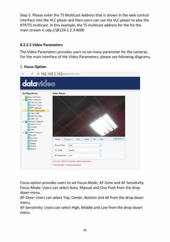
8.2.2.5 Video Parameters
The Video Parameters provides users to set many parameter for the cameras. For the main interface of the Video Parameters, please see following diagrams. 1. Focus Option
Focus option provides users to set Focus Mode, AF-Zone and AF-Sensitivity. Focus Mode: Users can select Auto, Manual and One Push from the drop down menu. AF-Zone: Users can select Top, Center, Bottom and All from the drop down menu. AF-Sensitivity: Users can select High, Middle and Low from the drop-down menu.
57
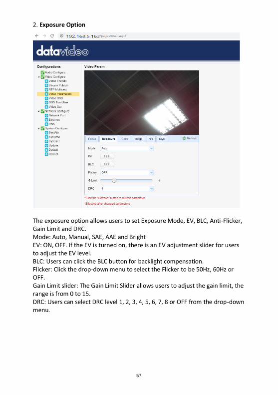
2. Exposure Option
The exposure option allows users to set Exposure Mode, EV, BLC, Anti-Flicker, Gain Limit and DRC. Mode: Auto, Manual, SAE, AAE and Bright EV: ON, OFF. If the EV is turned on, there is an EV adjustment slider for users to adjust the EV level. BLC: Users can click the BLC button for backlight compensation. Flicker: Click the drop-down menu to select the Flicker to be 50Hz, 60Hz or OFF. Gain Limit slider: The Gain Limit Slider allows users to adjust the gain limit, the range is from 0 to 15. DRC: Users can select DRC level 1, 2, 3, 4, 5, 6, 7, 8 or OFF from the drop-down menu.
58
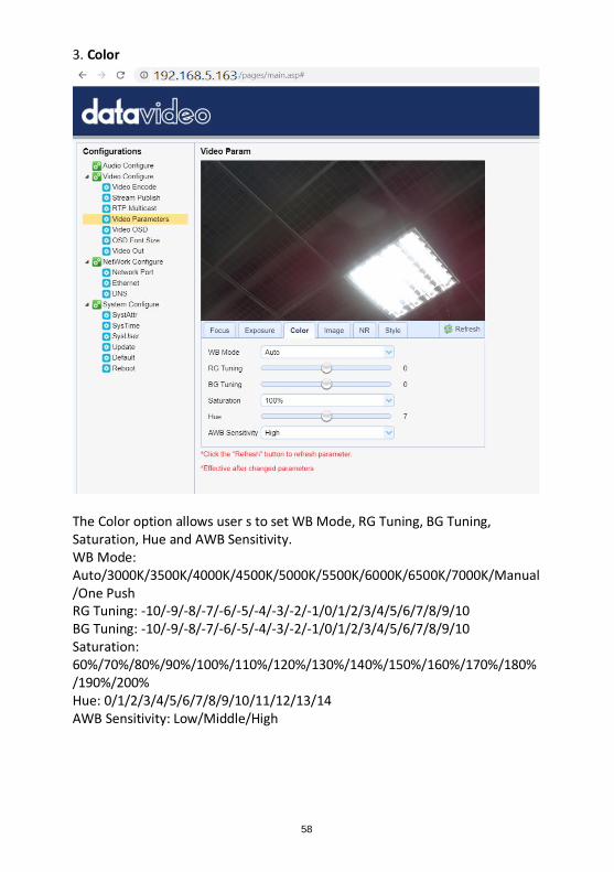
3. Color
The Color option allows user s to set WB Mode, RG Tuning, BG Tuning, Saturation, Hue and AWB Sensitivity. WB Mode: Auto/3000K/3500K/4000K/4500K/5000K/5500K/6000K/6500K/7000K/Manual/One Push RG Tuning: -10/-9/-8/-7/-6/-5/-4/-3/-2/-1/0/1/2/3/4/5/6/7/8/9/10 BG Tuning: -10/-9/-8/-7/-6/-5/-4/-3/-2/-1/0/1/2/3/4/5/6/7/8/9/10 Saturation: 60%/70%/80%/90%/100%/110%/120%/130%/140%/150%/160%/170%/180%/190%/200% Hue: 0/1/2/3/4/5/6/7/8/9/10/11/12/13/14 AWB Sensitivity: Low/Middle/High
59
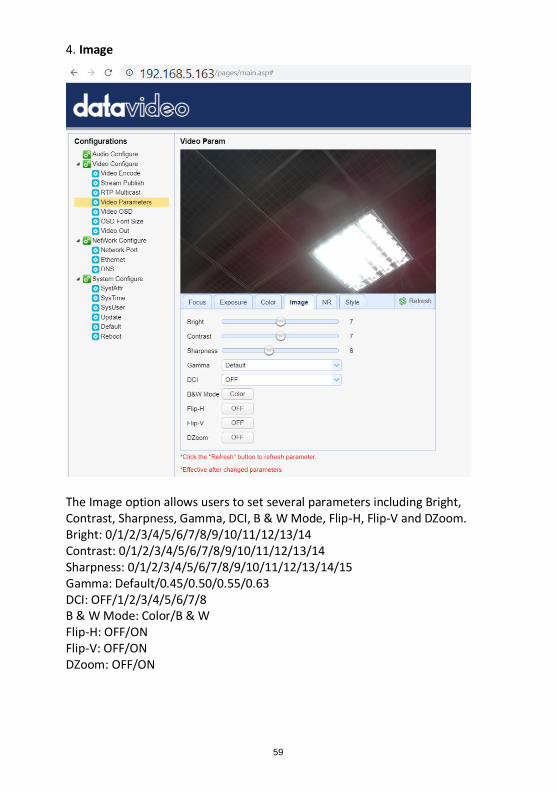
4. Image
The Image option allows users to set several parameters including Bright, Contrast, Sharpness, Gamma, DCI, B & W Mode, Flip-H, Flip-V and DZoom. Bright: 0/1/2/3/4/5/6/7/8/9/10/11/12/13/14 Contrast: 0/1/2/3/4/5/6/7/8/9/10/11/12/13/14 Sharpness: 0/1/2/3/4/5/6/7/8/9/10/11/12/13/14/15 Gamma: Default/0.45/0.50/0.55/0.63 DCI: OFF/1/2/3/4/5/6/7/8 B & W Mode: Color/B & W Flip-H: OFF/ON Flip-V: OFF/ON DZoom: OFF/ON
60
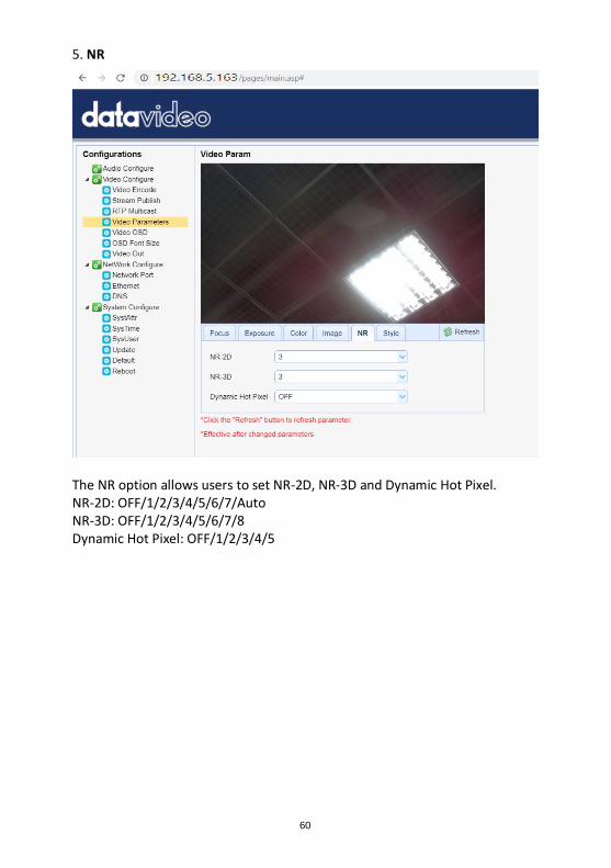
5. NR
The NR option allows users to set NR-2D, NR-3D and Dynamic Hot Pixel. NR-2D: OFF/1/2/3/4/5/6/7/Auto NR-3D: OFF/1/2/3/4/5/6/7/8 Dynamic Hot Pixel: OFF/1/2/3/4/5
61
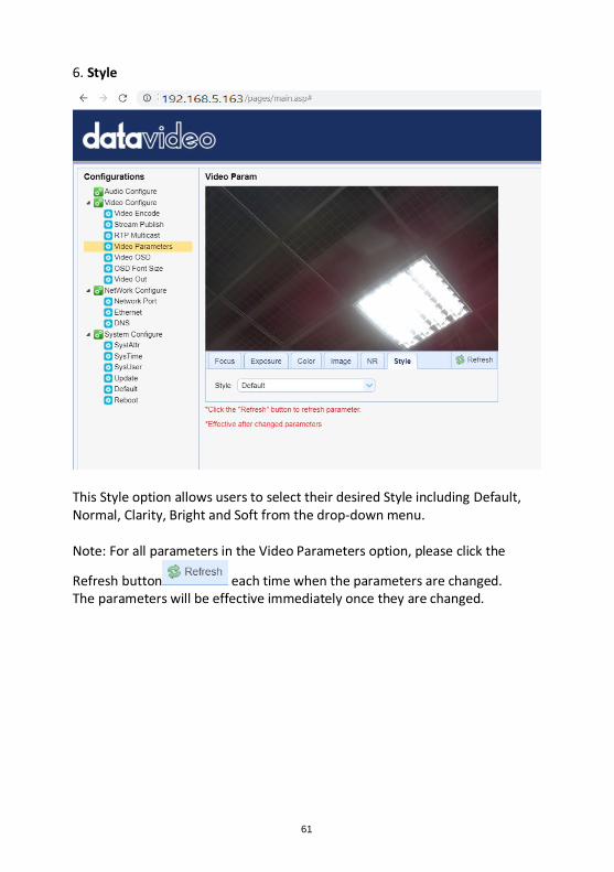
6. Style
This Style option allows users to select their desired Style including Default, Normal, Clarity, Bright and Soft from the drop-down menu. Note: For all parameters in the Video Parameters option, please click the
Refresh button each time when the parameters are changed. The parameters will be effective immediately once they are changed.
62
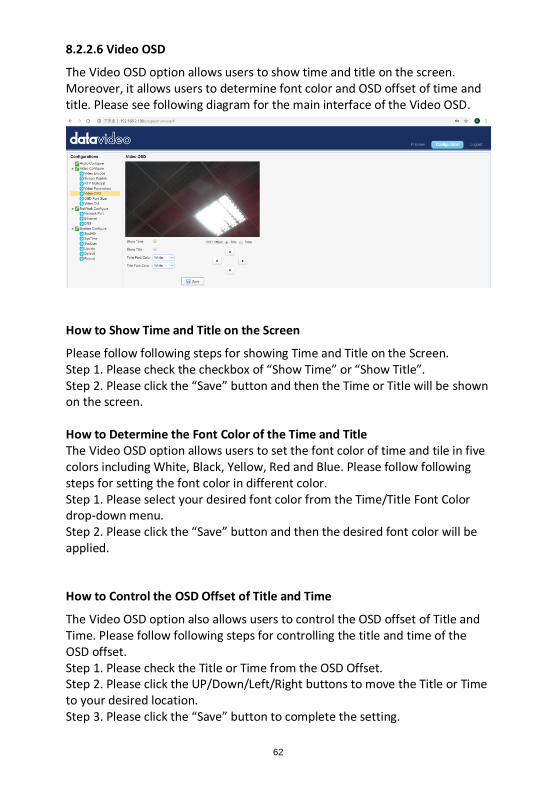
8.2.2.6 Video OSD
The Video OSD option allows users to show time and title on the screen. Moreover, it allows users to determine font color and OSD offset of time and title. Please see following diagram for the main interface of the Video OSD.
How to Show Time and Title on the Screen
Please follow following steps for showing Time and Title on the Screen. Step 1. Please check the checkbox of “Show Time” or “Show Title”. Step 2. Please click the “Save” button and then the Time or Title will be shown on the screen. How to Determine the Font Color of the Time and Title The Video OSD option allows users to set the font color of time and tile in five colors including White, Black, Yellow, Red and Blue. Please follow following steps for setting the font color in different color. Step 1. Please select your desired font color from the Time/Title Font Color drop-down menu. Step 2. Please click the “Save” button and then the desired font color will be applied.
How to Control the OSD Offset of Title and Time
The Video OSD option also allows users to control the OSD offset of Title and Time. Please follow following steps for controlling the title and time of the OSD offset. Step 1. Please check the Title or Time from the OSD Offset. Step 2. Please click the UP/Down/Left/Right buttons to move the Title or Time to your desired location. Step 3. Please click the “Save” button to complete the setting.
63
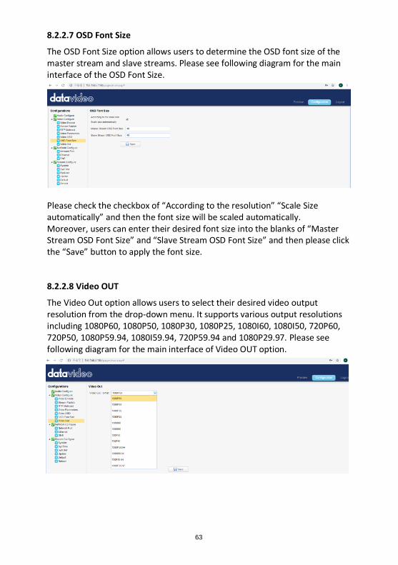
8.2.2.7 OSD Font Size
The OSD Font Size option allows users to determine the OSD font size of the master stream and slave streams. Please see following diagram for the main interface of the OSD Font Size.
Please check the checkbox of “According to the resolution” “Scale Size automatically” and then the font size will be scaled automatically. Moreover, users can enter their desired font size into the blanks of “Master Stream OSD Font Size” and “Slave Stream OSD Font Size” and then please click the “Save” button to apply the font size.
8.2.2.8 Video OUT
The Video Out option allows users to select their desired video output resolution from the drop-down menu. It supports various output resolutions including 1080P60, 1080P50, 1080P30, 1080P25, 1080I60, 1080I50, 720P60, 720P50, 1080P59.94, 1080I59.94, 720P59.94 and 1080P29.97. Please see following diagram for the main interface of Video OUT option.
64
How to Change the Video Output Resolution Please follow following steps for changing the video output resolution. Step 1. Please select your desired video output resolution from the Video OUT Format drop-down menu. Step 2. Please click the “Save” button and then the video output resolution is set successfully.
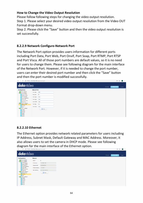
8.2.2.9 Network Configure-Network Port
The Network Port option provides users information for different ports including Port Data, Port Web, Port Onvif, Port Soap, Port RTMP, Port RTSP and Port Visca. All of those port numbers are default values, so it is no need for users to change them. Please see following diagram for the main interface of the Network Port. However, if it is needed to change the port number, users can enter their desired port number and then click the “Save” button and then the port number is modified successfully.
8.2.2.10 Ethernet
The Ethernet option provides network related parameters for users including IP Address, Subnet Mask, Default Gateway and MAC Address. Moreover, it also allows users to set the camera in DHCP mode. Please see following diagram for the main interface of the Ethernet option.
65
How to Set the Camera in DHCP Mode
Please follow following steps for setting the camera in DHCP mode. Step 1. Please check the checkbox of DHCP. Step 2. Please click the “Save” button.
Step 3. Please click the Reboot option and then click the Reboot
button . After that, the camera will be set in DHCP mode successfully. Note: If the camera is set in DHCP mode, The IP Address, Subnet Mask, Default Gateway can not be modified by users. If the DHCP checkbox is not checked and the camera is set in Static IP mode, the IP Address, Subnet Mask and Default Gateway can be modified by users. After the desired parameters are entered, please click the “Save” button and then the Ethernet setting is completed successfully.
8.2.2.11 DNS
The DNS option provides users DNS information including Preferred DNS Server and Alternative DNS Server. The default value is 8.8.8.8 Please see following diagram for the main interface of the DNS option.
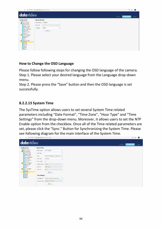
8.2.2.12 System Configure-System Attribute
The SystAttr option allows users to change the Device Name and the OSD language of the camera. Users can select their desired OSD languages including Traditional Chinese, Simplified Chinese and English from the drop-down menu. Please see following diagram for the main interface of the SystAttr option.
66
How to Change the OSD Language
Please follow following steps for changing the OSD language of the camera. Step 1. Please select your desired language from the Language drop-down menu. Step 2. Please press the “Save” button and then the OSD language is set successfully.
8.2.2.13 System Time
The SysTime option allows users to set several System Time related parameters including “Date Format”, “Time Zone”, “Hour Type” and “Time Settings” from the drop-down menu. Moreover, it allows users to set the NTP Enable option from the checkbox. Once all of the Time related parameters are set, please click the “Sync.” Button for Synchronizing the System Time. Please see following diagram for the main interface of the System Time.
67
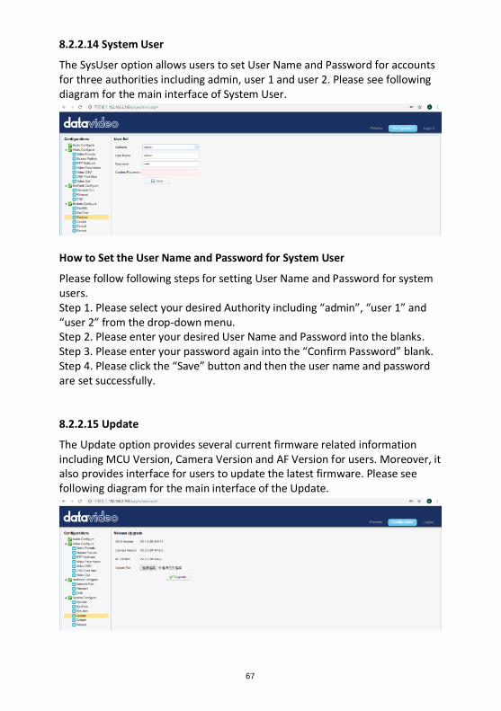
8.2.2.14 System User
The SysUser option allows users to set User Name and Password for accounts for three authorities including admin, user 1 and user 2. Please see following diagram for the main interface of System User.
How to Set the User Name and Password for System User
Please follow following steps for setting User Name and Password for system users. Step 1. Please select your desired Authority including “admin”, “user 1” and “user 2” from the drop-down menu. Step 2. Please enter your desired User Name and Password into the blanks. Step 3. Please enter your password again into the “Confirm Password” blank. Step 4. Please click the “Save” button and then the user name and password are set successfully.
8.2.2.15 Update
The Update option provides several current firmware related information including MCU Version, Camera Version and AF Version for users. Moreover, it also provides interface for users to update the latest firmware. Please see following diagram for the main interface of the Update.
68
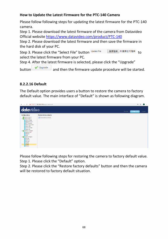
How to Update the Latest Firmware for the PTC-140 Camera
Please follow following steps for updating the latest firmware for the PTC-140 camera. Step 1. Please download the latest firmware of the camera from Datavideo Official website https://www.datavideo.com/product/PTC-140 Step 2. Please download the latest firmware and then save the firmware in the hard disk of your PC.
Step 3. Please click the “Select File” button to select the latest firmware from your PC. Step 4. After the latest firmware is selected, please click the “Upgrade”
button and then the firmware update procedure will be started.
8.2.2.16 Default
The Default option provides users a button to restore the camera to factory default value. The main interface of “Default” is shown as following diagram.
Please follow following steps for restoring the camera to factory default value. Step 1. Please click the “Default” option. Step 2. Please click the “Restore factory defaults” button and then the camera will be restored to factory default situation.
69
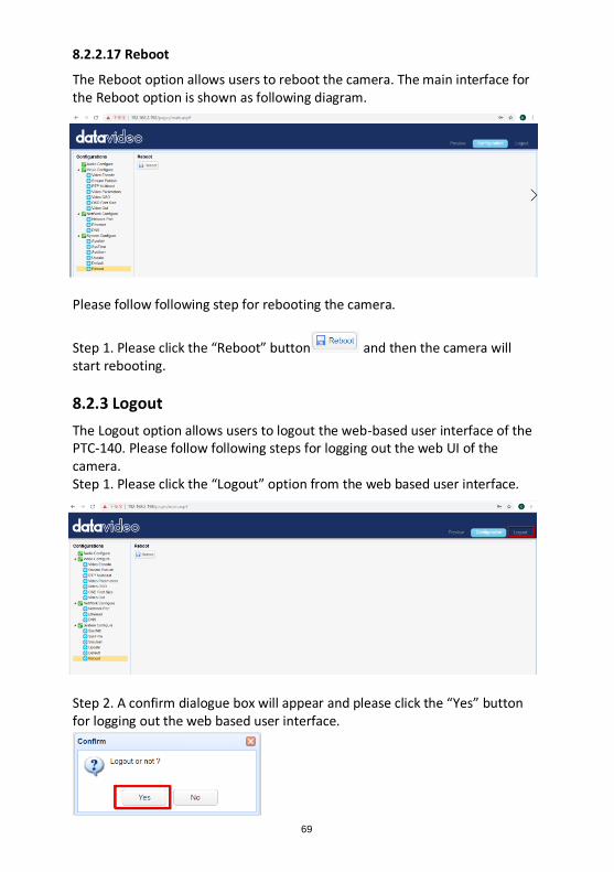
8.2.2.17 Reboot
The Reboot option allows users to reboot the camera. The main interface for the Reboot option is shown as following diagram.
Please follow following step for rebooting the camera.
Step 1. Please click the “Reboot” button and then the camera will start rebooting.
8.2.3 Logout
The Logout option allows users to logout the web-based user interface of the PTC-140. Please follow following steps for logging out the web UI of the camera. Step 1. Please click the “Logout” option from the web based user interface.
Step 2. A confirm dialogue box will appear and please click the “Yes” button for logging out the web based user interface.
70
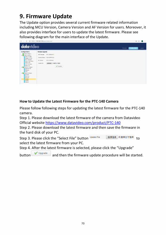
9. Firmware Update The Update option provides several current firmware related information including MCU Version, Camera Version and AF Version for users. Moreover, it also provides interface for users to update the latest firmware. Please see following diagram for the main interface of the Update.
How to Update the Latest Firmware for the PTC-140 Camera
Please follow following steps for updating the latest firmware for the PTC-140 camera. Step 1. Please download the latest firmware of the camera from Datavideo Official website https://www.datavideo.com/product/PTC-140 Step 2. Please download the latest firmware and then save the firmware in the hard disk of your PC.
Step 3. Please click the “Select File” button to select the latest firmware from your PC. Step 4. After the latest firmware is selected, please click the “Upgrade”
button and then the firmware update procedure will be started.
71
10. Frequently-Asked Questions This section describes problems that you may encounter while using the PTC-140. If you have questions, please refer to related sections and follow all the suggested solutions. If problem still exists, please contact your distributor or the service center.
No Problems Solutions
1. What are the
important
points for
product
maintenance?
1. If the camera will not be used for a long time, please unplug the 12V DC power plug. Moreover, please remove the AC power adapter from the AC outlet. 2. Please use soft cloth or tissue to wipe the dust from the case of the camera. 3. If the lens of the camera is washed, please wipe it by a soft and dry cloth. Please use neutral detergent rather than strong or corrosive detergent to wipe the camera to prevent the camera lens from damaging.
2. Why there is
no output
video?
1. Please check that whether the power adapter and power plug are connected correctly. Moreover, please check whether the power LED indicator is lighting up. 2. Please check whether the device is self-checked normally if the power is turned off and then restarted again. 3. Please check whether the cable connection between the camera and the external connected monitor is connected correctly.
72
3. Sometimes
there is no
image?
1. Please check whether the cable connection
between the camera and the external connected
monitor is connected correctly.
4. Image jittering
is happened
when the
camera lens is
zooming.
1. Please check whether the camera is well-mounted. 2. Whether there is a vibrating machine or object that is around the camera.
5. The remote
controller can
not be used.
1. Please check whether the remote controller can be used if the IR address is set to 1. (If the camera is restored to factory default value and then the IR address of the remote controller will be reset to 1). 2. Please check whether the battery of the remote controller is well-installed and whether the battery power is enough or not. 3. Please check whether the working mode of the device is normal or not. 4. Please check whether the OSD menu is closed, the remote controller can be used only when the OSD menu is closed. If the output video is shown on the web-based user interface, the OSD menu will not be shown. If the OSD menu is shown and there is no action for about 30 seconds, the OSD menu will be closed automatically.
73
6. The camera
can not be
controlled by
the serial port.
1. Please check whether the control cable is the standard control cable that is provided by our company. 2. Please check whether the protocol, baud rate and address of the device that is connected are consistent to the protocol, baud rate and address of the camera. 3. Please check whether the control cable is connected correctly or not. 4. Please check whether the working mode of the device is normal or not.
7. The web-
based user
interface can
not be logged
in.
1. Please check whether the output video of the camera can be shown on the external connected monitor correctly or not. 2. Please check whether the Ethernet cable is connected correctly or not (If the yellow LED indicator on the rear panel of the camera is flickering, it means that the Ethernet cable is connected correctly.) 3. Please check that whether the network segment is added for your PC’s network setting and please confirm that whether this network segment is consistent to the camera’s IP address. 4. Please click “Type here to search” from your PC and then please enter CMD command. After that, please click “Enter” to open the DOS command window. Finally, please enter ping 192.168.5.163 to confirm that the network is successfully connected.
74
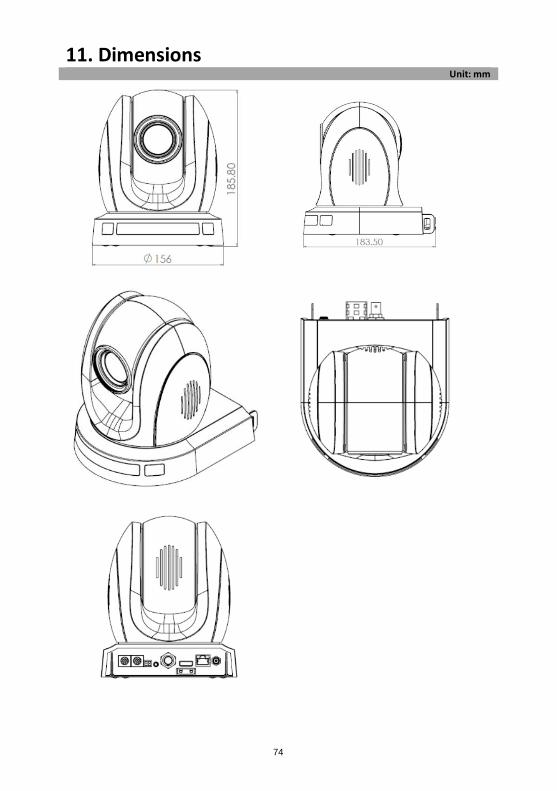
11. Dimensions Unit: mm
75
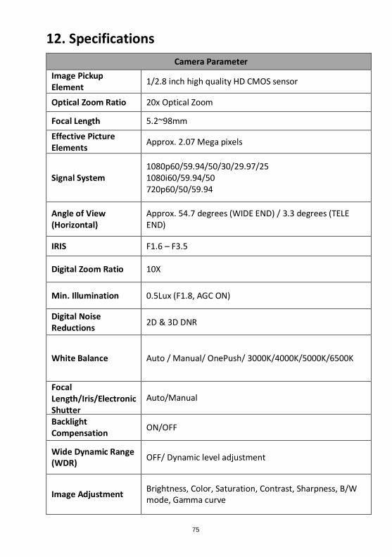
12. Specifications
Camera Parameter
Image Pickup Element
1/2.8 inch high quality HD CMOS sensor
Optical Zoom Ratio 20x Optical Zoom
Focal Length 5.2~98mm
Effective Picture Elements
Approx. 2.07 Mega pixels
Signal System 1080p60/59.94/50/30/29.97/25 1080i60/59.94/50 720p60/50/59.94
Angle of View (Horizontal)
Approx. 54.7 degrees (WIDE END) / 3.3 degrees (TELE END)
IRIS F1.6 – F3.5
Digital Zoom Ratio 10X
Min. Illumination 0.5Lux (F1.8, AGC ON)
Digital Noise Reductions
2D & 3D DNR
White Balance Auto / Manual/ OnePush/ 3000K/4000K/5000K/6500K
Focal Length/Iris/Electronic Shutter
Auto/Manual
Backlight Compensation
ON/OFF
Wide Dynamic Range (WDR)
OFF/ Dynamic level adjustment
Image Adjustment Brightness, Color, Saturation, Contrast, Sharpness, B/W mode, Gamma curve
76
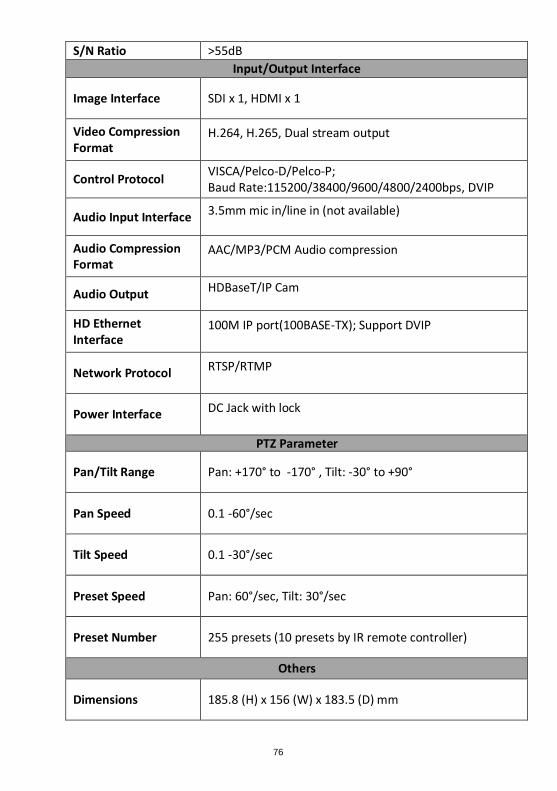
S/N Ratio >55dB
Input/Output Interface
Image Interface SDI x 1, HDMI x 1
Video Compression Format
H.264, H.265, Dual stream output
Control Protocol VISCA/Pelco-D/Pelco-P; Baud Rate:115200/38400/9600/4800/2400bps, DVIP
Audio Input Interface 3.5mm mic in/line in (not available)
Audio Compression Format
AAC/MP3/PCM Audio compression
Audio Output HDBaseT/IP Cam
HD Ethernet Interface
100M IP port(100BASE-TX); Support DVIP
Network Protocol RTSP/RTMP
Power Interface DC Jack with lock
PTZ Parameter
Pan/Tilt Range Pan: +170° to -170° , Tilt: -30° to +90°
Pan Speed 0.1 -60°/sec
Tilt Speed 0.1 -30°/sec
Preset Speed Pan: 60°/sec, Tilt: 30°/sec
Preset Number 255 presets (10 presets by IR remote controller)
Others
Dimensions 185.8 (H) x 156 (W) x 183.5 (D) mm
77
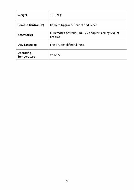
Weight 1.592Kg
Remote Control (IP) Remote Upgrade, Reboot and Reset
Accessories IR Remote Controller, DC 12V adaptor, Ceiling Mount Bracket
OSD Language English, Simplified Chinese
Operating Temperature
0~40 °C

78
Note

79
Note
https://www.datavideo.com/product/PTC-140
Jun.-06 2019
Ver:E1


![PowerPoint 프레젠테이션 - PEOPLUSpplus.co.kr/wp-content/uploads/2017/01/PEOPLUS-Business... · 2017-01-02 · PTC Creo PDM/PLM PTC Windchill PTC Creo [3D CAD] PTC Creo는제품개발프로세스를자동화하여제품의품질을강화하고제품출시기간을](https://img.pdfslide.us/doc/110x75/5ea311508bf7ce2f923a9163/powerpoint-eoe-2017-01-02-ptc-creo-pdmplm-ptc-windchill-ptc.jpg)