Embed Size (px)
Citation preview
Pt
J
a
b
c
d
a
ARRAA
KPFOM
1
ecatmcs
A
C
O
smt
(
0d
Electrochimica Acta 56 (2011) 8509– 8518
Contents lists available at ScienceDirect
Electrochimica Acta
jou rn al hom epa ge: www.elsev ier .com/ locate /e lec tac ta
t–Ru nanoparticles supported on functionalized carbon as electrocatalysts forhe methanol oxidation
.R.C. Salgadoa,∗, J.C.S. Fernandesa, A.M. Botelho do Regob, A.M. Ferrariab, R.G. Duartea,c, M.G.S. Ferreiraa,d
ICEMS, IST, TULisbon, 1049-001 Lisboa, PortugalCQFM and IN, IST, TULisbon, 1049-001 Lisboa, PortugalInstituto Politécnico de Setubal, ESTBarreiro, 2839-001 Barreiro, PortugalCICECO, Universidade de Aveiro, 3810-193 Aveiro, Portugal
r t i c l e i n f o
rticle history:eceived 19 May 2011eceived in revised form 11 July 2011ccepted 11 July 2011vailable online 21 July 2011
eywords:
a b s t r a c t
Platinum–ruthenium alloy electrocatalysts, for methanol oxidation reaction, were prepared on carbonsthermally treated in helium atmosphere or chemically functionalized in H2O2, or in HNO3 + H2SO4 or inHNO3 solutions. The functionalized carbon that is produced using acid solutions contains more surfaceoxygenated functional groups than carbon treated with H2O2 solution or HeTT. The XRD/HR-TEM analysishave showed the existence of a higher alloying degree for Pt–Ru electrocatalysts supported on func-tionalized carbon, which present superior electrocatalytic performance, assessed by cyclic voltammetry,
t–Ru electrocatalystunctionalized carbonxygenated groupsethanol oxidation
chronoamperometry and electrochemical impedance spectroscopy, as compared to electrocatalysts onunfunctionalized carbon. It also was found that Pt–Ru alloy electrocatalysts on functionalized carbonimprove the reaction rate compared to Pt–Ru on carbons treated with H2O2 solution and thermally. Amechanism is discussed, where oxygenated groups generated from acid functionalization of carbon andadsorbed on Pt–Ru electrocatalysts are considered to enhance the electrocatalytic activity of the methanoloxidation reaction.
. Introduction
A direct methanol fuel cell (DMFC) based on a polymerlectrolyte membrane is attractive for transport and portable appli-ations [1,2]. The fuel is cheap, widely available and can be handlednd distributed easily. It could be directly supplied to the anode,hen, the hydrogen ions (protons) migrate through the electrolyte
embrane to the cathode, electrons move through an external cir-uit, and thus, the oxygen reduction occurs at the cathode [1,3]. Theteps and total reaction are:
node : CH3OH(l) + H2O(aq) → CO2(g) + 6H+ + 6e− (1)
athode : (3/2)O2(g) + 6H+ + 6e− → 3H2O(l) (2)
verallreaction : CH3OH(l) + (3/2)O2(g) → CO2(g) + 2H2O(l) (3)
However, several problems still prohibit their practical uses,
uch as [2]: (i) the contamination of the cathode by migration ofethanol through the electrolyte membrane, (ii) the high cost, (iii)he low electrocatalytic activity and the durability of the electro-
∗ Corresponding author. Tel.: +351 218 417 996; fax: +351 218 419 771.E-mail addresses: jrc [email protected], [email protected]
J.R.C. Salgado).
013-4686/$ – see front matter © 2011 Elsevier Ltd. All rights reserved.oi:10.1016/j.electacta.2011.07.039
© 2011 Elsevier Ltd. All rights reserved.
catalysts impregnated and lastly (iv) the poisoning of the platinumelectrocatalysts that are used for methanol oxidation in the anodicelectrode.
Concerning the last point, the use of platinum–ruthenium alloyselectrocatalysts can increase the current densities and to avoid theformation of carbon monoxide (CO) on the electrocatalysts (poi-soning) [3]. Ru forms oxygenated species at lower potential thanPt and its presence in the electrocatalysts promotes oxidation ofCO into CO2 by the bifunctional mechanism and/or a “ligand effect”[4–8].
To effectively use these metals as electrocatalysts, they haveto be well dispersed in small particles on a carbon support [9].Although carbon is an excellent electronic conductor it is a verypoor proton conductor. This is mainly because carbon is hydropho-bic. However, on the carbon surface some hydrophilic groups likecarbonyl, carboxyl, phenolic, quinone and lactone groups can beinserted [10]. These groups are normally introduced in the carbonby various oxidation treatments (e.g., nitric acid, hydrogen perox-ide, hypochlorite and others) [10–12].
Several material supports, such as black carbon, meso-
porous carbon, carbon nanofibers and carbon nanotubes havebeen researched and used for the manufacture of commerciallyavailable metal electrocatalysts, as reported in the litera-ture [9,13–22]. However, the nature of the carbon structures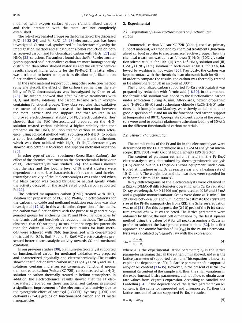
8 himica
mae
PiiaHldrwf
(b[Hcttisspeaws[
eotdtttP
stitgtotonso
oasstsatatcn
510 J.R.C. Salgado et al. / Electroc
odified with oxygen surface groups (functionalized carbon)nd their interaction with the metal are not completelystablished.
The role of oxygenated groups on the formation of the dispersedt/C [16,22–24] and Pt–Ru/C [25–28] electrocatalysts has beennvestigated. Carmo et al. synthesized Pt–Ru electrocatalysts by thempregnation method and subsequent alcohol reduction on boths received carbon and functionalized carbon with H2O2 [27] andNO3 [28] solutions. The authors found that the Pt–Ru electrocata-
ysts supported on functionalized carbon are more homogeneouslyistributed than other studied materials and the electrochemicalesults showed higher activity for the Pt–Ru/C. This latter effectas attributed to better nanoparticles distribution/utilization on
unctionalized carbon.In the same material support but using other reduction method
ethylene glycol), the effect of the carbon treatment on the sta-ility of Pt/C electrocatalysts was investigated by Chen et al.23]. The authors showed that after oxidative treatments with2O2 and HNO3 solutions, the carbon became rich in oxygen-ontaining functional groups. They observed also that oxidativereatments of the carbon increased the interaction betweenhe metal particle and the support, and that resulted in anmproved electrochemical stability of Pt/C electrocatalysts. Theyhowed that the Pt/C electrocatalyst prepared on the H2O2olution treated carbon exhibited a higher stability than thatrepared on the HNO3 solution treated carbon. In other refer-nce, using colloidal method with a solution of NaHSO3 to obtain
colourless soluble intermediate of platinum and ruthenium,hich was then oxidized with H2O2, Pt–Ru/C electrocatalysts
howed also better CO tolerance and superior methanol oxidation25].
In other type of carbon specimen (Korea Black Carbon), theffect of the chemical treatment on the electrochemical behaviourf Pt/C electrocatalysts was studied [24]. The authors showedhat the size and the loading level of Pt metal clusters wereependent on the surface characteristics of the carbon and the elec-rocatalytic activity of the Pt electrocatalysts was enhanced whenhe black carbon was treated by basic or neutral agents, whilehe activity decayed for the acid-treated black carbon supportedt [29].
The ordered mesoporous carbon (OMC) treated with HNO3olution for preparation of Pt/C and Pt–Ru/C electrocatalysts forhe carbon monoxide and methanol oxidation reactions was alsonvestigated [17,18]. In this work, before deposition of the metals,he carbon was functionalized with the purpose to generate oxy-enated groups for anchoring the Pt and Pt–Ru nanoparticles byhe formic acid and borohydride reduction methods. The authorsbserved that CO stripping occurs at more negative potentialshan for Vulcan XC-72R, and the best results for both meth-ds were achieved with OMC functionalized with concentrateditric acid for 0.5 h. Both Pt and Pt–Ru/OMC electrocatalysts pre-ented better electrocatalytic activity towards CO and methanolxidation.
In our previous studies [30], platinum electrocatalyst supportedn functionalized carbon for methanol oxidation was preparednd characterized physically and electrochemically. The resultshowed that functionalized carbon using H2SO4 + HNO3 and HNO3olutions contains more surface oxygenated functional groupshan untreated carbon (Vulcan XC-72R), carbon treated with H2O2olution or carbon thermally treated in helium atmosphere. Inddition, the electrochemical results showed that the Pt elec-rocatalyst prepared on those functionalized carbons presented
significant improvement of the electrocatalytic activity due tohe synergistic effect of carboxyl (–COOH), hydroxyl (–OH) andarbonyl ( C O) groups on functionalized carbon and Pt metalanoparticles.
Acta 56 (2011) 8509– 8518
2. Experimental
2.1. Preparation of Pt–Ru electrocatalysts on functionalizedcarbon
Commercial carbon Vulcan XC-72R (Cabot), used as primarysupport material, was modified by chemical treatments (function-alized carbon) in order to create surface reactive groups. Then, thechemical treatment was done as follows: (i) H2O2 (30%, v/v) solu-tion stirred at 60 ◦C for 10 h; (ii) 3 mol L−1 HNO3 solution and (iii)H2SO4 + HNO3 (1:1) solution in both cases at 80 ◦C for 12 h, fol-lowed by washing in hot water [30]. Previously, the carbon waskept in contact with the chemicals in an ultrasonic bath for 40 min.In order to compare the results, the carbon was thermally treatedin He atmosphere for 3 h in an oven at 300 ◦C.
The functionalized carbon supported Pt–Ru electrocatalyst wasprepared by reduction with formic acid [18,30]. In this method,the formic acid solution was added to the functionalized carbonunder sonication during 40 min. Afterwards, hexachloroplatinicacid (H2PtCl6·6H2O) and ruthenium chloride (RuCI3·3H2O) solu-tions, both from Johnson Matthey, were slowly added to obtain agood dispersion of Pt and Ru on the functionalized carbon supportat temperature of 80 ◦C. Appropriate concentrations of the precur-sors were used to obtain a platinum–ruthenium loading of 30 wt.%on the different functionalized carbon materials.
2.2. Physical characterization
The atomic ratios of the Pt and Ru in the electrocatalysts weredetermined by the EDX technique in a FEG-SEM analytical micro-scope: JEOL 7001F with Oxford light elements EDS detector.
The content of platinum–ruthenium (metal) in the Pt–Ru/Celectrocatalysts was determined by thermogravimetric analysis(TGA) carried out in a LabSys-SETARAM equipment, under con-trolled atmosphere using O2 as reactive gas and a heating rate of10 ◦C min−1. The weight loss and the heat flow were recorded foreach sample from 25 to 1000 ◦C.
X-ray diffractograms of the electrocatalysts were obtained ina Rigaku D/MAX-B diffractometer operating with Cu K� radiation(X-ray wavelength, � = 0.15406 nm) generated at 40 kV and 35 mAand a graphite monochromator. Scans were done at 3◦ min−1 for2� values between 30◦ and 90◦. In order to estimate the crystallitesize of the Pt–Ru nanoparticles from XRD, the Scherrer’s equationwas used [31]. For this purpose, the (2 2 0) peak of the Pt fcc struc-ture around 2� = 67.7◦ was selected. The lattice parameters wereobtained by fitting the unit cell dimensions by the least squaresmethod using the values of � for all peaks assuming a Gaussianprofile to subtract the background contributions [32]. In a firstapproach, the atomic fraction of Ru (xRu) in the Pt–Ru electrocata-lysts was calculated by Vegard’s law with the expression:
xRu = a − ao
ac − ao(4)
where a is the experimental lattice parameter; ac is the latticeparameter assuming that all the ruthenium is alloyed, and ao is thelattice parameter of supported platinum. This equation is known toexplain the dependence of Pt–Ru lattice parameter of unsupportedalloy on Ru content [33–35]. However, in the present case the lownominal Ru content of the sample and, thus, the small variations inthe experimental lattice parameters, did not allow to obtain accu-rate values from Vegard’s expression. According to Antolini andCardellini [34], if the dependence of the lattice parameter on Ru
content is the same for supported and unsupported Pt, then thelattice constant of carbon supported Pt–Ru, a, results:a = ac − kxRu (5)

J.R.C. Salgado et al. / Electrochimica Acta 56 (2011) 8509– 8518 8511
Table 1Structural characteristics, nominal atomic composition (EDX), analysis thermogravimetric (TGA), crystallite size (d), lattice parameter (a), atomic fraction in the alloy (xRu),degree of alloying (RuAL) and electroactive area (Scv) of Pt–Ru/C alloy electrocatalysts.
Treatment Ru (at.%) TGA (wt.%) d (nm) a (A) xRu (%) RuAL (%) Scv (m2 g−1)
HeTT 14 31 3.0 3.9187 ± 0.00307 3.5 23 34H2O2 13 31 3.3 3.9177 ± 0.00268 4.4 30 30
wid
ems3bHurcuh
uAaptcp4
2
ighp
desa(
oawpt
gs0uadHt
sw
H2SO4 + HNO3 10 28 4.3
HNO3 12 28 4.5
here ac is the lattice parameter of pure carbon supported plat-num, taken as 3.9231 A, and k = 0.124 A is a constant, obtained fromata related to unsupported alloys [34].
Nanoparticle size and metal dispersion images of Pt–Ru/Clectrocatalysts were obtained using a transmission electronicroscope (TEM) Hitachi H8100. For such measurements, the
amples were immersed in water and ultrasonically dispersed for min. Then a drop of this suspension was deposited on a car-on grid and, after drying, the grid was ready for observation.istograms of particles size supported on carbon were obtainedsing about 400 particles, excluding the agglomeration region. Highesolution TEM (HR-TEM) experiments were carried out in the Syn-hrotron Light Brazilian Laboratory (LNLS, Campinas, SP, Brazil)sing a microscope JEOL, JEM 3010, URP, operating at 300 kV andaving a resolution of 0.17 nm.
X-ray photoelectron spectra (XPS) were acquired using thenmonochromatic Al K� radiation (h� = 1486.6 eV) from a Kratosnalytical XSAM800 equipment. Carbon powdered samples as wells Pt–Ru/C electrocatalysts were mounted on the sample holder byressing the powder against a double-faced tape. For details abouthe operation parameters, data treatment and charge accumulationorrection see [30]. The sensitivity factors used for quantificationurposes were: C 1s: 0.25; O 1s: 0.66; N 1s: 0.42; S 2p: 0.54; Pt 4f:.4 and Ru 3p3/2: 1.8.
.3. Electrochemical characterization
A conventional one-compartment glass cell with a Luggin cap-llary was used in the electrochemical experiments. A large arearaphite bar served as the counter electrode and a reversibleydrogen electrode (RHE) was used as the reference electrode. Allotentials in the text are referenced to this electrode.
The working electrodes were composed by the electrocatalystseposited as a thin layer over a pyrolitic graphite disk (5 mm diam-ter, 0.196 cm2 geometric area) for conventional electrochemicaltudies. An aqueous suspension of 2.0 mg of the metal/C electrocat-lyst was prepared by ultrasonically dispersing in 15 �L of Nafion®
5 wt.%, Aldrich) and 500 �L of pure water (Millipore).An aliquot of the dispersed suspension was pipetted on the top
f the graphite disk and dried. All the experiments were conductedt room temperature (22 ± 1 ◦C). After preparation, the electrodeas immersed into deaerated 0.5 mol L−1 H2SO4 (base electrolyte),repared from Panreac reagent and water purified in a Milli-Q sys-em. The electrolyte was saturated with pure nitrogen (Air Liquide).
To characterize the Pt–Ru/C electrocatalysts, cyclic voltammo-rams (CV) were recorded in the base (supporting) electrolyteolution between 0.05 and 0.80 V vs. RHE at a scan rate of.05 V s−1. In the electrochemical experiments, the current val-es were normalized (specific activity) through division by therea of underpotential deposited copper (CuUPD) [36–39]. This wasone using an aqueous electrolyte (0.5 mol L−1 H2SO4; 0.5 mol L−1
2SO4 + 0.001 mol L−1 CuSO4) solution. Prior to each measurement,
he electrolytes were purged with nitrogen.The amount of platinum (mass activity) was calculated con-idering the mass of the Pt–Ru electrocatalyst present in theorking electrode and the percentage of Pt (Table 1). Electrochem-
3.9153 ± 0.00075 6.3 60 273.9165 ± 0.00057 5.3 41 26
ical studies were carried out using a Radiometer-Voltalab PGZ 100apparatus.
Cyclic voltammograms in 0.5 mol L−1 methanol (Flukareagent) + 0.5 mol L−1 H2SO4 solution to evaluate the perfor-mance of the electrocatalysts for the oxidation of methanol werealso obtained.
Soon after, in a new solution with the same composition,current–time curves (chronoamperometry) were recorded at0.60 V vs. RHE, in order to evaluate the performance of the elec-trocatalysts for the methanol oxidation.
Electrochemical impedance spectroscopy (EIS) measurementswere carried out immediately after chronoamperometry by sweep-ing the frequency in the range of 10 kHz to 0.1 Hz. dc electrodepotential was kept at different values in the range of 0.30–0.65 Vvs. RHE and a 0.01 V ac signal was applied for the measurements.Spectra were treated with the Z-view Software (Scribner Asso-ciates, Inc.), using the adequate equivalent electric circuits. TheEIS experiments were carried out using a Gamry, Reference 600Potentiostat/Galvanostat/ZRA with a PC4 Controller Board.
3. Results and discussion
3.1. Characterization of the electrocatalysts
The EDX compositions of Pt–Ru electrocatalysts on supportfunctionalized carbon are shown in Table 1. It can be seen that theaverage EDX compositions of electrocatalysts are near the nominalvalue (Pt:Ru, 85:15). In a previous paper [35] it was mentionedthat it was not possible to anchor more than 25 at.% of Ru onPt–Ru-supported materials using formic acid as reducing agent.One possible explanation for this is the formation of a complexbetween Ru and formic acid which partially prevents its anchoringon the carbon support.
TGA results in O2 (reactive gas) controlled atmosphere areshown in Table 1. After thermal treatment at 1000 ◦C the carbonPt–Ru samples keep a constant mass, around 28–31% of the originalmaterials that corresponds to the metal load of the electrocatalysts.These values were used in the calculation of mass for each electrode.
X-ray diffraction spectra for the Pt–Ru electrocatalysts preparedon the carbon supports treated thermally and chemically modifiedare shown in Fig. 1. It is noticeable that the crystalline structure ofthe metal in the nanoparticles is apparent and all the XRD patternsclearly show the five main characteristic peaks of the face-centredcubic (fcc) crystalline Pt, namely at 39.7◦, 46.3◦, 67.7◦, 81.5◦ and85.9◦ assigned to planes (1 1 1), (2 0 0), (2 2 0), (3 1 1) and (2 2 2),respectively.
Diffraction peaks of the Pt–Ru electrocatalysts on functional-ized carbon treated with H2SO4 + HNO3 and HNO3 solutions aresharp indicating large crystallite size. The diffraction peak of thePt (2 2 0) plane was selected to calculate the mean crystallite sizesfor the electrocatalysts and the Scherrer equation was applied. Thecrystallite sizes obtained are given in Table 1. It can be observed
that the size depends on chemical treatment of the carbon sup-port. The mean crystallite size for the Pt–Ru/C electrocatalyst variesfrom 3.00 to 4.49 nm. It can be observed that the crystallite sizefor the Pt–Ru electrocatalysts on carbon heat treated under helium
8512 J.R.C. Salgado et al. / Electrochimica
FH
aPapfb
ttPtiibp
ss0ltvPiwP
at(lte
R
chfaatp
pl
ig. 1. XRD diffractograms of Pt–Ru electrocatalysts on carbon thermally treated ine (HeTT) and on different functionalized carbon.
tmosphere or treated with hydrogen peroxide is smaller than fort–Ru on functionalized carbon treated with mixed H2SO4 + HNO3nd HNO3 solutions, as shown in Table 1. These results agree withrevious values found in the literature [7,16,40–42], namely thoseor reduction of the platinum–ruthenium electrocatalysts on car-on with acid formic solution [40,41].
The five diffraction peaks in the Pt–Ru electrocatalyst on func-ionalized carbon (H2SO4 + HNO3 and HNO3) are modestly shiftedo higher angles with respect to the corresponding peaks for thet–Ru on H2O2 and HeTT carbon (Fig. 1, inset), indicating a con-raction of the lattice and Pt–Ru alloy formation due the possiblencorporation of Ru atoms. No peaks for metallic ruthenium and/orts oxides were observed, but their presence cannot be discardedecause they may be present in a small amount or even in an amor-hous form.
The lattice parameter values of Pt–Ru/C electrocatalysts are alsoummarized in Table 1. In all cases, the lattice parameters aremaller than those found for pure Pt (3.9231 A), JCPDS card no.4-0802, which indicates the presence of Ru substituting Pt in the
attice, leading to a smaller value and indicating the formation ofhe Pt–Ru alloy in the electrocatalyst [34,35,43–46]. Moreover, thealues for Pt–Ru on functionalized carbon were smaller than fort–Ru/C (HeTT and H2O2) and show a tendency to decrease withncreasing of the crystallite size, as show in Table 1. This behaviour
as already seen for other alloys supported on carbon as Pt–Co,t–Cr and Pt–Ni electrocatalysts [17,47–49].
From the values of lattice parameters obtained by XRD, andccording to Eq. (5) proposed by Antolini et al., the atomic frac-ion of Ru in the electrocatalyst supported on carbon was calculatedTable 1). Moreover, the percentage of alloyed Ru (RuAL), was calcu-ated from the nominal Ru content of the sample (Ru/Pt)nom andhe atomic fraction in the alloy (xRu), according to the followingquation [34]:
uAL = xRu
(1 − xRu)(Ru/Pt)nom(6)
According to Table 1, the unfunctionalized carbon Pt–Ru electro-atalysts show a higher nominal atomic ruthenium content but onlyave in average about 25% of ruthenium alloyed with Pt, while for
unctionalized carbon supported electrocatalysts (H2SO4 + HNO3nd HNO3) a slight lower nominal Ru content, was found but with
higher alloyed percentage (ca. 50% in average). Therefore, not allhe ruthenium present in the Pt–Ru electrocatalysts is alloyed with
latinum, as shown in Table 1.Fig. 2 shows TEM images of the nanoparticles oflatinum–ruthenium supported on HeTT treated carbon (Fig. 2,
eft) and HNO3 functionalized carbon (Fig. 2, right). The corre-
Acta 56 (2011) 8509– 8518
sponding particle size distribution histograms are also reported inFig. 2 – below. As can be seen, TEM images present in both cases ahomogeneous dispersion of Pt–Ru alloy on the carbon support. It ispossible to observe in Fig. 2 that some areas of the electrocatalystssupported on carbon present agglomeration due to approximationof the smaller nanoparticles. The presence of functional groupsderived from chemical oxidation treatment likely act as reactivesite for the metal particles and would help in anchoring theseparticles on its surface [9].
High resolution TEM micrograph, obtained with a magnificationof 800,000 for Pt–Ru on functionalized carbon treated with HNO3solution also is represented in Fig. 2. It is possible to see an image ofa single particle where the crystalline (1 1 1) plane of the sphericalPt–Ru is evident [50]. The 0.2143 nm spacing which is attributed tothe Pt–Ru (1 1 1) plane of the fcc lattice is indicated in figure. Com-pared to the nominal Pt (1 1 1) spacing of 0.226 nm (JCPDS 04-0802)[51], the spacing is lower indicating again smaller lattice parameter,consequently, the formation of Pt–Ru/C alloy electrocatalyst [50].This result from HR-TEM analysis for the Pt–Ru/C agrees well withthe XRD results.
Moreover, Pt–Ru electrocatalyst on functionalized carbon(HNO3 solution) shows a particle size distribution broader than thatof Pt–Ru on carbon thermally treated. For the Pt–Ru electrocatalystsprepared on carbon treated with HNO3 solution, 60% of the parti-cles have diameters between 3.5 and 4.5 nm with a mean particlesize of 4.0 nm, while for the Pt–Ru electrocatalysts on HeTT carbon60% of the particles have diameters between 2.5 and 3.5 nm witha mean particle size of 3.1 nm (Fig. 2). Therefore, the particle sizesobtained from the TEM images are compatible with the crystallitesizes calculated from the XRD (2 2 0) peak.
The four Pt–Ru/C electrocatalysts samples were characterizedby XPS. Table 2 displays the peak binding energies, assignment andatomic percentages. XPS C 1s, O 1s, N 1s, S 2p, are very similar tothose described in a preceding paper [30], both from the qualitativeand quantitative point of view.
The most studied XPS region for ruthenium is Ru 3d. However,this region partly overlaps the C 1s region: Ru 3d5/2 presents bind-ing energies ranging from 279 to 285 eV and, since the spin orbitsplitting is 4.15 eV, Ru 3d3/2 has binding energies ranging from∼283 to ∼289 eV fully overlapping the C 1s region. Moreover, whenthe substrate is mainly carbon, as it is the case in this work, the C1s peak is so intense that completely masks even the component3d5/2.
In this work, to study the oxidation state and the relative amountof ruthenium, the Ru 3p3/2 region was chosen. It was found in theliterature that the ruthenium oxides are conductive [52] and, thenthe peaks were fitted with an asymmetrical pseudo-Voigt profile(Gaussian–Lorentzian product). The Excel’s Solver for minimizingthe quadratic differences sum was used [53].
The profile is shown in Fig. 3 just for one of the Pt–Ru/C elec-trocatalysts samples, since it is qualitatively very similar in all thesamples. In all the cases, the maximum was at 462.1 eV. This valueis slightly smaller than the range existing in the literature for theRuO2 oxide (462.7 ± 0.3 eV) [53]. This may be associated to the factthat an intimate mixture with platinum oxide exists changing thebinding energy of Ru 3p. However, the binding energy for Pt2+ 4fkeeps the same value, within the experimental error, obtained inthe absence of ruthenium [30].
Due to the overall low nominal Ru compositions and, in par-ticular, to the small atomic fraction of Ru in the Pt–Ru alloyelectrocatalyst, it was not possible to deconvolute the XPS spec-tra in order to separate the contributions of the metallic Ru and of
ruthenium oxide. Even in the case of RuO2, only a small amount wasobserved in the quantitative analysis by XPS technique. However, itwas possible to plot this RuO2 quantity (Table 2) as a function of thelattice parameter values from XRD data (Table 1), as shown in Fig. 4.
J.R.C. Salgado et al. / Electrochimica Acta 56 (2011) 8509– 8518 8513
Fig. 2. TEM micrograph of Pt–Ru/C: (left) HeTT, (right) HNO3 and (below) higher magnification of Pt–Ru/C, HNO3. Histogram of Pt–Ru particles supported on HeTT and HNO3
functionalized carbon.
Table 2XPS binding energies and atomic percentages in Pt–Ru/C alloy electrocatalysts.
Binding energy (eV) HeTT H2O2 HNO3 + H2SO4 HNO3 Assignment [65,66]
C 1s 1 284.6 ± 0.1 70.1 71.6 65.0 65.9 sp2 and sp3 C–C, C–HC 1s 2 286.2 ± 0.1 11.6 10.5 11.1 10.1 C–OC 1s 3 287.7 ± 0.2 4.4 4.5 4.4 4.7 C OC 1s 4 289.3 ± 0.1 2.9 3.0 3.8 3.6 O–C O
C 1s 5 291.1 ± 0.3 2.4 2.5 2.2 1.9 + �–�* lossO 1s 1 531.3 ± 0.4 2.2 2.5 7.6 5.4 Metal oxide + C OO 1s 2 533.0 ± 0.6 2.5 2.2 2.1 4.5 C–OO 1s 3 536.0 ± 0.1 0.4 H2O
N 1s 1* 399.2 ± 0.2 0.38 0.35 0.30 Amine*
S 2p3/2 163.9 ± 0.2 0.13 0.09 0.12 0.11 S–CS 2p1/2 165.1 ± 0.2 0.07 0.04 0.06 0.06
Pt 4f7/2 1 71.7 ± 0.1 0.85 0.84 0.95 0.84 Pt–Ru [67]Pt 4f5/2 1 75.0 ± 0.1 0.64 0.63 0.71 0.63Pt 4f7/2 2 72.8 ± 0.1 0.75 0.66 0.81 0.68 Pt–O [68]Pt 4f5/2 2 76.1 ± 0.1 0.56 0.49 0.61 0.51 Pt(OH)2 [69]
Ru 3p3/2 462.1 ± 0.1 0.43 0.41 0.24 0.34 RuO2
Percentages Total C 91.4 92.2 86.5 86.2Total O 4.8 4.7 9.7 10.3Total Pt 2.81 2.61 3.08 2.67Total Ru 0.43 0.41 0.24 0.34
Pt:Ru composition 86.6:13.4 86.6:13.5 92.9:7.1 88.6:11.4

8514 J.R.C. Salgado et al. / Electrochimica Acta 56 (2011) 8509– 8518
Fig. 3. C 1s, Pt 4f and Ru 3p3/2 XPS regions for all the carbons studied. For the sake of simpatmosphere (HeTT) are shown. From bottom to top: HeTT, H2O2, H2SO4 + HNO3 and HNO
Fr
IrlcT
3
saFs
Pcpihft
ig. 4. Relation between the lattice parameter obtained from XRD data and the Ruelative amount obtained by XPS.
t is observed that the smaller the lattice parameter the lower is theuthenium oxide quantity present in the Pt–Ru alloy electrocata-ysts on functionalized carbon. In fact, the Pt–Ru on functionalizedarbon presents the larger Pt–Ru alloying degree, as observed inable 1 [14,34,35].
.2. Electrochemical studies of Pt–Ru/C electrocatalysts
Cyclic voltammograms (CV) performed in a single cell with N2aturated base electrolyte, of Pt–Ru on carbon treated under heliumtmosphere (HeTT) and carbon chemically treated are shown inig. 5. Due to preferential dissolution of ruthenium potentials werewept only between 0.05 and 0.8 V vs. RHE [54].
In the potential range 0.05–0.4 V (RHE) of the CV curves for thet–Ru electrocatalysts the hydrogen adsorption/desorption peaksharacteristics of a polycrystalline Pt are shown [30,38]. In theresent work, the current densities were larger compared to plat-
num supported on carbon in our reference [30]. Moreover, theydrogen peaks (Fig. 5) are a slightly more sharper for the Pt–Ru on
unctionalized carbons (H2SO4 + HNO3 and HNO3) than for carbonsreated under helium atmosphere (HeTT) and with H2O2 solution
licity, just the fittings for the peaks from carbon thermally treated under a helium3.
due to some enrichment of Pt character (confirmed by the EDSspectrum) on those Pt–Ru on functionalized carbon.
In the potential range 0.4–0.8 V (RHE), the oxidation of theoxygen-containing surface groups present on carbon after thechemical treatment with acid solutions occur as it was alreadyobserved before [30]. These results imply that the surfaces ofthe functionalized carbon with acid solutions have been activatedwith the oxygen that was introduced into the carbon structure,as observed by Fourier transform infrared spectroscopy and XPSresults [30].
As mentioned above, in the electrochemical experiments thecurrent values for methanol oxidation were normalized to theCuUPD area [36–38]. The method to determine CuUPD electroactiveareas (SCV) is associated to monolayer saturation of copper thatis adsorbed on the Pt–Ru surface in the UPD region, as adopted byGreen and Kucernak [37]. The SCV values are summarized in Table 1.It can be observed that electroactive areas for Pt–Ru electrocata-lysts on carbons treated with HeTT and H2O2 solution are largercompared to those of Pt–Ru on functionalized carbons. As pointedout in the literature, monolayer adsorption of copper on the sur-face of Pt–Ru/C electrocatalysts is a ‘tempting’ assumption, whichmight introduce some error [55]. However, the result presentedhere is expected since the electroactivity area decrease with theparticle sizes increase, as observed by XRD/TEM results. However,the presence of Nafion® that may block the contact of surface ofparticles with the electrolyte cannot be discarded. In spite of thispotential limitation the CuUPD process is suitable and it was foundto be consistent and reproducible for determination of the Pt–Ruelectroactive area under the present conditions [37,39].
The voltammograms for the methanol oxidation on the Pt–Ru/Celectrocatalysts in 0.5 mol L−1 H2SO4 + 0.5 mol L−1 CH3OH solutionat room temperature are shown in Fig. 6 where current densitiesare normalized with respect to (a) mass activity or to (b) specificactivity (per area of CuUPD). The methanol-containing electrolyte
was previously purged with nitrogen in order to avoid oxygencontamination. Again it should be observed that the Pt–Ru/C elec-trocatalysts supported on functionalized carbon (H2SO4 + HNO3and HNO3) showed higher current densities for methanol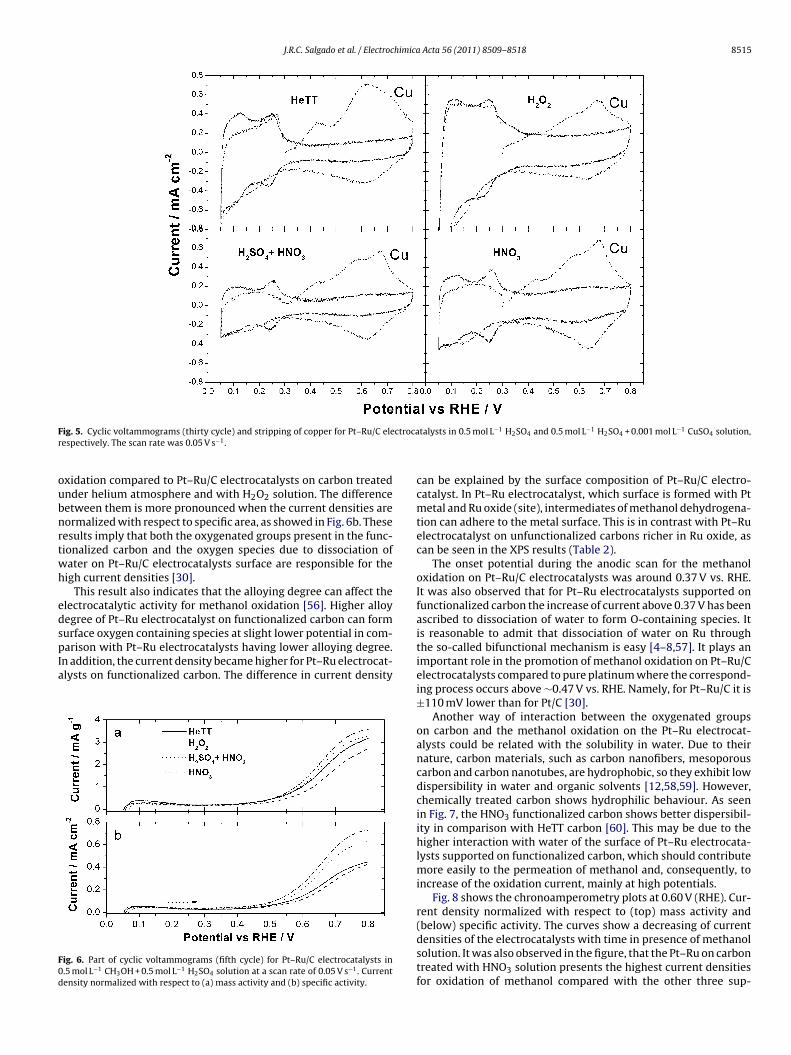
J.R.C. Salgado et al. / Electrochimica Acta 56 (2011) 8509– 8518 8515
F ctrocar
oubnrtwh
edspIa
F0d
ig. 5. Cyclic voltammograms (thirty cycle) and stripping of copper for Pt–Ru/C eleespectively. The scan rate was 0.05 V s−1.
xidation compared to Pt–Ru/C electrocatalysts on carbon treatednder helium atmosphere and with H2O2 solution. The differenceetween them is more pronounced when the current densities areormalized with respect to specific area, as showed in Fig. 6b. Theseesults imply that both the oxygenated groups present in the func-ionalized carbon and the oxygen species due to dissociation ofater on Pt–Ru/C electrocatalysts surface are responsible for theigh current densities [30].
This result also indicates that the alloying degree can affect thelectrocatalytic activity for methanol oxidation [56]. Higher alloyegree of Pt–Ru electrocatalyst on functionalized carbon can formurface oxygen containing species at slight lower potential in com-
arison with Pt–Ru electrocatalysts having lower alloying degree.n addition, the current density became higher for Pt–Ru electrocat-lysts on functionalized carbon. The difference in current density
ig. 6. Part of cyclic voltammograms (fifth cycle) for Pt–Ru/C electrocatalysts in.5 mol L−1 CH3OH + 0.5 mol L−1 H2SO4 solution at a scan rate of 0.05 V s−1. Currentensity normalized with respect to (a) mass activity and (b) specific activity.
talysts in 0.5 mol L−1 H2SO4 and 0.5 mol L−1 H2SO4 + 0.001 mol L−1 CuSO4 solution,
can be explained by the surface composition of Pt–Ru/C electro-catalyst. In Pt–Ru electrocatalyst, which surface is formed with Ptmetal and Ru oxide (site), intermediates of methanol dehydrogena-tion can adhere to the metal surface. This is in contrast with Pt–Ruelectrocatalyst on unfunctionalized carbons richer in Ru oxide, ascan be seen in the XPS results (Table 2).
The onset potential during the anodic scan for the methanoloxidation on Pt–Ru/C electrocatalysts was around 0.37 V vs. RHE.It was also observed that for Pt–Ru electrocatalysts supported onfunctionalized carbon the increase of current above 0.37 V has beenascribed to dissociation of water to form O-containing species. Itis reasonable to admit that dissociation of water on Ru throughthe so-called bifunctional mechanism is easy [4–8,57]. It plays animportant role in the promotion of methanol oxidation on Pt–Ru/Celectrocatalysts compared to pure platinum where the correspond-ing process occurs above ∼0.47 V vs. RHE. Namely, for Pt–Ru/C it is±110 mV lower than for Pt/C [30].
Another way of interaction between the oxygenated groupson carbon and the methanol oxidation on the Pt–Ru electrocat-alysts could be related with the solubility in water. Due to theirnature, carbon materials, such as carbon nanofibers, mesoporouscarbon and carbon nanotubes, are hydrophobic, so they exhibit lowdispersibility in water and organic solvents [12,58,59]. However,chemically treated carbon shows hydrophilic behaviour. As seenin Fig. 7, the HNO3 functionalized carbon shows better dispersibil-ity in comparison with HeTT carbon [60]. This may be due to thehigher interaction with water of the surface of Pt–Ru electrocata-lysts supported on functionalized carbon, which should contributemore easily to the permeation of methanol and, consequently, toincrease of the oxidation current, mainly at high potentials.
Fig. 8 shows the chronoamperometry plots at 0.60 V (RHE). Cur-rent density normalized with respect to (top) mass activity and(below) specific activity. The curves show a decreasing of current
densities of the electrocatalysts with time in presence of methanolsolution. It was also observed in the figure, that the Pt–Ru on carbontreated with HNO3 solution presents the highest current densitiesfor oxidation of methanol compared with the other three sup-
8516 J.R.C. Salgado et al. / Electrochimica
Ft
pww3tPHtdcos
tgcipdaf
FCiH
ig. 7. Dispersibility behaviour of carbon treated with (a) HeTT and (b) HNO3 solu-ion after one day (sonicated for 15 min).
orts. The current densities normalized in terms of mass activityere of 0.7–0.9 mA cm−2 after 30 min. For the curves normalizedith respect to specific activity (below), the current density after
0 min for Pt–Ru/C electrocatalysts functionalized with HNO3 solu-ion reached a value of 0.18 mA cm−2 which is higher than those fort–Ru on carbon treated H2SO4 + HNO3 solution (0.15 mA cm−2),eTT (0.12 mA cm−2) and in H2O2 solution (0.10 mA cm−2). Then,
he platinum–ruthenium on carbon that presented higher alloyingegree and larger amount of oxygenated species on functionalizedarbon (Pt–Ru/C, HNO3 solution) is better than Pt–Ru supportedn carbon without or few oxygenated groups (HeTT and H2O2olution).
Electrochemical impedance spectra (EIS) for the Pt–Ru elec-rocatalysts on functionalized carbon at different potentials areiven in Fig. 9. The EIS studies confirm the trend observed inyclic voltammograms and chronoamperometry studies. In thempedance plots, a semicircle was observed for all carbon sup-orted materials. For Pt–Ru supported on carbon treated in the
ifferent conditions, the charge transfer resistance (Rct) decreased,s the applied potential increases with an inductive loop at lowrequencies for the samples at higher applied potentials (0.60 andig. 8. Current–time curves for Pt–Ru/C electrocatalysts recorded in 0.5 mol L−1
H3OH + 0.5 mol L−1 H2SO4 solution at E = 0.60 V vs. RHE. Current density normal-zed with respect to (top) mass activity and (below) specific activity. (a) HeTT, (b)
2O2, (c) H2SO4 + HNO3 and (d) HNO3.
Acta 56 (2011) 8509– 8518
0.65 V vs. RHE). For Pt–Ru electrocatalysts on functionalized carbonwith HNO3 solution the Rct is lower than for the other cases. Similarresults have been reported for Pt and other materials for methanoland ethanol oxidation reactions [30,61–64], where the responseat low potentials has been mainly associated with reactions ofmethanol dehydrogenation taking place at the interface betweenthe Pt/C electrocatalyst and the aqueous electrolyte. With increas-ing potential, as the semicircle diameter and, thus, the Rct valuedecreases, the rate of methanol electrooxidation becomes higher.The inductive part of the plot was attributed to the bifunctionalmechanism of electrooxidation of the methanol and, in particular,to the presence of adsorbed intermediates.
The methanol oxidation reaction should involve many parallelprocesses with reaction intermediates [4–8,57,61–64], accordingto the following reactions:
Pt + CH3OH → Pt–CH2OH + Hads (7)
Pt–CH2OH + Pt → Pt2–CHOH + Hads (8)
Pt2–CHOH + Pt → Pt3–COH + Hads (9)
Pt3–COH → Pty–CO + (3 − y)Pt, 1 < y < 2 (10)
Hads → H+ + e− (11)
Pt–Ru + H2O (or oxygenated species) → Pt–Ru-(OH)ads
+ H+ + e− (12)
and then:
Pt-(CO)ads + Ru-(OH)ads → Pt–Ru + CO2 + H+ + e− (13)
In this study, the impedance data were analyzed assuming twomajor equivalent circuits shown in Fig. 10. A serial association oftwo parallel networks was considered in both circuits: one (RC)network, consisting of a constant-phase element (CPEf) and a resis-tor (Rf), accounts for the high frequency impedance data, beingattributed to the presence of a surface film; the other represents theprocesses occurring at the electrode/electrolyte interface [63,64],including a constant phase element (CPEdl) for the double layerand the charge transfer resistance of the oxidation process (Rct).Finally, Rsol is the solution resistance. In circuit of Fig. 10b, an addi-tional RC network is included in series with the charge-transferresistance, where Rads and Cads are related to adsorbed intermedi-ates [61–64], including the oxygenated groups present on electrodesurface. The first equivalent circuit (Fig. 10a) corresponds to theresults obtained for potentials in the range 0.30–0.45 V vs. RHE.At these low potentials, the dehydrogenation of methanol involvesthe oxidation of H, according to Eqs. (7)–(11) and although the plat-inum active sites on platinum–ruthenium alloy are already coveredwith (CO)ads, the oxidation of COads is still not taking place. On theother hand, ruthenium is covered with OHads coming from the dis-sociation of water and possibly oxygenated groups (coadsorption)present on carbon surface, specifically after the acid functionaliza-tion (Eq. (12)). The presence of these species was confirmed by FTIRas previously shown [30].
For higher potentials (above 0.45 V), the weakly bonded (CO)adsgroups suffer oxidation producing Pt active sites (Eq. (13)) wheremethanol molecules can be absorbed and react, and the equivalentcircuit (Fig. 10b) must account for this feature through the presenceof the (RC) network corresponding to the adsorbed intermediatesand responsible for the inductive loop. Moreover, as mentionedabove, the bifunctional mechanism, occurring for potentials higherthan 0.47 V is faster than the processes observed at lower potentials,
which may explain the decrease in the charge–transfer resistanceas the potential increases (Fig. 11).It is also important to note that the EIS results obtained for thePt–Ru supported on functionalized carbon (HNO3) are in agreement

J.R.C. Salgado et al. / Electrochimica Acta 56 (2011) 8509– 8518 8517
F d 0.65
wowo
o
Fo
discarded. This is, the oxygenated groups on functionalized carbon
ig. 9. Complex-plane impedance plots for Pt–Ru/C electrocatalysts at 0.55, 0.60 an
ith the results obtained by cyclic voltammetry and chronoamper-metry, as the charge-transfer resistance is lower when comparedith the other materials (Fig. 11), confirming a faster methanol
xidation process.The hydroxyl ions are continuously regenerated by dissociation
f water. In this case, the water breaking replaces the electrochem-
ig. 10. Equivalent circuit for modelling the impedance plots (a) with and (b) with-ut inductive behaviour.
V vs. RHE. The solid lines represent the fitted data to equivalent circuit in Fig. 10.
ical regeneration process. The possibility of oxygenated groups isregenerated from degraded electrolyte solution can not to be also
at the starting of the reaction, if consumed in the earlier stages ofthe methanol oxidation reaction, can be continuously regeneratedby secondary products increasing the electrocatalytic activity.
Fig. 11. Relation between the reaction charge-transfer resistance and the poten-tial on Pt–Ru/C electrocatalysts obtained by fitting the impedance data using theequivalent circuit.

8 himica
tect
4
bsfiatuctbiaraooeusged
A
A(tTca
R
[
[[
[
[[[[
[
[
[
[
[
[
[[
[
[[[[
[[
[[[[
[[[[
[
[[[
[[
[[
[
[[[[
[[
[[
[
[[
[
[
[
[[
[ESCA300 Database, John Wiley & Sons, New York, 1992.
[67] D.J. Godbey, G.A. Somorjai, Surf. Sci. 202 (1988) 204.
518 J.R.C. Salgado et al. / Electroc
Therefore, the present discussion admits that the carbon func-ional groups provide oxygen species for methanol oxidationnhancing the electrocatalytic activity. Indeed, the electrochemi-al results are consistent with the presence of a high amount ofhose species on the carbon surface.
. Conclusions
Platinum–ruthenium alloy electrocatalyst supported on car-on (Vulcan XC-72R) treated with H2SO4 + HNO3, HNO3 and H2O2olution, and carbon thermally treated in helium atmosphereor methanol oxidation was prepared and characterized phys-cally and electrochemically. The functionalized carbons usingcid solutions contain more surface oxygenated functional groupshan carbons treated with H2O2 solution or HeTT. In addition,niform dispersion of Pt–Ru nanoparticles on the surface ofarbons by acid formic reduction method was achieved. The elec-rocatalytic activity towards methanol oxidation was assessedy cyclic voltammetry, chronoamperometry and electrochemical
mpedance spectroscopy. It was found that Pt–Ru alloy electrocat-lysts on functionalized carbons increase the methanol oxidationate when compared to Pt–Ru on unfunctionalized carbons. Inddition, the XRD/HR-TEM analysis has confirmed the existencef a higher alloying degree for Pt–Ru electrocatalysts supportedn functionalized carbon that is responsible for the superiorlectrocatalytic performance, as compared to electrocatalysts onnfunctionalized carbon. A mechanism is proposed, where OHpecies generated from dissociation of water and from oxygenatedroups are adsorbed on Pt–Ru electrocatalysts, leading to thenhancement of the electrocatalytic activity of the methanol oxi-ation reaction.
cknowledgments
The authors acknowledge Dr. Andrei Salak (Universidade deveiro) for performing the XRD measurements and Dr. A.P.S. Dias
ICEMS/IST) for the useful discussions. J.R.C. Salgado acknowledgeshe financial support of Portuguese Foundation for Science andechnology (FCT, Ciência 2008). Thanks are also due to the Syn-hrotron Light Brazilian Laboratory (LNLS, Campinas, SP, Brazil) forssisting with the HR-TEM experiments.
eferences
[1] W. Vielstich, A. Lamm, H.A. Gasteiger, Handbook of Fuel Cells: Fundamentals,Technology and Applications, vol. 1–4, New York, 2003.
[2] L. Hansan, Z. Jiujun, Electrocatalysis of Direct Methanol Fuel Cells: From Fun-damentals to Applications, Wiley-VCH, Weinheim, 2009.
[3] F. Takei, N.F. Cooray, K. Yoshida, H. Yoshida, K. Ebisu, S. Suzuki, N. Sawatari, Sci.Technol. J. 41 (2005) 191.
[4] M. Watanabe, S. Motoo, J. Electroanal. Chem. 60 (1975) 267.[5] M. Watanabe, M. Uchida, S. Motoo, J. Electroanal. Chem. 229 (1987) 395.[6] T. Iwasita, Electrochim. Acta 48 (2002) 289.[7] T. Frelink, W. Visscher, J.A.R. van Veen, Surf. Sci. 335 (1995) 353.[8] A.S. Arico, P.L. Antonucci, E. Modica, V. Baglio, H. Kim, V. Antonucci, Electrochim.
Acta 47 (2002) 3723.[9] N. Jha, A. Leela Mohana Reddy, M.M. Shaijumon, N. Rajalakshmi, S. Ramaprabhu,
Int. J. Hydrogen Energy 33 (2008) 427.10] A.R. Bonesi, M.S. Moreno, W.E. Triaca, A.M. Castro Luna, Int. J. Hydrogen Energy
35 (2010) 5999.11] B.K. Pradhan, N.K. Sandle, Carbon 37 (1999) 1323.12] C. Luisa, A.G. Miguel, A.C. Jose, F.M. Angel, J.R. Juan, Ind. Eng. Chem. Res. 44
(2005) 6661.13] J.-F. Drillet, H. Bue, R. Dittmeyer, U. Dettlaff-Weglikowska, S. Roth, J. Elec-
trochem. Soc. 156 (2009) F137.
14] E. Antolini, Appl. Catal. B 88 (2009) 1.15] X. Yu, S. Ye, J. Power Sources 172 (2007) 133.16] A. Guha, W. Lu, T.A. Zawodzinski, D.A. Schiraldi Jr., Carbon 45 (2007) 1506.17] J.R.C. Salgado, J.J. Quintana, L. Calvillo, M.J. Lázaro, P.L. Cabot, I. Esparbé, E. Pastor,Phys. Chem. Chem. Phys. 10 (2008) 6796.
[
[
Acta 56 (2011) 8509– 8518
18] J.R.C. Salgado, F. Alcaide, G. Álvarez, L. Calvillo, M.J. Lázaro, E. Pastor, J. PowerSources 195 (2010) 4022.
19] R. Moliner, M.J. Lázaro, L. Calvillo, D. Sebastián, Y. Echegoyen, E. García-Bordejé,J.R.C. Salgado, E. Pastor, P.L. Cabot, I. Esparbé, Sens. Lett. 6 (2008) 1059.
20] N. Tsiouvarasa, M.V. Martínez-Huerta, R. Moliner, M.J. Lázaro, J.L. Rodríguez, E.Pastor, M.A. Pena, J.L.G. Fierro, J. Power Sources 186 (2009) 299.
21] F. Zaragoza-Martín, D. Sopena-Escario, E. Morallón, C. Salinas-Martínez deLecea, J. Power Sources 171 (2007) 302.
22] C.W. Hills, M.S. Nashner, A.I. Frenkel, J.R. Shapley, R.G. Nuzzo, Langmuir 15(1999) 690.
23] W. Chen, Q. Xin, G. Sun, Q. Wang, Q. Mao, H. Su, J. Power Sources 180 (2008)199.
24] S. Kim, Soo-Jin Park, Electrochim. Acta 52 (2007) 3013.25] J.L. Gomez de la Fuente, M.V. Martınez-Huerta, S. Rojas, P. Terreros, J.L.G. Fierro,
M.A. Pena, Catal. Today 116 (2006) 422.26] J.L. Gomez de la Fuente, M.V. Martınez-Huerta, S. Rojas, P. Terreros, J.L.G. Fierro,
M.A. Pena, Carbon 43 (2005) 3002.27] M. Carmo, M. Linardi, J.G.R. Poco, Int. J. Hydrogen Energy 33 (2008) 6289.28] M. Carmo, M. Linardi, J.G.R. Poco, Appl. Catal. A 355 (2009) 132.29] S. Kim, S.-J. Park, J. Power Sources 159 (2006) 42.30] J.R.C. Salgado, R.G. Duarte, L.M. Ilharco, A.M. Botelho do Rego, A.M. Ferraria,
M.G.S. Ferreira, Appl. Catal. B 102 (2011) 496.31] B.E. Warren, X-ray Diffraction, Addison-Wesley Publishing Co., 1969.32] Y.P. Mascarenhas, J.M.V. Pinheiro, Programa para Cálculo de Parâmetro de Rede
pelo Método de Mínimos Quadrados, SBPC, Salvador, 1985.33] H.A. Gasteiger, P.N. Ross Jr., E.J. Cairns, Surf. Sci. 293 (1993) 67.34] E. Antolini, F. Cardellini, J. Alloys Compd. 315 (2001) 118.35] E. Antolini, F. Cardellini, L. Giorgi, J. Mater. Sci. Lett. 19 (2000) 2099.36] A.-C. Boucher, N. Alonso-Vante, F. Dassenoy, W. Vogel, Langmuir 19 (2003)
10885.37] C.L. Green, A. Kucernak, J. Phys. Chem. B 106 (2002) 11446.38] T.T. Cheng, E.L. Gyenge, Electrochim. Acta 51 (2006) 3904.39] S. Trasatti, 0.A. Petrii, Pure Appl. Chem. 63 (1991) 711.40] W.H. Lizcano-Valbuena, V.A. Paganin, E.R. Gonzalez, Electrochim. Acta 47
(2002) 3715.41] W.H. Lizcano-Valbuena, V.A. Paganin, C.A.P. Leite, F. Galembeck, E.R. Gonzalez,
Electrochim. Acta 48 (2003) 3869.42] T. Frelink, W. Visscher, J.A.R. van Veen, J. Electroanal. Chem. 382 (1995) 65.43] D. Chu, S. Gilman, J. Electrochem. Soc. 143 (1996) 1685.44] A.S. Arico, P. Creti, H. Kim, R. Mantegna, N. Giordano, V. Antonucci, J. Elec-
trochem. Soc. 143 (1996) 3950.45] J. Jiang, A. Kucernak, Electrochem. Commun. 11 (2009) 623.46] Y. Takasu, H. Itaya, T. Iwazaki, R. Miyoshi, T. Ohnuma, W. Sugimoto, Y.
Murakami, Chem. Commun. 4 (2001) 341.47] J.R.C. Salgado, E. Antolini, E.R. Gonzalez, Appl. Catal. B: Environ. 57 (2005) 283.48] E. Antolini, J.R.C. Salgado, A.M. dos Santos, E.R. Gonzalez, Electrochem. Solid-
State Lett. 8 (2005) A226.49] E. Antolini, J.R.C. Salgado, L.G.R.A. Santos, G. García, E.A. Ticianelli, E. Pastor, E.R.
Gonzalez, J. Appl. Electrochem 36 (2006) 355.50] V. Radmilovic, H.A. Gasteiger, P.N. Ross, J. Catal. 154 (1995) 98.51] S. Singh, J. Datta, J. Mater. Sci. 45 (2010) 3030.52] M.A. Ernst, W.G. Sloof, Surf. Interface Anal. 40 (2008) 334.53] T.J.F. Branco, A.M. Botelho do Rego, I. Ferreira Machado, L.F. Vieira Ferreira, J.
Phys. Chem. B 109 (2005) 15958.54] B. Beden, F. Kadirgan, C. Lamy, J.M. Leger, J. Electroanal. Chem. 127 (1981) 75.55] E. Gileadi, Electrode Kinetics for Chemists, Chemical Engineers and Materials
Scientists, Wiley-VCH Inc., New York, 1993, p. 280.56] D.R.M. Godoi, J. Perez, H.M. Villullas, J. Phys. Chem. C 113 (2009) 8518.57] H. Liu, C. Song, L. Zhang, J. Zhang, H. Wang, D.P. Wilkinson, J. Power Sources 155
(2006) 95.58] B. Rurlle, S. Peeterbroeck, R. Gouttebaron, T. Godfroid, F. Monteverde, J. Dau-
chot, M. Alexandre, M. Hecq, P. Dubois, J. Mater. Chem. 17 (2007) 157.59] M. Weissmann, S. Baranton, J. Clacensa, C. Coutanceau, Carbon 48 (2010) 2755.60] C. Zhao, L. Ji, H. Liu, G. Hu, S. Zhang, M. Yang, Z. Yang, J. Solid State Chem. 177
(2004) 4394.61] J. Otomo, X. Li, T. Kobayashi, H. Chung-ju Wen, H. Nagamoto, Takahashi, J.
Electroanal. Chem. 573 (2004) 99.62] Z.-B. Wang, G.-P. Yin, Y.-Y. Shao, B.-Q. Yang, P.-F. Shi, P.-X. Feng, J. Power Sources
165 (2007) 9.63] W. Sugimoto, K. Aoyama, T. Kawaguchi, Y. Murakami, Y. Takasu, J. Electroanal.
Chem. 576 (2005) 215.64] R.E. Melnick, G.T.R. Palmore, J. Phys. Chem. B 105 (2001) 9449.65] C.D. Wagner, A.V. Naumkin, A. Kraut-Vass, J.W. Allison, C.J. Powell, J.R. Rum-
ble, NIST X-ray Photoelectron Spectroscopy Database, NIST Standard ReferenceDatabase 20, Version 3.3 (Web Version), 2003 (accessed in 11/11/2010)http://srdata.nist.gov/xps/.
66] G. Beamson, D. Briggs, High Resolution XPS of Organic Polymers, The Scienta
68] G.M. Bancroft, I. Adams, L.L. Coatsworth, C.D. Bennewitz, J.D. Brown, W.D. West-wood, Anal. Chem. 47 (1975) 586.
69] J.S. Hammond, N. Winograd, J. Electrochem. Electroanal. Chem. 78 (1977) 55.


![Electrochemical study of modified bis-[triethoxysilylpropyl ...gecea.ist.utl.pt/Publications/FM/2007-06.pdf · Electrochemical study of modified bis-[triethoxysilylpropyl] tetrasulfide](https://img.pdfslide.us/doc/110x75/5f7f0c293f91253169396244/electrochemical-study-of-modiied-bis-triethoxysilylpropyl-geceaistutlptpublicationsfm2007-06pdf.jpg)


![In-situ visualization of local corrosion by Scanning Ion-selective …gecea.ist.utl.pt/.../23_2010_Lamaka_BookChapter_SIET_sm.pdf · 2011-02-21 · of ion-selective electrodes [14],](https://img.pdfslide.us/doc/110x75/5f87cc3b51b4e01afa751a57/in-situ-visualization-of-local-corrosion-by-scanning-ion-selective-geceaistutlpt232010lamakabookchaptersietsmpdf.jpg)