Embed Size (px)
Citation preview

7
Chapter 2 A Taxonomy of Solar Fuels Generators
2.1 Introduction and Background
A number of approaches to solar-fuels generation are being developed, each of
which has associated advantages and challenges. Many of these solar fuels generators are
identified as “photoelectrochemical cells” even though these systems collectively operate
based on a suite of fundamentally different physical principles. To facilitate appropriate
comparisons between solar fuels generators, as well as to enable concise and consistent
identification of the state-of-the-art for designs based on comparable operating principles,
we have developed a taxonomy and nomenclature for solar fuels generators based on the
source of the asymmetry that separates photogenerated electrons and holes. Three basic
device types have been identified: photovoltaic cells, photoelectrochemical cells, and
particulate/molecular photocatalysts. We outline the advantages and technological
challenges associated with each type, and provide illustrative examples for each approach
as well as for hybrid approaches.
8
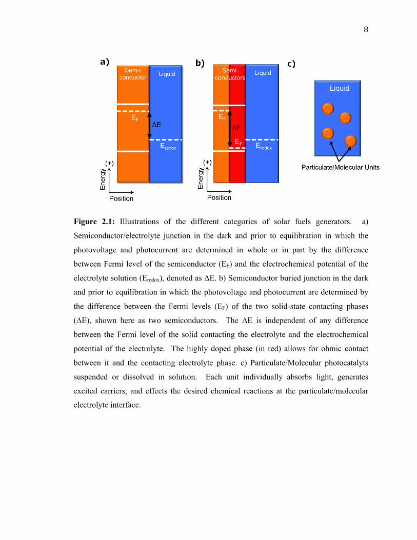
Figure 2.1: Illustrations of the different categories of solar fuels generators. a)
Semiconductor/electrolyte junction in the dark and prior to equilibration in which the
photovoltage and photocurrent are determined in whole or in part by the difference
between Fermi level of the semiconductor (EF) and the electrochemical potential of the
electrolyte solution (Eredox), denoted as ΔE. b) Semiconductor buried junction in the dark
and prior to equilibration in which the photovoltage and photocurrent are determined by
the difference between the Fermi levels (EF) of the two solid-state contacting phases
(ΔE), shown here as two semiconductors. The ΔE is independent of any difference
between the Fermi level of the solid contacting the electrolyte and the electrochemical
potential of the electrolyte. The highly doped phase (in red) allows for ohmic contact
between it and the contacting electrolyte phase. c) Particulate/Molecular photocatalyts
suspended or dissolved in solution. Each unit individually absorbs light, generates
excited carriers, and effects the desired chemical reactions at the particulate/molecular
electrolyte interface.
9
The development of an artificial photosynthetic process, whereby the energy from
sunlight is captured and stored in the chemical bonds of a fuel, has been an active area of
research for decades. This field of research, however, has recently undergone rapid
expansion due to the promise of a scalable solar fuels generator that would provide a
carbon-neutral source of energy capable of addressing concerns about the impact of
carbon emissions on the climate while providing a measure of environmental and energy
security. Researchers have developed a diverse set of designs for solar fuels generators
(Figure 2.1), each of which presents unique challenges associated with the research and
development required to obtain a fully operational system. Furthermore, the maturity of
the technologies being implemented in the various designs varies widely. Despite these
differences, a variety of solar fuels generators are often grouped together and denoted as
“photoelectrochemical cells”. The focus of this chapter is to establish a differentiating
nomenclature and taxonomy for solar fuels generators that clearly identify the principles
underlying the designs. We hope that adoption of this taxonomy (Scheme 2.I) will bring
clarity and precision to discussions and comparisons of solar fuels devices while
facilitating concise and consistent identification of the research challenges and state-of-
the-art for each type of system.
10
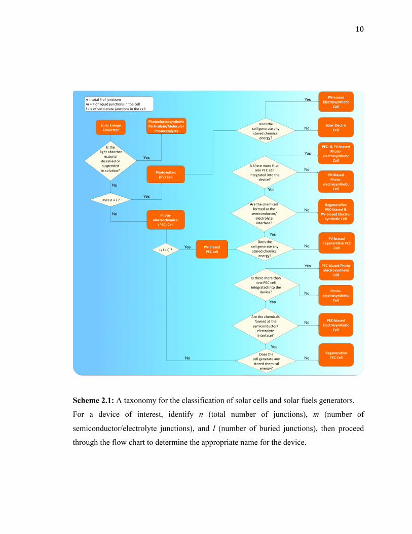
Scheme 2.1: A taxonomy for the classification of solar cells and solar fuels generators.
For a device of interest, identify n (total number of junctions), m (number of
semiconductor/electrolyte junctions), and l (number of buried junctions), then proceed
through the flow chart to determine the appropriate name for the device.
PV#biased**PEC*cell*
Is#the##light#absorber#
material#dissolved#or#suspended##in#solu4on?#
#
Solar*Energy*Converter*
Photo#electrochemical**
(PEC)*Cell*
n#=#total###of#junc4ons#m#=###of#liquid#junc4ons#in#the#cell#l$=###of#solid<state#junc4ons#in#the#cell#
Does#n#=#l$?#
Photovoltaic**(PV)*Cell*
Yes
No
Regenera<ve**PEC#biased*&**
PV#biased*Electro#synthe<c*Cell*
PV#biased**Photo#
electrosynthe<c*Cell*
PV#biased**Regenera<ve*PEC*
Cell*
PV#biased*Electrosynthe<c**
Cell*
Solar*Electric**Cell*
Photoelectrosynthe<c*Par<culate/Molecular*
Photocatalysts*
Does#the##cell#generate#any#stored#chemical#
energy?#
Yes
Yes
Yes
Yes
Yes
No
No
No
No
Is#l#>#0#?#
Does#the##cell#generate#any#stored#chemical#
energy?#
No
Are#the#chemicals#formed#at#the#semiconductor/
electrolyte#interface?#
PEC#biased*Electrosynthe<c*
Cell*
Photo#electrosynthe<c*
Cell*
Regenera<ve**PEC*Cell*
Yes
No
PEC#*&*PV#biased**Photo#
electrosynthe<c*Cell*
Is#there#more#than#one#PEC#cell#
integrated#into#the#device?#
Yes
Does#the##cell#generate#any#stored#chemical#
energy?#
Yes
Is#there#more#than#one#PEC#cell#
integrated#into#the#device?#
No
No Are#the#chemicals#formed#at#the#semiconductor/
electrolyte#interface?#
PEC#biased*Photo#electrosynthe<c*
Cell*
No
Yes
11
All solar fuels generators require an electrical asymmetry to separate and
transport photogenerated charge carriers vectorially.1-4 Without vectorial separation and
transport, the charge carriers, and thus the chemical products, would have no net
directionality and thus would undergo no net separation. Therefore, deleterious
recombination of charge carriers and/or a loss of chemical potential in the resulting
fuel/oxidant mixture would result. The required vectorial separation can be effected by
chemical and/or electrical potential gradients as well as by kinetic asymmetries at the
interface between two unlike materials.1-4 We refer to this interface as a ‘junction’. We
note that our usage of the term “junction” differentiates such an interface from an
interface between two unlike materials that does not result in an asymmetry which
produces a vectorial charge separation.5 We propose that the various solar-fuels
generators can be differentiated at a fundamental level based on the underlying principles
used to accomplish vectorial charge separation and by the method in which the separated
charge is used to effect the synthesis of chemical fuels.
2.2 Photovoltaic Cells
One fundamentally identifiable approach to charge separation in solar fuels
devices is through the use of solid-state, or buried, junctions. Buried junctions are
exclusively formed at the interface between two electronic conductors (as opposed to
ionic conductors, vide infra) and are the basis for the operation of photovoltaic (PV) cells
(Figure 2.2a).6-8 In a device utilizing a buried junction, the photovoltage and photocurrent
produced in the presence of illumination arise from charge separation mediated by a
difference in electrochemical potential (Figure 2.1b) and/or by a difference in charge-
transfer kinetics between two unlike solids that are in mutual electrical contact.
12
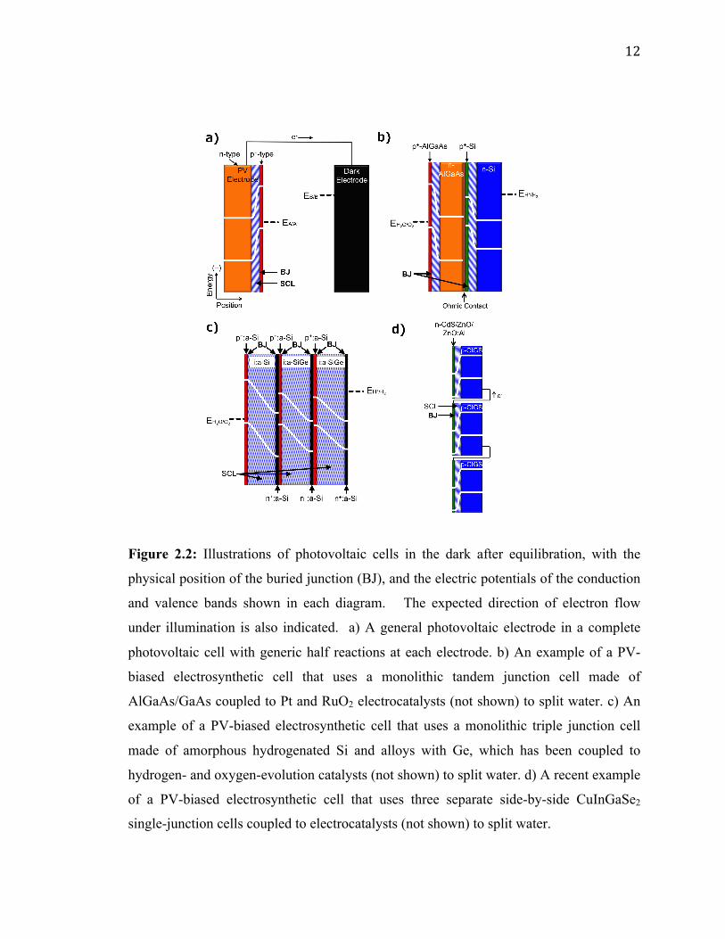
Figure 2.2: Illustrations of photovoltaic cells in the dark after equilibration, with the
physical position of the buried junction (BJ), and the electric potentials of the conduction
and valence bands shown in each diagram. The expected direction of electron flow
under illumination is also indicated. a) A general photovoltaic electrode in a complete
photovoltaic cell with generic half reactions at each electrode. b) An example of a PV-
biased electrosynthetic cell that uses a monolithic tandem junction cell made of
AlGaAs/GaAs coupled to Pt and RuO2 electrocatalysts (not shown) to split water. c) An
example of a PV-biased electrosynthetic cell that uses a monolithic triple junction cell
made of amorphous hydrogenated Si and alloys with Ge, which has been coupled to
hydrogen- and oxygen-evolution catalysts (not shown) to split water. d) A recent example
of a PV-biased electrosynthetic cell that uses three separate side-by-side CuInGaSe2
single-junction cells coupled to electrocatalysts (not shown) to split water.
13
The photocurrent vs. voltage behavior of a PV cell is independent of the character
of any solid/electrolyte interfaces in the system. Therefore, measurements of the
photocurrent-voltage characteristics of the PV cell can be performed independently of
any electrochemical reaction, and can be used in concert with the current-voltage
characteristics of various electrocatalysts to accurately predict the performance of a
complete solar fuels generator that is based on a PV cell. PV cells will also produce the
identical photocurrent-voltage behavior when both terminals of the device are contacted
with wires connected to electrocatalysts vs. when all of the components of the structure
(light absorbers and electrocatalysts) are integrated, contacted intimately, and immersed
in an electrolyte solution. The operating principles of photovoltaic electrodes have been
well documented for incorporation into full PV cells that either produce electricity or
fuels.3
PV cells that produce electricity are referred to as solar electric cells and are
widely available commercially. PV cells that produce fuels are referred to as PV-biased
electrosynthetic cells and can consist of any number of buried junctions arranged
electrically in series with electrocatalysts submerged in an electrolyte. The
electrocatalysts may or may not be in physical contact with the PV electrodes, but in all
such systems the photovoltage generated by the structure is independent of the nature of
the electrocatalyst/electrolyte interface. Examples of PV-biased electrosynthetic cells
include AlGaAs/GaAs tandem structures,9 amorphous hydrogenated Si (a-Si:H) triple-
junction structures,10-12 triple-junction structures based on CuInGaSe2 (Figure 2.2b-d),13
and n-Si/SiOx/In-doped Tin Oxide (ITO) structures.14
14
The advantages of PV-based solar fuels generators are the high reported solar-to-
fuels efficiencies and the independence of the power-producing junction with respect to
the formal potential for the reactions of interest.15 The challenges associated with PV-
based cells include achieving a cost advantage for a system with the functioning
photovoltaic cell immersed in the electrolyte, relative to a system that utilizes a discrete
photovoltaic cell in dry conditions wired to a discrete fuel-forming device, as well as
finding catalyst/ electrolyte interfaces that are transparent, conductive, and stable under
operational, fuel-forming conditions. 11, 12, 15-18 Thus, the key research needs involve the
development of cost-competitive photovoltaic cells, the integration of components,
discovery of materials, development of low-cost fabrication methods, and the
stabilization of electrodes through the use of materials that act as transparent and
conductive protecting layers.
2.3 Photoelectrochemical Cells
Another fundamentally identifiable approach to effect the separation of charge
carriers is through the use of a solid/ionic-conductor junction. Devices utilizing
solid/ionic-conductor junctions, also referred to as solid/electrolyte junctions, are called
photoelectrochemical (PEC) cells (Figure 2.3a). The solid in a PEC cell is commonly a
semiconductor and may or may not have an attached photosensitizer. Other solids,
including metals such as platinum and mercury, have also been observed to produce a
photovoltage at a solid/ electrolyte interface when the appropriate electrolyte is
present.19,2019, 20
15
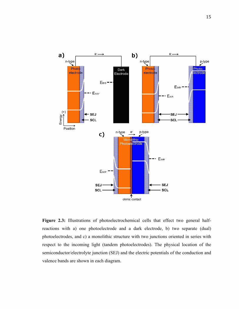
Figure 2.3: Illustrations of photoelectrochemical cells that effect two general half-
reactions with a) one photoelectrode and a dark electrode, b) two separate (dual)
photoelectrodes, and c) a monolithic structure with two junctions oriented in series with
respect to the incoming light (tandem photoelectrodes). The physical location of the
semiconductor/electrolyte junction (SEJ) and the electric potentials of the conduction and
valence bands are shown in each diagram.
16
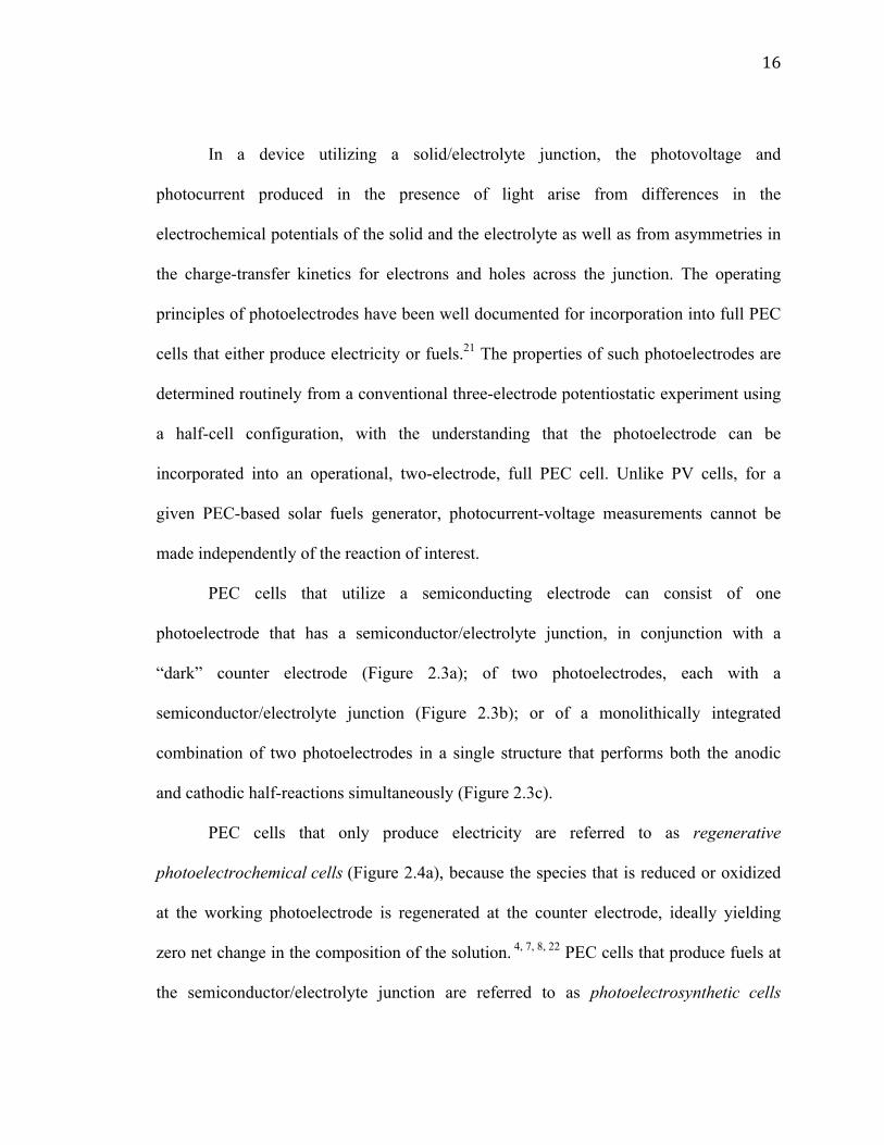
In a device utilizing a solid/electrolyte junction, the photovoltage and
photocurrent produced in the presence of light arise from differences in the
electrochemical potentials of the solid and the electrolyte as well as from asymmetries in
the charge-transfer kinetics for electrons and holes across the junction. The operating
principles of photoelectrodes have been well documented for incorporation into full PEC
cells that either produce electricity or fuels.21 The properties of such photoelectrodes are
determined routinely from a conventional three-electrode potentiostatic experiment using
a half-cell configuration, with the understanding that the photoelectrode can be
incorporated into an operational, two-electrode, full PEC cell. Unlike PV cells, for a
given PEC-based solar fuels generator, photocurrent-voltage measurements cannot be
made independently of the reaction of interest.
PEC cells that utilize a semiconducting electrode can consist of one
photoelectrode that has a semiconductor/electrolyte junction, in conjunction with a
“dark” counter electrode (Figure 2.3a); of two photoelectrodes, each with a
semiconductor/electrolyte junction (Figure 2.3b); or of a monolithically integrated
combination of two photoelectrodes in a single structure that performs both the anodic
and cathodic half-reactions simultaneously (Figure 2.3c).
PEC cells that only produce electricity are referred to as regenerative
photoelectrochemical cells (Figure 2.4a), because the species that is reduced or oxidized
at the working photoelectrode is regenerated at the counter electrode, ideally yielding
zero net change in the composition of the solution. 4, 7, 8, 22 PEC cells that produce fuels at
the semiconductor/electrolyte junction are referred to as photoelectrosynthetic cells

17
(Figure 2.4b).7, 23, 24 An example of a regenerative PEC cell is the n-Si/CH3OH-
1,1’dimethylferrocene/ITO cell (Figure 2.4c, n-Si is the photoelectrode).25 Dye-sensitized
solar cells (DSSCs) are also commonly operated as regenerative PEC cells.26 Examples
of photoelectrosynthetic PEC cells include n-SrTiO3/NaOH(aq)/Pt cells for water
splitting (Figure 2.4d, SrTiO3 is the photoelectrode) 27, n-MoS2/Pt cells for the production
of H2 and I2 from HI(aq) (Figure 2.4e, n-MoS2 is the photoelectrode) 28, and DSSC’s
including TiO2 photosensitized with a catalytic molecular [(PO3H2)2bpy)2Ru(4-Mebpy-4-
bimpy)Ru(tpy)(OH2)]4+ unit for water splitting, as well as others. 29-31
18
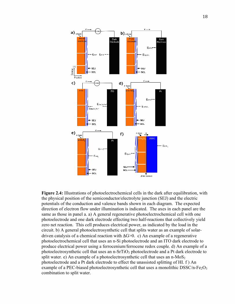
Figure 2.4: Illustrations of photoelectrochemical cells in the dark after equilibration, with the physical position of the semiconductor/electrolyte junction (SEJ) and the electric potentials of the conduction and valence bands shown in each diagram. The expected direction of electron flow under illumination is indicated. The axes in each panel are the same as those in panel a. a) A general regenerative photoelectrochemical cell with one photoelectrode and one dark electrode effecting two half-reactions that collectively yield zero net reaction. This cell produces electrical power, as indicated by the load in the circuit. b) A general photoelectrosynthetic cell that splits water as an example of solar-driven catalysis of a chemical reaction with ΔG>0. c) An example of a regenerative photoelectrochemical cell that uses an n-Si photoelectrode and an ITO dark electrode to produce electrical power using a ferrocenium/ferrocene redox couple. d) An example of a photoelectrosynthetic cell that uses an n-SrTiO3 photoelectrode and a Pt dark electrode to split water. e) An example of a photoelectrosynthetic cell that uses an n-MoS2 photoelectrode and a Pt dark electrode to effect the unassisted splitting of HI. f ) An example of a PEC-biased photoelectrosynthetic cell that uses a monolithic DSSC/n-Fe2O3 combination to split water.
19
The product of coupling a regenerative PEC cell to metallic electrodes produces a
PEC-biased electrosynthetic cell, whereas the product of coupling a regenerative PEC
cell to a photoelectrosynthetic PEC cell is referred to as a PEC-biased
photoelectrosynthetic cell. Photoelectrochemical cells, like photovoltaic cells, can be
used to bias both PEC and PV cells to assist in fuel formation. An example of a PEC-
biased photoelectrosynthetic cell is a DSSC placed electrically in series with an
Fe2O3/electrolyte junction cell for water splitting (Figure 4f). 32 Here, the DSSC is a free-
standing, two-terminal device whose photocurrent and photovoltage are independent of
the fuel-forming reactions of interest, but which operates as a PEC nonetheless because
the photocurrent and photovoltage are not independent of the solution at the interface of
the two terminals of the DSSC itself.
The performance of photoelectrodes consisting of semiconductor/electrolyte
junctions, in the absence of bulk semiconductor limitations, is determined by the
energetics and kinetics of the semiconductor/electrolyte interface. The interfacial
energetics determine the photovoltage through the difference between the formal
potential of the fuel-forming reaction of interest and the electrochemical potential of the
semiconductor, 18, 33, 34 and also determine the driving force needed to produce a given
current density. Commonly, an electrocatalyst is incorporated at the
semiconductor/electrolyte interface to improve the interfacial charge-transfer kinetics;
however, for the device to remain categorized as a PEC cell, the nature of the electrolyte
must affect the performance of the cell.35 Examples of PEC cells with electrocatalysts
incorporated at the semiconductor/electrolyte interface include H2-evolving
photocathodes made from metal islands or thin metallic films on p-Si or p-InP
20
photoelectrodes, because the work function of the metal, and thus the barrier height at the
semiconductor surface, depends on the concentration of H2 in the electrolyte.36, 37
Semiconductor/electrolyte junctions with ion-permeable, redox-active electrocatalysts
would also be considered PEC cells because of the electrolyte-dependent behavior of the
device. 35 In addition, recent progress on stabilization schemes based on thin coatings on
the surface of the semiconductor has produced examples of photoelectrodes in which the
solution potential affects the photovoltage even though the photoelectrode is not in direct
physical contact with the solution.38, 39 Conversely, electrocatalysts deposited on
semiconductors, such as CoPi on Fe2O3, are reported to convert what would otherwise be
photoelectrosynthetic cells into photovoltaic electrosynthetic cells, by formation of a
Schottky junction at the semiconductor/catalyst junction.40-42 Careful evaluation is often
necessary to determine whether a device is a PV or PEC cell when electrocatalysts are
present on the surface. Data, including the current-voltage characteristics of the catalyst
alone, the photocurrent-voltage characteristics of the semiconductor with and without the
presence of the electrocatalyst, the photocurrent-voltage behavior of the semiconductor
with and without electrocatalyst in contact with electrolytes of varying composition and
electrochemical potential, and laser spectroscopic data on the electron-hole
recombination mechanism in the presence or absence of electrocatalyst, may be necessary
to ascertain whether such a system is properly classified as a PV or PEC cell.
The principal advantages of PEC cells are their simplicity of fabrication and the
finding that inexpensive polycrystalline semiconductor/electrolyte junctions can often
perform nearly as well as their single crystalline counterparts. 43-45 The challenges
associated with PEC cells include obtaining a combination of materials that are
21
operationally stable and also possess appropriate interfacial energetics and band gaps, as
well as the development and integration of electrocatalysts into the
semiconductor/electrolyte junction. Thus, the key research needs for solar fuels
generators based on PEC cells involve the discovery and development of semiconducting
materials that possess both the proper band gaps for effective sunlight absorption and
well-positioned band energetics, and the development of methods for incorporating
efficient electrocatalysts into semiconductor/electrolyte interfaces that are stable under
operational, fuel-forming conditions.18, 46-49
2.3.1 Photovoltaic-‐Biased Photoelectrochemical Cells
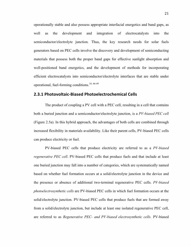
The product of coupling a PV cell with a PEC cell, resulting in a cell that contains
both a buried junction and a semiconductor/electrolyte junction, is a PV-biased PEC cell
(Figure 2.5a). In this hybrid approach, the advantages of both cells are combined through
increased flexibility in materials availability. Like their parent cells, PV-biased PEC cells
can produce electricity or fuel.
PV-biased PEC cells that produce electricity are referred to as a PV-biased
regenerative PEC cell. PV-biased PEC cells that produce fuels and that include at least
one buried junction may fall into a number of categories, which are systematically named
based on whether fuel formation occurs at a solid/electrolyte junction in the device and
the presence or absence of additional two-terminal regenerative PEC cells. PV-biased
photoelectrosynthetic cells are PV-biased PEC cells in which fuel formation occurs at the
solid/electrolyte junction. PV-biased PEC cells that produce fuels that are formed away
from a solid/electrolyte junction, but include at least one isolated regenerative PEC cell,
are referred to as Regenerative PEC- and PV-biased electrosynthetic cells. PV-biased

22
PEC cells that include at least one isolated regenerative PEC cell, but that produce fuels
that are formed at a solid/electrolyte junction, are referred to as Regenerative PEC- and
PV-biased photoelectrosynthetic cells. Examples of PV-biased PEC cells include the
“Turner Cell”, a GaAs buried junction electrically in series and monolithically integrated
with a p-GaInP2/electrolyte junction (Figure 2.5b), as well as an a-Si:H PV cell
electrically in series with a BiVO4/electrolyte junction (Figure 2.5c) and the PEC cells
often referred to as ‘septum-based PEC cells’. 50-54
23
Figure 2.5: Illustrations of photovoltaic-biased photoelectrochemical cells in the dark after equilibration, with the physical position of the semiconductor/electrolyte junction (SEJ), the buried junction (BJ), and the electric potentials of the conduction and valence bands shown in each diagram. The expected direction of electron flow under illumination is indicated. The axes in each panel are the same as those in panel a. a) A general photovoltaic-biased photoelectrochemical cell comprising one photovoltaic electrode and one photoelectrochemical electrode that effects two general half-reactions. b) An example of a photovoltaic-biased photoelectrochemical cell that uses tandem photoelectrodes, one utilizing a GaInP/electrolyte junction and the other utilizing a GaAs buried junction, to drive water splitting. c) A recent example of a photovoltaic-biased photoelectrochemical cell that uses tandem photoelectrodes, one utilizing a BiVO4/electrolyte junction and the other utilizing an amorphous hydrogenated Si buried junction, to drive water splitting.
24
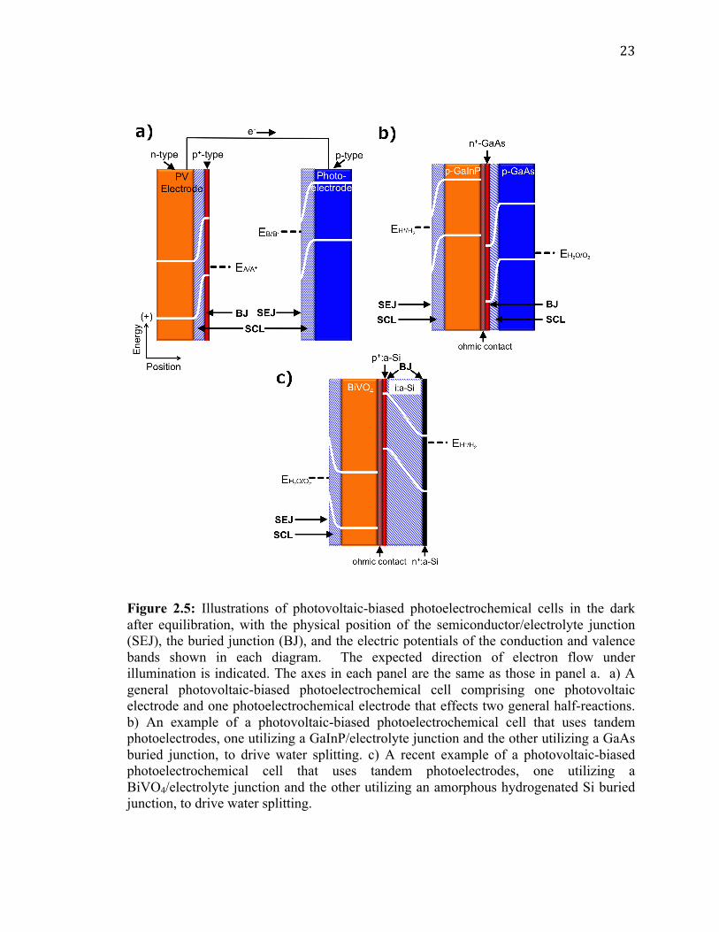
2.4 Photoelectrosynthetic Particulate/Molecular Photocatalysts
Both the buried junction and the semiconductor/electrolyte junction motifs can be
employed when the semiconducting material is employed in a dispersed particulate form
as opposed to a solid electrode (Figure 2.6). In these particulate systems, the photovoltage
and photocurrent that drive the interfacial electrochemical reactions in the presence of
illumination are developed as a result of semiconductor/electrolyte and/or buried
junctions in a single discrete particle unit that generally contains separate co-catalysts for
each half-reaction. 55
Figure 2.6: Illustration of a photocatalytic particle in the dark after equilibration, with the
physical position of the semiconductor/electrolyte junction (SEJ) and the electric
potentials of the conduction and valence bands shown in the diagram. This photocatalytic
particle is shown performing water splitting with two separate co-catalysts attached to its
surface. Instead of a semiconductor/electrolyte junction the particle could utilize a buried
junction. In practice, multiple particles are suspended in an electrolyte.
25
Although in theory one could distinguish between particles utilizing buried and
semiconductor/electrolyte junctions in the same way as for the PEC and PV cells, in
practice, these two types of systems are difficult to distinguish experimentally. A
comparison of the photovoltage produced by a particle in solution with that measured
across a particle removed from solution may be difficult or impossible to perform, due to
the small size of the particles and the resulting effective absence of addressable
electrodes. Indirect measurements of the photocurrent and/or photovoltage under varying
conditions may be obtained by correlating changes in the amount of products formed by
the light-driven reaction with various solution compositions, but accurate measurements
of the products will be hindered by product crossover and incompatible catalysts. The
particulate versions of PV and PEC cells, as well as the related photo-driven molecular
photocatalysts wherein inorganic molecular compounds are dispersed in solution, share
many of the same research challenges as their parent categories, with the added challenge
of developing methods to physically separate the products of the fuel-forming reactions.
The term cell does not apply to particulate schemes that employ neither addressable
electrodes nor a built-in means to enforce the separation of products. For these reasons,
we consider all three of these strategies to comprise members of the general category of
photoelectrosynthetic particulate/molecular photocatalysts.7, 56, 57
An example of photoelectrosynthetic particulate photocatalysts are CdS particles
in contact with TiO2 particles, with an electrical asymmetry at the CdS/TiO2 interface. 57-
59 Other examples include a NiO-SrTiO3 photocatalyst capable of concomitantly evolving
H2 and O2, as well as a number of metal nitrides, oxides, and oxynitrides (e.g. ZrO2,
TaON, Ta3N5, WO3).57 Similarly, the performance of a photoelectrosynthetic molecular
26
photocatalyst is based either on monomolecular photochemical processes or on coupled
photoelectrochemical-photochemical or photochemical-dark reactions in an individual
molecular unit. Examples of photoelectrosynthetic molecular cells include light-driven
water splitting by UV irradiation of aqueous Ce(III)/Ce(IV) solutions; 60 the use of
molecular triads or tetrads coupled to nanoparticulate or molecular electrocatalysts for
fuel production;61 the coupling of molecular catalysts to photoactive proteins;62, 63 and
related systems.64, 65
The principal advantages of particulate/molecular photocatalysts are the
simplicity of the photocatalysts relative to other approaches and the associated low
predicted system cost, with a recent technoeconomic analysis suggesting that systems
based on particulate/molecular photocatalysts could be significantly less expensive than
electrode-based systems when deployed at scale.15 The challenges facing development of
systems from photoelectrosynthetic particulate/molecular photocatalysts involve
stabilizing all of the components, addressing safety concerns arising from the production
of explosive mixtures of stoichiometric fuel products, and controlling undesired
recombination processes to realize high steady-state quantum yields for net fuel
production. Specific undesired processes include photogenerated electrons reducing key
surface-bound intermediates, intermediates in solution, or products of the oxidation of
water to O2, as well as photogenerated holes participating in analogous oxidation
reactions, and the spontaneous recombination of the fuels facilitated by contact with the
co-catalysts at any location in the system.
27
2.5 Discussion
Both PV and PEC cells can be structured with multiple junctions to optimize the
theoretical maximum efficiency for a given fuel-forming reaction.66 Single-junction cells
are best suited for fuel-forming reactions that require operating voltages near or below
the ~1 V maximum power point of the single-junction devices that have the highest
reported energy-conversion efficiency.67 Fuel-forming reactions that require larger
voltages also require more junctions to better utilize the solar spectrum, with the optimal
number of junctions being dependent on the voltage required for the operating current
density. Therefore, the maximum realizable efficiencies for water splitting are generally
obtained with a tandem-absorber cell, where two light absorbers with appropriately tuned
band gaps are arranged in series with respect to the incident light.9, 53 Additional junctions
can increase the efficiency of solar devices when the semiconductors have carefully
selected band gaps. 68 Triple-junction cells utilizing a single semiconductor or two
semiconductors have also been used to effect solar-driven water splitting when related
double junction devices were unable to generate sufficient voltage.11, 12, 51 When the same
semiconductor is used to form multiple junctions, the cells suffer from a loss of current to
achieve the necessary voltage for water splitting.
Advanced structuring of PV- and PEC-based solar fuels generators can offer
additional efficiency gains for systems, including those for which all of the components
are in contact with the electrolyte. One example of advanced structuring is an array of p-
Si microwires that have radial n+-doped emitter regions, with an electrocatalyst placed in
specific physical locations between or along the surfaces of the microwires (Figure 2.7).69
Some ambiguity exists regarding the classification of such a system. The mechanism of
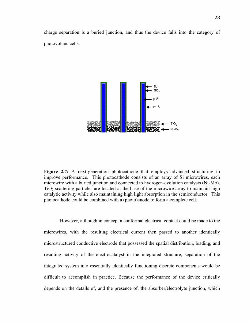
28
charge separation is a buried junction, and thus the device falls into the category of
photovoltaic cells.
Figure 2.7: A next-generation photocathode that employs advanced structuring to improve performance. This photocathode consists of an array of Si microwires, each microwire with a buried junction and connected to hydrogen-evolution catalysts (Ni-Mo). TiO2 scattering particles are located at the base of the microwire array to maintain high catalytic activity while also maintaining high light absorption in the semiconductor. This photocathode could be combined with a (photo)anode to form a complete cell.
However, although in concept a conformal electrical contact could be made to the
microwires, with the resulting electrical current then passed to another identically
microstructured conductive electrode that possessed the spatial distribution, loading, and
resulting activity of the electrocatalyst in the integrated structure, separation of the
integrated system into essentially identically functioning discrete components would be
difficult to accomplish in practice. Because the performance of the device critically
depends on the details of, and the presence of, the absorber/electrolyte junction, which
29
acts in this case in a synergetic fashion with respect to one or more other components of
the integrated system, designation of the device as a photoelectrochemical cell might
seem reasonable. Furthermore, if the microwires are removed from the substrate and
embedded in an immobilizing membrane, they may be deemed similar to a
photoelectrosynthetic particulate photocatalyst. In this case, however, the uniform
particle orientation and built-in barrier for product separation would produce a
photoelectrosynthetic particulate cell rather than a photoelectrosynthetic particulate
photocatalyst. This discussion serves to emphasize that while some devices easily fall
into a single taxonomic classification and therefore are subject to the research challenges
associated with that classification, other devices may have characteristics of multiple
classifications with some or all of the related challenges, advantages, or disadvantages.
2.6 Conclusion
Although researchers have developed diverse designs for solar fuels generators
based on a diverse set of underlying principles, solar fuels generators are often grouped
together and denoted as “photoelectrochemical cells”. The purpose of this chapter is not
to favor, or establish a bias or preference towards, any specific design or approach. The
different performance/cost/function trade-offs associated with each approach ultimately
will determine which of these distinct technological approaches to the development of
solar fuels generators will prove viable in the marketplace. Instead, we have described a
taxonomy for solar fuels generators that is based on the operating principles underlying
the designs, to bring clarity and precision to discussions of research in the field of
artificial photosynthesis while facilitating concise and consistent identification of the
research challenges and state-of-the-art for each type of system.

30
2.7 Acknowledgements
The bulk of the above work appeared in Energy and Environmental Science in
2015 (DOI: 10.1039/c4ee02251c). Matthew R. Shaner, Kimberly M. Papadantonakis, and
Sonja A. Francis are thanked for their extensive and invaluable contributions.
31
2.8 References
1. A. J. Bard and M. A. Fox, Acc. Chem. Res., 1995, 28, 141-145.
2. S. J. Fonash, Solar Cell Device Physics, Elsevier Inc., Amsterdam, 2nd edn.,
2010.
3. N. Serpone and E. Pelizzetti, Photocatalysis: Fundamentals and Applications,
John Wiley & Sons, Inc., Hoboken, NJ, 1989.
4. M. X. Tan, P. E. Laibinis, S. T. Nguyen, J. M. Kesselman, C. E. Stanton and N. S.
Lewis, in Prog. Inorg. Chem., ed. K. D. Karlin, John Wiley & Sons, Inc., 1994.
5. Within this Opinion, we specifically denote as ‘junctions’ those interfaces whose
electrical asymmetry leads to the development of a photovoltage or photocurrent
upon illumination. In other contexts, the interface between two materials that do
not generate a photocurrent or photovoltage under illumination, such as ohmic
contacts, may also be referred to as a ‘junction’.
6. The term ‘photovoltaic’ has been used in a number of contexts, including to
denote any device that generates a measurable photocurrent or photovoltage upon
illumination, including specifically photoelectrochemical cells (references 7,8).
This usage is defendable because both PV and PEC cells exhibit a photovolatic
effect as understood by the strict definition of the term ‘photovoltaic’. However,
as alluded to in reference 8, photoelectrochemical cells are commonly
differentiated from cells that utilize a junction between two electronic conductors,
to emphasis the different underlying princples in the two different types of
systems. The term ‘photovoltaic’ is therefore used herein to refer to only those
devices that include a junction between electronic conductors.
32
7. A. J. Bard, R. Memming and B. Miller, Pure Appl. Chem., 1991, 63, 569-596.
8. S. Licht, ed., Semiconductor Electrochemistry and Photoelectrochemistry, Wiley-
VCH, Weinheim, Germany, 2002.
9. S. Licht, B. Wang, S. Mukerji, T. Soga, M. Umeno and H. Tributsch, J. Phys.
Chem. B, 2000, 104, 8920-8924.
10. USA Pat., 4,466,869, 1984.
11. S. Y. Reece, J. A. Hamel, K. Sung, T. D. Jarvi, A. J. Esswein, J. J. H. Pijpers and
D. G. Nocera, Science, 2011, 334, 645-648.
12. R. E. Rocheleau, E. L. Miller and A. Misra, Energy Fuels, 1998, 12, 3-10.
13. T. J. Jacobsson, V. Fjallstrom, M. Sahlberg, M. Edoff and T. Edvinsson, Energy
& Environmental Science, 2013, 6, 3676-3683.
14. G. Hodes, L. Thompson, J. DuBow and K. Rajeshwar, J. Am. Chem. Soc., 1983,
105, 324-330.
15. B. D. James, G. N. Baum, J. Perez and K. N. Baum, Technoeconomic Analysis of
Photoelectrochemical (PEC) Hydrogen Production, 2009.
16. A. J. Bard and M. S. Wrighton, Journal of The Electrochemical Society, 1977,
124, 1706-1710.
17. R. Noufi, A. J. Frank and A. J. Nozik, J. Am. Chem. Soc., 1981, 103, 1849-1850.
18. M. G. Walter, E. L. Warren, J. R. McKone, S. W. Boettcher, Q. Mi, E. A. Santori
and N. S. Lewis, Chem. Rev., 2010, 110, 6446-6473.
19. M. Heyrovsky and R. G. W. Norrish, Nature, 1963, 200, 880-881.
20. W. J. Albery, Acc. Chem. Res., 1982, 15, 142-148.
21. B. Parkinson, Acc. Chem. Res., 1984, 17, 431-437.
33
22. In accordance with references 4 and 8, we have chosen to use the term
‘regenerative photoelectrochemical cell’ to denote a cell that utilizes a
solid/electrolyte junction to generate electricity, with no net chemical conversion,
under illumination. This usage in contrast to that of reference 7, which refers to
these systems as ‘photovoltaic’ devices. As described above, we have reserved the
term ‘photovoltaic’ to denote a system that utilizes a junction between two
electronic conductors, in accord with broad usage and with the definition in many
dictionaries of the term “photovoltaic”.
23. In accordance with reference 24, we have used the term ‘photoelectrosynthetic’ to
encompass all devices in which a net chemical conversion takes place. We
recognize that the term ‘photoelectrolytic’ has been used (e.g., ref 7) in this
context to refer to devices in which a net chemical conversion occurs with ΔG>0,
and the term ‘photocatalytic’ has been used to refer to devices with ΔG<0. We
chose our nomenclature to avoid confusion with the common usage of the term
‘photocatalyst’.
24. J. Connolly, ed., Photochemical conversion and storage of solar energy,
Academic Press, New York, 1981.
25. C. M. Gronet, N. S. Lewis, G. Cogan and J. Gibbons, Proc. Nat. Acad. Sci. USA,
1983, 80, 1152-1156.
26. M. Grätzel, J. Photochem. Photobiol. C, 2003, 4, 145-153.
27. M. S. Wrighton, A. B. Ellis, P. T. Wolczanski, D. L. Morse, H. B. Abrahamson
and D. S. Ginley, J. Am. Chem. Soc., 1976, 98, 2774-2779.
34
28. C. Levy‐Clement, A. Heller, W. A. Bonner and B. A. Parkinson, Journal of The
Electrochemical Society, 1982, 129, 1701-1705.
29. L. Alibabaei, M. K. Brennaman, M. R. Norris, B. Kalanyan, W. Song, M. D.
Losego, J. J. Concepcion, R. A. Binstead, G. N. Parsons and T. J. Meyer, Proc.
Nat. Acad. Sci. USA, 2013, DOI: 10.1073/pnas.1319628110.
30. J. R. Swierk and T. E. Mallouk, Chem. Soc. Rev., 2013, 42, 2357-2387.
31. K. J. Young, L. A. Martini, R. L. Milot, R. C. Snoeberger Iii, V. S. Batista, C. A.
Schmuttenmaer, R. H. Crabtree and G. W. Brudvig, Coord. Chem. Rev., 2012,
256, 2503-2520.
32. J. Brillet, J.-H. Yum, M. Cornuz, T. Hisatomi, R. Solarska, J. Augustynski, M.
Graetzel and K. Sivula, Nat. Photonics, 2012, 6, 824-828.
33. R. van de Krol, Y. Liang and J. Schoonman, Journal of Materials Chemistry,
2008, 18, 2311-2320.
34. H.-J. Lewerenz and L. Peter, Photoelectrochemical Water Splitting, The Royal
Society of Chemistry.
35. F. Lin and S. W. Boettcher, Nature Materials, 2014, 13, 81-86.
36. E. Aharon‐Shalom and A. Heller, Journal of The Electrochemical Society, 1982,
129, 2865-2866.
37. R. N. Dominey, N. S. Lewis, J. A. Bruce, D. C. Bookbinder and M. S. Wrighton,
J. Am. Chem. Soc., 1982, 104, 467-482.
38. N. C. Strandwitz, D. J. Comstock, R. L. Grimm, A. C. Nichols-Nielander, J. Elam
and N. S. Lewis, J. Phys. Chem. C, 2013, 117, 4931-4936.

35
39. A. C. Nielander, M. J. Bierman, N. Petrone, N. C. Strandwitz, S. Ardo, F. Yang,
J. Hone and N. S. Lewis, J. Am. Chem. Soc., 2013, 135, 17246-17249.
40. M. Barroso, A. J. Cowan, S. R. Pendlebury, M. Grätzel, D. R. Klug and J. R.
Durrant, J. Am. Chem. Soc., 2011, 133, 14868-14871.
41. M. Barroso, C. A. Mesa, S. R. Pendlebury, A. J. Cowan, T. Hisatomi, K. Sivula,
M. Grätzel, D. R. Klug and J. R. Durrant, Proc. Nat. Acad. Sci. USA, 2012, 109,
15640-15645.
42. M. Barroso, S. R. Pendlebury, A. J. Cowan and J. R. Durrant, Chemical Science,
2013, 4, 2724-2734.
43. A. Heller, in Photoeffects at Semiconductor-Electrolyte Interfaces, American
Chemical Society, 1981, vol. 146, ch. 4, pp. 57-77.
44. A. Heller, Acc. Chem. Res., 1981, 14, 154-162.
45. S. R. Lunt, L. G. Casagrande, B. J. Tufts and N. S. Lewis, J. Phys. Chem. 1988,
92, 5766-5770.
46. N. S. Lewis and G. Crabtree, ed. U. S. D. O. E. Office of Science, Washington,
DC, 2005.
47. M. F. Weber and M. J. Dignam, J. Electrochem. Soc., 1984, 131, 1258-1265.
48. S. Hu, C. Xiang, S. Haussener, A. D. Berger and N. S. Lewis, Energy &
Environmental Science, 2013, 6, 2984-2993.
49. M. F. Weber and M. J. Dignam, Int. J. Hydrogen Energy, 1986, 11, 225-232.
50. Although the Turner Cell (reference 53) is classified as a PV-Biased PEC cell, the
surface of the p-GaInP2 at the p-GaInP2/3M H2SO4(aq) interface is covered in a
thin layer of Pt. This suggests the possibility that the I-V characteristics of this
36
device may be independent of the nature of the electrolyte at the p-GaInP2/3M
H2SO4(aq) interface, which would then result in the appropriate designation of
this cell as a PV-Biased electrosynthetic cell. However, as noted in ref 35, the I-V
behavior of electrodes consisting of thin layers of Pt on semiconductors is often
dependent on the pH of the electrolyte. Thus, based on the available data, is not
clear whether the Turner Cell is more appropriately designated as PV-Biased
photoelectrosynthetic cell or as a PV-Biased electrosynthetic cell. A similar
argument is relavent for the devices discussed in reference 51.
51. F. F. Abdi, L. Han, A. H. M. Smets, M. Zeman, B. Dam and R. van de Krol, Nat.
Commun., 2013, 4.
52. A. J. Bard and T. E. Mallouk, J. Phys. Chem., 1993, 97, 7127-7128.
53. O. Khaselev and J. A. Turner, Science, 1998, 280, 425-427.
54. S. C. Kondapaneni, D. Singh and O. N. Srivastava, J. Phys. Chem, 1992, 96,
8094-8099.
55. K. Domen, S. Naito, M. Soma, T. Onishi and K. Tamaru, J. Chem. Soc., Chem.
Commun. 1980, DOI: 10.1039/C39800000543, 543-544.
56. We have used the term ‘photocatalyst’ to describe these systems, in accordance
with common parlance and in accord with the usage of reference 57. We
recognize that ‘photocatalysis’ is often, however, used to refer specifically to the
light-driven catalysis of a reaction for which ΔG<0 (reference 7).
57. T. Hisatomi, J. Kubota and K. Domen, Chem. Soc. Rev., 2014, DOI:
10.1039/C3CS60378D.
37
58. K. R. Gopidas, M. Bohorquez and P. V. Kamat, J. Phys. Chem, 1990, 94, 6435-
6440.
59. N. Serpone, E. Borgarello and M. Gratzel, J. Chem Soc., Chem. Commun., 1984,
DOI: 10.1039/C39840000342, 342-344.
60. J. Weiss and D. Porret, Nature, 1937, 139, 1019-1020.
61. D. Gust, T. A. Moore and A. L. Moore, Acc. Chem. Res., 2009, 42, 1890-1898.
62. S. C. Silver, J. Niklas, P. Du, O. G. Poluektov, D. M. Tiede and L. M. Utschig, J.
Am. Chem. Soc., 2013, 135, 13246-13249.
63. L. M. Utschig, S. C. Silver, K. L. Mulfort and D. M. Tiede, J. Am. Chem. Soc.,
2011, 133, 16334-16337.
64. P. Du, J. Schneider, G. Luo, W. W. Brennessel and R. Eisenberg, Inorg. Chem.,
2009, 48, 4952-4962.
65. B. D. Yuhas, A. L. Smeigh, A. P. Douvalis, M. R. Wasielewski and M. G.
Kanatzidis, J. Am. Chem. Soc., 2012, 134, 10353-10356.
66. J. R. Bolton, S. J. Strickler and J. S. Connolly, Nature, 1985, 316, 495-500.
67. B. M. Kayes, H. Nie, R. Twist, S. G. Spruytte, F. Reinhardt, I. C. Kizilyalli and
G. S. Higashi, presented in part at the 37th IEEE Photovoltaic Specialists
Conference, Seattle, WA, 2011.
68. C. H. Henry, J. Appl. Phys., 1980, 51, 4494-4500.
69. E. L. Warren, J. R. McKone, H. A. Atwater, H. B. Gray and N. S. Lewis, Energy
& Environmental Science, 2012, 5, 9653-9661.