Embed Size (px)
Citation preview

8/6/2019 PT4600
http://slidepdf.com/reader/full/pt4600 1/5
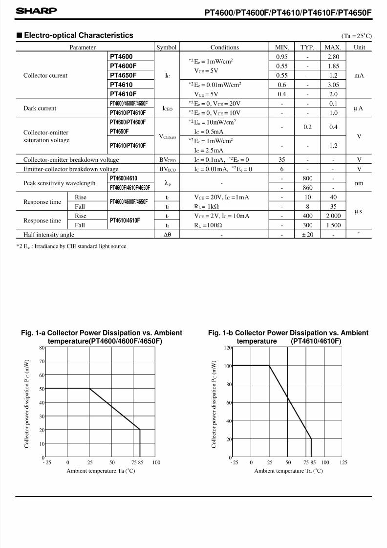
(Ta = 25˚C)
Features
Applications
Outline Dimensions (Unit : mm
Absolute Maximum Ratings
Double Ended Mold TypePhototransistors
1. Compact double ended mold package
PT4600/PT4600F/PT4610/
PF4610F/PF4650F
(Packaging area : 37% smaller than PT480)
Light sensitivity : 3 times as large as PT460 series)
4. Taped model (2,000 pieces/reel) also available
1. Floppy disk drives
2. VCRs
3. Audio equipment
4. Video-movie kits
3. Darlington output type (PT4610), visible light cut-off
type (PT4600F/4610F/4650F), VCR tape end
detection type (PT4650F) available as standard
* Tolerance : ± 0.2 mm
*1 For MAX. 3 seconds at the position of 2.5 mm from the resin edge
Parameter Symbol Rating Unit
Collector-emitter voltage VCEO 35 V
Emitter-collector voltage V 6 V
Collector
currentCI
20mA
50
Collector power
dissipationPC
50mW
100
Operating temperature Topr - 20 to +85 ˚C
Storage temperature Tstg - 40 to +85 ˚C
Soldering temperature Tsol 260 ˚C*1
PT4600/PT4600F/PT4650F
PT4610/PT4610F
PT4610/PT4610F
PT4600/PT4600F/PT4650F
0.7
0.5 0.25
1.8
2.3
3 . 0
3 . 0
4 . 0
0.4
R0.8
0.8
PT4600
PT4600F
PT4650F
PT4610F
PT4610
1
2
2 2
1 1
M I N . 1 4 . 0
M I N . 1 5 . 5
* 2 Mark
2.7MAX.
1 Emitter
2 Collector
* 1 Epoxy resin
PT4600/PT4600F/PT4610/PT4610F/PT4650
2. Narrow beam angle (Half intensity angle : ± 20˚
Model * 1 Resin type * 2
PT4600 Transparent -
PT4600F Black visible light cut-off -
PT4610 Pale blue transparent -
PT4610F Black visible light cut-off Red
PT4650F Black visible light cut-off Yellow
ECO
“ I th b f fi ti b d i ifi ti h t SHARP t k ibilit f d f t th t i i t i f SHARP' d i h i t l
s
s
s
s
8/6/2019 PT4600
http://slidepdf.com/reader/full/pt4600 2/5
(Ta = 25˚C
Parameter Symbol Conditions MIN. TYP. MAX. Unit
Collector current IC
Ee = 1mW/cm2
VCE = 5V
-
mA
-
-
Ee = 0.01mW/cm2
VCE = 5V
-
-
Dark current ICEO
Ee = 0, VCE = 20V - - 0.1µA
Ee = 0, VCE = 10V - - 1.0
VCE(sat)
Ee = 10mW/cm2
IC = 0.5mA- 0.2 0.4
VEe = 1mW/cm2
IC = 2.5mA- - 1.2
Collector-emitter breakdown voltage BVCEO 35 - - V
Emitter-collector breakdown voltage BVECO 6 - - V
Peak sensitivity wavelength λp -- -
nm- -
tr - 40
tf - 35
tr - 2 000
- 1 500tf
Half intensity angle ∆θ - - - ˚
800
860
10
8
400
300
Ambient temperature Ta (˚C) Ambient temperature Ta (˚C)
PT4600
PT4600F
PT4650F
PT4610
PT4610FPT4600/4600F/4650F
PT4600/PT4600F
PT4610/PT4610F
PT4650F
PT4610/PT4610F
PT4600/4610
PT4600F/4610F/4650F
PT4600/4600F/4650F
PT4610/4610F
VCE = 20V, IC =1mA
VCE = 2V, IC = 10mA
*2
*2
IC = 0.1mA, *2Ee = 0
IC = 0.01mA, *2Ee = 0
RL = 1k Ω
RL =100Ω
0.95
0.55
0.55
0.6
0.4
± 20
2.80
1.85
1.2
3.05
2.0
µ s
Fig. 1-a Collector Power Dissipation vs. Ambienttemperature(PT4600/4600F/4650F)
Fig. 1-b Collector Power Dissipation vs. Ambienttemperature (PT4610/4610F)
Electro-optical Characteristics
Rise
Fall
Rise
Fall
Response time
Response time
Collector-emitter
saturation voltage
*2 E e : Irradiance by CIE standard light source
*2
*2
*2
*2
C o l l e c t o r p o w e r d i s s i p a t i o n
P C
( m W )
C o l l e c t o r p o w e r d i s s i p a t i o n
P C
( m W )
- 25 0 25 50 75 1000
10
20
30
40
50
60
70
- 25 0 25 50 75 100 1250
20
40
60
80
100
8585
PT4600/PT4600F/PT4610/PT4610F/PT4650
80 120
s

8/6/2019 PT4600
http://slidepdf.com/reader/full/pt4600 3/5
Ambient temperature Ta (˚C)
Ambient temperature Ta (˚C)
Fig. 3-a Relative Collector Current vs. Ambient
temperature (PT4600/4600F/4650F)
Ambient temperature Ta (˚C)
Ambient temperature Ta (˚C)
D a r k c u r r e n t I C
E O
( A )
D a r k c u r r e n t I C
E O
( A )
Fig. 4-a Collector Current vs. Irradiance(PT4600/4600F/4650F)
Fig. 2-a Dark Current vs. Ambient temperature(PT4600/4600F/4650F)
Fig. 2-b Dark Current vs. Ambient temperature(PT4610/4610F)
Fig. 4-b Collector Current vs. Irradiance(PT4610/4610F)
Fig. 3-b Relative Collector Current vs. Ambient
temperature (PT4610/4610F)
50
75
- 25 500 25 75 100
100
125
150
10 -10
10 -11
10 - 9
5
- 25
5
5
250 50
10 - 6
10
- 7
10 - 8
10 - 4
10 - 5
5
5
5
5
5
100750 25 50 75 100 125
10 - 6
10 - 7
10 - 8
10 - 9
10 - 10
0 25 50 75 100 125 1500
20
40
60
80
100
120
140
160
0 2.5 5.0 7.5 10 12.5 15.0 0.1 1 10
1.0
10
100
0.01 1000.1
VCE = 5V
= 25 C
175
VCE = 20V VCE
= 10V
VCE = 5V2
VCE = 10V
VCE = 5V
= 25˚C
150
EvEe = 1mW/cm
TaTa
PT4610 PT4610F
30
25
20
15
10
5
0
PT4600F/4650F
PT4600
PT4600/PT4600F/PT4610/PT4610F/PT4650
R e l a t i v e c o l l e c t o r c u r r e n t ( % )
R
e l a t i v e c o l l e c t o r c u r r e n t ( % )
C o l l e c t o r c u r r e n t I C
( m A )
C o l l e c t o r c u r r e n t I C
( m A )
= 2 lx
Irradiance Ee (mA/cm2) Irradiance Ee (mW/cm2)

8/6/2019 PT4600
http://slidepdf.com/reader/full/pt4600 4/5
8/6/2019 PT4600
http://slidepdf.com/reader/full/pt4600 5/5
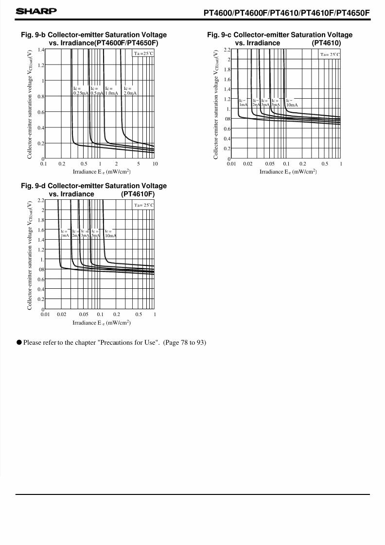
Fig. 9-b Collector-emitter Saturation Voltagevs. Irradiance(PT4600F/PT4650F)
C o l l e c t o r - e m i t t e r s a t u r a t i o n
v o l t a g e V C E ( s a t ) ( V
)
C o l l e c t o r - e m i t t e r s a t u r a t i o n
v o l t a g e V C E ( s a t ) ( V
)
C o l l e c t o r - e m i t t e r s a t u r a t i o n v o l t a g e V C E ( s a t ) ( V
)
Fig. 9-c Collector-emitter Saturation Voltagevs. Irradiance (PT4610)
Fig. 9-d Collector-emitter Saturation Voltagevs. Irradiance (PT4610F)
Please refer to the chapter "Precautions for Use". (Page 78 to 93)
10
0.01 0.1 10
2mA 5mA 10mA
0.4
0.6
0.8
1
1.2
1.4
10.2 20.5 5
Ta =25˚C
Ta= 25˚C2.2
2
1.8
1.6
1.4
1.2
1.
08
0.6
0.4
0.2
Ic =1mA
Ic = Ic = Ic =3mA
Ic =
0.02 0.05 0.2 0.5
0.01 0.1 10
2mA 5mA 10mA
Ta= 25˚C2.2
2
1.8
1.6
1.4
1.2
1.
08
0.6
0.4
0.2
Ic =1mA
Ic= Ic= Ic =3mA
Ic =
0.02 0.05 0.2 0.5
PT4600/PT4600F/PT4610/PT4610F/PT4650
0.1
0.2
0
Ic = Ic = Ic = Ic =
0.25mA 0.5mA 1.0mA 2.0mA
Irradiance E e (mW/cm2)
Irradiance E e (mW/cm2)Irradiance E e (mW/cm2)
q


