Embed Size (px)
Citation preview
1
TO BE REALLYSURE
WWW.VAF.NL
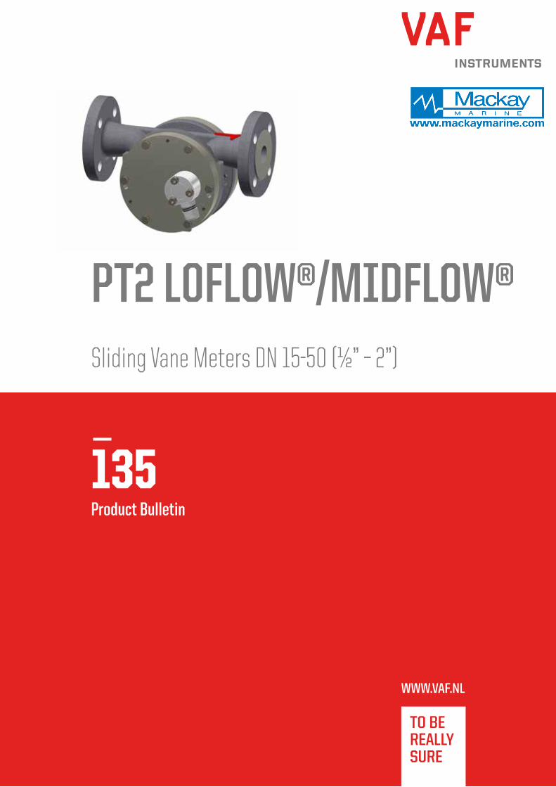
135Product Bulletin
PT2 LOFLOW®/MIDFLOW®Sliding Vane Meters DN 15-50 (½” – 2”)

Introduction VAF Instruments PT2 Flowmeters are used in continuous metering applications. The
positive displacement sliding vane type liquid Flowmeters have a simple, rugged design.
With only few almost frictionless moving internal parts there is hardly any wear in
the Flowmeter which safeguards a typical long lasting lifetime. PT2 meters have no
mechanical seals saving you from regular maintenance and possible leakage of process
liquids into the environment. The Flowmeter is driven by the process liquid which makes it
suitable for distant locations without power supply. The high accuracy of the Flowmeter
(better than 0,2% and repeatability 0,05%) is not influenced by process pressure or
temperature, mechanical pipe strain or liquid turbulence and therefore straight inlet and
outlet pipe pieces are not required.
Experience in flow measurement In 1938 VAF Instruments started as a manufacturer of petrol delivery pumps.
The Flowmeters made by VAF Instruments for this pump already had to have the
highest accuracy and had to meet the demands of the board of weights and measures.
Innovation and research over the past decades helped VAF Instruments to make new
types of Flowmeters bearing in mind customer requirements and the need for accurate
flow measurement. VAF Instruments Flowmeters are available in sizes from 8 mm up to
300 mm (1 l/hr up to 960 m3/hr).
Available PT Flowmeters PT2 Flowmeters are available in connection sizes from 15 mm up to 50 mm representing maximum
flow ranges from 50 l/min up to 500 l/min. The VAF PT2 Flowmeters are designed especially for fuel
consumption measurement under difficult circumstances e.g. on board of ships.
Reversed flow directionFor applications where the flow direction can also be in reverse a special version of
the pulse transmitter has been developed; the PTtwin. To detect the flow direction,
the PTtwin has two Hall switches installed in the cover instead of one. The phase shift
between both signals indicates the flow direction. In case the return flow or backflow is
unwanted a special connection box can be supplied, together with the Flowmeter. The box
has an integrated pulse discriminator, which ensures that the system will only provide
pulse signals when the flow is in the correct direction.
Liquids Other available models of VAF Instruments positive displacement Flowmeters are suitable
for a wide range of liquids. Because liquids with higher viscosities do not degrade the
accuracy of the sliding vane Flowmeter, it is possible to use only one Flowmeter for
various liquids. PT2 Flowmeters are specially developed for measurement of all kinds of
hydrocarbon liquids in particular medium and heavy fuel oils for combustion engines,
lubricating oils and many other oil-like liquids. VAF PT2 Flowmeters can be delivered with
various combinations of counters/flow computers. Refer to Application Bulletin AB-124
for Fuel Consumption Measurement. Consult our factory for the selection of the
suitable model.
.
Principle of operationVAF Instruments positive displacement Flowmeters operate on the sliding vane principle. The meter
consists of a specially shaped housing in which a rotor can rotate freely. Two pairs of vanes are
placed into four slots in the rotor. Each pair is positioned by a rod and can move in and out of the
rotor. The radial movement of the vanes is guided by the special inner shape of the housing.
This patented construction provides a constant seal between the inlet and the outlet of the meter.
The incoming liquid forces the rotor to rotate. For protection of the Flowmeter appropriate liquid
filtering is essential.
The rotation of the rotor is transferred via one or two (PTtwin) Hall switches mounted in the
cover. This switch can be used for remote read out, flow data processing or connection to a
process computer.
RotorVaneVane rod
Section view of a PT2 Flowmeter
PT2 SensorMagnetBearing

Applications of flow measurement
Flow measurement is used for a wide range of applications. Fuel
consumption measurement can be performed in engine-driven
installations in all kinds of power and propulsion plants. Various types
of fuel can be measured, such as heavy fuel oil, diesel oil or bio-oil.
Depending on the type of fuel system it is necessary to have one,
two or three Flowmeters installed. When the PT2 Flowmeter is
combined with other sensors the system can be used for a variety of
applications. For example a PT2 Flowmeter together with
ViscoSense®3D provides a highly accurate and cost effective solution
to measure mass flow for fuel consumption applications. And when
it is combined with a monitoring or management system like FCM2,
PEM4 or IVY®, the PT2 Flowmeters provide a vast range
of applications.
Some of the many applications of VAF Instruments PT2 Flowmeters
include:
- Fuel consumption measurement of diesel engines and oil burners;
- Measurement of liquid movement in hydraulic systems;
- Accurate measurement of viscous liquids at low flowrates;
- Mass flow measurement;
- MRV & IMO DCS reporting.
3
Features and benefitsThe advanced design of VAF Instruments PT2 Flowmeters includes many unique features and benefits offering a state of the art Flowmeter with
the highest quality, capacity and accuracy.
Features Benefits
High capacity and rangeabilityOne meter for a wide range of flows
Lower investment
High accuracy (down to ± 0,2%)Exact registration of transferred amount of liquid
No loss of valuable raw material
Design simplicity
Easy to service
No complex replacement parts
Low operation cost
Accuracy not degraded by:
process pressure / process temperature / liquid
viscosity / liquid conductivity
pipe strain / flow pattern (turbulence)
Easy to operate because no need for external settings, thus saving time in operation and training
One single meter model is suitable for different liquids resulting in a lower investment
No straight pipe required before or behind meter thus less space required
Compact designEasy to integrate in compact systems
Space saving
Constructed to CE standards No special adjustments necessary
From an ISO 9001 registered company Assured product quality
Few internal parts
Less wear
Long lifetime
Low operation cost
Measurement driven by liquidNo auxiliary power needed
Suitable for many remote locations

Monitoring and management solutions
The PT2 Flowmeters can be combined with the FCM2, flow computer, PEM4 Propulsion Efficiency Monitor, the vessel’s monitoring system and/or
IVY® propulsion performance management solution to use the Flowmeters to their full potential.
FCM2 Flow computer
For basic visualisation of the measured data in combination with a single Flowmeter or in a supply/
return system, the PT2 Flowmeters can be combined with the FCM2 flow computer. This computer includes
temperature compensation calculation. Furthermore it can be connected to the ViscoSense®3D for mass flow
measurements.
PEM4 Propulsion Efficiency Monitor
The PEM4 is developed to monitor Fuel Consumption data. On its large touch screen display
all important information is available at a glance. The intuitive navigation through the
different screens offers not only real-time consumption data (compensated for temperature
differences), but also other valuable information. The system can make automatic distinction
between different fuel types and is able to monitor up to 12 Flowmeters (8 separate
consumers) and can additionally be connected to a power meter, speedlog or GPS to obtain the
specific fuel consumption per nautical mile or kWh. Connecting the PEM4 with the innovative
ViscoSense®3D provides mass flow monitoring.
IVY® Propulsion Performance Management Solution IVY®, VAF Instruments’ solution for Propulsion Performance
Management, brings you the fleet at your fingertips. From
ship to shore, IVY® enriches big data for powerful analysis. The
web application of IVY® provides fleet and ship performance
visualisation and insight into the relevant data and more than
30 KPIs. IVY® can be combined with a range of sensors on board,
including PT2 Flowmeters. IVY® brings Big Data back to the essence.

FCM2 PEM4 IVY®
User interface Touch screen
on ship
Touch screen
on ship
Web application on any device
(Mass) flow read-out x x x
Viscosity, density x x x
Fuel consumption, SFOC, FOC - x x
Visualisation of torque, shaft rpm, power, thrust and propeller quotient - x x
Ship speed (STW / SOG) - x x
Zoom in on individual sensor signals - x x
Visualisation of KPIs 4 7 > 30
Data enrichment - - x
Hull resistance (over time) - - x
Propeller performance (over time) - - x
Quantified additional FOC in $ due to performance decrease - - x
Integrated voyage reporting (eg. MRV) - - x
Ship locations, track and heading - - x
Compare sensor data - - x
Compare ship’s KPIs / sensor data - - x
Fleet overview and performance - - x
Below table is a concise overview of the functionality of the various system solutions. For detailed information about each solution, we refer to
the specific documentation. For more insight in fuel consumption please refer to Application Bulletin AB-124 Fuel Consumption Measurement.
A B 35
DIMENSIONSBASIC MODEL NUMBER J5015PT2 J5023PT2 J5025PT2 J5040PT2 J5050PT2
CONNECTION SIZE DN15 DN25 DN25 DN40 DN50A 180 220 240 240 260B 95 72 100 100 137
Dimensions
Basis model number Connection
size
A B
J5015PT2 DN15 180 95
J5023PT2 DN25 220 72
J5025PT2 DN25 240 100
J5040PT2 DN40 240 100
J5050PT2 DN50 260 137
DimensionsBuilt-in dimensions of Flowmeters with other pressure ratings are available on application.
All dimensions are in millimeters. Other dimensions depend on flange type, see TIB-144 for detailed information.
5

Technical specification
Typical calibration curvesVAF Instruments Flowmeters perform liquid measurement with the highest accuracy. This graph shows typical calibration
curves for liquids with different viscosities. Consult the factory for other values.
40
FLOWRATE% OF MAXIMUM FLOW
100 20 30 100%7050 60 80 90
-0,2
0
+0,2
+0,4
-0,4
: 0,6 mPas.s
: 7 mPas.s : 200 mPas.s
Lorem ipsumBasic model number J5015PT2 J5023PT2 J5025PT2 J5040PT2 J5050PT2
Connection size [mm] DN 15 DN 25 DN 25 DN 40 DN 50
Capacity see graphs
Maximum, 8 hrs/day discontinuous (l/min) 50 160 250 500
Maximum, continuous (l/min) 37,5 120 190 380
Displaced volume per revolution [liters] 0,025 0,167 0,167 0,40
Measuring accuracy
Range 1:101) better than ± 0,2%
Repeatability better than ± 0,05%
Required starting pressure [kPa (bar)] 3 (0,03)
Materials
Body and flanges ductile iron
Rotor ductile iron
Vanes carbon
O-rings Viton A
Bearings steel ball bearings
Body pressure rating [kPa (bar)] 4000 (40) 2000 (20)
Available flanges
DIN [bar] PN 10, 16, 25
ANSI 150, 300
JIS [K] 5, 10, 16, 20
Liquid temperature range -10 to 150˚C
Type of pulse transmitter Hall switch with active output
Nominal pulse output Hall switch 80 p/l 12/24 p/l 12/24 p/l 5/10 p/l
PT100 output class B
Weight [kg] 6 7 13 16 24
Notes:
1) Standard factory calibration 10% to 100% of maximum capacity
2) Calibration on application
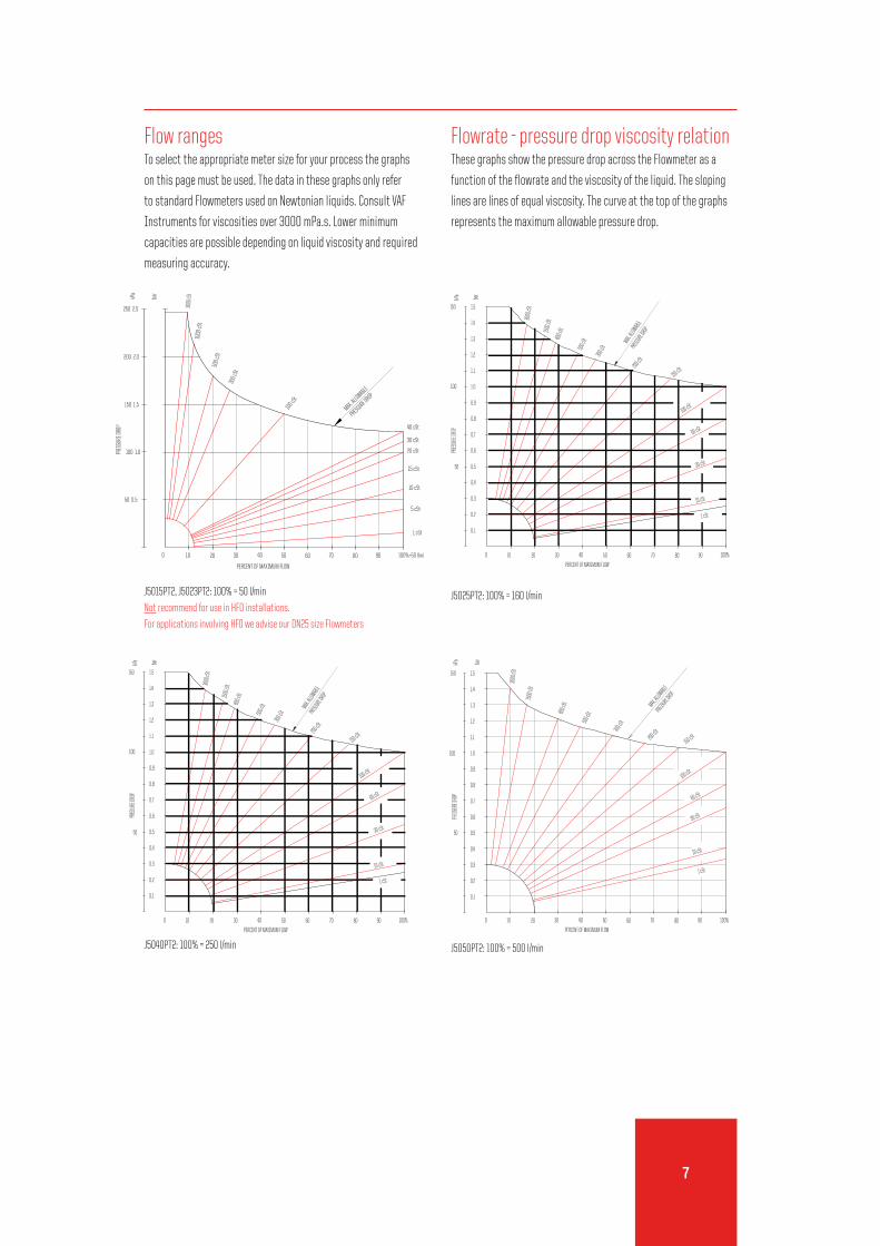
Flow rangesTo select the appropriate meter size for your process the graphs
on this page must be used. The data in these graphs only refer
to standard Flowmeters used on Newtonian liquids. Consult VAF
Instruments for viscosities over 3000 mPa.s. Lower minimum
capacities are possible depending on liquid viscosity and required
measuring accuracy.
Flowrate - pressure drop viscosity relationThese graphs show the pressure drop across the Flowmeter as a
function of the flowrate and the viscosity of the liquid. The sloping
lines are lines of equal viscosity. The curve at the top of the graphs
represents the maximum allowable pressure drop.
80
PRES
SURE
DRO
P
100 1.0
100
50 0.5
PERCENT OF MAXIMUM FLOW
20 4030 6050 70
3000
cSt
150 1.5
200 2.0
250 2.5
kPa
bar
1000
cSt
500
cSt
300 c
St
100 cS
t
20 cSt
90
1 cSt
10 cSt
5 cSt
15 cSt
40 cSt
30 cSt
MAX. ALLOWABLE
PRESSURE DROP
100%=50 l/min
PRES
SURE
DROP
40
PERCENT OF MAXIMUM FLOW
0.3
0.1
0
0.2
50
0.4
0.5
0.6
10 20 30 50 60 70
10 cSt
1 cSt
80 90 100%
30 cSt
500 c
St800 c
St1500
cSt
1.4
100 1.0
0.7
0.8
0.9
1.2
1.1
1.3
150
kPa bar
1.5
3000
cSt
MAX. AL
LOWABL
EPRE
SSURE
DROP
300 c
St
200 cSt
60 cSt
100 cSt
150 cSt
PRES
SURE
DROP
30 cSt0.6
PERCENT OF MAXIMUM FLOW
400
0.2
0.1
50
0.4
0.3
0.5
10 20 30 50 60 70
1 cSt
80 90 100%
10 cSt
500 c
St800 c
St
1500
cSt
100 1.0
0.8
0.7
0.9
1.1
1.3
1.2
150
kPa
1.5
1.4
bar
3000
cSt
MAX. ALL
OWABLEPRESS
URE DROP
200 cSt300 cS
t
60 cSt
100 cSt
150 cSt
J5015PT2, J5023PT2: 100% = 50 l/min
Not recommend for use in HFO installations.
For applications involving HFO we advise our DN25 size Flowmeters
J5040PT2: 100% = 250 l/min
J5025PT2: 100% = 160 l/min
J5050PT2: 100% = 500 l/min
PRES
SURE
DROP
40
PERCENT OF MAXIMUM FLOW
0.3
0.1
0
0.2
50
0.4
0.5
0.6
10 20 30 50 60 70
10 cSt
1 cSt
80 90 100%
30 cSt
500 c
St800 c
St1500
cSt
1.4
100 1.0
0.7
0.8
0.9
1.2
1.1
1.3
150
kPa bar
1.5
3000
cSt
MAX. AL
LOWABL
EPRE
SSURE
DROP
300 c
St
200 cSt
60 cSt
100 cSt
150 cSt
7

1
All c
opyr
ight
s res
erve
d PB-
135-
GB-0
418
Supe
rsed
es PB
-135-
GB-0
816
VAF Instruments B.V.
Vierlinghstraat 24, 3316 EL Dordrecht, The Netherlands
P.O. Box 40, 3300 AA Dordrecht, The Netherlands
T +31 (0) 78 618 3100, [email protected]
Specifications subject to change without notice.
Agents and distributors in more than 50 countries.
Name:
Place and date:
For further information see relevant Product Bulletins
or www.vaf.nl
Represented by
Quotation and ordering informationFor proper selection of the suitable PT2 Flowmeter the following data should be determined:
Liquid data:
1. Process liquid (trade name or chemical composition):
2. Flowrate [l/min] minimum: continuous: maximum:
3. Operating pressure range [bar]: allowable pressure drop [bar]:
4. Operating temperature range [˚C] process liquid: ambient:
5. Viscosity at operating conditions [cSt]:
Flowmeter data:
6. Basic model number:
7. Diameter liquid piping:
8. Wetted parts material: ductile iron
9. Connection flanges: DIN PN [bar] ANSI RF [lbs] JIS [K]
10. Direction to flow: left to right
11. Output pulse output + PT100 (standard)
twin pulse + PT100
twin pulse incl. discriminator + PT 100
12. Liquid filter: required not required
13. Certification: inspection by customer
inspection by classification authority:
factory test and material certificate acc. EN 10204 3.1
other:
14. Tagging: paper tag stn. stl. tag fixed to Flowmeter
15. Monitoring-/ management
solutions and accessories:
FCM2 flow computer
PEM4 Propulsion Efficiency Monitor
IVY® Propulsion Performance Management
Liquid filter