Embed Size (px)
DESCRIPTION
Polimeri cross linked – Termoplastici ed elastomeri con elevate proprietà ottenuti attraverso trattamento con raggi beta o gamma.
Citation preview
PTS-MARKETING IRRADIATION CROSS-LINKING
TECHNOLOGY


I RRAD IAT ION CROSS - L INK ING
Contents
1.) Cross-linking and irradiation cross-linking
2.) Advantages of irradiation cross-linking
3.) Irradiation cross-linked components for industrial control equipment
4.) Polymers for control panels
5.) Insulating materials
6.) Advantages of irradiation cross-linking of V-PTS-CREAMID
7.) Summary
Page
4
4
5
6
9
12
15
1 . ) CROSS - L INK ING AND I RRAD IAT ION CROSS - L INK ING
The cross-linking of rubbers and thermoplastic polymers is a well-proven process for the improve-ment of the thermal properties.
Chemical cross-linking or vulcanization of rubber normally takes place through the effect of heating after processing.
The cross-linking process for thermosets takes place in a similar way. In thermosets the plastic molecules are also chemically linked by heat after processing.
Cross-linked rubbers have a wide-meshed mole-cular network that keeps them soft and their properties change only slightly over a wide tempe-rature range.
Thermosets on the other hand are characterized by a very narrow-meshed network. Due to this fact they hardly change their high level of stiffness over a wide temperature range.
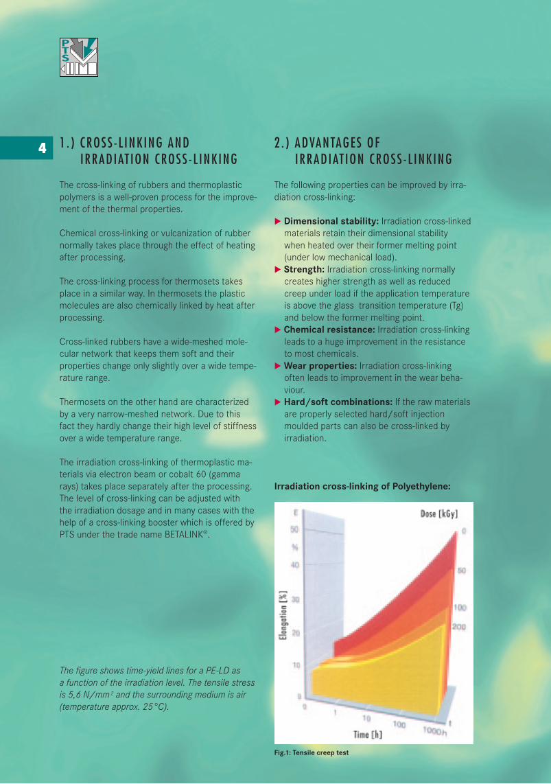
The irradiation cross-linking of thermoplastic ma-terials via electron beam or cobalt 60 (gamma rays) takes place separately after the processing. The level of cross-linking can be adjusted with the irradiation dosage and in many cases with the help of a cross-linking booster which is offered by PTS under the trade name BETALINK®.
The figure shows time-yield lines for a PE-LD as a function of the irradiation level. The tensile stress is 5,6 N/mm 2 and the surrounding medium is air (temperature approx. 25°C).
2 . ) ADVANTAGES OF I RRAD IAT ION CROSS - L INK ING
The following properties can be improved by irra-diation cross-linking:
u Dimensional stability: Irradiation cross-linked materials retain their dimensional stability when heated over their former melting point (under low mechanical load).u Strength: Irradiation cross-linking normally creates higher strength as well as reduced creep under load if the application temperature is above the glass transition temperature (Tg) and below the former melting point.u Chemical resistance: Irradiation cross-linking leads to a huge improvement in the resistance to most chemicals.uWear properties: Irradiation cross-linking often leads to improvement in the wear beha- viour.u Hard/soft combinations: If the raw materials are properly selected hard/soft injection moulded parts can also be cross-linked by irradiation.
Irradiation cross-linking of Polyethylene:
Fig.1: Tensile creep test
4
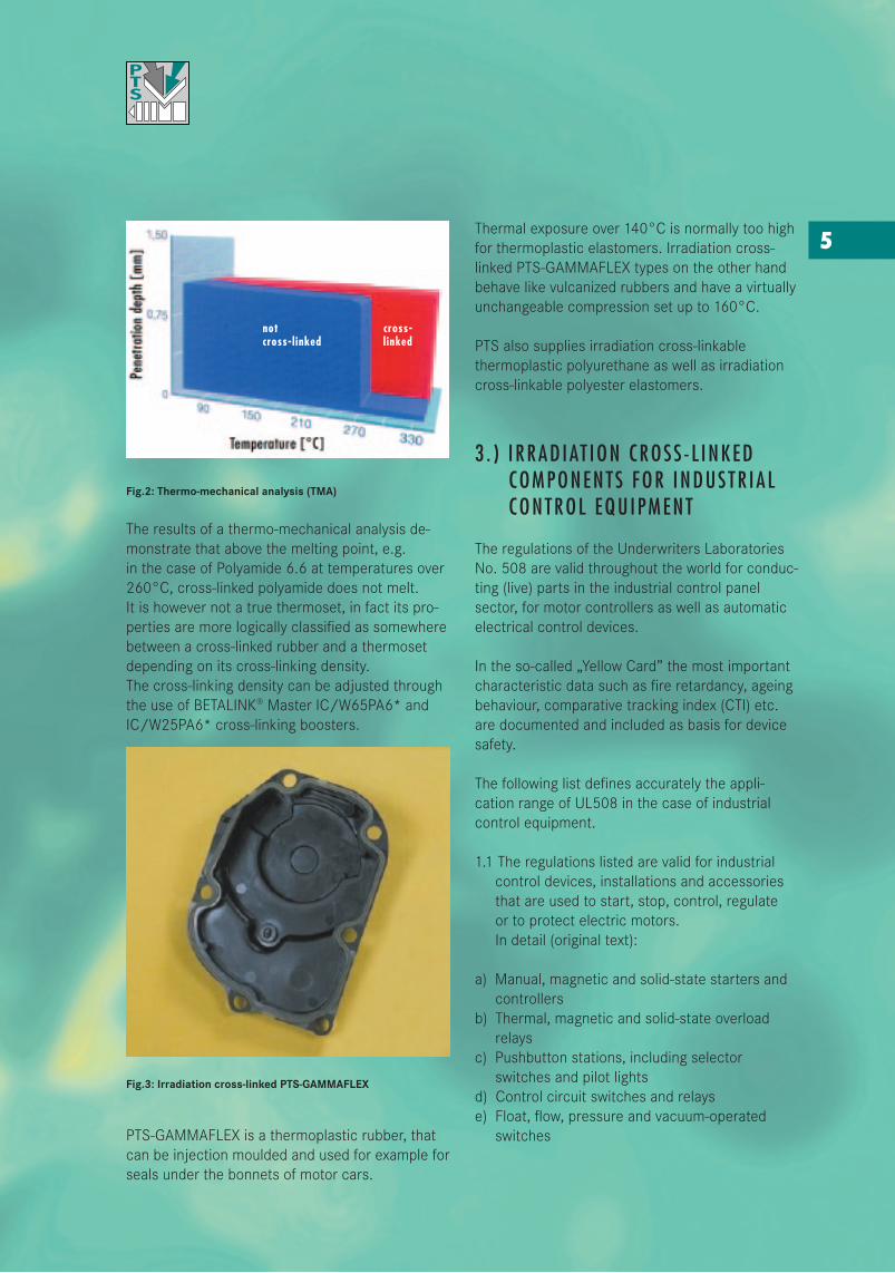
Fig.2: Thermo-mechanical analysis (TMA)
The results of a thermo-mechanical analysis de-monstrate that above the melting point, e.g. in the case of Polyamide 6.6 at temperatures over 260°C, cross-linked polyamide does not melt. It is however not a true thermoset, in fact its pro-perties are more logically classified as somewhere between a cross-linked rubber and a thermoset depending on its cross-linking density. The cross-linking density can be adjusted through the use of BETALINK® Master IC/W65PA6* and IC/W25PA6* cross-linking boosters.
Fig.3: Irradiation cross-linked PTS-GAMMAFLEX
PTS-GAMMAFLEX is a thermoplastic rubber, that can be injection moulded and used for example for seals under the bonnets of motor cars.
Thermal exposure over 140°C is normally too high for thermoplastic elastomers. Irradiation cross-linked PTS-GAMMAFLEX types on the other hand behave like vulcanized rubbers and have a virtually unchangeable compression set up to 160°C.
PTS also supplies irradiation cross-linkable thermoplastic polyurethane as well as irradiationcross-linkable polyester elastomers.
3 . ) I RRAD IAT ION CROSS - L INKED COMPONENTS FOR INDUSTR IAL CONTROL EQU IPMENT
The regulations of the Underwriters Laboratories No. 508 are valid throughout the world for conduc-ting (live) parts in the industrial control panel sector, for motor controllers as well as automatic electrical control devices.
In the so-called „Yellow Card” the most important characteristic data such as fire retardancy, ageing behaviour, comparative tracking index (CTI) etc. are documented and included as basis for device safety.
The following list defines accurately the appli-cation range of UL508 in the case of industrial control equipment.
1.1 The regulations listed are valid for industrial control devices, installations and accessories that are used to start, stop, control, regulate or to protect electric motors. In detail (original text):
a) Manual, magnetic and solid-state starters and controllersb) Thermal, magnetic and solid-state overload relaysc) Pushbutton stations, including selector switches and pilot lightsd) Control circuit switches and relayse) Float, flow, pressure and vacuum-operated switches
5
not cross-cross-linked linked
f) Resistors and rheostatsg) Proximity switchesh) Time-delay relays and switchesi) Resistors and rheostats intended for industrial heating and lighting, including those for motor generator fieldsj) Control devices intended for industrial heating and lightingk) Solid-state time-delay relaysl) Programmable controllersm) Numerical control systemsn) Lighting dimmer systems and controlso) Mercury-tube switchesp) Definite purpose controllers
1.2 These regulations concern devices up to 1500 V which are operated in ambient tempe- ratures of from 0°C to 40°C.
1.3 The regulations also apply to industrial control panels which are installed in control devices for motor-operated industrial equipment. Examples are industrial switchgears, control- lers, installations, interrupters, temperature monitors, motor protection devices and electri- cal instruments.
A specification is established in UL508 for polymers in which the individual test criteria are accurately defined.
4 . ) POLYMERS FOR CONTROL PANELS
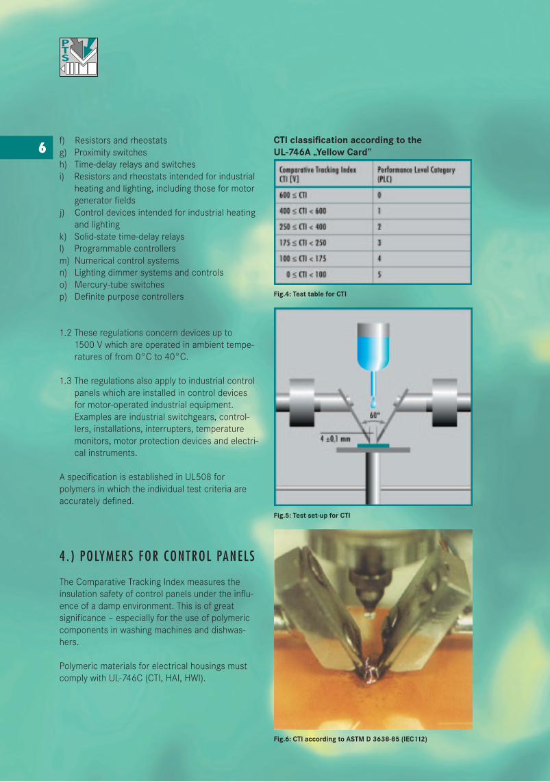
The Comparative Tracking Index measures the insulation safety of control panels under the influ-ence of a damp environment. This is of great significance – especially for the use of polymeric components in washing machines and dishwas-hers.
Polymeric materials for electrical housings must comply with UL-746C (CTI, HAI, HWI).
CTI classification according to the UL-746A „Yellow Card”
Fig.4: Test table for CTI
Fig.5: Test set-up for CTI
Fig.6: CTI according to ASTM D 3638-85 (IEC112)
6
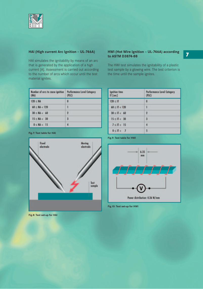
HAI (High current Arc Ignition – UL-746A)
HAI simulates the ignitability by means of an arc that is generated by the application of a high current [A]. Assessment is carried out according to the number of arcs which occur until the test material ignites.
Fig.7: Test table for HAI
Fig.8: Test set-up for HAI
HWI (Hot Wire Ignition – UL-746A) according to ASTM D3874-88
The HWI test simulates the ignitability of a plastic test sample by a glowing wire. The test criterion is the time until the sample ignites.
Fig.9: Test table for HWI
Fig.10: Test set-up for HWI
7
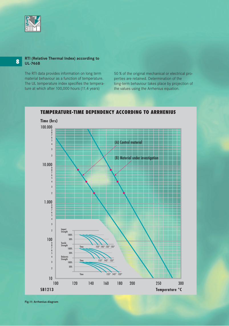
RTI (Relative Thermal Index) according to UL-746B
The RTI data provides information on long term material behaviour as a function of temperature. The UL temperature index specifies the tempera-ture at which after 100,000 hours (11.4 years)
Fig.11: Arrhenius diagram
50 % of the original mechanical or electrical pro-perties are retained. Determination of the long-term behaviour takes place by projection of the values using the Arrhenius equation.
8
TEMPERATURE-TIME DEPENDENCY ACCORDING TO ARRHENIUS
100.000Time (hrs)
9
4
65
3
7
2
8
9
4
65
3
7
2
8
9
4
65
3
7
2
8
9
4
65
3
7
2
8
10.000
1.000
100
10100 120 140 160 180 200 250 300
SB1213
(A) Control material
(B) Material under investigation
Time 155ϒ 145ϒ 135ϒ 125ϒ
Time 155ϒ 145ϒ 135ϒ
Time 155ϒ 145ϒ 135ϒ
ImpactStrength
TensileStrength
DielectricStrength
100%
50%
50%
50%
100%
100%
ImpactStrength
TensileStrength
DielectricStrength
100%
50%
50%
50%
100%
100%
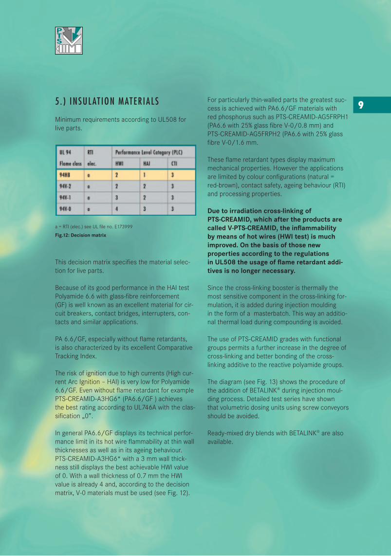
5 . ) INSULAT ION MATER IALS
Minimum requirements according to UL508 for live parts.
a = RTI (elec.) see UL file no. E173999
Fig.12: Decision matrix
This decision matrix specifies the material selec-tion for live parts.
Because of its good performance in the HAI test Polyamide 6.6 with glass-fibre reinforcement (GF) is well known as an excellent material for cir-cuit breakers, contact bridges, interrupters, con-tacts and similar applications.
PA 6.6/GF, especially without flame retardants, is also characterized by its excellent Comparative Tracking Index.
The risk of ignition due to high currents (High cur-rent Arc Ignition – HAI) is very low for Polyamide 6.6/GF. Even without flame retardant for example PTS-CREAMID-A3HG6* (PA6.6/GF ) achieves the best rating according to UL746A with the clas-sification „0”.
In general PA6.6/GF displays its technical perfor-mance limit in its hot wire flammability at thin wall thicknesses as well as in its ageing behaviour. PTS-CREAMID-A3HG6* with a 3 mm wall thick-ness still displays the best achievable HWI value of 0. With a wall thickness of 0.7 mm the HWI value is already 4 and, according to the decision matrix, V-0 materials must be used (see Fig. 12).
For particularly thin-walled parts the greatest suc-cess is achieved with PA6.6/GF materials with red phosphorus such as PTS-CREAMID-AG5FRPH1 (PA6.6 with 25% glass fibre V-0/0.8 mm) and PTS-CREAMID-AG5FRPH2 (PA6.6 with 25% glass fibre V-0/1.6 mm.
These flame retardant types display maximum mechanical properties. However the applications are limited by colour configurations (natural = red-brown), contact safety, ageing behaviour (RTI) and processing properties.
Due to irradiation cross-linking of PTS-CREAMID, which after the products are called V-PTS-CREAMID, the inflammability by means of hot wires (HWI test) is much improved. On the basis of those new properties according to the regulations in UL508 the usage of flame retardant addi-tives is no longer necessary.
Since the cross-linking booster is thermally the most sensitive component in the cross-linking for-mulation, it is added during injection moulding in the form of a masterbatch. This way an additio-nal thermal load during compounding is avoided.
The use of PTS-CREAMID grades with functional groups permits a further increase in the degree of cross-linking and better bonding of the cross-linking additive to the reactive polyamide groups.
The diagram (see Fig. 13) shows the procedure of the addition of BETALINK® during injection moul-ding process. Detailed test series have shown that volumetric dosing units using screw conveyors should be avoided.
Ready-mixed dry blends with BETALINK® are also available.
9
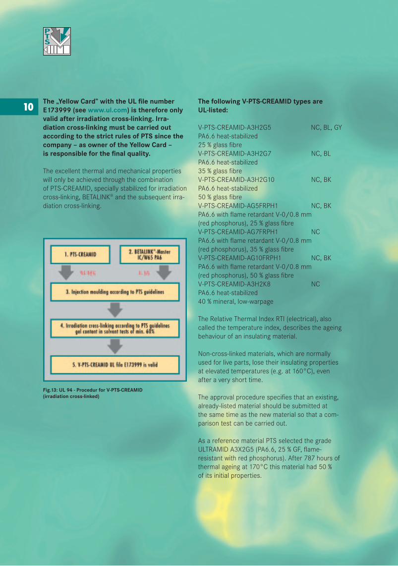
10The „Yellow Card” with the UL file number E173999 (see www.ul.com) is therefore only valid after irradiation cross-linking. Irra-diation cross-linking must be carried out according to the strict rules of PTS since the company – as owner of the Yellow Card – is responsible for the final quality.
The excellent thermal and mechanical properties will only be achieved through the combination of PTS-CREAMID, specially stabilized for irradiation cross-linking, BETALINK® and the subsequent irra-diation cross-linking.
Fig.13: UL 94 - Procedur for V-PTS-CREAMID (irradiation cross-linked)
The following V-PTS-CREAMID types are UL-listed:
V-PTS-CREAMID-A3H2G5 NC, BL, GYPA6.6 heat-stabilized25 % glass fibreV-PTS-CREAMID-A3H2G7 NC, BLPA6.6 heat-stabilized35 % glass fibreV-PTS-CREAMID-A3H2G10 NC, BKPA6.6 heat-stabilized50 % glass fibreV-PTS-CREAMID-AG5FRPH1 NC, BKPA6.6 with flame retardant V-0/0.8 mm(red phosphorus), 25 % glass fibreV-PTS-CREAMID-AG7FRPH1 NCPA6.6 with flame retardant V-0/0.8 mm(red phosphorus), 35 % glass fibreV-PTS-CREAMID-AG10FRPH1 NC, BKPA6.6 with flame retardant V-0/0.8 mm(red phosphorus), 50 % glass fibreV-PTS-CREAMID-A3H2K8 NCPA6.6 heat-stabilized40 % mineral, low-warpage
The Relative Thermal Index RTI (electrical), also called the temperature index, describes the ageing behaviour of an insulating material.
Non-cross-linked materials, which are normally used for live parts, lose their insulating properties at elevated temperatures (e.g. at 160°C), even after a very short time.
The approval procedure specifies that an existing, already-listed material should be submitted at the same time as the new material so that a com-parison test can be carried out.
As a reference material PTS selected the grade ULTRAMID A3X2G5 (PA6.6, 25 % GF, flame-resistant with red phosphorus). After 787 hours of thermal ageing at 170°C this material had 50 % of its initial properties.
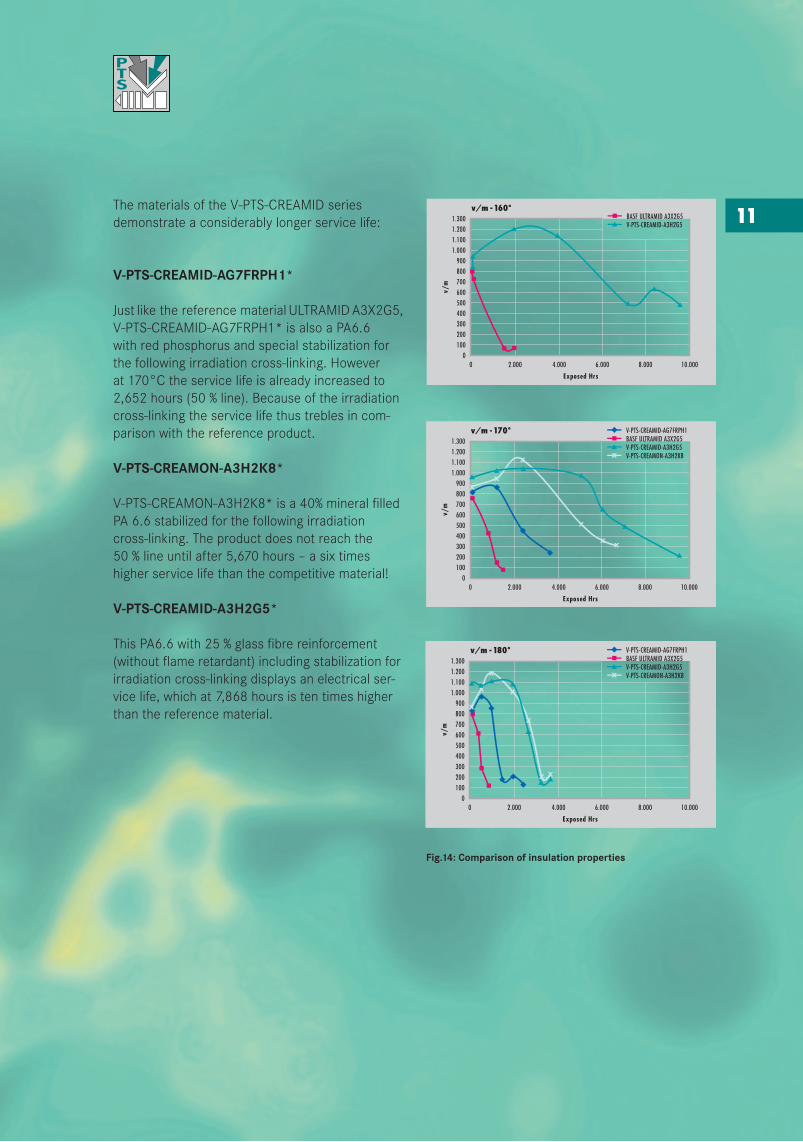
11The materials of the V-PTS-CREAMID series demonstrate a considerably longer service life:
V-PTS-CREAMID-AG7FRPH1*
Just like the reference material ULTRAMID A3X2G5, V-PTS-CREAMID-AG7FRPH1* is also a PA6.6 with red phosphorus and special stabilization for the following irradiation cross-linking. However at 170°C the service life is already increased to 2,652 hours (50 % line). Because of the irradiation cross-linking the service life thus trebles in com-parison with the reference product.
V-PTS-CREAMON-A3H2K8*
V-PTS-CREAMON-A3H2K8* is a 40% mineral filled PA 6.6 stabilized for the following irradiation cross-linking. The product does not reach the 50 % line until after 5,670 hours – a six times higher service life than the competitive material!
V-PTS-CREAMID-A3H2G5*
This PA6.6 with 25 % glass fibre reinforcement (without flame retardant) including stabilization for irradiation cross-linking displays an electrical ser-vice life, which at 7,868 hours is ten times higher than the reference material.
Fig.14: Comparison of insulation properties
Exposed Hrs
1.300 BASF ULTRAMID A3X2G5V-PTS-CREAMID-A3H2G5
1.2001.1001.000
900800700600500400300200100
010.0008.0006.0004.0002.0000
v/m
————
Exposed Hrs
1.300
V-PTS-CREAMID-AG7FRPH1BASF ULTRAMID A3X2G5V-PTS-CREAMID-A3H2G5V-PTS-CREAMON-A3H2K81.200
1.1001.000
900800700600500400300200100
010.0008.0006.0004.0002.0000
v/m
————————
Exposed Hrs
1.300
V-PTS-CREAMID-AG7FRPH1BASF ULTRAMID A3X2G5V-PTS-CREAMID-A3H2G5V-PTS-CREAMON-A3H2K81.200
1.1001.000
900800700600500400300200100
010.0008.0006.0004.0002.0000
v/m
————————
12
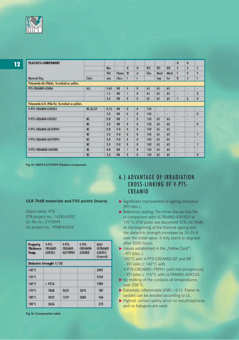
Fig.15: QMFZ2.E173999 Plastics component
ULB 746B materials and F50 points (hours)
Client name: PTSSTR project no.: 14740-0002UL file no.: E173999UL project no.: 99ME46256
Fig.16: Comparative table
6 . ) ADVANTAGE OF IRRAD IAT ION CROSS - L INK ING 0F V-P TS - CREAMID
u Significant improvement in ageing behaviour (RTI elec.).u Reference testing: Ten times the service life in comparison with ULTRAMID-A3X2G5 at 170°C (F50 point see document STR/UL746B). At the beginning of the thermal ageing test the dielectric strength increases by 20-25 % over the initial value. It only starts to degrade after 5000 hours.u Values established in the „Yellow Card”: - RTI (elec.): 150°C with V-PTS-CREAMID-GF and MF – RTI (elec.): 140°C with V-PTS-CREAMID- FRPH1 (with red phosphorus) – RTI (elec.): 115°C with ULTRAMID-A3X2G5u No melting of the contacts at temperatures over 258°C.u Extremely inflammable (HWI = 0-1). Flame re- tardant can be avoided according to UL.u Highest contact safety since no red phosphorus and no halogens are used.
13u No restrictions of coloursu Minimum smoke and low toxicity in the event of fireu Lead-free soldering technology with tempera- tures of up to 280°C can be used without prob- lems. In many cases liquid-crystal polymers (LCP) and thermosets can be replaced.
Soldering using the high-temperature processes (0.5 sec. at 450-500°C) is possible, e.g. for the manufacture of small coils.
u With a component wall thickness of 1.6 to 2 mm the hot wire test according to IEC 695-2-1 was successfully passed at 750, 850 and 960°C.
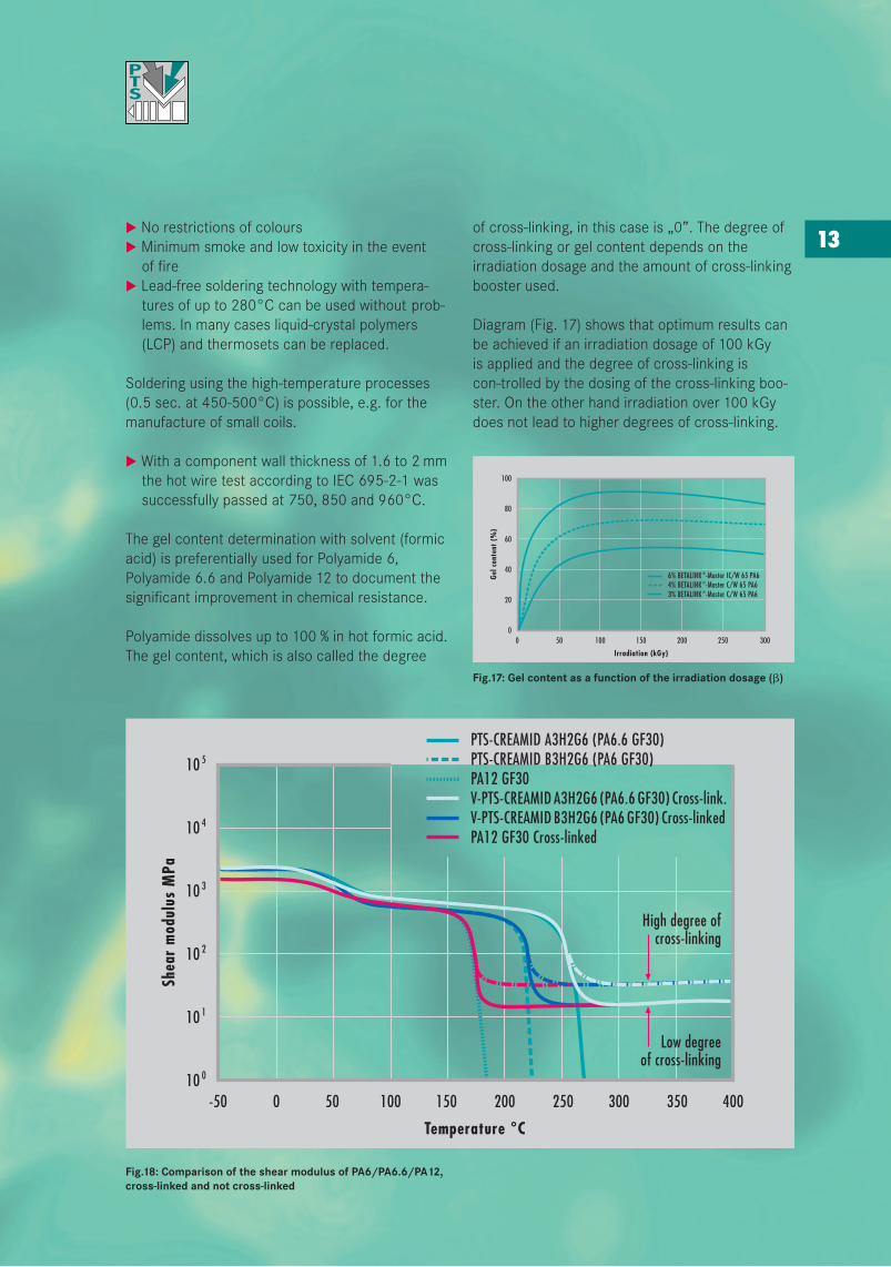
The gel content determination with solvent (formic acid) is preferentially used for Polyamide 6, Polyamide 6.6 and Polyamide 12 to document the significant improvement in chemical resistance.
Polyamide dissolves up to 100 % in hot formic acid. The gel content, which is also called the degree
Fig.18: Comparison of the shear modulus of PA6/PA6.6/PA12, cross-linked and not cross-linked
of cross-linking, in this case is „0”. The degree of cross-linking or gel content depends on the irradiation dosage and the amount of cross-linking booster used.
Diagram (Fig. 17) shows that optimum results can be achieved if an irradiation dosage of 100 kGy is applied and the degree of cross-linking iscon-trolled by the dosing of the cross-linking boo-ster. On the other hand irradiation over 100 kGy does not lead to higher degrees of cross-linking.
Fig.17: Gel content as a function of the irradiation dosage ( )
Irradiation (kGy)
100
250
Gel c
onte
nt (
%)
300200150100500
80
60
40
20
0
6% BETALINK ®-Master IC/W 65 PA64% BETALINK ®-Master C/W 65 PA63% BETALINK ®-Master C/W 65 PA6
10 5
350
Shea
r m
odul
us M
Pa
400300250200500
10 4
10 3
10 2
10 1
10 0
150100-50
Low degreeof cross-linking
High degree ofcross-linking
PTS-CREAMID A3H2G6 (PA6.6 GF30)PTS-CREAMID B3H2G6 (PA6 GF30)PA12 GF30V-PTS-CREAMID A3H2G6 (PA6.6 GF30) Cross-link.V-PTS-CREAMID B3H2G6 (PA6 GF30) Cross-linkedPA12 GF30 Cross-linked
14The shear modulus graph of V-PTS-CREAMID-A3H2G6 shows that at 258°C there is still suffici-ent residual rigidity, and this doesn’t change any more until the product is thermally decomposed. In the temperature range between 222°C and 260°C irradiation cross-linked V-PTS-CREAMID-A (PA6.6) has significantly higher strength compa-red to irradiation cross-linked V-PTS-CREAMID-B (PA6) and PA12.
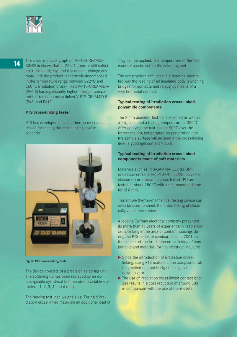
PTS cross-linking tester
PTS has developed a simple thermo-mechanical device for testing the cross-linking level in seconds.
Fig.19: PTS cross-linking tester
The device consists of a precision soldering unit. The soldering tip has been replaced by an ex-changeable cylindrical test mandrel (available dia-meters: 1, 2, 3, 4 and 6 mm).
The moving test load weighs 1 kg. For rigid irra-diation cross-linked materials an additional load of
1 kg can be applied. The temperature of the test mandrel can be set on the soldering unit.
The construction simulates in a practice-orienta-ted way the loading of an insulated body (switching bridges for contacts and relays) by means of a very hot metal contact.
Typical testing of irradiation cross-linked polyamide components
The 2 mm diameter test tip is selected as well as a 1 kg load and a testing temperature of 350°C. After applying the test load at 90°C over the former melting temperature no penetration into the sample surface will be seen if the cross-linking level is good (gel content > 65%).
Typical testing of irradiation cross-linked components made of soft materials
Materials such as PTS-GAMMAFLEX (EPDM), irradiation cross-linked PTS-UNIFLEX-E (polyester elastomer) or irradiation cross-linked TPU are tested at about 250°C with a test mandrel diame-ter of 6 mm.
This simple thermo-mechanical testing device can even be used to check the cross-linking of classi-cally vulcanized rubbers.
A leading German electrical company presented its more than 15 years of experience in irradiation cross-linking in the area of contact housings du-ring the PTS series of seminars held in 2001 on the subject of the irradiation cross-linking of com-ponents and materials for the electrical industry:
u Since the introduction of irradiation cross- linking, using PTS materials, the complaints rate for „melted contact bridges” has gone down to zero.u The use of irradiation cross-linked contact brid- ges results in a cost reduction of around 30% in comparison with the use of thermosets.
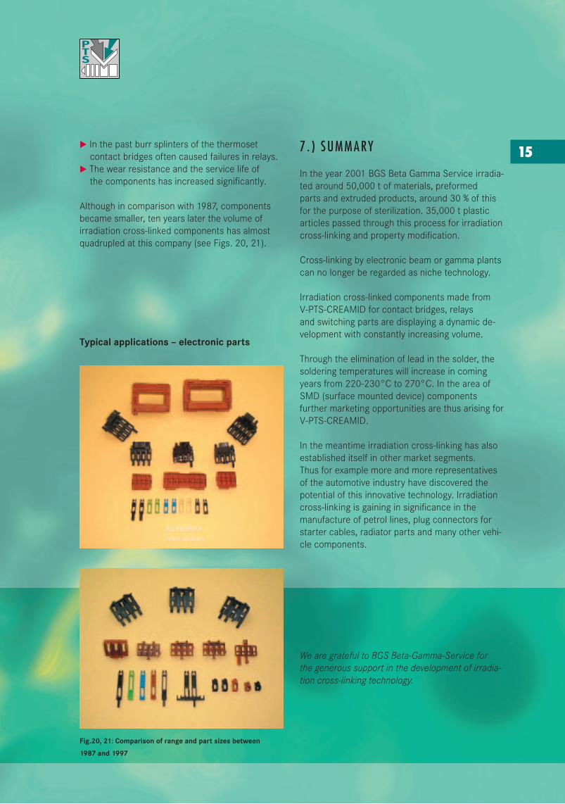
15u In the past burr splinters of the thermoset contact bridges often caused failures in relays.u The wear resistance and the service life of the components has increased significantly.
Although in comparison with 1987, components became smaller, ten years later the volume of irradiation cross-linked components has almost quadrupled at this company (see Figs. 20, 21).
Typical applications – electronic parts
Fig.20, 21: Comparison of range and part sizes between
1987 and 1997
7 . ) SUMMARY
In the year 2001 BGS Beta Gamma Service irradia-ted around 50,000 t of materials, preformed parts and extruded products, around 30 % of this for the purpose of sterilization. 35,000 t plastic articles passed through this process for irradiation cross-linking and property modification.
Cross-linking by electronic beam or gamma plants can no longer be regarded as niche technology.
Irradiation cross-linked components made from V-PTS-CREAMID for contact bridges, relays and switching parts are displaying a dynamic de-velopment with constantly increasing volume.
Through the elimination of lead in the solder, the soldering temperatures will increase in coming years from 220-230°C to 270°C. In the area of SMD (surface mounted device) components further marketing opportunities are thus arising for V-PTS-CREAMID.
In the meantime irradiation cross-linking has also established itself in other market segments. Thus for example more and more representatives of the automotive industry have discovered the potential of this innovative technology. Irradiation cross-linking is gaining in significance in the manufacture of petrol lines, plug connectors for starter cables, radiator parts and many other vehi-cle components.
We are grateful to BGS Beta-Gamma-Service for the generous support in the development of irradia-tion cross-linking technology.

Rothenburg o.d.T.
PTS Plastic Technologie ServiceMarketing- & Vertriebs-GmbHHautschenmühle 3D-91587 AdelshofenPhone +49-(0)9865-821Fax +49-(0)[email protected]
Concept, editing,graphics and production:Pia Seifried, Hans-Peter Singer
Printed by: Druck+Papier Meyer
January 2003 MEDIUM OF THE PTS-GROUP: PTS-MARKETING, PTS-COMPOUND, CPP-CREATIVE-POLYMERS-PRODUKTION


![[MS-PST]: Outlook Personal Folders (.pst) File Format · 2019-03-21 · [MS-PST]: Outlook Personal Folders (.pst) File Format Intellectual Property Rights Notice for Open Specifications](https://img.pdfslide.us/doc/110x75/5eccceeec221095fc21e2a35/ms-pst-outlook-personal-folders-pst-file-format-2019-03-21-ms-pst-outlook.jpg)
![[MS-PST]: Outlook Personal Folders (.pst) File Format · 2016-09-14 · [MS-PST]: Outlook Personal Folders (.pst) File Format Intellectual Property Rights Notice for Open Specifications](https://img.pdfslide.us/doc/110x75/5f6c9e9b4e11ae13a90bf845/ms-pst-outlook-personal-folders-pst-file-format-2016-09-14-ms-pst-outlook.jpg)


![[MS-PST]: Outlook Personal Folders (.pst) File Format - Microsoft](https://img.pdfslide.us/doc/110x75/613c7b43c957d930775e4106/ms-pst-outlook-personal-folders-pst-file-format-microsoft.jpg)


![interoperability.blob.core.windows.netMS-PST] … · Web view[MS-PST]: Outlook Personal Folders (.pst) File Format. Intellectual Property Rights Notice for Open Specifications Documentation](https://img.pdfslide.us/doc/110x75/5ebfeca962f8b411ae1e5d4e/ms-pst-web-view-ms-pst-outlook-personal-folders-pst-file-format-intellectual.jpg)