Embed Size (px)
Citation preview

CanonCanonCanonCanon
SERVICE SUPPORT TOOL
Version 1.41Eh
USER MANUAL
Documentation developed byCanon U.S.A., Inc.
Imaging Systems GroupSystems and Technical Support Division
Hardware EngineeringRevision 11 - April 30, 2002


Service Support Tool User Manual
TABLE OF CONTENTS
Revision History ...................................................................................................................ii1 - Uninstalling the Service Support Tool..........................................................................1-12 - Introduction and Description ........................................................................................2-13 - Installation Specifications ............................................................................................3-14 - Installation/Setup Instructions ......................................................................................4-15 - Starting the Service Support Tool.................................................................................5-16 - Features and Functions .................................................................................................6-1
6A - Controlling Data .........................................................................................6A-1Registering Firmware/Software ..............................................................6A-3Removing Firmware/Software................................................................6A-6Controlling Backup Data ........................................................................6A-8
6B - Downloading/Uploading Data .................................................................... 6B-16B1 - FDIMM....................................................................................... 6B1-1
Firmware Downloading ............................................................ 6B1-5Backup Data Uploading............................................................ 6B1-9Backup Data Downloading ..................................................... 6B1-13
6B2 - BootROM.................................................................................... 6B2-16B3 - HD Format .................................................................................. 6B3-16B4 - System Software ......................................................................... 6B4-1
Updating System Software ....................................................... 6B4-6Restoring Backup System Software ....................................... 6B4-10Uploading Backup Data.......................................................... 6B4-12Downloading Backup Data ..................................................... 6B4-15
6B5 - RUI.............................................................................................. 6B5-16B6 - Language..................................................................................... 6B6-16B7 - Serial Downloading using the Downloader PCB ....................... 6B7-16B8 - G3 Fax......................................................................................... 6B8-1
7 - Device Specific Notes ..................................................................................................7-1
Table of Contents/Revision History : i

Service Support Tool User Manual
Revision History:
Original: Introduction of Service Support Tool v1.01ERev 2: Added FAQ Section at end of Doc. 4/15/99Rev 3: Introduction of Service Support Tool v1.02E 5/17/99
Added Text describing RAM backup FunctionAdded RAM backup function InstructionsUpdated Document IntroductionAdded Screen CapturesAdded Info on how to Uninstall the Service Support Tool
Rev 4: Introduction of Service Support Tool v1.14Ea 8/31/00Content revised and updatedInformation added on new Download ModesInformation added on new software file types supportedDevice Specific Notes added
Rev 5: Completed RUI Download section 11/22/00Content revised and updatedInformation added on Network flashing for iR3250
Rev 6: Introduction of Service Support Tool v1.25Ee 5/3/01Updated content to reflect Windows NT/2000 support and limitations
Content revised and updatedNew models supported(imageRUNNER 8500, Color imageRUNNER C2050, CLC 5000)File types and supported download modesHD Format section revisedFAQ section removed – content is now included in other sectionsUninstallation/Installation sections expanded
Rev 7: Content revised and updated 5/15/01New models supported(imageRUNNER 2200/2800/3300)File types supported – G3 Fax added
Rev 8: Introduction of Service Support Tool v1.31Eg 9/21/01NOTE: Screenshots remain predominantly from v1.25E – theonly major difference between v1.25E and v1.31E screenshots isthe version number indicated in the window’s title bar.Support added for flashing Copier version System Software on unitswith Network BootROMs – for units that support imagePASScontrollers ONLYImprovements in Uploading/Downloading backup data to GP/iR/CLC unitsLast used interface will be remembered (Parallel/Network)
Content revised and updatedNew models supported(imageRUNNER 5000 – new Main Controller, imageRUNNER 6000, imageRUNNER 5000i, imageRUNNER 105)
ii : Table of Contents/Revision History
Service Support Tool User Manual
Rev 9: Introduction of Service Support Tool v1.32Eg 10/5/01NOTE: Screenshots remain predominantly from v1.25E – theonly major difference between v1.25E and v1.32E screenshots isthe version number indicated in the window’s title bar.A typographical error was corrected in some windows.
Rev 10: Content revised and updated 3/12/02New models supported(imageRUNNER 7200, imageRUNNER 85, Color imageRUNNER C2058)
Rev 11: Introduction of Service Support Tool v1.41Eh 4/30/02NOTE: Screenshots remain predominantly from v1.25E – theonly major difference between v1.25E and v1.41E screenshots isthe version number indicated in the window’s title bar.
Content revised and updatedNew models supported(imageRUNNER 1600/2000, imageRUNNER 400S, imageRUNNER 3300i)Information added on new Download Mode - USBInformation added on USB Driver and Windows 98 issuesPC requirements updatedExtra installation steps for USB (Windows 98) added
Table of Contents/Revision History : iii

Service Support Tool User Manual
iv : Table of Contents/Revision History

Service Support Tool User Manual
1 - Uninstalling the Service Support Tool:
Earlier versions of the Service Support Tool should be removed from the PC prior to installing anupdated version. The Service Support Tool can be uninstalled from the PC via the Add\RemovePrograms Option in Windows 9.x/NT/2000 as follows:
1. Double click on the My Computer icon.2. Double click on the Control Panel icon.3. Double click on Add\Remove Programs.4. Scroll down to Service Support Tool.5. Highlight it and click Remove.
NOTE: All folders under C:\ServTool\ - including the NewRom folder - remain.
Once Remove is clicked, the following confirmation screen will be displayed:
Click on Yes to remove the Service Support Tool. A warning will be shown indicating that ashared file will be removed. This is shown below:
Uninstalling the Service Support Tool : 1-1
Service Support Tool User Manual
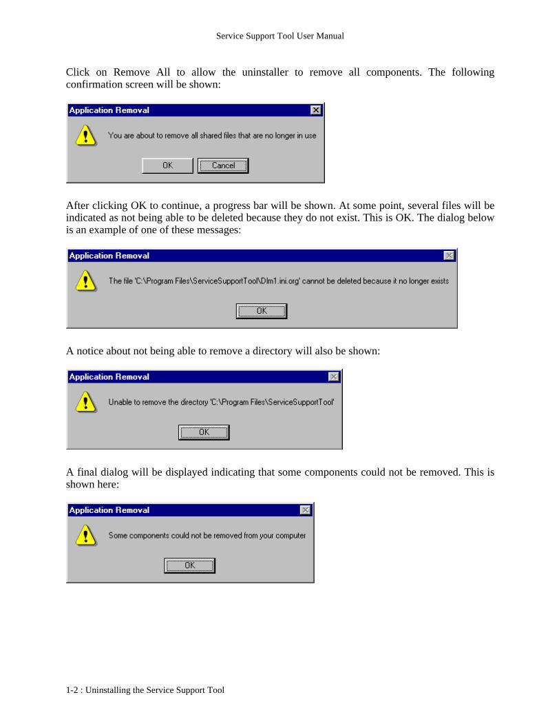
Click on Remove All to allow the uninstaller to remove all components. The followingconfirmation screen will be shown:
After clicking OK to continue, a progress bar will be shown. At some point, several files will beindicated as not being able to be deleted because they do not exist. This is OK. The dialog belowis an example of one of these messages:
A notice about not being able to remove a directory will also be shown:
A final dialog will be displayed indicating that some components could not be removed. This isshown here:
1-2 : Uninstalling the Service Support Tool
Service Support Tool User Manual
2 - Introduction and Description:
The Service Support Tool provides a graphical interface between the PC and the copier. Itprovides two main functions:
• Flash upgrade FDIMM firmware, BootROM, System Software, RUI, Language, G3 Fax and format the HD in Canon copiers (not all items possible with all machines)
• Backup\Restore RAM data
NOTE : Please refer to the Device Specific Notes section for details on how the Service SupportTool interacts with the different machines supported.
Flash Upgrade FunctionThe current and future line of both Canon Digital B&W and Color Laser Copiers will containFlash Dual In-Line Memory Modules (FDIMMs). Each of these modules (number, function, andlocation depends on the particular copier model) contain firmware providing machine specificfunctions and instructions. As such, each module can be updated in the field using the ServiceSupport Tool as bug fixes and or new features are added to the copier. Upgrading the modules isknown as Flashing.
Additionally, certain models will have the functionality of being able to also have the BootROMsflashed with this tool as well as downloading System Software, the RUI and Language Files to aHard Drive. Some models will also need this tool to perform HD formatting on new, blank,service part Hard Drives.
Backup/Restore Ram DataEach copier is adjusted at the factory, and its adjustment values are recorded on the service label.If replacing any PCBs with FDIMMs attached or initializing RAM, the corresponding values willbe affected. Using the Service Support Tool a backup file can be created and saved on the PC.Once the PCB has been replaced, the RAM backup file can then be restored to the copier, and itsfactory setting restored. Various other user settings stored on these PCBs may also be backed upand restored when required. Note: It is unnecessary to backup\restore RAM data when upgradingFirmware.
Obtaining Software FilesSoftware files may be available by different means, such as e-Support or CD.
From e-Support, files will be collected into a self-extracting data file. This data file will need to beexpanded. The default location for this expansion is the C:\ServTool\NewRom folder.
If downloading more than one data file, DO NOT EXTRACT ALL OF THE DATA FILES ATONCE. Extract one data file set (which will now be in the NewRom folder), register that data,then proceed with the next file.
Please refer to the Device Specific Notes section for the number and extensions of files for eachmachine and data type.
Introduction and Description : 2-1

Service Support Tool User Manual
2-2 : Introduction and Description

Service Support Tool User Manual
3 - Installation Specifications:
Minimum PC Requirements for Installation of Service Support Tool:
1. Pentium 166 Mhz or higher2. 16 MB of RAM3. 20 MB of hard disk space4. Monitor resolution: VGA (640x480)5. 16 Bit Color6. Printer port: Bi-centronics (IEEE 1284) ECP mode7. Network Connection (Ethernet - RJ45)8. USB port9. CD-ROM Drive10. Windows 95/98/NT4/2000 Operating System
Recommended:
RAM : 32 MB or more
Necessary Cables:
1. IEEE1284 Parallel Cable2. Cross-Over Ethernet Cable3. USB Cable (Type A to Type B)
NOTE : High-Speed Parallel Mode is NOT available under Windows NT or 2000 – even ifsupported by the hardware. Under these Operating Systems, the only Parallel Mode supported isLow-Speed.
Installation Specifications : 3-1

Service Support Tool User Manual
3-2 : Installation Specifications
Service Support Tool User Manual
4 - Installation/Setup Instructions:
Starting with version 1.41 of the Service Support Tool, there are now two installer packagesavailable. One is the same as in previous versions and the other is targeted for Windows 98. Thereason behind this is the third party USB driver that is included. For certain machines (such as theimageRUNNER 2000), certain components will need to be flashed via USB. The standard USBPrint driver that comes with Windows 98 (1st or 2nd editions) was not acceptable for use with theService Support Tool. The USB Print driver of Windows 2000 was acceptable. To allow flashingvia USB under Windows 98, Canon has licensed and included a third party USB driver. Underterms of the third party license, Canon must track the whereabouts of all instances of this driver.Upon contract termination with the third party, all instances of the driver MUST be deleted.
To enable the proper tracking (so that notification may be sent out when deletion is required),Canon will NOT post the version of the Service Support Tool with the USB driver to e-Support.The only way to receive this version is by CD distribution (i.e. System Software CD distributionfor the imageRUNNER 1600/2000). CDs distributed for units that require USB flashing will havethis version of the Service Support Tool included. Again, this version must be tracked, so it shouldnot be installed on computers that do not deal with machines enabled for USB flashing. Also, asCanon will not post this version on the Internet, Dealerships also may NOT redistribute thisversion internally. Remember, when the third party contract is terminated, Canon will notify alldealerships who have received CD distributions and instruct them to delete all instances of theUSB driver.
There will be a second installer for the Service Support Tool. This installer is the same as the otherversion except it does not include the USB driver. This version will be posted to e-Support andmay be redistributed internally at a dealership. This version will work for all machines exceptthose that require USB flashing and will be flashed from PCs running Windows 98. This versionwill allow Windows 2000 PCs to flash via USB.
The two versions may be distinguished by whether there is a folder named ‘inf’ in the installed‘ServiceSupportTool’ folder. If the ‘inf’ folder exists, then this was an installation of the thirdparty USB driver version.
NOTE : The installer will determine which version of Windows is running. Each installer willwork for Windows 9.x/NT/2000. USB capabilities are limited to Windows 98 (with the third partydriver version) and Windows 2000 - Windows 95 and Windows NT do not support USB.Installation will proceed the same for each as detailed below:
1. Download the self-extracting file (PSST141E.exe) from e-Support or copy it from a CD.2. Create a folder on the hard drive and place the self-extracting file inside it.3. Double click on the self-extracting file and click on the OK button to start extraction.4. Three files (bpchost.CAB, setup.exe, Setup.lst) will be extracted into the same folder as where
the self-extracting file is located.
Installation/Setup Instructions : 4-1

Service Support Tool User Manual
The following screen shows the three installation files:
4-2 : Installation/Setup Instructions
Service Support Tool User Manual
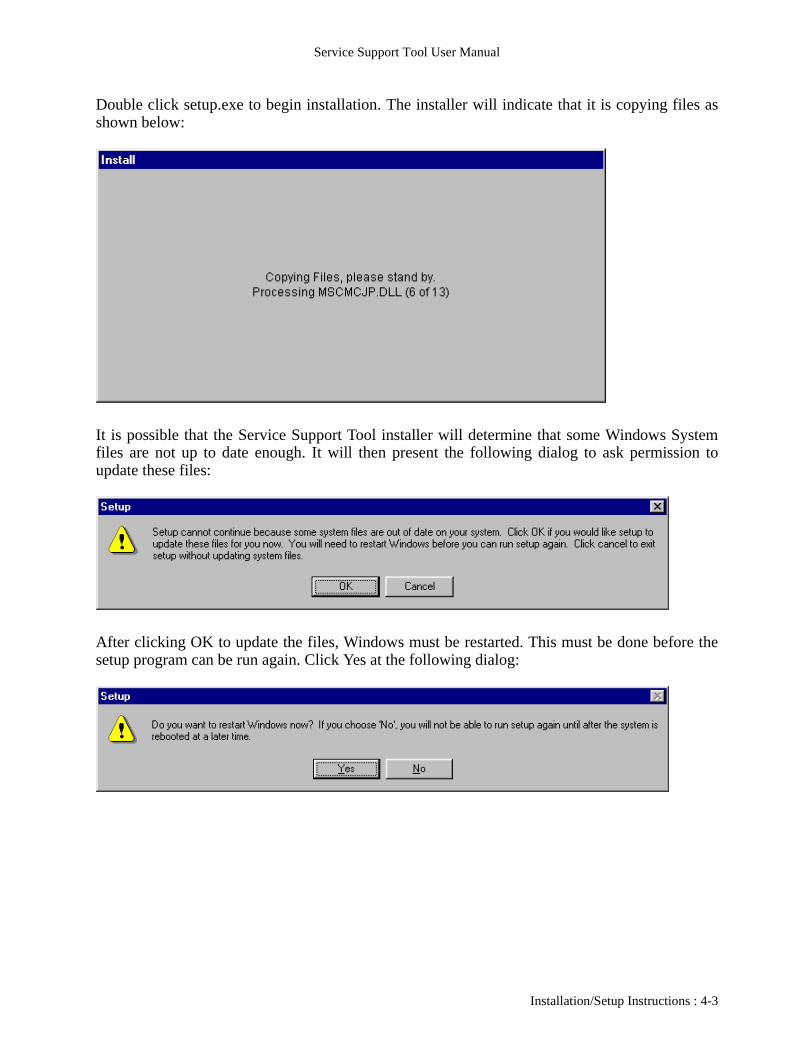
Double click setup.exe to begin installation. The installer will indicate that it is copying files asshown below:
It is possible that the Service Support Tool installer will determine that some Windows Systemfiles are not up to date enough. It will then present the following dialog to ask permission toupdate these files:
After clicking OK to update the files, Windows must be restarted. This must be done before thesetup program can be run again. Click Yes at the following dialog:
Installation/Setup Instructions : 4-3

Service Support Tool User Manual
After Windows restarts, run the setup program again to continue and complete installation. Thedialog shown below will indicate files being copied:
The following Welcome screen will be shown:
4-4 : Installation/Setup Instructions
Service Support Tool User Manual
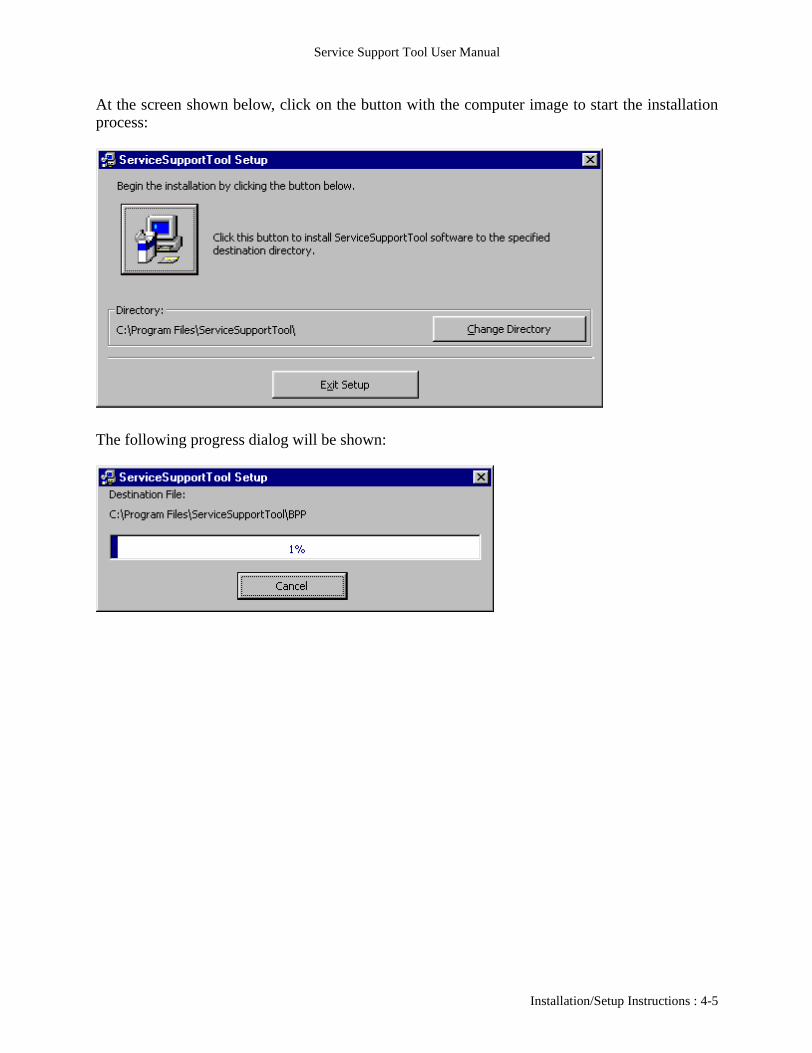
At the screen shown below, click on the button with the computer image to start the installationprocess:
The following progress dialog will be shown:
Installation/Setup Instructions : 4-5
Service Support Tool User Manual
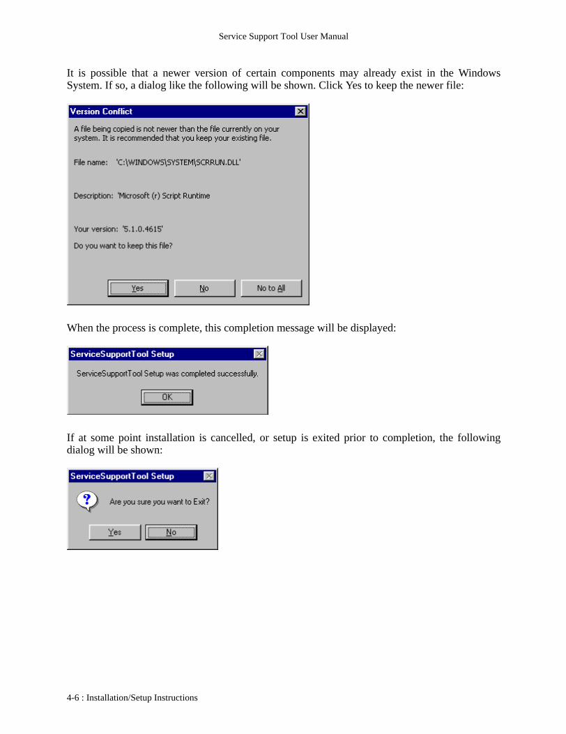
It is possible that a newer version of certain components may already exist in the WindowsSystem. If so, a dialog like the following will be shown. Click Yes to keep the newer file:
When the process is complete, this completion message will be displayed:
If at some point installation is cancelled, or setup is exited prior to completion, the followingdialog will be shown:
4-6 : Installation/Setup Instructions
Service Support Tool User Manual
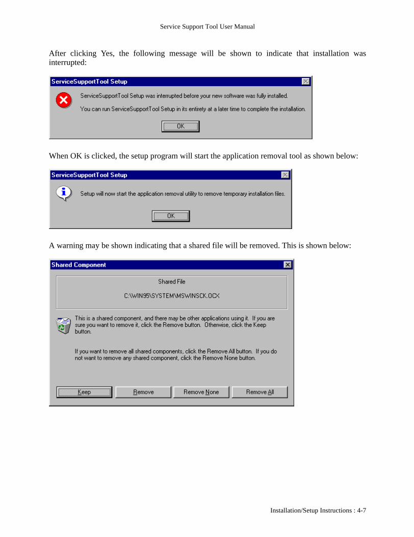
After clicking Yes, the following message will be shown to indicate that installation wasinterrupted:
When OK is clicked, the setup program will start the application removal tool as shown below:
A warning may be shown indicating that a shared file will be removed. This is shown below:
Installation/Setup Instructions : 4-7

Service Support Tool User Manual
Click on Remove All to allow the uninstaller to remove all components. The followingconfirmation screen will be shown:
After clicking OK to continue, a progress bar will be shown. Once all files are removed, thefollowing concluding dialog will be shown:
NOTE : By default, Parallel Mode is set to Low-Speed. This must be changed to High-Speed, ifpossible (This is NOT possible under Windows NT/2000 – even if supported by the hardware).Please refer to the Downloading/Uploading Data section.
4-8 : Installation/Setup Instructions

Service Support Tool User Manual
USB Driver Installation (Windows 98)
As mentioned previously, a third party USB driver (provided with the Service Support Tool) isnecessary to enable flashing over USB from a Windows 98 (1st or 2nd Edition) PC. The specialversion of the installer will place files necessary for this onto the target PC along with the ServiceSupport Tool. The steps detailed here will need to be performed, only once, in addition to thestandard Service Support Tool installation. Again, this is only necessary on Windows 98 PCs.Also, this installation requires the device (i.e. an imageRUNNER 2000) to be connected to the PCthat has the Service Support Tool installed on it.
Connect the PC and the machine via a USB cable. Power on the PC and the machine. Once bothhave started, the “Add New Hardware Wizard” will start and show the following dialog:
Click ‘Next’ and the following dialog will be displayed:
Installation/Setup Instructions : 4-9
Service Support Tool User Manual
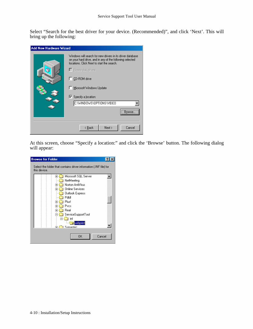
Select “Search for the best driver for your device. (Recommended)”, and click ‘Next’. This willbring up the following:
At this screen, choose “Specify a location:” and click the ‘Browse’ button. The following dialogwill appear:
4-10 : Installation/Setup Instructions
Service Support Tool User Manual
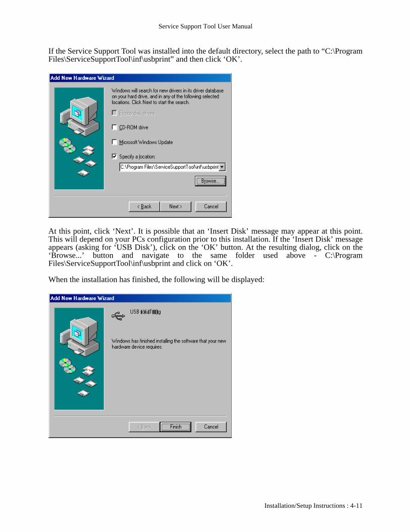
If the Service Support Tool was installed into the default directory, select the path to “C:\ProgramFiles\ServiceSupportTool\inf\usbprint” and then click ‘OK’.
At this point, click ‘Next’. It is possible that an ‘Insert Disk’ message may appear at this point.This will depend on your PCs configuration prior to this installation. If the ‘Insert Disk’ messageappears (asking for ‘USB Disk’), click on the ‘OK’ button. At the resulting dialog, click on the‘Browse...’ button and navigate to the same folder used above - C:\ProgramFiles\ServiceSupportTool\inf\usbprint and click on ‘OK’.
When the installation has finished, the following will be displayed:
Installation/Setup Instructions : 4-11
Service Support Tool User Manual
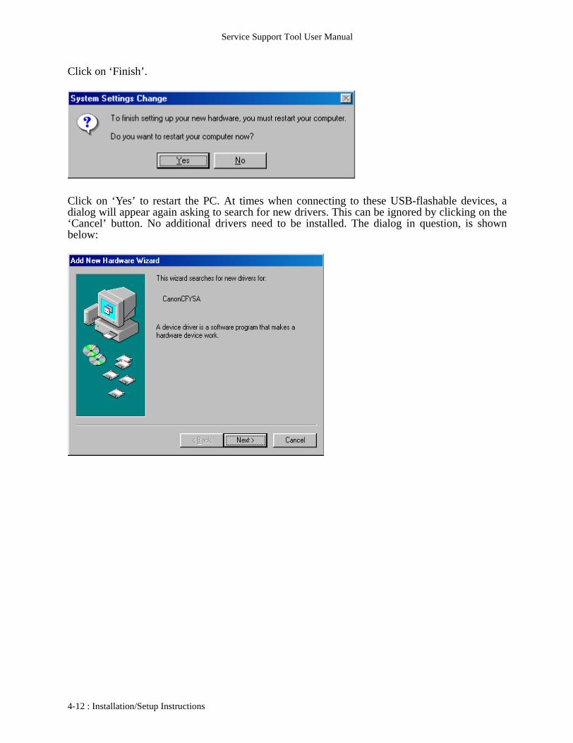
Click on ‘Finish’.
Click on ‘Yes’ to restart the PC. At times when connecting to these USB-flashable devices, adialog will appear again asking to search for new drivers. This can be ignored by clicking on the‘Cancel’ button. No additional drivers need to be installed. The dialog in question, is shownbelow:
4-12 : Installation/Setup Instructions
Service Support Tool User Manual
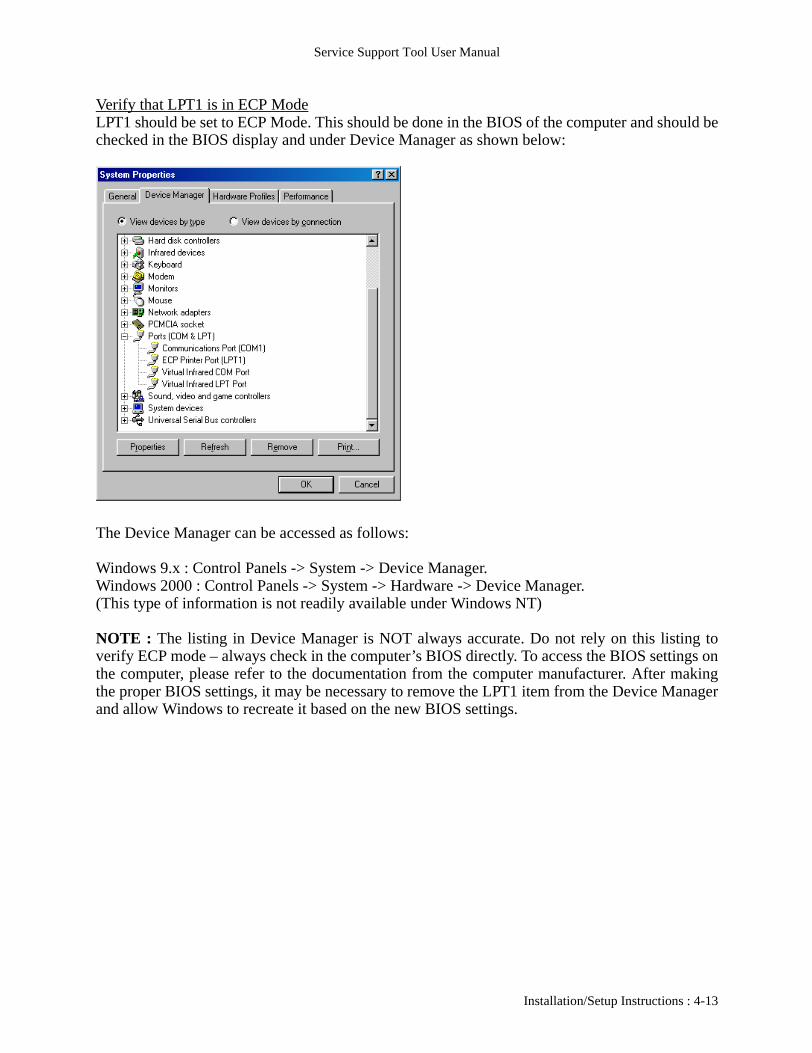
Verify that LPT1 is in ECP ModeLPT1 should be set to ECP Mode. This should be done in the BIOS of the computer and should bechecked in the BIOS display and under Device Manager as shown below:
The Device Manager can be accessed as follows:
Windows 9.x : Control Panels -> System -> Device Manager.Windows 2000 : Control Panels -> System -> Hardware -> Device Manager.(This type of information is not readily available under Windows NT)
NOTE : The listing in Device Manager is NOT always accurate. Do not rely on this listing toverify ECP mode – always check in the computer’s BIOS directly. To access the BIOS settings onthe computer, please refer to the documentation from the computer manufacturer. After makingthe proper BIOS settings, it may be necessary to remove the LPT1 item from the Device Managerand allow Windows to recreate it based on the new BIOS settings.
Installation/Setup Instructions : 4-13

Service Support Tool User Manual
Add New Hardware Message when connecting Computer to DeviceWhen connecting to some of the devices, Windows may detect the device and prompt for addingdrivers as shown below:
Please hit Cancel at this point.
The following ERROR Code will be received if LPT Port is not setup for ECP.
NOTE:
4-14 : Installation/Setup Instructions

Service Support Tool User Manual
5 - Starting the Service Support Tool:
After the Service Support Tool is installed, there will be an entry for it on the Start Menu of theWindows PC. This entry will be under the Programs section as shown below:
If the previous execution of the Service Support Tool ended abnormally (error or other problem),the following message will be displayed:
Click on Yes to continue.
Starting the Service Support Tool : 5-1
Service Support Tool User Manual
Once started, the following startup screen will be displayed:
5-2 : Starting the Service Support Tool

Service Support Tool User Manual
6 - Features and Functions:
The Service Support Tool is divided into two main sections: Controlling Data and Downloading/Uploading Data. Controlling Data is for the Registering or Removal of Data that will be uploadedto a machine as well as removal of data downloaded from a machine. The Downloading/Uploading Data area is where all data transfers to and/or from a machine are setup and controlled.The following sections will describe each function and data type supported by the ServiceSupport Tool.
The Ver. Info. Button will bring up a display of the individual component file versions of the Service Support Tool. The display is as follows:
Features and Functions - General : 6-1

Service Support Tool User Manual
6-2 : Features and Functions - General

Service Support Tool User Manual
6A - Features and Functions: Controlling Data:
The Controlling Data section is entered by clicking on the “To Next” button highlighted in thefollowing figure:
This will bring up the following screen where the indicated functions can be performed:
Each of these functions will be discussed in the sections that follow.
Controlling Data : 6A-1

Service Support Tool User Manual
Additionally, if the Control (Ctrl) key is held down while clicking on “To Next”, the followingdialog will be displayed:
This will allow the ServTool folder (where registered data resides) to be moved to a different localHard Drive or Hard Drive Partition. Network drives are NOT supported.
6A-2 : Controlling Data

Service Support Tool User Manual
Features and Functions: Controlling Data: Registering Firmware/Software
All files need to be registered prior to use – this includes all data types supported by this Tool.When Registering Firmware, the following screen will be displayed:
This will show a list of currently registered data files and provide buttons to register new files –either from the standard “NewROM” folder (created on the HD when the Tool was installed) orfrom a Selected Folder (which allows files on CDs to be registered). When a file is registered, it iscopied onto the HD of the computer and will be available even after the CD is removed.
When “Register from NewROM folder” is clicked, the Service Support Tool will automaticallyregister the firmware file that currently resides in the NewROM folder. There are no extra screensor selections to be made.
Controlling Data : 6A-3

Service Support Tool User Manual
When the Selected Folder method is used, the following screen will be shown:
This defaults to the NewROM folder on the HD but can be changed as shown below (and onfollowing page):
6A-4 : Controlling Data
Service Support Tool User Manual
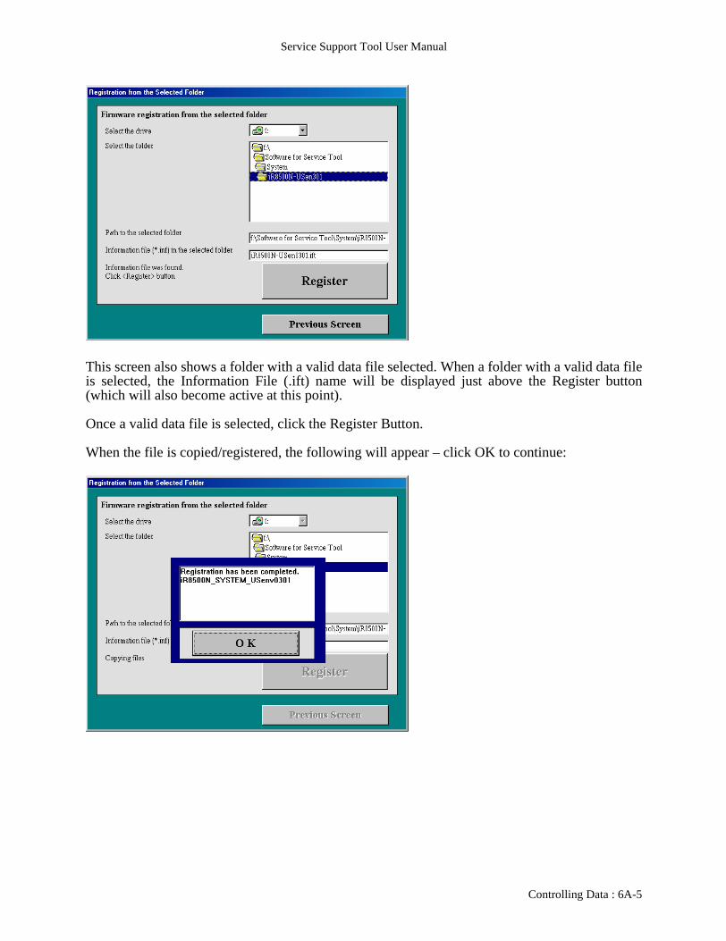
This screen also shows a folder with a valid data file selected. When a folder with a valid data fileis selected, the Information File (.ift) name will be displayed just above the Register button(which will also become active at this point).
Once a valid data file is selected, click the Register Button.
When the file is copied/registered, the following will appear – click OK to continue:
Controlling Data : 6A-5

Service Support Tool User Manual
Features and Functions: Controlling Data: Removing Firmware/Software
To save HD space, outdated firmware files may be removed. Please make sure that there is accessto the data files elsewhere as once they are removed, they are erased from the HD and cannot berecovered. When removing files, the following screen will be displayed:
From here, select the file that is to be removed and click the Remove button to erase it:
6A-6 : Controlling Data

Service Support Tool User Manual
The following screen will be displayed to confirm the removal of the firmware:
When the Remove button is clicked, the firmware will be removed and the following completion screen will be shown:
Click the OK button to continue.
Controlling Data : 6A-7

Service Support Tool User Manual
Features and Functions: Controlling Data: Controlling Backup Data
Some models will allow the backing up of certain data to the HD of a computer from the machine.Any such stored data can be removed from the HD by using this area of the Service Support Tool.When the Controlling Backup Data area is entered, this screen will be seen:
Here a list of stored backup data will be displayed and desired data can be selected and deleted byusing the Remove button.
6A-8 : Controlling Data
Service Support Tool User Manual
6B - Features and Functions: Downloading/Uploading Data:
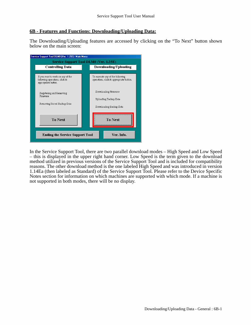
The Downloading/Uploading features are accessed by clicking on the “To Next” button shownbelow on the main screen:
In the Service Support Tool, there are two parallel download modes – High Speed and Low Speed– this is displayed in the upper right hand corner. Low Speed is the term given to the downloadmethod utilized in previous versions of the Service Support Tool and is included for compatibilityreasons. The other download method is the one labeled High Speed and was introduced in version1.14Ea (then labeled as Standard) of the Service Support Tool. Please refer to the Device SpecificNotes section for information on which machines are supported with which mode. If a machine isnot supported in both modes, there will be no display.
Downloading/Uploading Data - General : 6B-1

Service Support Tool User Manual
At various points (if both modes are supported), a screen which contains the “Switch OperationMode” button as shown below may be presented:
When that button is clicked, the following will be displayed:
Here the mode the Service Support Tool communicates with may be changed. Also, notice thatthe current method is displayed in the upper right hand corner of this and almost all otherwindows.
6B-2 : Downloading/Uploading Data - General

Service Support Tool User Manual
When installing the Service Support Tool, the default is set to Low-Speed. This will need to bechanged to High-Speed, if possible. In some cases, the combination of computer and OperatingSystem may make High-Speed impossible. In certain cases, the Service Support Tool will be ableto detect this and will not allow High-Speed to be chosen. This is also the case with Windows NTand 2000 – High-Speed will NOT be a selectable option (this is an OS limitation). In these cases,the mode cannot be changed and the screen will appear as follows:
Some firmware files/machines will allow for Network Downloading (via TCP/IP) in addition toparallel downloading. Network downloading capability will be listed in the Device Specific Notessection as well as under the file types that may support it. The connection for Networkdownloading should be made with a Cross-Over Ethernet cable. This is a special Ethernet cablemade to connect two devices only. When utilizing Network downloading, the computer and thedevice must employ TCP/IP addresses that are of the same segment. The easiest way toaccomplish this is by changing the device TCP/IP address to be the same as the computer TCP/IPaddress – except for the last number. For example – if the computer is 146.184.129.127, make thedevice 146.184.129.128. Utilize the same Subnet Mask and Gateway as listed on the computer.NOTE : Before making any changes to the network configuration of an installed machine, printout a configuration page so that there is a record of the original settings. After flashing, return themachine to those original settings.
The information for the computer can be found under the TCP/IP Properties, listed in ControlPanels -> Network (Windows 9.x), Control Panels -> Network -> Protocols (Windows NT) orControl Panels -> Network and Dial-up Connections -> appropriate connection document(Windows 2000).
NOTE : Network Downloading is only available if the machine has entered Download Modethrough Service Mode. This is the only time that the network protocols will be active fordownloading.
Downloading/Uploading Data - General : 6B-3

Service Support Tool User Manual
When utilizing Network Downloading, the TCP/IP address of the target device will be displayedin the upper right hand corner as shown below:
During the download procedure (which is detailed in the following sections), a display as followswill be presented:
At the bottom of this display, is a counter showing Time Remaining for processing of the data filejust transferred to the machine. In both High Speed and Low Speed modes, this counter shouldfunction. It has been observed that the initial starting value may not be accurate. Therefore thecountdown may proceed into negative numbers, but more probable is the countdown stoppingprior to reaching zero.
6B-4 : Downloading/Uploading Data - General

Service Support Tool User Manual
Some firmware files/machines will allow (or require) downloading via USB. As with the paralleldownloading, it is possible for there to be more than one USB connoctor on a machine. Careshould be taken to utilize the proper USB connector.
The following sections will discuss each data type individually. Each section assumes that anIEEE1284 Parallel Cable is attached from the PC to the appropriate parallel port on the machineto be worked on. Please refer to the specific model’s Service Manual for details on preparing themachine for downloading. For file types that support Network Downloading, the steps that aredifferent from parallel Downloading will also be shown and will be preceded by a Network label.This will also be done for those steps that are related to USB Downloading and will be noted by aUSB label.
Downloading/Uploading Data - General : 6B-5

Service Support Tool User Manual
6B-6 : Downloading/Uploading Data - General

Service Support Tool User Manual
6B1 - Features and Functions: Downloading/Uploading Data:FDIMM:
From the Selecting Model/Unit screen, select the appropriate FDIMM file as shown below:
Instructions will appear as follows:
Downloading/Uploading Data - FDIMM : 6B1-1

Service Support Tool User Manual
The Service Support Tool will connect to the machine:
If necessary, the Tool will wait for the machine:
6B1-2 : Downloading/Uploading Data - FDIMM
Service Support Tool User Manual
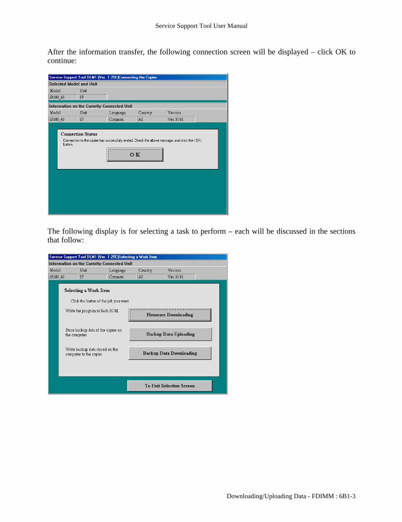
After the information transfer, the following connection screen will be displayed – click OK tocontinue:
The following display is for selecting a task to perform – each will be discussed in the sectionsthat follow:
Downloading/Uploading Data - FDIMM : 6B1-3

Service Support Tool User Manual
After completing a given task, the Tool will return to the screen shown on the previous page.When “To Unit Selection Screen” is clicked, the following “Cleanup” screen will be displayed:
Click OK to continue.
6B1-4 : Downloading/Uploading Data - FDIMM

Service Support Tool User Manual
Features and Functions: Downloading/Uploading Data:FDIMM: Firmware Downloading:
Selecting Firmware Downloading will bring up the following display.
Select desired version and click Start to continue:
Downloading/Uploading Data - FDIMM : 6B1-5
Service Support Tool User Manual
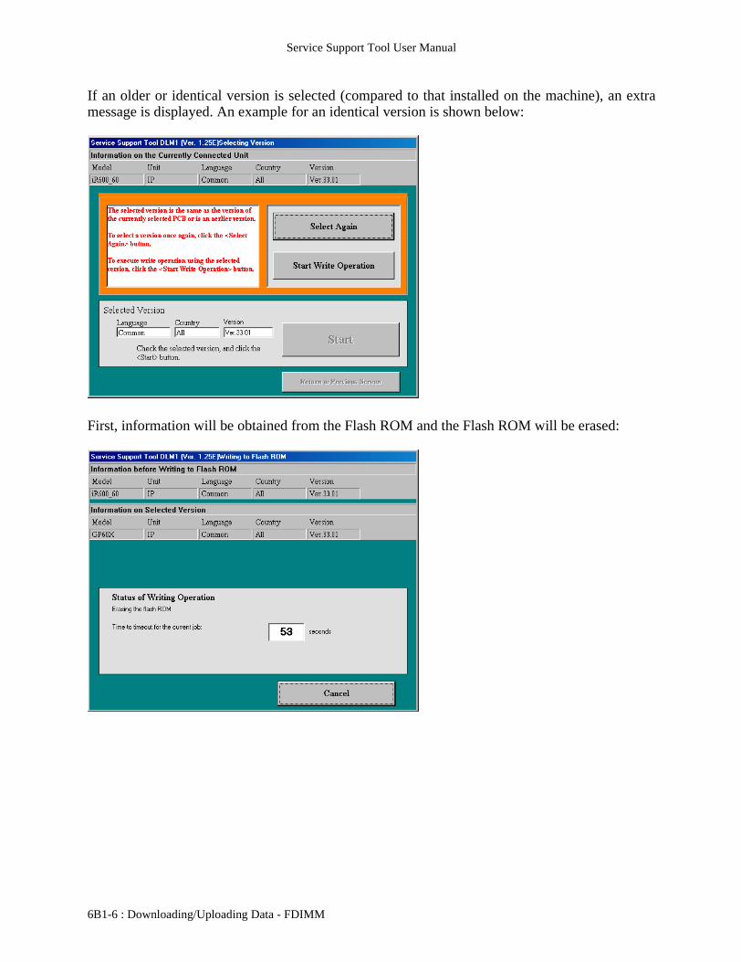
If an older or identical version is selected (compared to that installed on the machine), an extramessage is displayed. An example for an identical version is shown below:
First, information will be obtained from the Flash ROM and the Flash ROM will be erased:
6B1-6 : Downloading/Uploading Data - FDIMM

Service Support Tool User Manual
Data is then transferred/written to the Flash ROM:
After writing is complete, checksums are compared:
Downloading/Uploading Data - FDIMM : 6B1-7

Service Support Tool User Manual
The results of the Flash checksum are displayed – click OK to continue:
6B1-8 : Downloading/Uploading Data - FDIMM

Service Support Tool User Manual
Features and Functions: Downloading/Uploading Data:FDIMM: Backup Data Uploading:
Certain models will allow the saving of certain data to a computer by utilizing this section of theService Support Tool. When performing this function, the following will be displayed to allow theselection of the desired data:
After selecting the data, Start can be clicked to continue:
Downloading/Uploading Data - FDIMM : 6B1-9
Service Support Tool User Manual
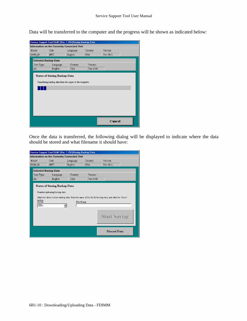
Data will be transferred to the computer and the progress will be shown as indicated below:
Once the data is transferred, the following dialog will be displayed to indicate where the datashould be stored and what filename it should have:
6B1-10 : Downloading/Uploading Data - FDIMM
Service Support Tool User Manual
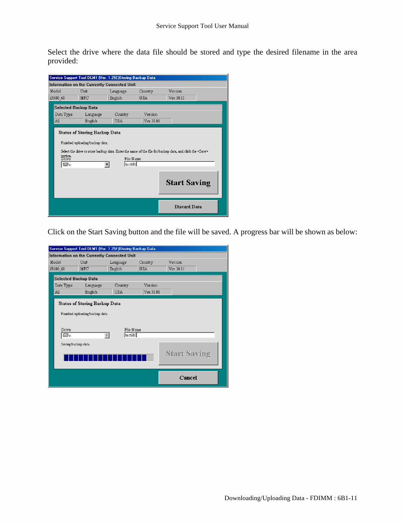
Select the drive where the data file should be stored and type the desired filename in the areaprovided:
Click on the Start Saving button and the file will be saved. A progress bar will be shown as below:
Downloading/Uploading Data - FDIMM : 6B1-11
Service Support Tool User Manual
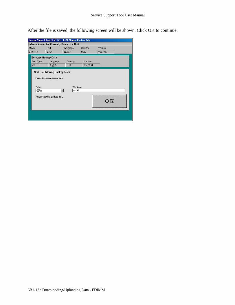
After the file is saved, the following screen will be shown. Click OK to continue:
6B1-12 : Downloading/Uploading Data - FDIMM

Service Support Tool User Manual
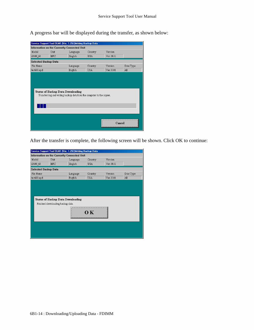
Features and Functions:Downloading/Uploading Data:FDIMM:BackupData Downloading:
To return previously saved data to a machine, the following dialog would be used to indicatewhich file is to be transferred:
Select the proper file from the drop down menu and click Start to send the data to the machine.
Downloading/Uploading Data - FDIMM : 6B1-13
Service Support Tool User Manual
A progress bar will be displayed during the transfer, as shown below:
After the transfer is complete, the following screen will be shown. Click OK to continue:
6B1-14 : Downloading/Uploading Data - FDIMM
Service Support Tool User Manual
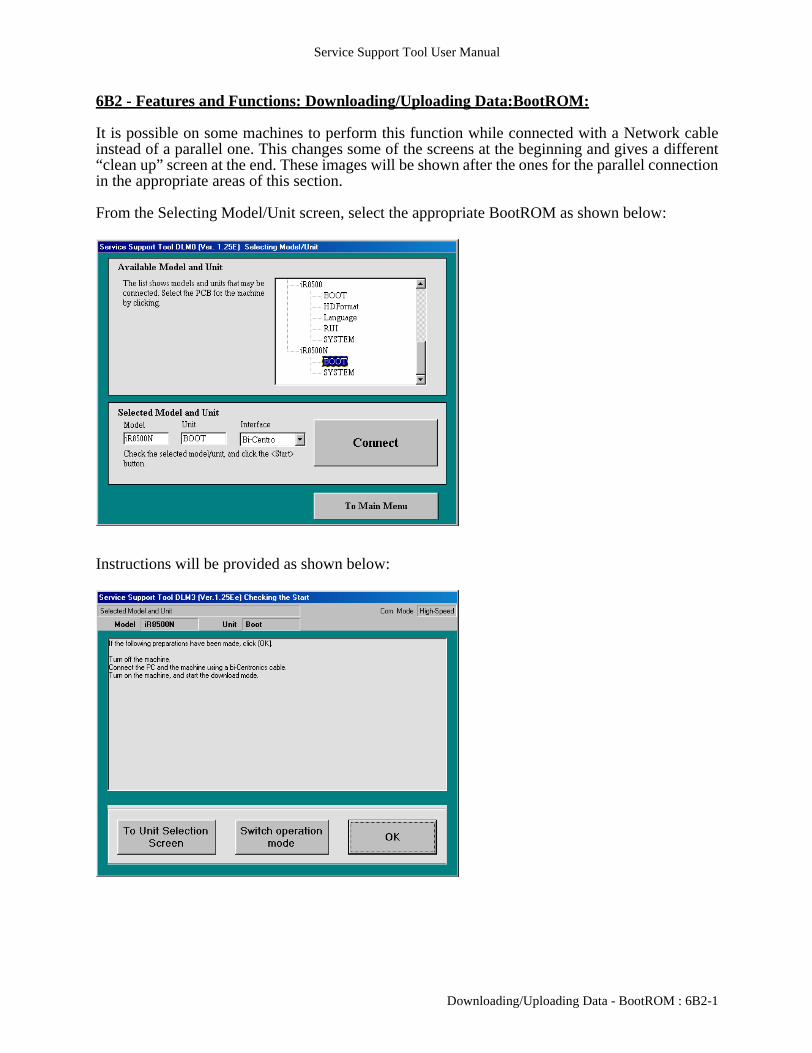
6B2 - Features and Functions: Downloading/Uploading Data:BootROM:
It is possible on some machines to perform this function while connected with a Network cableinstead of a parallel one. This changes some of the screens at the beginning and gives a different“clean up” screen at the end. These images will be shown after the ones for the parallel connectionin the appropriate areas of this section.
From the Selecting Model/Unit screen, select the appropriate BootROM as shown below:
Instructions will be provided as shown below:
Downloading/Uploading Data - BootROM : 6B2-1
Service Support Tool User Manual
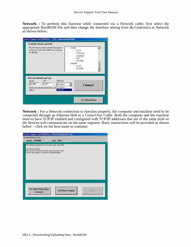
Network : To perform this function while connected via a Network cable, first select theappropriate BootROM file and then change the Interface setting from Bi-Centronics to Networkas shown below:
Network : For a Network connection to function properly, the computer and machine need to beconnected through an Ethernet Hub or a Cross-Over Cable. Both the computer and the machineneed to have TCP/IP enabled and configured with TCP/IP addresses that are of the same style sothe devices will communicate on the same segment. Basic instructions will be provided as shownbelow – click on Set host name to continue:
6B2-2 : Downloading/Uploading Data - BootROM

Service Support Tool User Manual
Network : A dialog will come up, as shown here:
Network : Enter the TCP/IP address of the machine that is to be communicated with as indicatedbelow – click OK to continue:
Downloading/Uploading Data - BootROM : 6B2-3

Service Support Tool User Manual
Network : This will return to the screen shown below. Click OK to continue:
The Service Support Tool will obtain some information from the machine, as shown below:
6B2-4 : Downloading/Uploading Data - BootROM

Service Support Tool User Manual
After the information is obtained, the following connection screen will be displayed – click OK tocontinue:
The following display is for selecting a task to perform – click BootROM Download to continue:
Downloading/Uploading Data - BootROM : 6B2-5

Service Support Tool User Manual
The screen below will display the available versions:
Select the desired version from the list and click the Start button:
6B2-6 : Downloading/Uploading Data - BootROM

Service Support Tool User Manual
If the file being sent is older or the same version, an extra dialog will appear. The following is anexample of the same version as installed being resent:
Data will then be transferred and progress is displayed as follows:
Downloading/Uploading Data - BootROM : 6B2-7

Service Support Tool User Manual
Once data transfer is complete, additional processing is performed on the machine and thefollowing will be displayed as this is done (please see note at beginning of Downloading/Uploading section with regard to this screen and the time displayed):
Once the additional processing is done, checksums will be compared and the following will bedisplayed – click OK to continue:
6B2-8 : Downloading/Uploading Data - BootROM

Service Support Tool User Manual
When exiting out from this section of the Tool, a “Cleanup” screen will be displayed as follows:
Network : The “Cleanup” screen for a Network setup is as follows:
Downloading/Uploading Data - BootROM : 6B2-9

Service Support Tool User Manual
6B2-10 : Downloading/Uploading Data - BootROM

Service Support Tool User Manual
6B3 - Features and Functions: Downloading/Uploading Data:HD Format:
It is possible on some machines to perform this function while connected with a Network cableinstead of a parallel one. This changes some of the screens at the beginning and gives a different“clean up” screen at the end. These images will be shown after the ones for the parallel connectionin the appropriate areas of this section.
Some machines will have Hard Drives (Service Parts) provided blank. In this case, there will bean HDFormat data file that can be used with this Tool to prepare the HD for the System Softwareinstallation.
As mentioned in the Device Specific Notes section, there are different methods for gettingmachines into a download mode to accept data. For the devices supporting the HDFormat files,there are two methods. In the Device Specific Notes section, these are referred to as DownloadModes B (accessed within Service Mode on the device) and C (holding down 2 & 8 whilepowering on the device). Each mode allows a different level of access to the HD using HDFormat.Mode B allows limited access and can only format certain partitions – it does not allow for acomplete format of the drive. Mode C allows for a complete format, but can only be done whenconnected via a parallel cable – the network interface is NOT enabled in Mode C, only in ModeB. Screenshots to account for both modes will be shown.
In this case, the proper HDFormat file needs to be selected as shown below:
NOTE: Only to be performed if aNEW BLANK HD is installed.
Downloading/Uploading Data - HD Format : 6B3-1
Service Support Tool User Manual
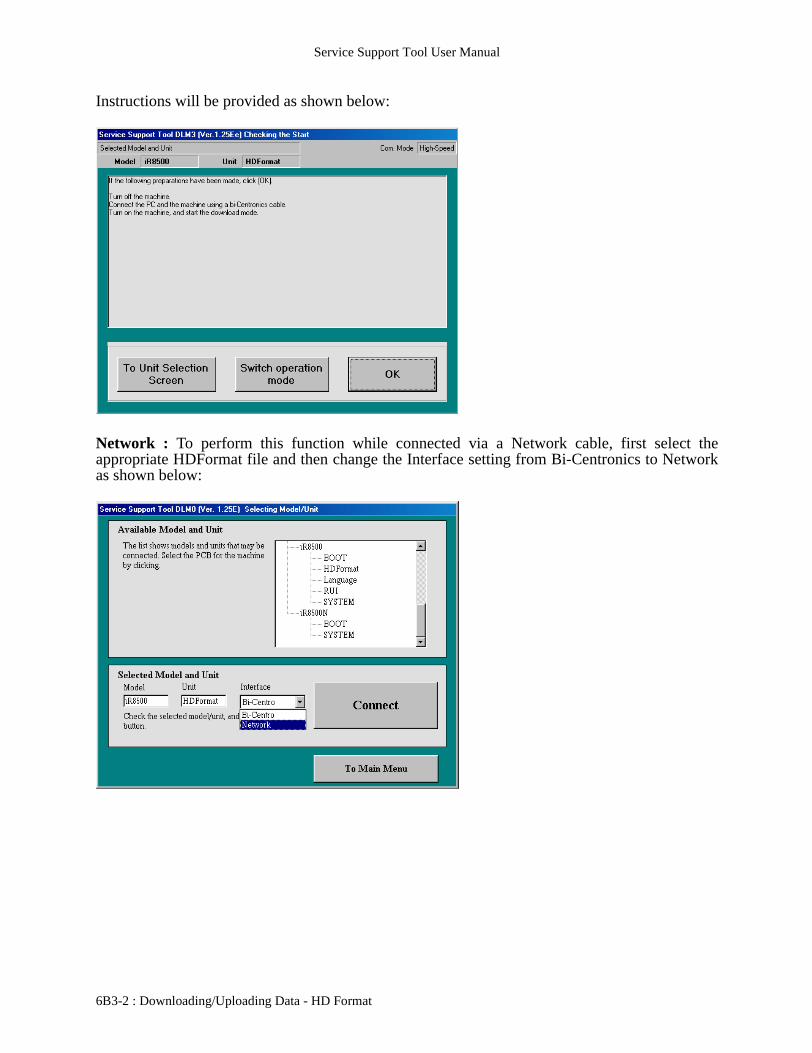
Instructions will be provided as shown below:
Network : To perform this function while connected via a Network cable, first select theappropriate HDFormat file and then change the Interface setting from Bi-Centronics to Networkas shown below:
6B3-2 : Downloading/Uploading Data - HD Format
Service Support Tool User Manual
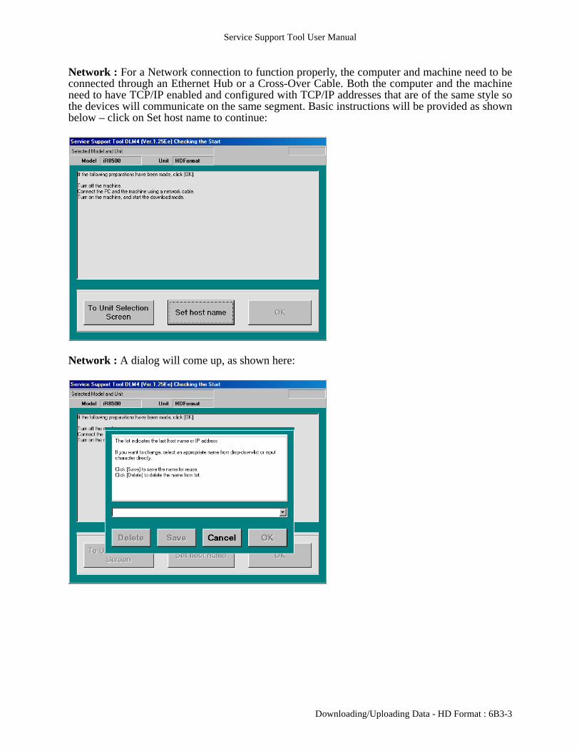
Network : For a Network connection to function properly, the computer and machine need to beconnected through an Ethernet Hub or a Cross-Over Cable. Both the computer and the machineneed to have TCP/IP enabled and configured with TCP/IP addresses that are of the same style sothe devices will communicate on the same segment. Basic instructions will be provided as shownbelow – click on Set host name to continue:
Network : A dialog will come up, as shown here:
Downloading/Uploading Data - HD Format : 6B3-3
Service Support Tool User Manual
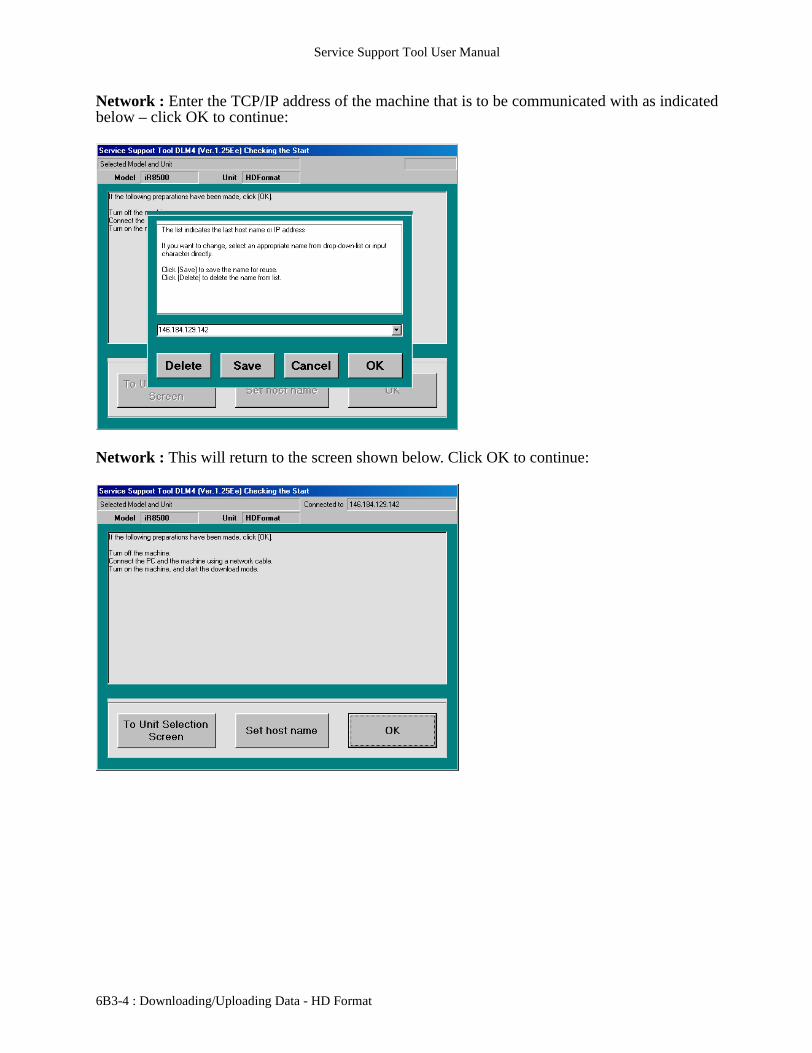
Network : Enter the TCP/IP address of the machine that is to be communicated with as indicatedbelow – click OK to continue:
Network : This will return to the screen shown below. Click OK to continue:
6B3-4 : Downloading/Uploading Data - HD Format

Service Support Tool User Manual
The Service Support Tool will obtain some information from the machine, as shown below:
The following three sections will show the details for the different HD Format modes:Mode B - Partition formatting only (immediately following)Mode C - Partition format (pg. 6B3-9)Mode C - Full HD format (pg. 6B3-12)
Mode BFormatting a desired partition is detailed as follows:
After the information is obtained, the following connection screen will be displayed – click OK tocontinue:
Downloading/Uploading Data - HD Format : 6B3-5

Service Support Tool User Manual
The following display is for selecting a task to perform – click Format to continue:
The screen below will display the available partitions – select the desired partition:
6B3-6 : Downloading/Uploading Data - HD Format

Service Support Tool User Manual
Once the desired partition is selected, click Start to continue:
The following Final Confirmation screen will be presented – click Start to begin the actual HDFormatting:
Downloading/Uploading Data - HD Format : 6B3-7

Service Support Tool User Manual
The screen for the start of the format process may only be shown briefly as formatting is quick but it will be displayed as follows:
The following screen will appear once formatting is completed – click OK to continue:
6B3-8 : Downloading/Uploading Data - HD Format
Service Support Tool User Manual
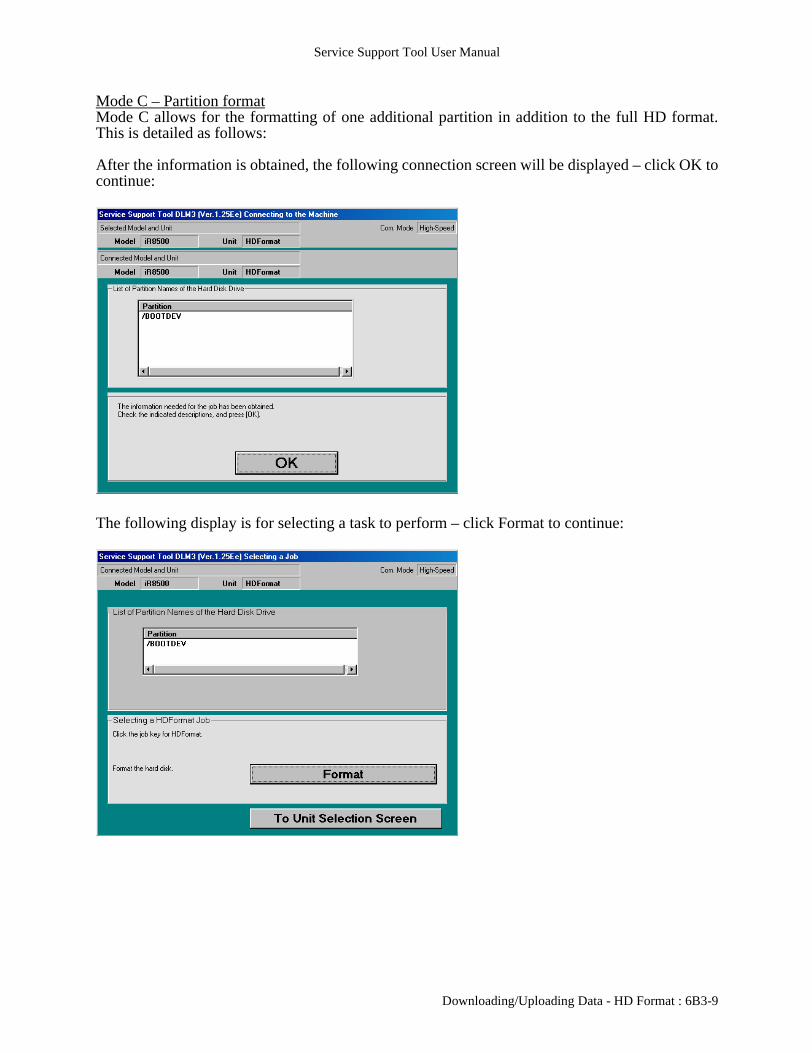
Mode C – Partition formatMode C allows for the formatting of one additional partition in addition to the full HD format.This is detailed as follows:
After the information is obtained, the following connection screen will be displayed – click OK tocontinue:
The following display is for selecting a task to perform – click Format to continue:
Downloading/Uploading Data - HD Format : 6B3-9

Service Support Tool User Manual
The screen below will display the available partition – select the available partition:
Once the partition is selected, click Start to continue:
6B3-10 : Downloading/Uploading Data - HD Format
Service Support Tool User Manual
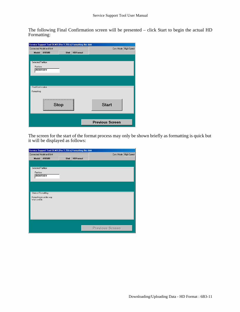
The following Final Confirmation screen will be presented – click Start to begin the actual HDFormatting:
The screen for the start of the format process may only be shown briefly as formatting is quick but it will be displayed as follows:
Downloading/Uploading Data - HD Format : 6B3-11

Service Support Tool User Manual
The following screen will appear once formatting is completed – click OK to continue:
Mode C – Full HD formatA complete format of the HD is detailed as follows:
After the information is obtained, the following connection screen will be displayed – click OK tocontinue:
6B3-12 : Downloading/Uploading Data - HD Format

Service Support Tool User Manual
The following display is for selecting a task to perform – click Format to continue:
The screen below will display the available partition – select Start (under All Partitions) toperform a complete format:
Downloading/Uploading Data - HD Format : 6B3-13

Service Support Tool User Manual
The following Final Confirmation screen will be presented – click Start to begin the actual HDFormatting:
The screen for the start of the format process may only be shown briefly as formatting is quick but it will be displayed as follows:
6B3-14 : Downloading/Uploading Data - HD Format

Service Support Tool User Manual
The following screen will appear once formatting is completed – click OK to continue:
All Modes
When exiting out from this section of the Tool, a “Cleanup” screen will be displayed as follows:
Downloading/Uploading Data - HD Format : 6B3-15

Service Support Tool User Manual
Network : The “Cleanup” screen for a Network setup is as follows:
NOTE : When performing a full HD format, there will be no System Software left for themachine to use. This will cause an error code to be displayed on startup – E602-0002. Rememberto install System Software (and other files as necessary, such as RUI and Language) to return themachine to a functional state. Some devices have more than one version of System Software(Copier vs. Network) – select the appropriate one and follow the instructions outlined in theSystem Software:Updating System Software section.
6B3-16 : Downloading/Uploading Data - HD Format
Service Support Tool User Manual
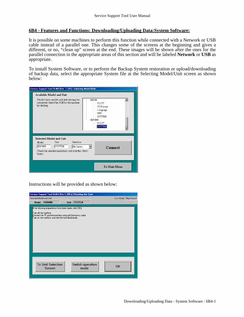
6B4 - Features and Functions: Downloading/Uploading Data:System Software:
It is possible on some machines to perform this function while connected with a Network or USBcable instead of a parallel one. This changes some of the screens at the beginning and gives adifferent, or no, “clean up” screen at the end. These images will be shown after the ones for theparallel connection in the appropriate areas of this section and will be labeled Network or USB asappropriate.
To install System Software, or to perform the Backup System restoration or upload/downloadingof backup data, select the appropriate System file at the Selecting Model/Unit screen as shownbelow:
Instructions will be provided as shown below:
Downloading/Uploading Data - System Software : 6B4-1

Service Support Tool User Manual
USB: To perform this function via a USB cable, first select the appropriate System file and verifythat USB is the Interface setting:
USB: Instructions will be provided as shown below:
6B4-2 : Downloading/Uploading Data - System Software
Service Support Tool User Manual
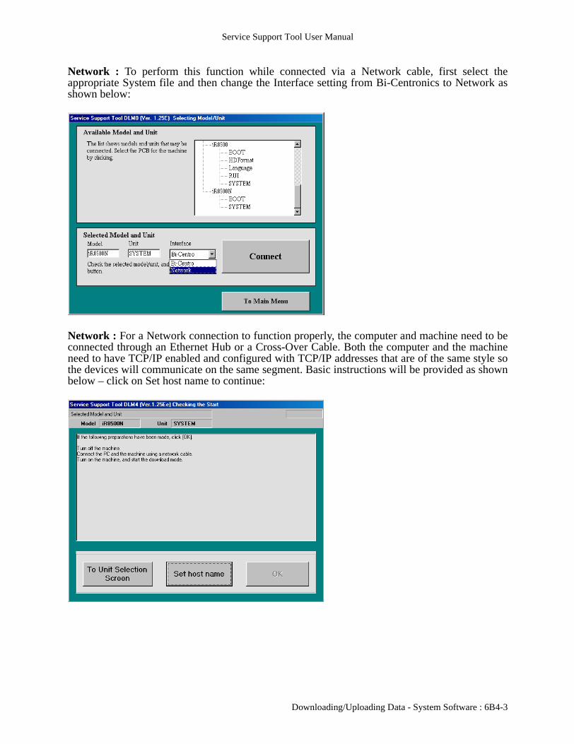
Network : To perform this function while connected via a Network cable, first select theappropriate System file and then change the Interface setting from Bi-Centronics to Network asshown below:
Network : For a Network connection to function properly, the computer and machine need to beconnected through an Ethernet Hub or a Cross-Over Cable. Both the computer and the machineneed to have TCP/IP enabled and configured with TCP/IP addresses that are of the same style sothe devices will communicate on the same segment. Basic instructions will be provided as shownbelow – click on Set host name to continue:
Downloading/Uploading Data - System Software : 6B4-3
Service Support Tool User Manual
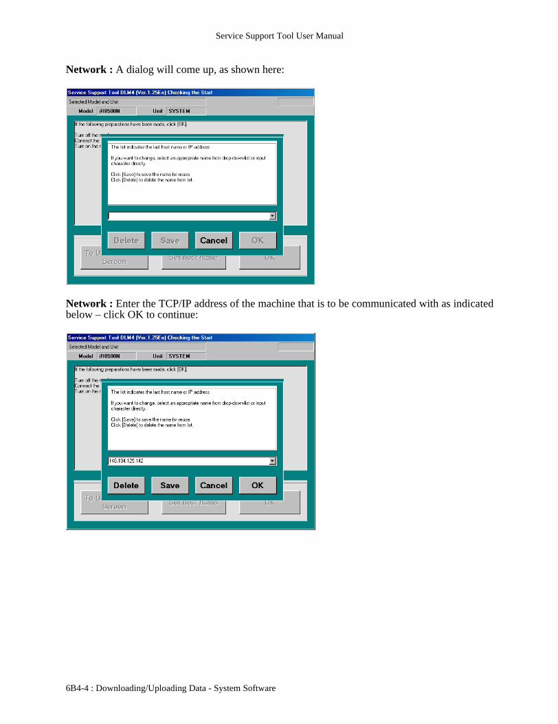
Network : A dialog will come up, as shown here:
Network : Enter the TCP/IP address of the machine that is to be communicated with as indicatedbelow – click OK to continue:
6B4-4 : Downloading/Uploading Data - System Software
Service Support Tool User Manual
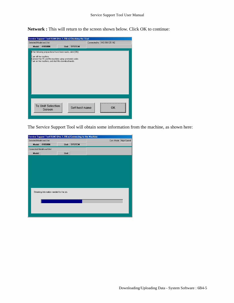
Network : This will return to the screen shown below. Click OK to continue:
The Service Support Tool will obtain some information from the machine, as shown here:
Downloading/Uploading Data - System Software : 6B4-5

Service Support Tool User Manual
The following connection screen will then be displayed – click OK to continue:
The following display is for selecting a task to perform – each will be discussed in the sectionsthat follow:
6B4-6 : Downloading/Uploading Data - System Software

Service Support Tool User Manual
Features and Functions: Downloading/Uploading Data:System Software:Updating System Software:
Selecting System Software Download will bring up the following display:
Select the version of System Software desired and click Start to continue:
Downloading/Uploading Data - System Software : 6B4-7

Service Support Tool User Manual
If an older or identical version of software is selected (compared to that installed on the machine),an extra message is displayed. An example for identical software is shown below:
Data transfer will commence after hitting Start and will be shown as follows:
6B4-8 : Downloading/Uploading Data - System Software
Service Support Tool User Manual
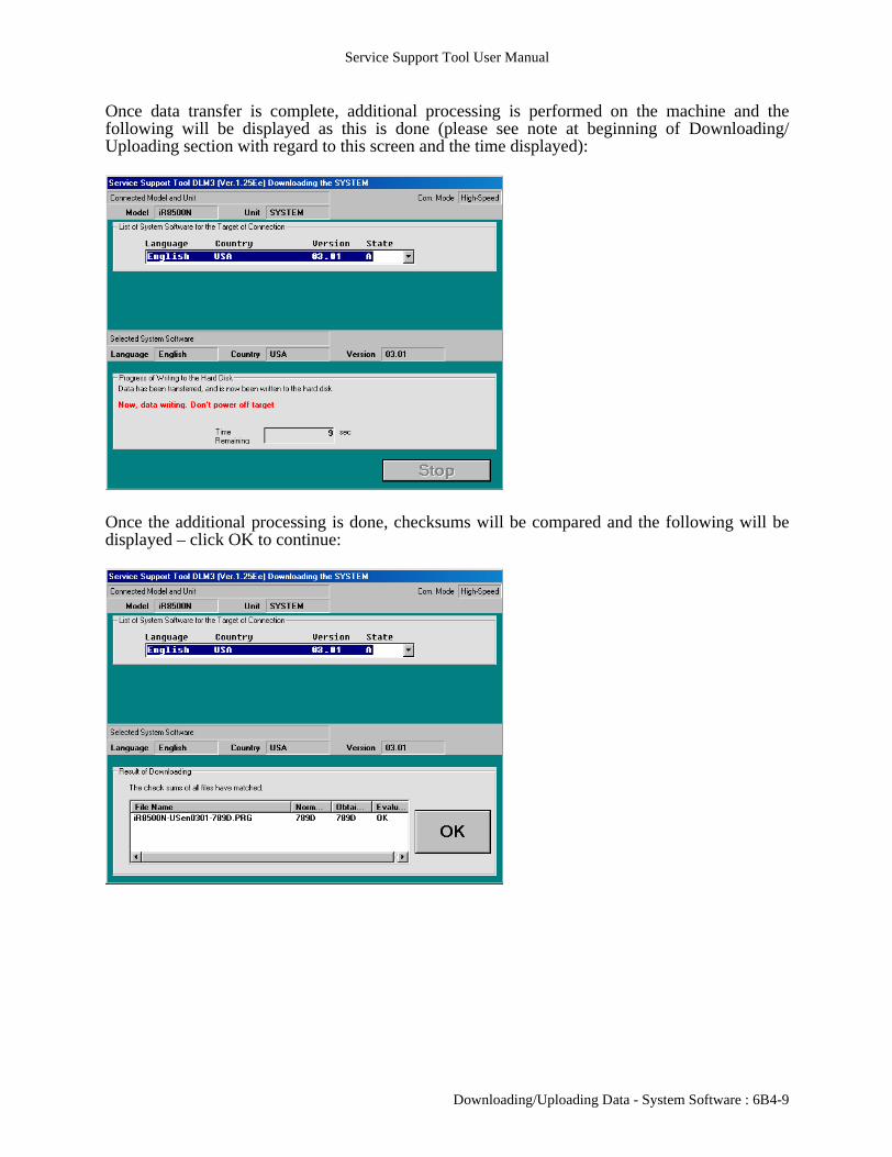
Once data transfer is complete, additional processing is performed on the machine and thefollowing will be displayed as this is done (please see note at beginning of Downloading/Uploading section with regard to this screen and the time displayed):
Once the additional processing is done, checksums will be compared and the following will bedisplayed – click OK to continue:
Downloading/Uploading Data - System Software : 6B4-9
Service Support Tool User Manual
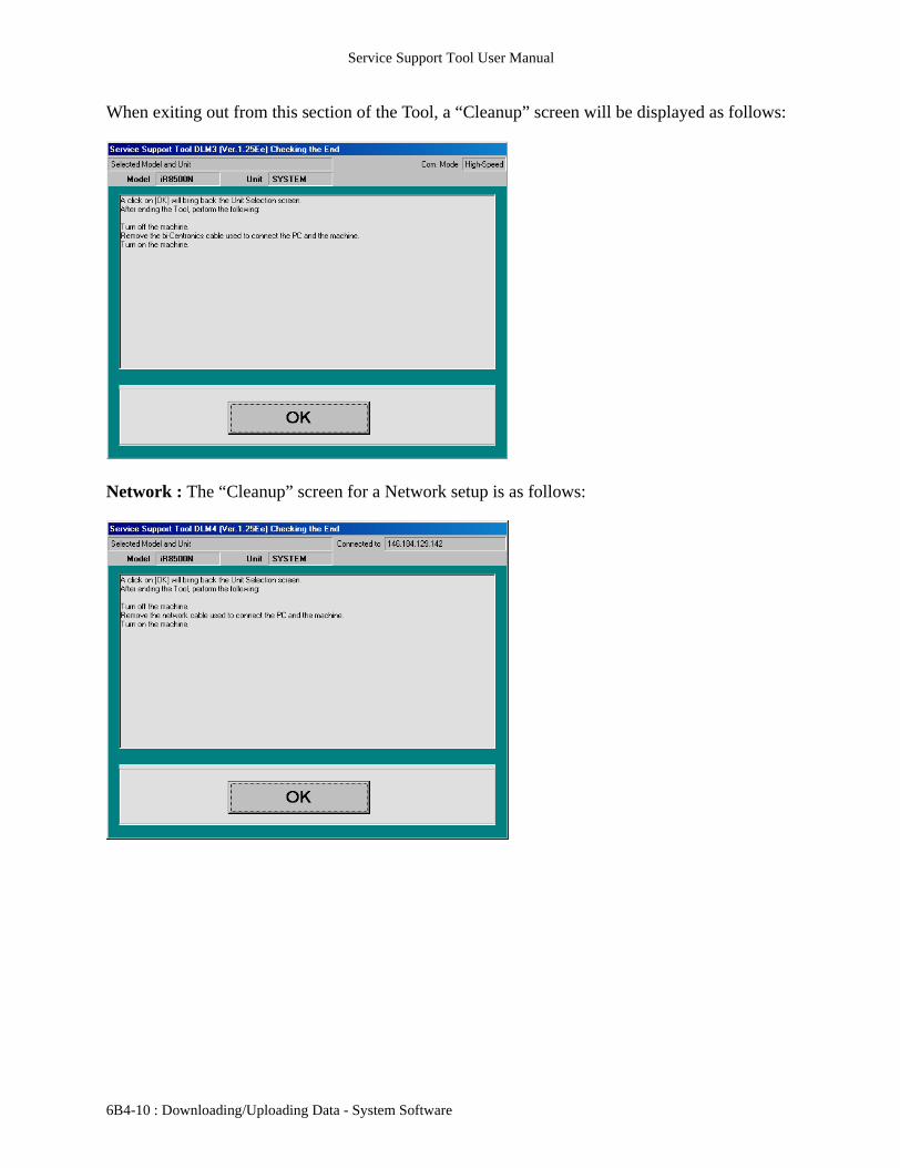
When exiting out from this section of the Tool, a “Cleanup” screen will be displayed as follows:
Network : The “Cleanup” screen for a Network setup is as follows:
6B4-10 : Downloading/Uploading Data - System Software
Service Support Tool User Manual
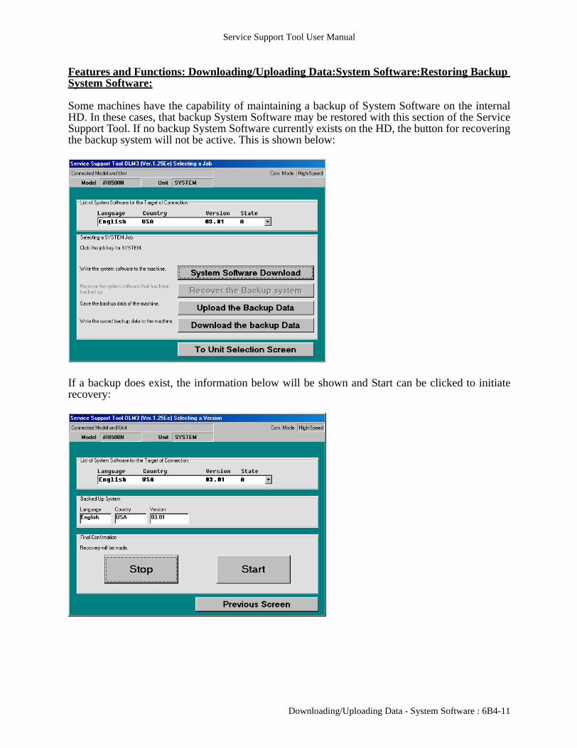
Features and Functions: Downloading/Uploading Data:System Software:Restoring Backup System Software:
Some machines have the capability of maintaining a backup of System Software on the internalHD. In these cases, that backup System Software may be restored with this section of the ServiceSupport Tool. If no backup System Software currently exists on the HD, the button for recoveringthe backup system will not be active. This is shown below:
If a backup does exist, the information below will be shown and Start can be clicked to initiaterecovery:
Downloading/Uploading Data - System Software : 6B4-11

Service Support Tool User Manual
The start of the recovery process will be indicated as shown below:
Once recovery is completed, the screen will change to the following:
6B4-12 : Downloading/Uploading Data - System Software

Service Support Tool User Manual
Features and Functions: Downloading/Uploading Data:System Software:Uploading Backup Data:
Certain models will allow the saving of certain data to a computer by utilizing this section of theService Support Tool. When performing this function, the following will be displayed to allow theselection of the desired data:
After selecting the data, Start Storing can be clicked to continue:
Downloading/Uploading Data - System Software : 6B4-13

Service Support Tool User Manual
Data will be transferred to the computer and the progress will be shown as indicated below:
Once the data is transferred, the following dialog will be displayed to indicate where the datashould be stored:
6B4-14 : Downloading/Uploading Data - System Software

Service Support Tool User Manual
Enter the desired filename in the area provided and click on Save:
Once the save is completed, the following will be displayed:
Downloading/Uploading Data - System Software : 6B4-15
Service Support Tool User Manual
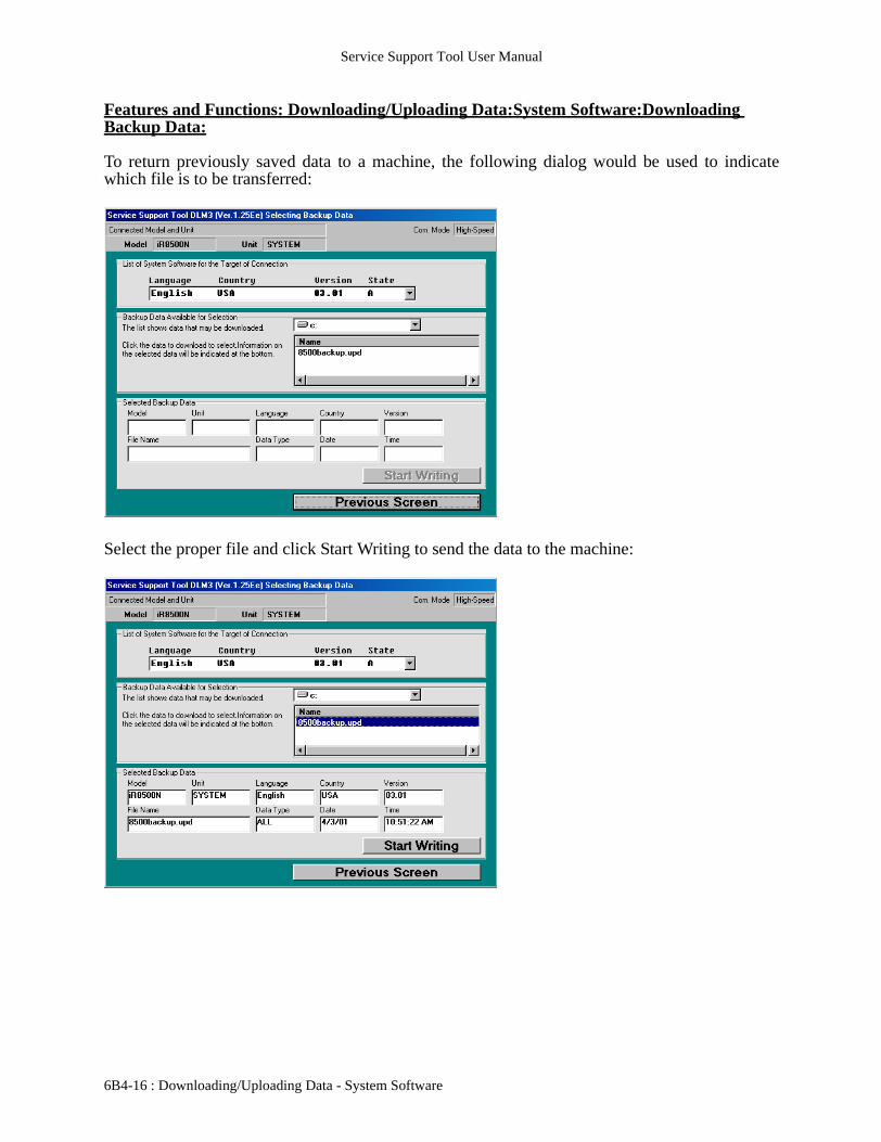
Features and Functions: Downloading/Uploading Data:System Software:Downloading Backup Data:
To return previously saved data to a machine, the following dialog would be used to indicatewhich file is to be transferred:
Select the proper file and click Start Writing to send the data to the machine:
6B4-16 : Downloading/Uploading Data - System Software

Service Support Tool User Manual
Progress will be indicated as shown below:
The following will be displayed when the process is complete:
Downloading/Uploading Data - System Software : 6B4-17

Service Support Tool User Manual
6B4-18 : Downloading/Uploading Data - System Software

Service Support Tool User Manual
6B5 - Features and Functions: Downloading/Uploading Data:RUI:
It is possible on some machines to perform this function while connected with a Network cableinstead of a parallel one. This changes some of the screens at the beginning and gives a different“clean up” screen at the end. These images will be shown after the ones for the parallel connectionin the appropriate areas of this section.
To install the RUI (Remote User Interface), select the appropriate RUI file at the Selecting Model/Unit screen as shown below:
Instructions will be provided as shown below:
Downloading/Uploading Data - RUI : 6B5-1

Service Support Tool User Manual
Network : To perform this function while connected via a Network cable, first select theappropriate RUI file and then change the Interface setting from Bi-Centronics to Network asshown below:
Network : For a Network connection to function properly, the computer and machine need to beconnected through an Ethernet Hub or a Cross-Over Cable. Both the computer and the machineneed to have TCP/IP enabled and configured with TCP/IP addresses that are of the same style sothe devices will communicate on the same segment. Basic instructions will be provided as shownbelow – click on Set host name to continue:
6B5-2 : Downloading/Uploading Data - RUI

Service Support Tool User Manual
Network : A dialog will come up, as shown here:
Network : Enter the TCP/IP address of the machine that is to be communicated with as indicatedbelow – click OK to continue:
Downloading/Uploading Data - RUI : 6B5-3

Service Support Tool User Manual
Network : This will return to the screen shown below. Click OK to continue:
The Service Support Tool will obtain some information from the machine, as shown below:
6B5-4 : Downloading/Uploading Data - RUI

Service Support Tool User Manual
Afterwards, the following connection screen will be displayed – click OK to continue:
The following display is for selecting the task to perform – click RUI Download to continue:
Downloading/Uploading Data - RUI : 6B5-5
Service Support Tool User Manual
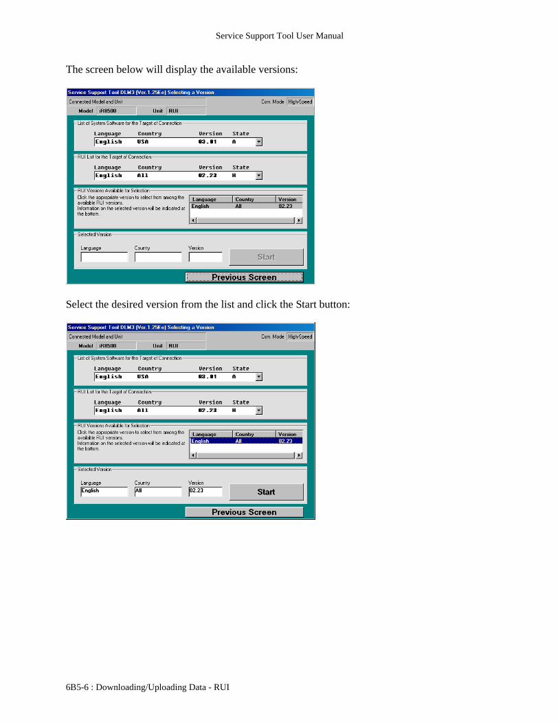
The screen below will display the available versions:
Select the desired version from the list and click the Start button:
6B5-6 : Downloading/Uploading Data - RUI

Service Support Tool User Manual
If an older or identical version of software is selected (compared to that installed on the machine),an extra message is displayed. An example for identical software is shown below:
Data transfer will commence after hitting Start and will be shown as follows:
Downloading/Uploading Data - RUI : 6B5-7

Service Support Tool User Manual
Once data transfer is complete, additional processing is performed on the machine and thefollowing will be displayed as this is done (please see note at beginning of Downloading/Uploading section with regard to this screen and the time displayed):
Once the additional processing is done, checksums will be compared and the following will bedisplayed – click OK to continue:
6B5-8 : Downloading/Uploading Data - RUI

Service Support Tool User Manual
When exiting out from this section of the Tool, a “Cleanup” screen will be displayed as follows:
Network : The “Cleanup” screen for a Network setup is as follows:
Downloading/Uploading Data - RUI : 6B5-9

Service Support Tool User Manual
6B5-10 : Downloading/Uploading Data - RUI
Service Support Tool User Manual
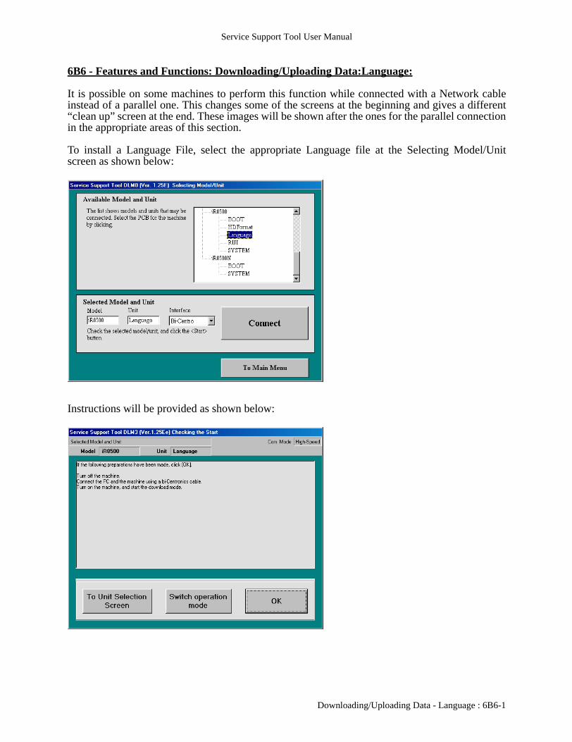
6B6 - Features and Functions: Downloading/Uploading Data:Language:
It is possible on some machines to perform this function while connected with a Network cableinstead of a parallel one. This changes some of the screens at the beginning and gives a different“clean up” screen at the end. These images will be shown after the ones for the parallel connectionin the appropriate areas of this section.
To install a Language File, select the appropriate Language file at the Selecting Model/Unitscreen as shown below:
Instructions will be provided as shown below:
Downloading/Uploading Data - Language : 6B6-1

Service Support Tool User Manual
Network : To perform this function while connected via a Network cable, first select theappropriate Language file and then change the Interface setting from Bi-Centronics to Network asshown below:
Network : For a Network connection to function properly, the computer and machine need to beconnected through an Ethernet Hub or a Cross-Over Cable. Both the computer and the machineneed to have TCP/IP enabled and configured with TCP/IP addresses that are of the same style sothe devices will communicate on the same segment. Basic instructions will be provided as shownbelow – click on Set host name to continue:
6B6-2 : Downloading/Uploading Data - Language
Service Support Tool User Manual
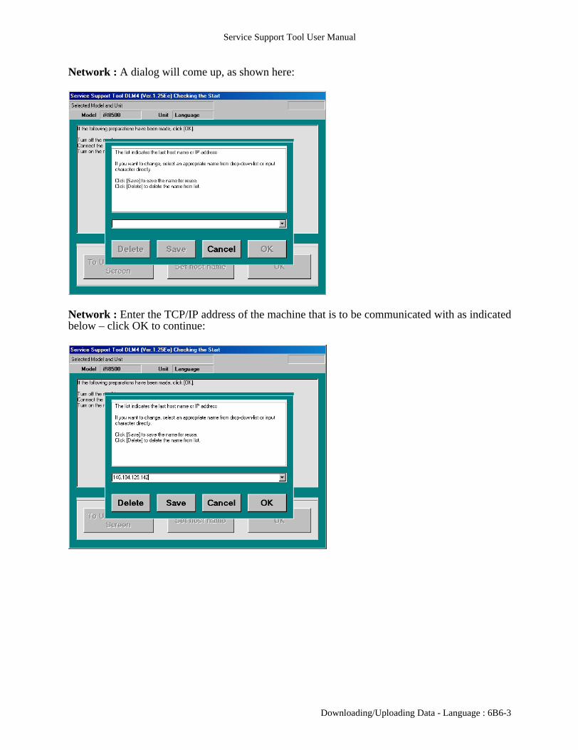
Network : A dialog will come up, as shown here:
Network : Enter the TCP/IP address of the machine that is to be communicated with as indicatedbelow – click OK to continue:
Downloading/Uploading Data - Language : 6B6-3

Service Support Tool User Manual
Network : This will return to the screen shown below. Click OK to continue:
The Service Support Tool will obtain some information from the machine, as shown below:
6B6-4 : Downloading/Uploading Data - Language

Service Support Tool User Manual
Afterwards, the following connection screen will be displayed – click OK to continue:
The following display is for selecting the task to perform – click Language Download to continue:
Downloading/Uploading Data - Language : 6B6-5

Service Support Tool User Manual
The screen below will display the available versions:
Select the desired version from the list and click the Start button:
6B6-6 : Downloading/Uploading Data - Language

Service Support Tool User Manual
If an older or identical version of software is selected (compared to that installed on the machine),an extra message is displayed. An example for identical software is shown below:
Data transfer will commence after hitting Start and will be shown as follows:
Downloading/Uploading Data - Language : 6B6-7

Service Support Tool User Manual
Once data transfer is complete, additional processing is performed on the machine and thefollowing will be displayed as this is done (please see note at beginning of Downloading/Uploading section with regard to this screen and the time displayed):
Once the additional processing is done, checksums will be compared and the following will bedisplayed – click OK to continue:
6B6-8 : Downloading/Uploading Data - Language

Service Support Tool User Manual
When exiting out from this section of the Tool, a “Cleanup” screen will be displayed as follows:
Network : The “Cleanup” screen for a Network setup is as follows:
Downloading/Uploading Data - Language : 6B6-9

Service Support Tool User Manual
6B6-10 : Downloading/Uploading Data - Language

Service Support Tool User Manual
6B7 - Features and Functions: Downloading/Uploading Data:Serial Downloading using the Downloader PCB:
Some devices, such as the Finisher-J1 and the DADF-H1, will require the use of the DownloaderPCB (FY9-2034-000). This device provides a serial (RS232C) connection for flashing. TheDownloader PCB is shown below:
The example in this section will be specifically for a Finisher-J1, but the procedure would followfor any device that utilizes the Downloader PCB.
First, power off all devices and remove the appropriate covers to gain access to the PCB to beflashed. Then, connect the Downloader PCB to both the PC (via RS-232C cable) and the device tobe flashed (for the Finisher-J1 this would be with Cable B to J12 on the Finisher-J1 PCB). Afterconnecting both cables, power on the PC and start the copier in the appropriate download mode(for the Finisher-J1 this would be holding down the 2 & 8 buttons at startup until “DownloadMode” is displayed on the LCD). Please refer to the Device Specific Notes section of this manualfor any device specific information and details.
When the unit is powered on, the power indicator of the Downloader PCB should be on.
Now start the Service Support Tool and proceed to the Downloading/Uploading section to get tothe Selecting Model/Unit screen.
[5] [8] [1] [2] [3] [4] [7] [6] Figure 2-1
Ref. Name
[1] START/STOP button
[2] LOAD LED
[3] Model indicator LED
[4] Power indicator LED
[5] RS-232C cable
[6] Cable A (9-pin; about 70 cm in length)
[7] Cable B (7-pin; about 50 cm in length)
[8] RS-232C connector
Downloading/Uploading Data - Downloader PCB : 6B7-1

Service Support Tool User Manual
From the Selecting Model/Unit screen, select the appropriate file (in this example, the CPU forFinisher-J1) as shown below:
Instructions will appear as follows:
At this point, press the Start/Stop button on the Downloader PCB and verify that the Start LEDturns on. Click OK in the Service Support Tool to continue.
6B7-2 : Downloading/Uploading Data - Downloader PCB
Service Support Tool User Manual
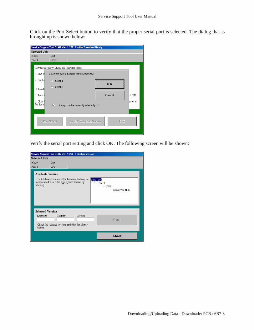
Click on the Port Select button to verify that the proper serial port is selected. The dialog that isbrought up is shown below:
Verify the serial port setting and click OK. The following screen will be shown:
Downloading/Uploading Data - Downloader PCB : 6B7-3

Service Support Tool User Manual
Select the desired version and click Start to continue:
First, the communication between the computer and the target is adjusted:
6B7-4 : Downloading/Uploading Data - Downloader PCB

Service Support Tool User Manual
Next, information is transferred to the target:
If necessary, the Tool will wait for the machine:
Downloading/Uploading Data - Downloader PCB : 6B7-5
Service Support Tool User Manual
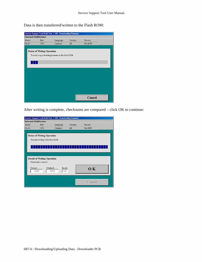
Data is then transferred/written to the Flash ROM:
After writing is complete, checksums are compared – click OK to continue:
6B7-6 : Downloading/Uploading Data - Downloader PCB

Service Support Tool User Manual
When exiting from this section of the Tool, a “Cleanup” screen will be displayed as shown below:
At this point, press the Start/Stop button on the Downloader PCB and verify that the Start LED isoff. Power off both the PC and the unit, disconnect the cables and reinstall the covers.
Downloading/Uploading Data - Downloader PCB : 6B7-7

Service Support Tool User Manual
6B7-8 : Downloading/Uploading Data - Downloader PCB

Service Support Tool User Manual
6B8 - Features and Functions: Downloading/Uploading Data:G3 Fax:
It is possible on some machines to perform this function while connected with a Network cableinstead of a parallel one. This changes some of the screens at the beginning and gives a different“clean up” screen at the end. These images will be shown after the ones for the parallel connectionin the appropriate areas of this section.
From the Selecting Model/Unit screen, select the appropriate G3 Fax as shown below:
Instructions will be provided as shown below:
Downloading/Uploading Data - G3 Fax : 6B8-1
Service Support Tool User Manual
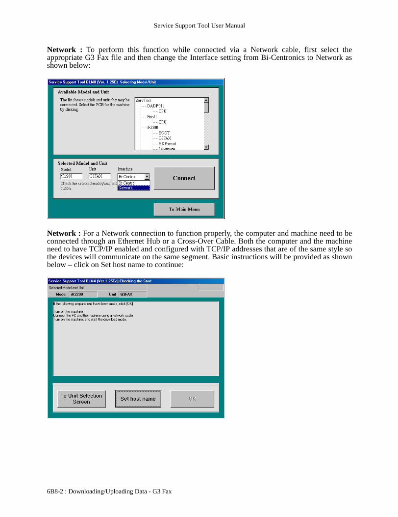
Network : To perform this function while connected via a Network cable, first select theappropriate G3 Fax file and then change the Interface setting from Bi-Centronics to Network asshown below:
Network : For a Network connection to function properly, the computer and machine need to beconnected through an Ethernet Hub or a Cross-Over Cable. Both the computer and the machineneed to have TCP/IP enabled and configured with TCP/IP addresses that are of the same style sothe devices will communicate on the same segment. Basic instructions will be provided as shownbelow – click on Set host name to continue:
6B8-2 : Downloading/Uploading Data - G3 Fax

Service Support Tool User Manual
Network : A dialog will come up, as shown here:
Network : Enter the TCP/IP address of the machine that is to be communicated with as indicatedbelow – click OK to continue:
Downloading/Uploading Data - G3 Fax : 6B8-3

Service Support Tool User Manual
Network : This will return to the screen shown below. Click OK to continue:
The Service Support Tool will obtain some information from the machine, as shown below:
6B8-4 : Downloading/Uploading Data - G3 Fax

Service Support Tool User Manual
After the information is obtained, the following connection screen will be displayed – click OK tocontinue:
The following display is for selecting a task to perform – click G3 Fax Download to continue:
Downloading/Uploading Data - G3 Fax : 6B8-5
Service Support Tool User Manual
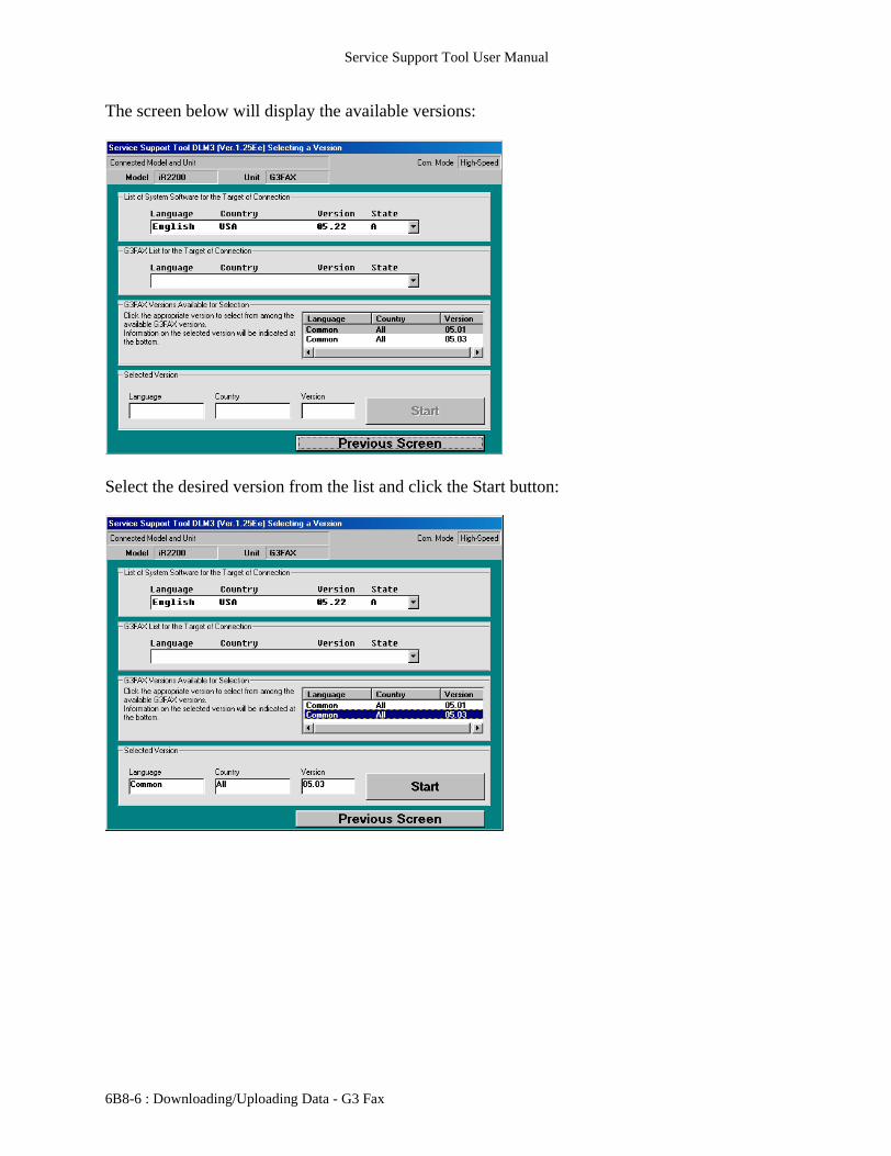
The screen below will display the available versions:
Select the desired version from the list and click the Start button:
6B8-6 : Downloading/Uploading Data - G3 Fax

Service Support Tool User Manual
If the file being sent is older or the same version, an extra dialog will appear. The following is anexample of the same version as installed being resent:
Data will then be transferred and progress is displayed as follows:
Downloading/Uploading Data - G3 Fax : 6B8-7
Service Support Tool User Manual
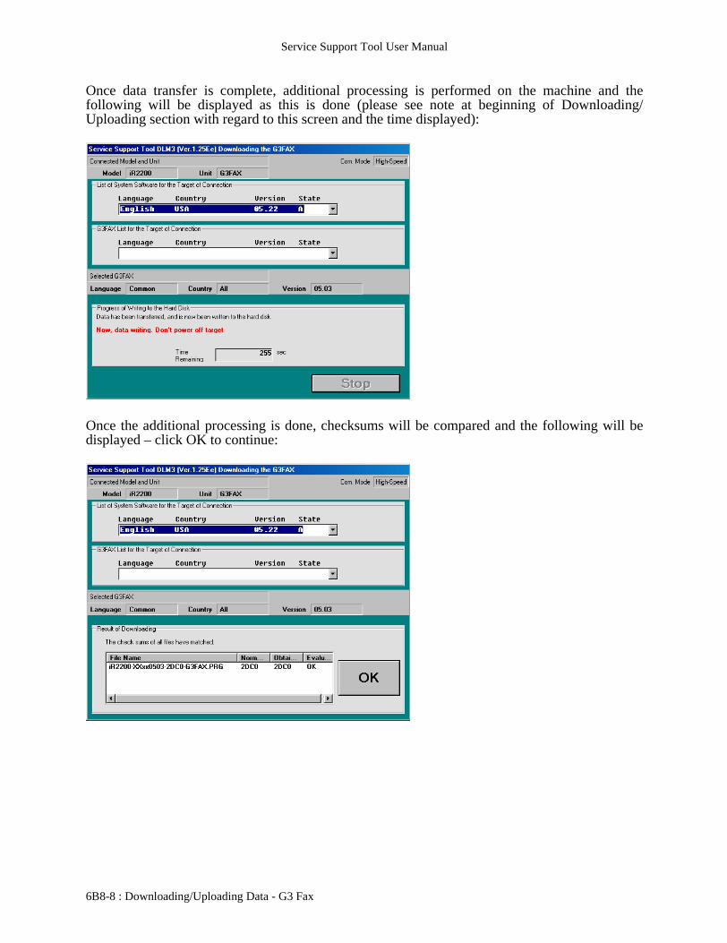
Once data transfer is complete, additional processing is performed on the machine and thefollowing will be displayed as this is done (please see note at beginning of Downloading/Uploading section with regard to this screen and the time displayed):
Once the additional processing is done, checksums will be compared and the following will bedisplayed – click OK to continue:
6B8-8 : Downloading/Uploading Data - G3 Fax
Service Support Tool User Manual
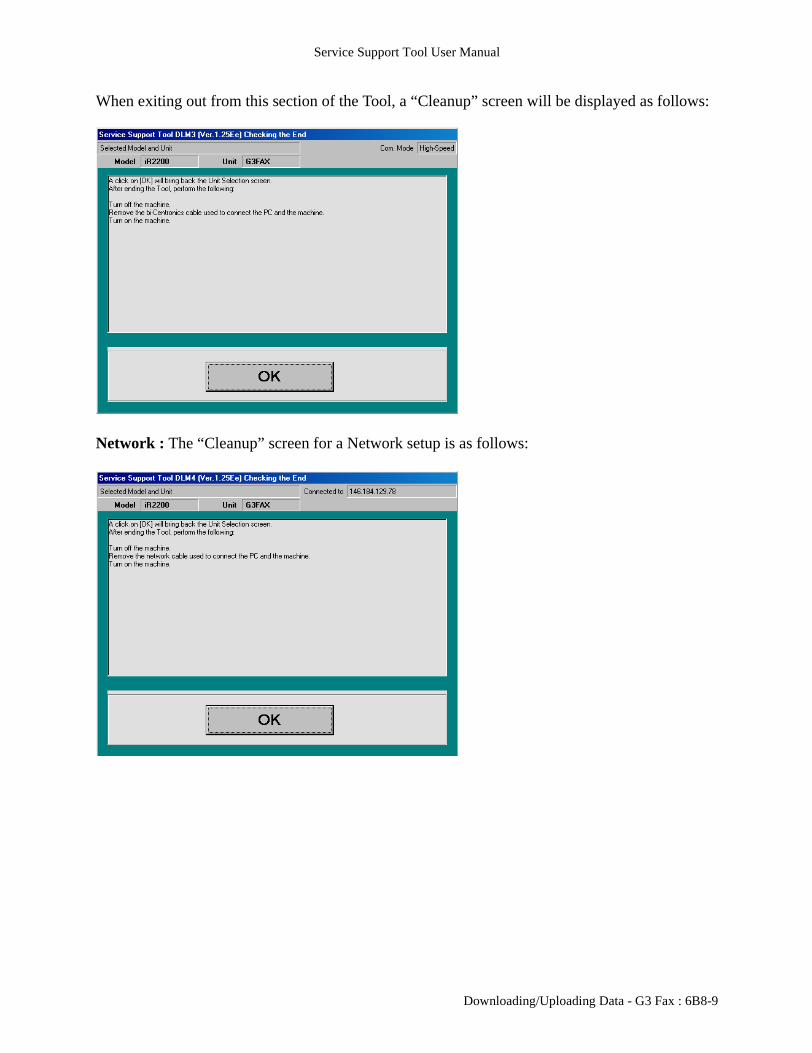
When exiting out from this section of the Tool, a “Cleanup” screen will be displayed as follows:
Network : The “Cleanup” screen for a Network setup is as follows:
Downloading/Uploading Data - G3 Fax : 6B8-9

Service Support Tool User Manual
6B8-10 : Downloading/Uploading Data - G3 Fax

Service Support Tool User Manual
De SB
im oim(M
o
im oim sFin oim oG3(S(TgeBo
o
DA(us
o
im oG3 oDA(us
o
iR oim(ol(S
o
(ol(S(Tinsfun
o
im(ne
o
im oim oim oim oim oim o
7 - Device Specific Notes:
This section will provide some information with regard to using the Service Support Tool withcertain specific devices. The following tables show which devices are supported in which of thedownload modes:
Monochrome Products
vice Serial(Downloader
PCB)
Parallel Network(Ethernet-TCP/IP)
U
Low SpeedMode
High SpeedMode
ageRUNNER 330/400 No Yes No No NageRUNNER 400Sonterey Blue Panel)
No Yes No No N
ageRUNNER 550/600/60 No Yes No No NageRUNNER 1600/2000 No No No No Yeisher-L1 (using Downloader PCB) Yes No No No N
ageRUNNER 2200/2800/3300 No Yes Yes Yes N Fax
ystem Software 6.01 and later)his version MUST be installed to t flash capability for the G3 Fax ard)
No Yes Yes Yes N
DF-H1, Finisher-J1ing Downloader PCB)
Yes No No No N
ageRUNNER 3300i No Yes Yes Yes N Fax No Yes Yes Yes NDF-H1, Finisher-J1ing Downloader PCB)
Yes No No No N
3250 No Yes Yes Yes NageRUNNER 5000 d Main Controller)ystem Software prior to 11.03)
No Yes Yes No N
d Main Controller)ystem Software 11.03 and later)his version MUST already be talled to get Network download ctionality)
No Yes Yes Yes N
ageRUNNER 5000w Main Controller)
No Yes Yes Yes N
ageRUNNER 5000i No Yes Yes Yes NageRUNNER 6000 No Yes Yes Yes NageRUNNER 7200 No Yes Yes Yes NageRUNNER 85 No Yes Yes Yes NageRUNNER 8500 No Yes Yes Yes NageRUNNER 105 No Yes Yes Yes N
Device Specific Notes : 7-1

Service Support Tool User Manual
D
iCCCC
Color Products
Some devices share common data files across many models. Therefore the Model Name that thefirmware is registered under may not exactly match the model being updated. The following tablelists these models and what Model Name they will be registered under. The multiple versions ofimageRUNNER 5000 are listed as well for clarification.
*Note: There are three file types for the Color imageRUNNER machines. These are D-CON, R-CON and S-CON. Only the D-CON file is specific to either a Color imageRUNNER C2050 or aColor imageRUNNER C2058, while the R-CON and S-CON are the same for both machines.There may be times when one of the common files or the other is registered under a differentmodel than what it will be used for. Please refer to the Color imageRUNNER note at the end ofthis section.
evice Serial(Downloader
PCB)
Parallel Network(Ethernet-TCP/IP)
USB
Low SpeedMode
High SpeedMode
mageCLASS C2100 No Yes No No Noolor imageRUNNER C2050 No Yes No No Noolor imageRUNNER C2058 No Yes No No NoLC 1100 Series No Yes No No NoLC 5000 No Yes No No No
Device Registered Model NameColor imageRUNNER C2050 iR_C2100*Color imageRUNNER C2058 iR_C2105*imageRUNNER 330/400imageRUNNER 400S(Monterey Blue Panel)
iR400_33
imageRUNNER 550/600/60 iR600_60imageRUNNER 1600/2000 iR1600USimageRUNNER 2200/2800/3300 iR2200/iR2200NimageRUNNER 3300i iR2200i/iR2200iNimageRUNNER 5000(old Main Controller)
iR5000/iR5000N
imageRUNNER 5000(new Main Controller)imageRUNNER 6000
iR5000d/iR5000dN
imageRUNNER 5000i iR5000i/iR5000iNimageRUNNER 8500imageRUNNER 85
iR8500/iR8500N
7-2 : Device Specific Notes
Service Support Tool User Manual
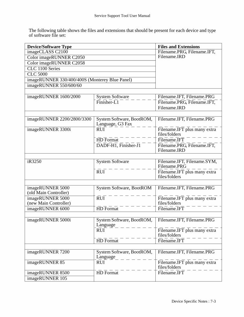
The following table shows the files and extensions that should be present for each device and typeof software file set:
Device/Software Type Files and ExtensionsimageCLASS C2100 Filename.PRG, Filename.IFT,
Filename.IRDColor imageRUNNER C2050Color imageRUNNER C2058CLC 1100 SeriesCLC 5000imageRUNNER 330/400/400S (Monterey Blue Panel)imageRUNNER 550/600/60
imageRUNNER 1600/2000 System Software Filename.IFT, Filename.PRGFinisher-L1 Filename.PRG, Filename.IFT,
Filename.IRD
imageRUNNER 2200/2800/3300 System Software, BootROM, Language, G3 Fax
Filename.IFT, Filename.PRG
imageRUNNER 3300i RUI Filename.IFT plus many extra files/folders
HD Format Filename.IFTDADF-H1, Finisher-J1 Filename.PRG, Filename.IFT,
Filename.IRD
iR3250 System Software Filename.IFT, Filename.SYM, Filename.PRG
RUI Filename.IFT plus many extra files/folders
imageRUNNER 5000(old Main Controller)
System Software, BootROM Filename.IFT, Filename.PRG
imageRUNNER 5000(new Main Controller)
RUI Filename.IFT plus many extra files/folders
imageRUNNER 6000 HD Format Filename.IFT
imageRUNNER 5000i System Software, BootROM, Language
Filename.IFT, Filename.PRG
RUI Filename.IFT plus many extra files/folders
HD Format Filename.IFT
imageRUNNER 7200 System Software, BootROM, Language
Filename.IFT, Filename.PRG
imageRUNNER 85 RUI Filename.IFT plus many extra files/folders
imageRUNNER 8500 HD Format Filename.IFTimageRUNNER 105
Device Specific Notes : 7-3

Service Support Tool User Manual
The following table lists the firmware/software that may be flashed with the Service SupportTool, along with an indication of the method necessary to put the machine in the proper downloadmode:
* Although either mode may be used, HD Format will show different options depending on theselected mode. In Mode B, only the /PDLDEV, /FSTDEV and /DOSDEV partitions can beformatted. In Mode C, the /BOOTDEV partition can be formatted in addition to performing acomplete formatting of the drive. Please refer to the HD Format section of this manual forexamples.
Device Firmware/Software Download ModeimageCLASS C2100 Scanner AColor imageRUNNER C2050 D-CON, R-CON, S-CONColor imageRUNNER C2058CLC 1100 Series M-CON, J-CON, D-CONCLC 5000 D-CON, R-CONimageRUNNER 330/400 IP, D-CONimageRUNNER 400S(Monterey Blue Panel)
IP, D-CON
imageRUNNER 550/600/60 IP, MFC
imageRUNNER 1600/2000 System Software DFinisher-L1(using Downloader PCB)
D
imageRUNNER 2200/2800/3300 System Software, RUI, Language, BootROM, HD Format, G3 Fax
B or C*
imageRUNNER 3300i DADF-H1, Finisher-J1(using Downloader PCB)
C
iR3250 System Software, RUI B
imageRUNNER 5000(old Main Controller)
System Software, RUI B or CBootROM, HD Format C
imageRUNNER 5000(new main Controller)
System Software, RUI, BootROM, HD Format
B or C*
imageRUNNER 6000
imageRUNNER 5000i System Software, RUI, Langauge, BootROM, HD Format
B or C*
imageRUNNER 7200 System Software, RUI, Language, BootROM, HD Format
B or C*imageRUNNER 85imageRUNNER 8500imageRUNNER 105
7-4 : Device Specific Notes

Service Support Tool User Manual
A : Move the small switch next to the appropriate copier parallel port to the position marked“LOAD”. Turn on the copier. The copier display remains unlit (for some models). NOTE : Someunits have multiple parallel ports – confirm that the proper one is being used.
B : Power on machine. Enter Service Mode. Enter Copier -> Function -> System. SelectDownload and hit OK.
C : Power on the machine while holding down the 2 and 8 buttons. Hold 2 and 8 until “DownloadMode” is indicated on the display LCD. NOTE : Network flashing (even if supported) is NOTavailable in this mode as the network functions of the controller have not been activated at thisearly startup stage.
D : Press the “Additional Functions” key, followed by the “# (ID)” key to enter Service Mode.Use the arrow keys on the control panel to select “#11 DOWNLOAD”. Press the ‘OK’ button onthe Control Panel to place the unit into download mode.
imageRUNNER 5000 (old Main Controller) BootROM
There are some extra steps required for flashing an imageRUNNER 5000 BootROM. A secondFDIMM is needed to perform this function. Make sure the machine is powered off. Place thisFDIMM (the FDIMM to be upgraded) into slot J1009 on the Main Controller PCB. The currentBootROM will be (and should now remain) in slot J1010. Start the Download Mode as indicatedabove. Utilize the Service Support Tool to update the BootROM as described in that section ofthis manual. Power off the machine. Remove the FDIMM from slot J1010. Move the FDIMMfrom slot J1009 to slot J1010 to complete the update. The FDIMM that is removed from J1010may be used as the FDIMM for slot J1009 in another update sequence.
imageRUNNER 5000 (old Main Controller) Low Speed Mode
If it is necessary to communicate with the imageRUNNER 5000 in Low Speed mode, then theimageRUNNER 5000 should be started in Download Mode (method C above) for all items.
imageRUNNER 2200/2800/3300/5000/5000i/6000/7200/85/8500/105 Starting in DownloadMode instead of Normal
If the imageRUNNER starts in Download Mode (without holding the keys as in method C above)instead of Normal Mode, it will be necessary to redo installation starting with the HD Format andreinstalling System Software and RUI, if necessary.
Copier vs. Network (N) System Software/BootROM (imageRUNNER 2200/2800/3300/5000(new Main Controller)/6000/7200/85/8500/105)
The above captioned imageRUNNERs ship initially as Copier-only models and need to beupgraded with an appropriate Printer Kit to add Network Printer functionality. Part of this processis the physical replacement of the original BootROM with a Network enabled BootROM(designated with an ‘N’ at the end of the version). Also, a Network version of System Softwaremust be installed. When flash files are registered in the Service Support Tool, they will be registered under themodel name (i.e. iR8500) if they are Copier-only files (such as for the BootROM or SystemSoftware) or files common to both versions (such as the RUI, HD Format and Language). ForNetwork versions of the BootROM and System Software, they will be registered under the modelname with an ‘N’ appended to the end (i.e. iR8500N). While the BootROM and System Software can be updated in the imageRUNNER, they can only
Device Specific Notes : 7-5

Service Support Tool User Manual
be updated with files of the same type (with or without an ‘N’) and BootROM and SystemSoftware must match for the imageRUNNER to operate – with one exception. In the process ofperforming a Network upgrade, the BootROM should be replaced first. The ‘N’ BootROM willsupport an imageRUNNER starting with Copier System Software. This is done to allow use of theimageRUNNER (in Copier-only mode) if there is a wait time until the System Software can beinstalled. Once the Network System Software is installed, the update is complete. Once animageRUNNER has a matched set of BootROM and System Software, both can be flashed in theimageRUNNER to newer versions of the same type (with or without ‘N’).NOTE : If a Copier-only BootROM is installed in an imageRUNNER with Network SystemSoftware already installed, an E677 error will be displayed on startup. Despite the ‘N’ BootROM supporting an imageRUNNER starting with Copier System Software,the ‘N’ BootROM will NOT support flashing Copier System Software (only flashing of NetworkSystem Software) – again with one exception. Some imageRUNNER models support internal andexternal controllers (i.e. imageRUNNER 8500 with Printer Kit-B3 (Internal) and the imagePASS-M1 (External)). When Printer Kit-B3 is used, the system works as previously described.However, when the imagePASS-M1 is used, the system is a little different. To allow for an“upgrade” to the imagePASS from a unit with Printer Kit-B3 already installed, there is a methodto allow an ‘N’ BootROM (which would have been installed with the Printer Kit-B3) to permitthe flashing of Copier System Software onto the imageRUNNER. This is achieved with acombination of updated firmware files (the flash files for the Service Support Tool) and anupdated Service Support Tool application (v1.32 or later).
Color imageRUNNER C2050 vs Color imageRUNNER C2058
There are several differences between the Color imageRUNNER C2050 and the ColorimageRUNNER C2058. A main one is the Printer Board. The Color imageRUNNER C2050introduced the Color Network Printer Board-A1 and the Color imageRUNNER C2058 introducesthe Color Network Printer Board-B1. The Color Network Printer Board-B1 may also be used inthe Color imageRUNNER C2050, if the Color imageRUNNER C2050 firmware values (D-CON/R-CON/S-CON) are at the proper level. With respect to the two models, the R-CON and S-CONare the same, so the files are common to both models – even though they may register in theService Support Tool under one model or the other. The D-CONs, however, are unique to eachmodel. This is due to some of the other differences between a Color imageRUNNER C2050 and aColor imageRUNNER C2058. Always make sure that the proper D-CON file is being utilized.Under the Service Support Tool, the files for a Color imageRUNNER C2050 register underiR_C2100 and the files for a Color imageRUNNER C2058 register under iR_C2105.For each model, there will be separate D-CON files. All older R-CON and S-CON files registeredunder iR_C2100 (for the Color imageRUNNER C2050). Currently, newer R-CON files continueto be registered under iR_C2100 while newer S-CON files are registered under iR_C2105. At thepresent time, regardless of where the R-CON and S-CON files are registered, they may be used onboth models. Where the files are registered, as well as interoperability, may change in the future.
7-6 : Device Specific Notes

Service Support Tool User Manual
imageRUNNER 1600/2000 USB Flashing
There are two USB connectors on the imageRUNNER 1600/2000 models. One is external (on theoptional Printer Board) and is ONLY for USB printing. The USB connector for flashing is on theIP PCB and is J3/J203. The small rectangular plate on the rear of the unit must be removed toaccess this connector. This connector is also used for the optional Ethernet board to plug into.Therefore, if the Ethernet board is installed, there will already be a USB cable attached to J3/J203.This cable must be removed from J3/J203 so that the USB cable that will be used for flashing maybe installed. The USB cable from the Ethernet board should be reinstalled after flashing iscomplete.During the flashing process, there will be a time when the lights on the Control Panel are turnedon and the imageRUNNER will reboot itself. This is normal. During this time, the ServiceSupport Tool will still be on a “countdown” screen. This screen will continue until it reaches zero,at which point the checksum screen will appear. Before the Service Support Tool counts down tozero, the imageRUNNER will reboot and Windows will present an “Add New Hardware” screen.Just press ‘Cancel’.
Device Specific Notes : 7-7

Service Support Tool User Manual
7-8 : Device Specific Notes


