Embed Size (px)
Citation preview

Product Specifications
PSS 1-6H4 A en
Equipment should be installed, operated, serviced, and maintained only by qualified personnel.No responsibility is assumed by Schneider Electric for any consequences arising from the use of this material.
Model 9500A Magnetic Flow Tube
The 9500A magnetic flow tube can be used with IMT30A, IMT31A and IMT33A magnetic flow transmitters.
For all water and wastewater applicationsWide range of approvals for potable waterRobust, fully welded construction

CONTENTS
2 www.se.com PSS 1-6H4 A en - FEBRUARY 2020
9500A
1 Product features 3
1.1 Reliable solution for the water and wastewater industry ............................................... 31.2 Options.............................................................................................................................. 51.3 Measuring principle.......................................................................................................... 7
2 Technical data 8
2.1 Technical data................................................................................................................... 82.2 Measuring accuracy ....................................................................................................... 142.3 Pressure derating........................................................................................................... 152.4 Vacuum load ................................................................................................................... 172.5 Dimensions and weights ................................................................................................ 18
3 Model code 22
4 Notes 25

PRODUCT FEATURES 1
3
9500A
www.se.comPSS 1-6H4 A en - FEBRUARY 2020
1.1 Reliable solution for the water and wastewater industry
The 9500A9500A9500A9500A is designed to meet the demands for all water and waste water applications including groundwater, potable water, waste water, sludge and sewage, industry water and salt water.
The 9500A has a field proven and unsurpassed lifetime. This is assured by the fully welded construction, full bore pipe, absence of moving parts and wear resistant liner materials. The sensor has the widest diameter range available in the market: from DN25 up to DN2000(DN3000 available on request).
1 Robust fully welded construction2 Diameter range: DN25...DN20003 PP, PO and hard rubber liners

1 PRODUCT FEATURES
4
9500A
www.se.com PSS 1-6H4 A en - FEBRUARY 2020
Highlights• Rugged liners suitable for any water and wastewater application• Proven and unsurpassed lifetime, huge installed base• Tamper proof, fully welded construction, also available in customer specific constructions• Drinking water approvals including KTW, KIWA, ACS, DVGW, NSF, WRAS• Suitable for subsoil installation and constant flooding (IP68)• Bi-directional flow metering• Standard in house wet calibration of sensors up to diameter DN2000• Easy installation and commissioning• No grounding rings with virtual reference option on IMT33A• Extensive diagnostic capabilities• Maintenance-free
Industries • Water• Wastewater• Pulp & Paper• Minerals & Mining• Iron, Steel & Metals• Power
Applications• Water abstraction• Water purification and desalination• Drinking water distribution networks• Leakage detection• Irrigation• Industry water• Cooling water• Wastewater• Sewage and sludge• Sea water

PRODUCT FEATURES 1
5
9500A
www.se.comPSS 1-6H4 A en - FEBRUARY 2020
1.2 Options
The reliable solution for the water and wastewater industry
From standard to customizedFrom standard to customizedFrom standard to customizedFrom standard to customizedFor easy ordering the standard range of the 9500A covers all popular sizes, flange materials and connections (ASME, EN, JIS, AWWA).
The 9500A is designed to meet the demands for all water and waste water applications including groundwater, potable water, waste water, sludge and sewage, industry water and salt water.
The 9500A has a field proven and unsurpassed lifetime assured by the fully welded housing, full bore pipe construction, absence of moving parts and wear resistant liner materials.

1 PRODUCT FEATURES
6
9500A
www.se.com PSS 1-6H4 A en - FEBRUARY 2020
Easy installationEasy installationEasy installationEasy installationFitting the 9500A is easy with the flanged design and standard ISO insertion lengths. To further ease the operation, the 9500A can be installed without filters and straighteners. Even grounding rings are not required with the patented "Virtual Reference""Virtual Reference""Virtual Reference""Virtual Reference" option on the IMT33A transmitter.
IP68IP68IP68IP68Installation in measurement chambers subject to (constant) flooding is possible with the IP68 rated version. .

PRODUCT FEATURES 1
7
9500A
www.se.comPSS 1-6H4 A en - FEBRUARY 2020
1.3 Measuring principle
An electrically conductive fluid flows inside an electrically insulated pipe through a magnetic field. This magnetic field is generated by a current, flowing through a pair of field coils.Inside of the fluid, a voltage U is generated:U = v * k * B * DU = v * k * B * DU = v * k * B * DU = v * k * B * D
in which:v = mean flow velocityk = factor correcting for geometryB = magnetic field strengthD = inner diameter of flowmeter
The signal voltage U is picked off by electrodes and is proportional to the mean flow velocity v and thus the flow rate Q. A signal transmitter is used to amplify the signal voltage, filter it and convert it into signals for totalizing, recording and output processing.
Figure 1-1: Measuring principle
1 Field coils2 Magnetic field3 Electrodes4 Induced voltage (proportional to flow velocity)

2 TECHNICAL DATA
8
9500A
www.se.com PSS 1-6H4 A en - FEBRUARY 2020
2.1 Technical data
• The following data is provided for general applications. If you require data that is more relevant to your specific application, please contact us or your local sales office.
• Additional information (certificates, special tools, software,...) and complete product documentation can be downloaded free of charge from the website.
Measuring systemMeasuring principle Faraday's law of induction
Application range Electrically conductive fluids
Measured valueMeasured valueMeasured valueMeasured value
Primary measured value Flow velocity
Secondary measured value Volume flow
DesignFeatures Fully welded maintenance-free flow tube.
Large diameter range DN25...2000
Rugged liners approved for drinking water.
Large standard range but also available in customer specific diameter, length and pressure rating.
Modular construction The measurement system consists of a flow tube and a transmitter. It is available as compact and as separate version. Additional information can be found in the documentation of the transmitter.
Compact version With signal transmitter IMT30A: 9500A + IMT30A 4
With signal transmitter IMT31A: 9500A + IMT31A 4
With signal transmitter IMT33A: 9500A + IMT33A 4
Remote version In wall mount version with signal transmitter IMT30A: 9500A + IMT30A N
In wall mount version with signal transmitter IMT31A: 9500A + IMT31A N
In field or wall mount version with signal transmitter IMT33A: 9500A + IMT33A N or H
Nominal diameter With signal transmitter IMT30A: DN25...1200 / 1…48"
With signal transmitter IMT31A: DN25...1200 / 1…48"
With signal transmitter IMT33A: DN25...2000 / 1…80"

TECHNICAL DATA 2
9
9500A
www.se.comPSS 1-6H4 A en - FEBRUARY 2020
Measuring accuracyMaximum measuring error IMT30A: down to 0.5% of the measured value ± 1 mm/s
IMT31A: down to 0.3% of the measured value ± 1 mm/s
IMT33A: down to 0.2% of the measured value ± 1 mm/s
The maximum measuring error depends on the installation conditions.
For detailed information refer to Measuring accuracy on page 14.
Repeatability ± 0.1% of the measured value, minimum 1 mm/s
Calibration / Verification Standard:Standard:Standard:Standard:
2 point calibration by a direct volume comparison.
Operating conditionsTemperatureTemperatureTemperatureTemperature
For detailed information in pressure / temperature refer to Pressure derating on page 15.
For Ex versions different temperatures are valid. Please refer to the relevant Ex documentation for details.
Process temperature Hard rubber liner: -5...+80°C / +23...+176°F
Polypropylene liner: -5...+90°C / +23...+194°F
Polyolefin liner: -5...+80°C / +23...+176°F
Ambient temperature StandardStandardStandardStandard (with aluminum signal transmitter housing): standard flanges
-20…+65°C / -4…+149°F
OptionOptionOptionOption (with aluminum signal transmitter housing): low temperature carbon steel flanges or stainless steel flanges
-40…+65°C / -40…+149°F
OptionOptionOptionOption (with stainless steel signal transmitter housing): low temperature carbon steel flanges or stainless steel flanges
-40...+55°C / -40…+130°F
Protect electronics against self-heating at ambient temperatures above +55°C / +131°F.
Storage temperature -50...+70°C / -58...+158°F
Measuring rangeMeasuring rangeMeasuring rangeMeasuring range -12...+12 m/s / -40...+40 ft/s

2 TECHNICAL DATA
10
9500A
www.se.com PSS 1-6H4 A en - FEBRUARY 2020
PressurePressurePressurePressure
For detailed information in pressure / temperature refer to Pressure derating on page 15.
EN 1092-1
DN1200...2000: PN 6
DN200...1000: PN 10
DN65 and DN100...150: PN 16
DN25...50 and DN80: PN 40
ASME B16.5 1...24": 150 & 300 lb RF
JIS DN50...1000 / 2...40": 10 K
DN25...40 / 1...1½": 20 K
AWWA (class B or D FF)
Option:Option:Option:Option:
DN700...1000 / 28...40": ≤ 10 bar / 145 psi
DN1200...2000 / 48...80": ≤ 6 bar / 87 psi
DIN PN 16 - 6 bar rated; DN700...2000
PN 10 - 6 bar rated; DN700...2000
PN 6 - 2 bar rated; DN700...2000
Vacuum load For detailed information refer to Vacuum load on page 17.
Pressure loss Negligible
Chemical propertiesChemical propertiesChemical propertiesChemical properties
Physical condition Electrically conductive liquids
Electrical conductivity Standard: ≥ 5 µS/cm
Demineralised water: ≥ 20 µS/cm
Permissible gas content (volume) IMT30A: ≤ 3%
IMT31A: ≤ 3%
IMT33A: ≤ 5%
Permissible solid content (volume)
IMT30A: ≤ 10%
IMT31A: ≤ 10%
IMT33A: ≤ 70%

TECHNICAL DATA 2
11
9500A
www.se.comPSS 1-6H4 A en - FEBRUARY 2020
Installation conditionsInstallation Assure that the flow tube is always fully filled.
For detailed information refer to the manual of the flow tube and signal transmitter
Flow direction Forward and reverse
Arrow on flow tube indicates flow direction.
Inlet run ≥ 5 DN
Outlet run ≥ 2 DN
Dimensions and weights For detailed information refer to Dimensions and weights on page 18.
MaterialsFlow tube housing Sheet steel
Measuring tube Austenitic stainless steel
Flanges Carbon steel
Liner Standard:Standard:Standard:Standard:
DN25...150 / 1...6": polypropylene
DN200...2000 / 8...80": hard rubber
Option:Option:Option:Option:
DN25...150 / 1...6": hard rubber
DN200...1000 / 8...40": polyolefin
Protective coating On exterior of the meter: flanges, housing, signal transmitter (compact version) and / or connection box (field version)
Standard: polyurethane coating
Option: subsoil coating, offshore coating
Connection box Only for remote versions
Standard: die-cast aluminum
Option: stainless steel
Measuring electrodes Standard: Hastelloy® C
Option: stainless steel, titanium
Grounding rings Standard: stainless steel
Option: Hastelloy® C, titanium, tantalum
Grounding rings can be omitted with virtual reference option for the signal transmitter IMT33A.
Reference electrode (optional)
Standard: Hastelloy® C
Option: stainless steel, titanium

2 TECHNICAL DATA
12
9500A
www.se.com PSS 1-6H4 A en - FEBRUARY 2020
Process connectionsFlangeFlangeFlangeFlange
EN 1092-1 DN25...2000 in PN 2.5...40
ASME 1…24" in 150 & 300 lb RF
JIS DN25…1000 in 10...20 K
AWWA DN700...2000 in 6...10 bar
Design of gasket surface RF
Electrical connectionsFor full detail refer to the relevant documentation of the transmitter.
Signal cableSignal cableSignal cableSignal cable (remote versions only)
Type A (DS) In combination with the signal transmitter IMT30A, IMT31A and IMT33AIn combination with the signal transmitter IMT30A, IMT31A and IMT33AIn combination with the signal transmitter IMT30A, IMT31A and IMT33AIn combination with the signal transmitter IMT30A, IMT31A and IMT33A
Standard cable, double shielded.Max. length: 600 m / 1968 ft(depends on electrical conductivity and flow tube)
Type B (BTS) Only in combination with the signal transmitter IMT33AOnly in combination with the signal transmitter IMT33AOnly in combination with the signal transmitter IMT33AOnly in combination with the signal transmitter IMT33A
Optional cable, triple shielded.Max. length: 600 m / 1968 ft(depends on electrical conductivity and flow tube)
I/O For full details of I/O options, including data streams and protocols, see technical datasheet of the relevant signal transmitter.

TECHNICAL DATA 2
13
9500A
www.se.comPSS 1-6H4 A en - FEBRUARY 2020
Approvals and certificatesCECECECE
This device fulfils the statutory requirements of the EU directives. The manufacturer certifies successful testing of the product by applying the CE mark.
For full information of the EU directive & standards and the approved certifications; please refer to the EU Declaration of Conformity or the website of the manufacturer.
Hazardous areaHazardous areaHazardous areaHazardous area
ATEX Please check the relevant Ex documentation for details.
Compact version with Compact version with Compact version with Compact version with signal signal signal signal transmitter IMT31Atransmitter IMT31Atransmitter IMT31Atransmitter IMT31A
II 2 GD
Compact version with Compact version with Compact version with Compact version with signal signal signal signal transmitter IMT33Atransmitter IMT33Atransmitter IMT33Atransmitter IMT33A
II 2 GD or II 2(1) GD
Remote versionRemote versionRemote versionRemote version
II 2 GD
FM In combination with In combination with In combination with In combination with signal signal signal signal transmitter IMT33Atransmitter IMT33Atransmitter IMT33Atransmitter IMT33A
Class I, Div. 2, Groups A, B, C and D
Class II, Div. 2, Groups F and G
Class III, Div. 2, Groups F and G
CSA In combination with In combination with In combination with In combination with signal signal signal signal transmitter IMT33Atransmitter IMT33Atransmitter IMT33Atransmitter IMT33A
Class I, Div. 2, Groups A, B, C and D
Class II, Div. 2, Groups F and G
Other approvals and standardsOther approvals and standardsOther approvals and standardsOther approvals and standards
Drinking water approvals Hard rubber liner: NSF / ANSI standard 61 / ACS, KTW(<60°C), DVGW-W270,KIWA on request.
Polypropylene liner: ACS, KIWA/ATA, KTW, NSF / ANSI standard 61, DVGW-W270, WRAS
Polyolefin liner: ACS, KIWA/ATA, KTW, DVGW-W270, WRAS
Protection category acc. toIEC 60529
Standard:Standard:Standard:Standard:
IP66/67, NEMA 4/4X/6
Option:Option:Option:Option:
IP68, NEMA 6P
IP68 is only available for separate design and with a stainless steel connection box.
Shock test IEC 60068-2-27
30 g for 18 ms
Vibration test IEC 60068-2-64
f = 20...2000 Hz, rms = 4.5 g, t = 30 min

2 TECHNICAL DATA
14
9500A
www.se.com PSS 1-6H4 A en - FEBRUARY 2020
2.2 Measuring accuracy
Every electromagnetic flowmeter is calibrated by direct volume comparison. The wet calibration validates the performance of the flowmeter under reference conditions against accuracy limits.
The accuracy limits of electromagnetic flowmeters are typically the result of the combined effect of linearity, zero point stability and calibration uncertainty.
Reference conditions• Medium: water• Temperature: +5...+35°C / +41...+95°F• Operating pressure: 0.1...5 barg / 1.5...72.5 psig• Inlet section: ≥ 5 DN• Outlet section: ≥ 2 DN
Accuracy
Figure 2-1: Flow velocity vs. accuracyX [m/s] : flow velocityY [%]: deviation from the actual measured value (mv)
Flow tube diameter Signal transmitter type Accuracy Curve
DN25...1200 / 1...48" IMT30A 0.5% of mv + 1 mm/s 1
DN25...1200 / 1...48" IMT31A 0.3% of mv + 1 mm/s 3
DN25...1600 / 1...64" IMT33A 0.2% of mv + 1 mm/s 4
DN1800...2000 / > 64" IMT33A 0.3% of mv + 2 mm/s 2

TECHNICAL DATA 2
15
9500A
www.se.comPSS 1-6H4 A en - FEBRUARY 2020
2.3 Pressure derating
The graphs below refer to the maximum pressure as a function of the temperature for the flanges of the flowmeter (per specified flange material).
Please note that the specified values only refer to the flanges. The maximum value for the flowmeter can further be limited by the maximum value for other materials (i.e. the liner)
For A = Carbon steel A 105 & B = Stainless steel 316L
X/Y axes in all graphs; X = Temperature in [°C] / Y = Pressure in [bar]x/y axes in all graphs; x = Temperature in [°F] / y = Pressure in [psi]
Figure 2-2: Pressure derating; EN 1092-1
1 PN 402 PN 253 PN 164 PN 105 PN 6

2 TECHNICAL DATA
16
9500A
www.se.com PSS 1-6H4 A en - FEBRUARY 2020
Figure 2-3: Pressure derating; ANSI B16.5
1 300 lbs2 150 lbs
Figure 2-4: Pressure derating; JIS B2220
1 20K2 10K

TECHNICAL DATA 2
17
9500A
www.se.comPSS 1-6H4 A en - FEBRUARY 2020
2.4 Vacuum load
Diameter Vacuum load in mbar abs. at a process temperature of
[mm] 20ºC 40ºC 60ºC 80ºC
Hard rubberHard rubberHard rubberHard rubber
DN25...300 250 250 400 400
DN350...1000 500 500 600 600
DN1200...2000 600 600 750 750
PolyolefinPolyolefinPolyolefinPolyolefin
DN200...1000 0 0 0 0
Diameter Vacuum load in psia at process temperature of
[inch] 68ºF 104ºF 140ºF 176ºF
Hard rubberHard rubberHard rubberHard rubber
1...12 3.6 3.6 5.8 5.8
14...40 7.3 7.3 8.7 8.7
48...80 8.7 8.7 10.9 10.9
PolyolefinPolyolefinPolyolefinPolyolefin
8...40 0 0 0 0
2 TECHNICAL DATA
18
9500A
www.se.com PSS 1-6H4 A en - FEBRUARY 2020
2.5 Dimensions and weights
Remote versionRemote versionRemote versionRemote version a = 88 mm / 3.5"
b = 139 mm / 5.5" 1
c = 106 mm / 4.2"
Total height = H + a
Compact version with:Compact version with:Compact version with:Compact version with:IMT33AIMT33AIMT33AIMT33A
a = 155 mm / 6.1"
b = 230 mm / 9.1" 1
c = 260 mm / 10.2"
Total height = H + a
Compact version with:Compact version with:Compact version with:Compact version with:IMT31A (0IMT31A (0IMT31A (0IMT31A (0°))))
a = 82 mm / 3.2"
b = 161 mm / 6.3"
c = 257 mm / 10.1" 1
Total height = H + a
Compact version with:Compact version with:Compact version with:Compact version with:IMT31A (45IMT31A (45IMT31A (45IMT31A (45°))))
a = 186 mm / 7.3"
b = 161 mm / 6.3"
c = 184 mm / 2.7" 1
Total height = H + a

TECHNICAL DATA 2
19
9500A
www.se.comPSS 1-6H4 A en - FEBRUARY 2020
Compact version with:Compact version with:Compact version with:Compact version with:stainless steel IMT31A (10stainless steel IMT31A (10stainless steel IMT31A (10stainless steel IMT31A (10°))))
a = 100 mm / 4"
b = 187 mm / 7.36" 1
c = 270 mm / 10.63"
Total height = H + a
Compact version with:Compact version with:Compact version with:Compact version with:IMT30A (10IMT30A (10IMT30A (10IMT30A (10°))))
a = 101 mm / 3.98"
b = 157 mm / 6.18"
c = 260 mm / 10.24" 1
Total height = H + a
1 The value may vary depending on the used cable glands.

2 TECHNICAL DATA
20
9500A
www.se.com PSS 1-6H4 A en - FEBRUARY 2020
EN 1092-1
• All data given in the following tables are based on standard versions of the flow tube only.• Especially for smaller nominal sizes of the flow tube, the signal transmitter can be bigger
than the tube.• Note that for other pressure ratings than mentioned, the dimensions may be different.• For full information on signal transmitter dimensions see relevant documentation.
Nominal size DN [mm]
Dimensions [mm] Approx. weight
[kg]Standard length
ISO Insertion length
H W
25 150 200 140 115 5
32 150 200 157 140 6
40 150 200 166 150 7
50 200 200 186 165 11
65 200 200 200 185 9
80 200 200 209 200 14
100 250 250 237 220 15
125 250 250 266 250 19
150 300 300 300 285 27
200 350 350 361 340 34
250 400 450 408 395 48
300 500 500 458 445 58
350 500 550 510 505 78
400 600 600 568 565 101
450 600 - 618 615 111
500 600 - 671 670 130
600 600 - 781 780 165
700 700 - 898 895 248
800 800 - 1012 1015 331
900 900 - 1114 1115 430
1000 1000 - 1225 1230 507
1200 1200 - 1417 1405 555
1400 1400 - 1619 1630 765
1600 1600 - 1819 1830 1035
1800 1800 - 2027 2045 1470
2000 2000 - 2259 2265 1860
TECHNICAL DATA 2
21
9500A
www.se.comPSS 1-6H4 A en - FEBRUARY 2020
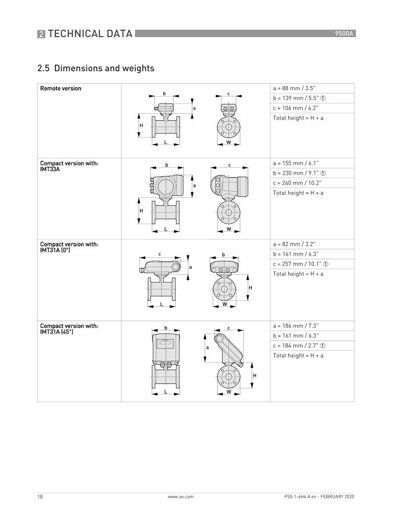
ASME B16.5 / 150 lb flanges
ASME B16.5 / 300 lb flanges
Nominal size [inch]
Dimensions [inch] Approx. weight
[lb]L H W
1" 5.91 5.39 4.25 9
1¼" 5.91 5.75 4.63 13
1½" 5.91 6.10 5.00 15
2" 7.87 7.05 5.98 18
2½" 7.87 7.72 7 22
3" 7.87 8.03 7.50 26
4" 9.84 9.49 9.00 44
5" 9.84 10.55 10.00 49
6" 11.81 11.69 11.00 64
8" 13.78 14.25 13.50 95
10" 15.75 16.30 16.00 143
12" 19.69 18.78 19.00 207
14" 27.56 20.67 21.00 284
16" 31.50 22.95 23.50 364
18" 31.50 24.72 25.00 410
20" 31.50 26.97 27.50 492
24" 31.50 31.38 32.00 675
Nominal size [inch]
Dimensions [inch] Approx. weight
[lb]L H W
1" 5.91 5.71 4.87 11
1¼" 7.87 6.30 5.25 17
1½" 7.87 6.65 6.13 20
2" 9.84 7.32 6.50 22
2½" 9.84 7.95 7.5 25
3" 9.84 8.43 8.25 31
4" 11.81 10.00 10.00 44
6" 12.60 12.44 12.50 73
8" 15.75 15.04 15.00 157
10" 19.69 17.05 17.50 247
12" 23.62 20.00 20.50 375
14" 27.56 21.65 23.00 474
16" 31.50 23.98 25.50 639
20" 31.50 28.46 30.50 937
24" 31.50 33.39 36.00 1345

3 MODEL CODE
22
9500A
www.se.com PSS 1-6H4 A en - FEBRUARY 2020
Model Description
Schneider Electric Model 9500A Magnetic Flow Tube
9501A951QA951HA9502A952HA9503A9504A9505A9506A9508A9510A9512A9514A9516A9518A9520A9524A9528A9530A9532A9536A9540A9544A9548A9556A9564A9572A9580A
Nominal diameter and linerNominal diameter and linerNominal diameter and linerNominal diameter and linerDN25,1" HardrubberDN32,1¼" HardrubberDN40,1½" HardrubberDN50,2" HardrubberDN65,2½" HardrubberDN80,3" HardrubberDN100,4" HardrubberDN125,5" HardrubberDN150,6" HardrubberDN200,8" HardrubberDN250,10" HardrubberDN300,12" HardrubberDN350,14" HardrubberDN400,16" HardrubberDN450,18" HardrubberDN500,20" HardrubberDN600,24" HardrubberDN700,28" HardrubberDN750,30" HardrubberDN800,32" HardrubberDN900,36" HardrubberDN1000,40" HardrubberDN1100,44" HardrubberDN1200,48" HardrubberDN1400,56" HardrubberDN1600,64" HardrubberDN1800,72" HardrubberDN2000,80" Hardrubber
-1-2-3-5-A-B-M-N-4-W
Nominal pressure Nominal pressure Nominal pressure Nominal pressure PN 6 EN 1092-1 (DN1200-2000)PN 10 EN 1092-1 (DN200-2000)PN 16 EN 1092-1 (DN25… 1000) PN 40 EN 1092-1 (DN25...600)150 lbs RF ASME B 16.5 (1" … 24")300 lbs RF ASME B 16.5 (1" … 24")JIS 20 K (DN25 … 40 | 1" … 1 1/2") & (DN200 … 600 |8" … 24")JIS 10 K (DN50 … 1400 | 2" … 56")PN 25 EN 1092-1 (DN200 … 600 )Class D AWWA (DN700 … 2000 | 28" … 80")
0135ACDFTUVWXY
Ex version Ex version Ex version Ex version 1111non ExEEx zone 1 (for IMT33A compact and field, IMT31A compact and wall only)Ex zone 2 (for IMT33A compact and field only)FM Class I DIV 2 (for IMT33A compact and field, IMT31A compact and wall only)cCSAus OL (for IMT33A compact and field, IMT31A compact and wall only)CSA Class I DIV 2 (for IMT33A compact and field, IMT31A compact and wall only)NEPSI zone 1 (for IMT33A compact and field only)IECEx zone 1 (for IMT33A compact and field, IMT31A compact and wall only)BE-Ex EAC (Belarus IMT33A compact and field, IMT31A compact and wall only)RU-Ex EAC (Russia IMT33A compact and field, IMT31A compact and wall only)KA-Ex EAC (Kazakhstan IMT33A compact and field, IMT31A compact and wall only)RU-EAC ( Russia )KA-EAC ( Kazakhstan )BE-EAC ( Belarus )

MODEL CODE 3
23
9500A
www.se.comPSS 1-6H4 A en - FEBRUARY 2020
1
2
3
456ABC
System designSystem designSystem designSystem designCompact/Integral design with aluminum converter housing/cable connections at the transmitterCompact/Integral design with stainless steel converter housing/cable connections at the transmitterModular / withoutSeparate design with aluminum connection box/ ½" NPT cable connections at the transmitterSeparate design with aluminum connection box/ PF ½" cable connectionsSeparate design with aluminum connection box/ M20 x 1.5 A cable connectionsSeparate design with stainless steel connection box/ ½" NPT cable connectionsSeparate design with stainless steel connection box/ PF ½" cable connectionsSeparate design with stainless steel connection box/ M20 x 1.5 cable connections
034CDEKL
Transmitter modelTransmitter modelTransmitter modelTransmitter modelwithout / modularIMT31A (compact design)IMT31A (wall mount version)IMT33A (compact design)IMT33A (field mount version)IMT33A (wall mount version)IMT30A (compact design)IMT30A (wall mount version)
058
LiningLiningLiningLiningStandard (PFA for EEx Zone 1) (Hardrubber DN 200 … 2000)Hardrubber (4...6" / DN100...DN150) Hardrubber (1...3" / DN25...80)
136B
Electrodes (fixed)Electrodes (fixed)Electrodes (fixed)Electrodes (fixed)Stainless steel DIN 1.4571|316 TiHastelloy C4TitaniumHastelloy C22
1Construction of electrodesConstruction of electrodesConstruction of electrodesConstruction of electrodesfixed
134ACD
Housing- / flange materialHousing- / flange materialHousing- / flange materialHousing- / flange materialHousing: steel / Flanges: steel St 37-c22/A105Housing: steel / Flanges: st. steel DIN 1.4404|316 LHousing: steel / Flanges: st. steel: DIN 1.4571/316TiHousing: 1.4301|304 / Flanges: steel St 37-C22 / Flanges: A 105 (with st.st. conn. box.)Housing: 1.4301|304 / Flanges: st. steel DIN 1.4404/316L (with st.st. conn. box.)Housing: 1.4301|304 / Flanges: st. steel DIN 1.4571|316 Ti (with st.st. conn. box.)
012345
Protection class / dimension ( face-to-face )Protection class / dimension ( face-to-face )Protection class / dimension ( face-to-face )Protection class / dimension ( face-to-face )IP66 / 67 / standard dimensionIP68 Field / standard dimension (with stainless steel connection box)IP68 Factory / dimension dimension (with stainless steel connection box)IP66 / 67 / ISO 13359 dimensionIP68 Field / ISO 13359 dimension (with stainless steel connection box)IP68 Factory / ISO 13359 dimension (with stainless steel connection box)
012Y
CableCableCableCableCompact - without / separate DSSeparate BTSSeparate LIYCY (only for FM / CSA Class 1 DIV 2)Without
Model Description

3 MODEL CODE
24
9500A
www.se.com PSS 1-6H4 A en - FEBRUARY 2020
1 Note: to maintain certification, make sure the transmitter being used is listed in the description
012345678Y
Cable lengthCable lengthCable lengthCable lengthCompact - none / separate - 5 m | 15 ft10 m | 30 ft15 m | 45 ft20 m | 60 ft25 m | 75 ft30 m | 90 ft40 m | 120 ft50 m | 150 ft100 m | 300 ftWithout
023R
CalibrationCalibrationCalibrationCalibrationStandard calibrationStandard calibration + 316/1.4401 tag plate (120 x 46 mm)Standard calibration + 316/1.4401 tag plate (67 x 25 mm)Extended calibration (only with IMT30A or IMT31A)
0567ENPR
Ring / MaterialsRing / MaterialsRing / MaterialsRing / MaterialsWithout Ring #1 / TitaniumRing #1 / 1.4404|316 LRing #1 / Hastelloy C22Ring #3 / 1.4404|316 L Protection ring #2 / TitaniumProtection ring #2 / 1.4404|316 LProtection ring #2 / Hastelloy C22
0Construction requirementsConstruction requirementsConstruction requirementsConstruction requirementsStandard
0QA / QC requirementsQA / QC requirementsQA / QC requirementsQA / QC requirementsStandard
0Ratio of CT-calibrationRatio of CT-calibrationRatio of CT-calibrationRatio of CT-calibrationStandard, R = 80
Model Description

NOTES 4
25
9500A
www.se.comPSS 1-6H4 A en - FEBRUARY 2020

4 NOTES
26
9500A
www.se.com PSS 1-6H4 A en - FEBRUARY 2020

NOTES 4
27
9500A
www.se.comPSS 1-6H4 A en - FEBRUARY 2020

PSS 1-6H4 A enPage 28
ORDERING INSTRUCTIONS
FLOWEXPERTPRO SIZING APPLICATION
ADDITIONAL PRODUCTS
1. Model Number.2. Flow Data: a. Maximum, minimum, and normal flow rate. b. Fluid composition and viscosity at operating temperatures. c. Fluid density or relative density (specific gravity). d. Maximum, minimum and normal operating temperatures. e. Maximum, minimum and normal operating pressures. f. Mating pipe schedule. g. Type and location (distance) of upstream disturbance.3. Calibration Information (analog output only); maximum flow rate 20 mA output.4. Electric Classification.5. Optional Selections and Accessories.6. Customer Tag Data.
Websitewww.FlowExpertPro.com
App Store (Apple®) Google PlayTM Store(Android®)
These product lines offer a broad range of measurement and instrument products, including solutions for pressure, flow, analytical,
temperature, positioning, controlling and recording.For a list of these offerings, visit our website at:
www.se.com
Schneider Electric Systems USA, Inc.38 Neponset AvenueFoxboro, MA 02035United States of Americahttp://www.se.com
Copyright 2020 Schneider Electric Systems USA, Inc.All rights reserved.
The Schneider Electric brand and any trademarks of Schneider Electric SE or its subsidiaries are the property of Schneider Electric SE or its subsidiaries.All other trademarks are the property of their respective owners.
FEBRUARY 2020
Global Customer SupportInside U.S.: 1-866-746-6477Outside U.S.: 1-508-549-2424https://pasupport.schneider-electric.com