Embed Size (px)
Citation preview
D-1
Variable displacement vane pumps (with hydraulic pressure compensator)
PSP-Type
Key Features:
Rotation: Right (viewed from shaft end)Mounting flanges: 4-hole flange (UNI ISO 3019/2)Connections: GAS BSP (UNI ISO 228/1) e SAEMechanical displacement limiter "Q" on requestAll pumps are already set up as standard to be coupled to each other and with other types of pumpWide choice of pressure and flow regulation controls
Series/NameRated Displacement
(cm3/r) [in3/r]
Maximum Flow Capacity at 1450 rpm
(L/min) [US gpm]
Maximum Pressure(bar) [psi]
02-PSP-1-20 20 [1.22] 29 [7.66] 160 [2321]02-PSP-1-25 25 [1.53] 36 [9.51] 160 [2321]02-PSP-2-31 31 [1.89] 45 [11.89] 160 [2321]02-PSP-2-40 40 [2.44] 58 [15.32] 160 [2321]02-PSP-2-50 50 [3.05] 73 [19.28] 160 [2321]02-PSP-3-63 63 [3.84] 91 [24.04] 150 [2176]02-PSP-3-80 80 [4.88] 116 [30.64] 150 [2176]
02-PSP-3-100 100 [6.10] 145 [38.30] 150 [2176]
0.5.53.1.03.16.0
D-2
PSPC
ON
TE
NT
S
CONTENTS
GENERAL DESCRIPTION .......................................................................................................................... D-3
CHARACTERISTICS .................................................................................................................................. D-4
ORDERING CODE .................................................................................................................................... D-5
TECHNICAL DATA .................................................................................................................................... D-6
COMBINED PUMPS ................................................................................................................................. D-7
COMBINED PUMPS WITH SINGLE PRESSURE CONTROL DEVICE ............................................................ D-9
PRESSURE-FLOW CONTROL SOLUTIONS ............................................................................................... D-11
CHARACTERISTIC CURVES ..................................................................................................................... D-14
DIMENSIONS ........................................................................................................................................ D-17
ACCESSORIES ........................................................................................................................................ D-22
INSTRUCTIONS FOR INSTALLATION AND USE ....................................................................................... D-24
WARNINGAll Berarma pumps have been carefully checked during manufacture and subjected to stringent testing cycles before shipment. To achieve optimum performance, avoid problems and maintain the warranty, the installation instructions enclosed with each pump must be strictly observed.
NOTESBefore selection or use of any Berarma product, it is important that the purchaser analyses all aspects of its application and reviews the information in the current Berarma Technical-Sales catalogues. Due to the many different operating conditions and applications for Berarma products, the purchaser, through their own analysis and testing, is solely responsible for making the final selection of the products and assuring that all performance and safety requirements are met.
Berarma S.r.l. accepts no responsibility for any editing mistakes in this catalogue.Berarma S.r.l. reserves the right to modify these data without prior notice.
D-3
PSP
GENERAL DESCRIPTION
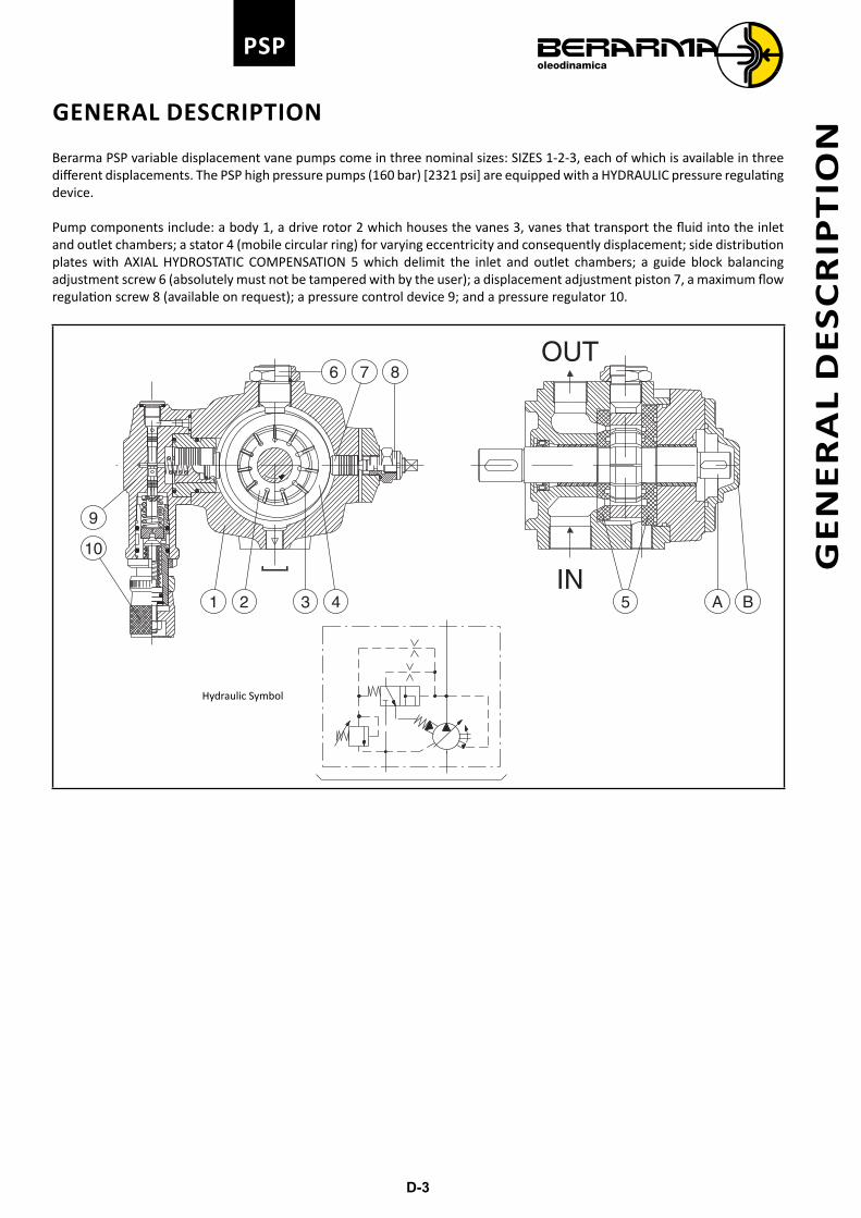
Berarma PSP variable displacement vane pumps come in three nominal sizes: SIZES 1-2-3, each of which is available in three different displacements. The PSP high pressure pumps (160 bar) [2321 psi] are equipped with a HYDRAULIC pressure regulating device.
Pump components include: a body 1, a drive rotor 2 which houses the vanes 3, vanes that transport the fluid into the inlet and outlet chambers; a stator 4 (mobile circular ring) for varying eccentricity and consequently displacement; side distribution plates with AXIAL HYDROSTATIC COMPENSATION 5 which delimit the inlet and outlet chambers; a guide block balancing adjustment screw 6 (absolutely must not be tampered with by the user); a displacement adjustment piston 7, a maximum flow regulation screw 8 (available on request); a pressure control device 9; and a pressure regulator 10.
OUT
IN
9
10
21 43
876
BA5
Hydraulic Symbol
GE
NE
RA
L D
ES
CR
IPT
ION
D-4
PSP
CHARACTERISTICS
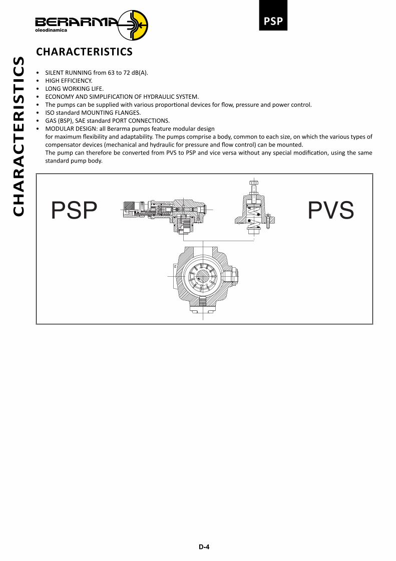
• SILENT RUNNING from 63 to 72 dB(A).• HIGH EFFICIENCY.• LONG WORKING LIFE.• ECONOMY AND SIMPLIFICATION OF HYDRAULIC SYSTEM.• The pumps can be supplied with various proportional devices for flow, pressure and power control.• ISO standard MOUNTING FLANGES.• GAS (BSP), SAE standard PORT CONNECTIONS.• MODULAR DESIGN: all Berarma pumps feature modular design
for maximum flexibility and adaptability. The pumps comprise a body, common to each size, on which the various types of compensator devices (mechanical and hydraulic for pressure and flow control) can be mounted.The pump can therefore be converted from PVS to PSP and vice versa without any special modification, using the same standard pump body.
PVSPSP
IN
CH
AR
AC
TE
RIS
TIC
S
D-5
PSP
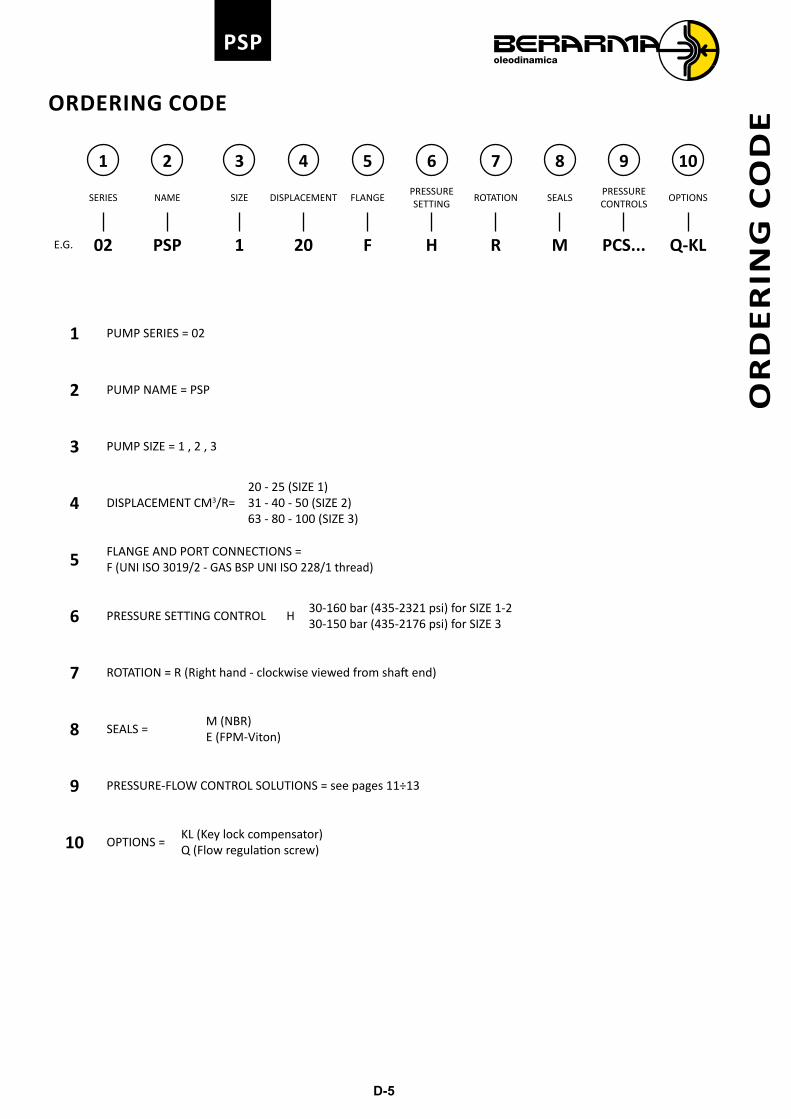
ORDERING CODE
1 2 3 4 5 6 7 8 9 10
SERIES NAME SIZE DISPLACEMENT FLANGEPRESSURE SETTING
ROTATION SEALSPRESSURE CONTROLS
OPTIONS
E.G. 02 PSP 1 20 F H R M PCS... Q-KL
1 PUMP SERIES = 02
2 PUMP NAME = PSP
3 PUMP SIZE = 1 , 2 , 3
4 DISPLACEMENT CM3/R=20 - 25 (SIZE 1)31 - 40 - 50 (SIZE 2)63 - 80 - 100 (SIZE 3)
5 FLANGE AND PORT CONNECTIONS =F (UNI ISO 3019/2 - GAS BSP UNI ISO 228/1 thread)
6 PRESSURE SETTING CONTROL H30-160 bar (435-2321 psi) for SIZE 1-230-150 bar (435-2176 psi) for SIZE 3
7 ROTATION = R (Right hand - clockwise viewed from shaft end)
8 SEALS = M (NBR)E (FPM-Viton)
9 PRESSURE-FLOW CONTROL SOLUTIONS = see pages 11÷13
10 OPTIONS = KL (Key lock compensator)Q (Flow regulation screw)
OR
DE
RIN
G C
OD
E
D-6
PSP
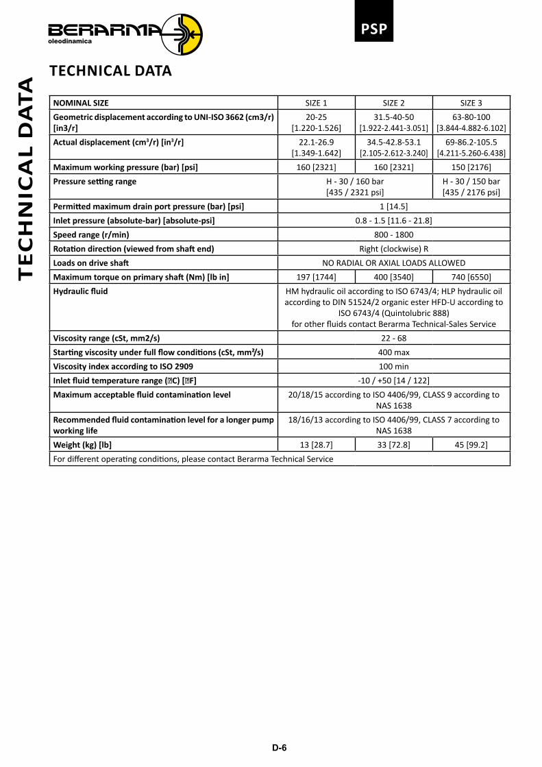
TECHNICAL DATA
NOMINAL SIZE SIZE 1 SIZE 2 SIZE 3
Geometric displacement according to UNI-ISO 3662 (cm3/r) [in3/r]
20-25[1.220-1.526]
31.5-40-50[1.922-2.441-3.051]
63-80-100[3.844-4.882-6.102]
Actual displacement (cm3/r) [in3/r] 22.1-26.9[1.349-1.642]
34.5-42.8-53.1[2.105-2.612-3.240]
69-86.2-105.5[4.211-5.260-6.438]
Maximum working pressure (bar) [psi] 160 [2321] 160 [2321] 150 [2176]
Pressure setting range H - 30 / 160 bar[435 / 2321 psi]
H - 30 / 150 bar[435 / 2176 psi]
Permitted maximum drain port pressure (bar) [psi] 1 [14.5]
Inlet pressure (absolute-bar) [absolute-psi] 0.8 - 1.5 [11.6 - 21.8]
Speed range (r/min) 800 - 1800
Rotation direction (viewed from shaft end) Right (clockwise) R
Loads on drive shaft NO RADIAL OR AXIAL LOADS ALLOWED
Maximum torque on primary shaft (Nm) [lb in] 197 [1744] 400 [3540] 740 [6550]
Hydraulic fluid HM hydraulic oil according to ISO 6743/4; HLP hydraulic oil according to DIN 51524/2 organic ester HFD-U according to
ISO 6743/4 (Quintolubric 888)for other fluids contact Berarma Technical-Sales Service
Viscosity range (cSt, mm2/s) 22 - 68
Starting viscosity under full flow conditions (cSt, mm²/s) 400 max
Viscosity index according to ISO 2909 100 min
Inlet fluid temperature range (C) [F] -10 / +50 [14 / 122]
Maximum acceptable fluid contamination level 20/18/15 according to ISO 4406/99, CLASS 9 according to NAS 1638
Recommended fluid contamination level for a longer pump working life
18/16/13 according to ISO 4406/99, CLASS 7 according to NAS 1638
Weight (kg) [lb] 13 [28.7] 33 [72.8] 45 [99.2]
For different operating conditions, please contact Berarma Technical Service
TE
CH
NIC
AL
DA
TA
D-7
PSP
CO
MB
INE
D P
UM
PS
COMBINED PUMPS
BERARMA pumps are already set up for coupling to one another or to other types of pump (see table of possible combinations). The standard rotor shaft is set up for coupling (see pump section view, detail "A", on page 3).
After removal of cover "B", the pump can be fitted with the different units already set up for coupling.
With this solution BERARMA intends to avoid pumps with non-standard special applications, in order to simplifyinterchangeability and pump combination. For solutions different to the ones described, please contact Berarma Technical Service.
2
1
1) Combined Pumps2) Non return valve - recommended installation (supplied on request)
The ordering code should be specified according to the coupling sequence
PRIMARY PUMP CODE + COUPLING UNIT CODE + SECONDARY PUMP CODE
D-8
PSPC
OM
BIN
ED
PU
MP
S
Combined pumps should be mounted in decreasing order of absorbed power. Depending on the conditions of use of each pump, pump combination should be established after first checking that torque values (Nm) [lb in] never exceed the limits specified in the table below.
Primary pump Secondary pump Coupling unit codeMaximum torque for
secondary pump
02 PVS-PSP 1
Gear pump 1P 3000011000
55 Nm[487 lb in]
Gear pump 1M 3000011100
Gear pump 2 300001120001-PLP-PHV-05-F 3000010200
01-PLP-PHV-05-FGR2 300001120002 PVS-PSP 1 F 3000010100
SAE "A" 3100000100
02 PVS-PSP 2-3
Gear pump 1P 3000022000
110 Nm[974 lb in]
Gear pump 1M 3000022100Gear pump 2 3000022200Gear pump 3 3000022300
01-PLP-PHV-05-F 300002040001-PLP-PHV-05-FGR2 3000022200
02 PVS-PSP 1 F 300002010002 PVS-PSP 2 3000020200
SAE "A" 3100000200SAE "B" 3100000300
02 PVS-PSP 3 02 PVS-PSP 3 3000020300180 Nm
[1593 lb in]
Warning: the sum of the torques of the combined pumps must not exceed the maximum permissible torque on the primary pump (see page 6).
Secondary pump with SAE A or B 2-bolt mounts should conform to the dimensions below.
CØA
D
G
E
F
ØB
Primary pumpSecondary pump
flangeØA ØB C D E min. E max. F G
02 PSP 1 SAE J744 A82.5
[3.248"]19.05
[0.750"]21.1
[0.831"]4.8
[0.189"]32
[1.260"]59
[2.323"]7
[0.276"]106.4
[4.189"]
02 PSP 2-3
SAE J744 A82.5
[3.248"]19.05
[0.750"]21.1
[0.831"]4.8
[0.189"]32
[1.260"]59
[2.323"]7
[0.276"]106.4
[4.189"]
SAE J744 B101.6
[4.000"]22.2
[0.874"]
25.1 [0.988"]
6,375 [0.251"] 41
[1.614"]71
[2.795"]9.5
[0.374"]146
[5.748"]25.5 [1.000"]
4.8 [0.189"]
D-9
PSP
COMBINED PUMPS WITH SINGLE PRESSURE CONTROL DEVICE
In response to market demand, Berarma has widened its range of products to cater to the request for higher displacement pumps in an original way.In fact, rather than developing large displacement pumps as such, Berarma has obtained the same results by combining standard SIZE 3 pumps controlled by a single hydraulic device for pressure regulation.
This solution:• reduces noise level• cuts down production costs
DIMENSIONS
U E
CETOP 03 [UNI ISO 4401-03]
26.6 [1.047]
31 [1.221]
32.5 [1.280]
19 [0
.748
]
40.5
[1.5
95]
6 [0.236]16.3 [0.642]
[0.394]
(BSP)
(BSP)
[0.472]
67 [2.638]
105 [4.134]105 [4.134]
133
[5.2
36]
12 [0.472]
155.
5 [6
.122
]
Ø18 [0.709]
140 [5.512] max.
58.7
[2.3
11]
58.7
[2.3
11]
30.2 [1.189]315 [12.402] 35 [1.378]
30.2 [1.189]
185
[7.2
84]
43 [1
.693
]
120
[4.7
24]
123 [4.843]
185 [7.284]
Ø200 [7.874]
301
[11.
850]
315 [12.402]
10 [0.394]
105 [4.134]
77.8
[3.0
63]
77.8
[3.0
63]
Ø40
[1.5
75]
315 [12.402]560 [22.047]
46 [1.811]
68 [2.677]
43 [1.693] 43 [1.693]
Ø16
0 [6
.299
]
G
D
F 1/4" Gas
BØ32 [1.260]
M10
C3/4" Gas
Ø51 [2.008]A
M12
A - SAE flange inlet port.
B - SAE flange outlet port.
C - GAS (BSP) thread drain port.
D - Pressure regulating knob.Rotate clockwise to increase pressure.
E - Set-up for pressure control system with CETOP 03 [UNI ISO 4401-03] mounting surface.
F - 1/4" GAS (BSP) port connection for pressure gauge.
G - Identification plate.
U - Manifold block, with CETOP 03 [UNI ISO 4401-03] mounting surface, for solenoid operated directional control valve to vent air.
CO
MB
INED
PU
MP
S W
ITH
SIN
GLE
PR
ESSU
RE
CO
NTR
OL
DEV
ICE
D-10
PSPC
OM
BIN
ED P
UM
PS
WIT
H S
ING
LE P
RES
SUR
E C
ON
TRO
L D
EVIC
E
U
V
S
F
CE
TO
P 0
3 [U
NI I
SO
440
1-03
]
T
P
R
For further information, please consult the leaflet "Installation and start-up instructions for PSPC-type variable displacement vane combined pumps with single pressure control device".
Geometric displacement (cm3/r) [in3/r] 126[7.689]
143[8.726]
160[9.764]
180[10.984]
200[12.205]
Actual displacement (cm3/r) [in3/r] 126[7.689]
155.2[9.471]
172.4[10.520]
191.7[11.698]
211[12.876]
R - Combined pumps with single pressure control device.
S - Outlet manifold with check valves and maximum pressure relief valve.Supplied on request. Installation recommended.
F - 1/4" GAS (BSP) port connection for pressure gauge.
U - Manifold block, with CETOP 03 [UNI ISO 4401-03] mounting surface, for solenoid operated directional control valve to vent air.
V - Solenoid operated directional control valve to vent air. Supplied on request (specify coil type). Must be installed in case of starting under zero flow setting conditions.
ORDERING CODE
1 2 3 4 5 6 7 8 9 10
SERIES NAME SIZE DISPLACEMENT FLANGEPRESSURE SETTING
ROTATION SEALSPRESSURE CONTROLS
OPTIONS
E.G. 02 PSPC 3 200 F H R M PCS... KL
1 PUMP SERIES = 02 6 PRESSURE SETTING CONTROL = H 30-120 bar [435-1740 psi]
2 PUMP NAME = PSPC 7 ROTATION = R (Right hand - clockwise viewed from shaft end)
3 PUMP SIZE = 3 8 SEALS = M (NBR)
4 DISPLACEMENT CM3/R = 126, 143, 160, 180, 200 9 PRESSURE-FLOW CONTROL SOLUTIONS page 12
PCS002PCS003PCS004PCS005
5FLANGE AND PORT CONNECTION =F (Flange: UNI ISO 3019/2 Inlet-Outlet port: SAE flange Drain port: GAS BSP UNI ISO 228/1 thread)
10 OPTIONS = KL (Key lock compensator)
D-11
PSP
PRESSURE-FLOW CONTROL SOLUTIONS
PSP pumps can be supplied with a wide range of electro-hydraulic devices for pressure and flow control.In addition to its various pressure regulating systems, Berarma has developed a LOAD-SENSING device for its pumps (see diagrams with characteristic curves).This solution make Berarma pumps suitable to be used in energy saving systems.
LOAD - SENSINGThe LOAD-SENSING flow regulating system is relatively simple; the signal for the compensator is picked up from the pump pressure line after a restriction and before an actuator.The regulating system (restriction) may comprise: throttle, manual or proportional type, or quick/slow units.As the extent of the restriction (at a fixed pressure drop Δp=20 bar [290 psi] [*]) changes, pump displacement is automatically varied by the system regardless of pressure variations in the circuit. The LOAD-SENSING system enables the notable limitation of power dissipation and is particularly suitable for applications with considerable torque (or force) and speed variations.
[*] Note: For different operating conditions, please contact Berarma Technical Service.
6 [0.236]
19 [0
.748
]
16.3 [0.642]
26.6 [1.047]
32.5 [1.280]
31 [1.221]40
.5 [1
.595
]
T P
Mounting surface CETOP-03 [UNI ISO 4401-03] on PCS and PCLS compensators
Note: dimensions inside [ ] are in inches
PR
ES
SU
RE
-FLO
W C
ON
TR
OL
SO
LUT
ION
S
D-12
PSPP
RE
SS
UR
E-F
LOW
CO
NT
RO
L S
OLU
TIO
NS
Diagrams and characteristic curves for pressure regulation
1 Pump with standard pressure compensator
2 Pump with pressure compensator with CETOP 03 [UNI ISO 4401-03]
P CS002
P CS003
P CS004
3Pump with pressure compensator for proportional regulation with CETOP 03 [UNI ISO 4401-03]
P CS005
Pump with two-stage pressure control, one of which is fixed (at the minimum pressure setting of the pump)
Code P CS003
2
A
q
p
A - Solenoid valve supplied only on request (please specify coil type)
Standard pump1
p
q
Pump with two-stage pressure control, both adjustable
Code P CS004
2B A
q
p
A - Berarma pressure relief valve supplied factory-assembled and testedB - Solenoid valve supplied only on request (please specify coil type)
Pump with remote pressure control
Code P CS002
2
A
q
p
A - Maximum pressure relief valve (0-5 l/min) [0-1.32 USgpm] not suppliedNote• The length of the pilot pipe
between the compensator and the valve must not exceed 5 m [16 ft]
• Remote control port 1/4" Gas (BSP) or 1/2"-20 UNF 2B
Pump with proportional pressure control
Code P CS005
3
A
q
pA - Pressure control proportional valve supplied only on request
D-13
PSP
PR
ES
SU
RE
-FLO
W C
ON
TR
OL
SO
LUT
ION
S
Diagrams and characteristic curves for combined LOAD SENSING and pressure regulation
1 LOAD SENSING pump with standard pressure regulation
P CLS001
2LOAD SENSING pump with CETOP 03 mounting surface [UNI ISO 4401-03]
P CLS002-3-4-5
3 Manual-electrical-proportional flow regulator not supplied
Note• The length of the individual pipe between the flow
regulator and the LOAD SENSING device must not exceed 5 m [16 ft]
• Load Sensing signal port 1/4" Gas (BSP) or 1/2"-20 UNF 2B
LOAD SENSING pump with two-stage pressure control, one of which is fixed (at the minimum pressure setting of the pump)
Code P CLS003
2
3
A
q
p
A - Solenoid valve supplied only on request (please specify coil type)
LOAD SENSING pump with standard pressure regulation
Code P CLS001
1
3
q
p
LOAD SENSING pump with two adjustable pressure stages
Code P CLS004
3
2A
B
q
p
A - Berarma pressure relief valve supplied factory-assembled and testedB - Solenoid valve supplied only on request (please specify coil type)
LOAD SENSING pump with remote pressure control
Code P CLS002
3
2A
q
p
A - Maximum pressure relief valve (0-5 l/min) [0-1.32 USgpm] not supplied.Note• The length of the pilot pipe
between the compensator and the valve must not exceed 5 m [16 ft]
• Remote control port 1/4" Gas (BSP) or 1/2"-20 UNF 2B
LOAD SENSING pump with proportional pressure control
Code P CLS005
3
2A
q
pA - Pressure control proportional valve supplied only on request
D-14
PSP
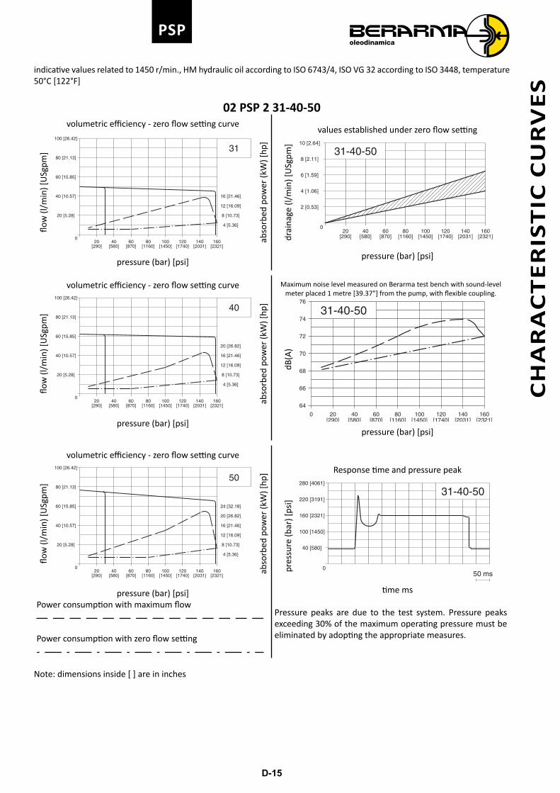
CHARACTERISTIC CURVES
indicative values related to 1450 r/min., HM hydraulic oil according to ISO 6743/4, ISO VG 32 according to ISO 3448, temperature 50°C [122°F].
02 PSP 1 20-25
100[1450][870]
20[290] [580]
40 80[1160]
60[2321]
120[1740]
140[2031]
160
4 [1.06]
5 [1.32]
3 [0.79]
1 [0.26]
2 [0.53]
20-25
0
drai
nage
(l/m
in) [
USg
pm]
pressure (bar) [psi]
values established under zero flow setting
10 [13.41]
8 [10.73]
6 [8.05]
4 [5.36]
2 [2.68]
[2321][2031][1740][1450][1160][870][580][290]
10 [2.64]
20 [5.28]
30 [7.93]
40 [10.57]
50 [13.21]
20
1601401201008060200
40
flow
(l/m
in) [
USg
pm]
pressure (bar) [psi]
volumetric efficiency - zero flow setting curve
abso
rbed
pow
er (k
W) [
hp]
Maximum noise level measured on Berarma test bench with sound-level meter placed 1 metre [39.37"] from the pump, with flexible coupling.
[1450][870] ]1232[]0611[]085[]092[ [1740] [2031]10020 40 8060 120 140 160
72
74
20-25
70
66
68
62
64
dB(A
)
pressure (bar) [psi]
12 [16.09]
10 [13.41]
8 [10.73]
6 [8.05]
4 [5.36]
2 [2.68]
[2321][2031][1740][1450][1160][870][580][290]
10 [2.64]
20 [5.28]
30 [7.93]
40 [10.57]
50 [13.21]
25
1601401201008060200
40
flow
(l/m
in) [
USg
pm]
pressure (bar) [psi]
volumetric efficiency - zero flow setting curve
abso
rbed
pow
er (k
W) [
hp]
Power consumption with maximum flow
Power consumption with zero flow setting
280 [4061]
220 [3191]
160 [2321]
100 [1450]
40 [580]
50 ms
20-25
0pres
sure
(bar
) [ps
i]
time ms
Response time and pressure peak
Pressure peaks are due to the test system. Pressure peaks exceeding 30% of the maximum operating pressure must be eliminated by adopting the appropriate measures.
Note: dimensions inside [ ] are in inches
CH
AR
AC
TE
RIS
TIC
CU
RV
ES
D-15
PSP
indicative values related to 1450 r/min., HM hydraulic oil according to ISO 6743/4, ISO VG 32 according to ISO 3448, temperature 50°C [122°F]
02 PSP 2 31-40-50
160[2321][2031]
14080[1450]100
[1740]12060
[870]40
[580]20
[290] [1160]
20 [5.28]
60 [15.85]
40 [10.57]
100 [26.42]
80 [21.13]
8 [10.73]
4 [5.36]
16 [21.46]
12 [16.09]
31
0
flow
(l/m
in) [
USg
pm]
abso
rbed
pow
er (k
W) [
hp]
pressure (bar) [psi]
volumetric efficiency - zero flow setting curve
160[2321]
120[1740]
100[1450]
140[2031]
8060[870]
20[290]
40[580] [1160]
6 [1.59]
2 [0.53]
4 [1.06]
8 [2.11]
10 [2.64]
0
31-40-50
drai
nage
(l/m
in) [
USg
pm]
pressure (bar) [psi]
values established under zero flow setting
20 [26.82]
160140[2031]
120[1740] [2321]
60[1160]
8040[580][290]
20[870]
100[1450]
16 [21.46]
8 [10.73]
4 [5.36]
12 [16.09]
100 [26.42]
40 [10.57]
60 [15.85]
80 [21.13]
20 [5.28]
40
0
flow
(l/m
in) [
USg
pm]
pressure (bar) [psi]
volumetric efficiency - zero flow setting curve
abso
rbed
pow
er (k
W) [
hp]
Maximum noise level measured on Berarma test bench with sound-level meter placed 1 metre [39.37"] from the pump, with flexible coupling.
160[2031]
140[2321]
80[1160] [1450]
100[870]6040
[580]20
[290] [1740]120
74
76
72
68
70
0
64
66
31-40-50
dB(A
)
pressure (bar) [psi]
24 [32.18]
20 [26.82]
160140[2031]
120[1740] [2321]
60[1160]
8040[580][290]
20[870]
100[1450]
16 [21.46]
8 [10.73]
4 [5.36]
12 [16.09]
100 [26.42]
40 [10.57]
60 [15.85]
80 [21.13]
20 [5.28]
50
0
flow
(l/m
in) [
USg
pm]
pressure (bar) [psi]
volumetric efficiency - zero flow setting curve
abso
rbed
pow
er (k
W) [
hp]
Power consumption with maximum flow
Power consumption with zero flow setting
160 [2321]
100 [1450]
40 [580]
280 [4061]
220 [3191]
50 ms
31-40-50
0pres
sure
(bar
) [ps
i]
time ms
Response time and pressure peak
Pressure peaks are due to the test system. Pressure peaks exceeding 30% of the maximum operating pressure must be eliminated by adopting the appropriate measures.
Note: dimensions inside [ ] are in inches
CH
AR
AC
TE
RIS
TIC
CU
RV
ES
D-16
PSP
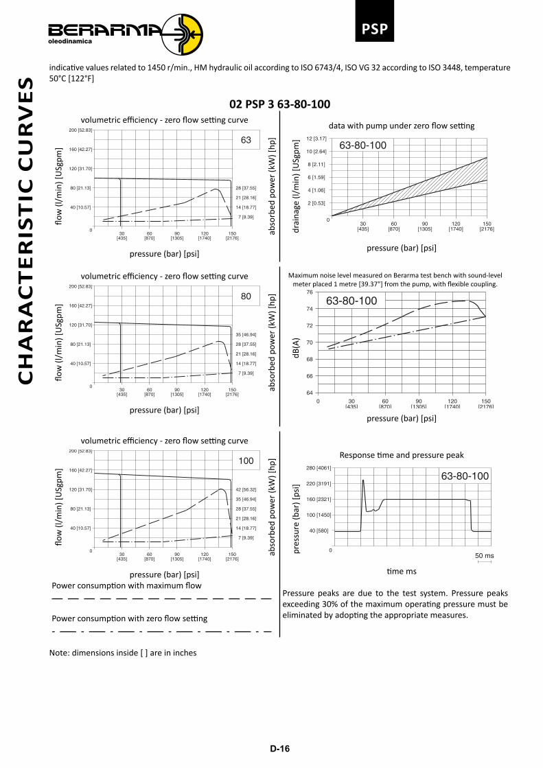
indicative values related to 1450 r/min., HM hydraulic oil according to ISO 6743/4, ISO VG 32 according to ISO 3448, temperature 50°C [122°F]
02 PSP 3 63-80-100
[2176][1740][1305][870][435]150120906030
7 [9.39]
21 [28.16]
14 [18.77]
28 [37.55]
40 [10.57]
160 [42.27]
120 [31.70]
80 [21.13]
200 [52.83]
63
0
flow
(l/m
in) [
USg
pm]
abso
rbed
pow
er (k
W) [
hp]
pressure (bar) [psi]
volumetric efficiency - zero flow setting curve
12 [3.17]
8 [2.11]
6 [1.59]
4 [1.06]
2 [0.53]
10 [2.64]
150120[1740] [2176]
90[1305]
60[870]
30[435]
0
63-80-100
drai
nage
(l/m
in) [
USg
pm]
pressure (bar) [psi]
data with pump under zero flow setting
35 [46.94]
28 [37.55]
7 [9.39]
14 [18.77]
21 [28.16]
150120[1740] [2176]
90[1305]
60[870]
30[435]
200 [52.83]
80 [21.13]
120 [31.70]
160 [42.27]
40 [10.57]
80
0
flow
(l/m
in) [
USg
pm]
pressure (bar) [psi]
volumetric efficiency - zero flow setting curveab
sorb
ed p
ower
(kW
) [hp
]Maximum noise level measured on Berarma test bench with sound-level
meter placed 1 metre [39.37"] from the pump, with flexible coupling.
150[1740]120
[2176][1305]9060
[870]30
[435]
74
76
72
68
70
0
64
66
63-80-100dB
(A)
pressure (bar) [psi]
42 [56.32]
35 [46.94]
28 [37.55]
7 [9.39]
14 [18.77]
21 [28.16]
150120[1740] [2176]
90[1305]
60[870]
30[435]
200 [52.83]
80 [21.13]
120 [31.70]
160 [42.27]
40 [10.57]
100
0
flow
(l/m
in) [
USg
pm]
pressure (bar) [psi]
volumetric efficiency - zero flow setting curve
abso
rbed
pow
er (k
W) [
hp]
Power consumption with maximum flow
Power consumption with zero flow setting
160 [2321]
100 [1450]
40 [580]
280 [4061]
220 [3191]
50 ms
63-80-100
0pres
sure
(bar
) [ps
i]
time ms
Response time and pressure peak
Pressure peaks are due to the test system. Pressure peaks exceeding 30% of the maximum operating pressure must be eliminated by adopting the appropriate measures.
Note: dimensions inside [ ] are in inches
CH
AR
AC
TE
RIS
TIC
CU
RV
ES
D-17
PSP
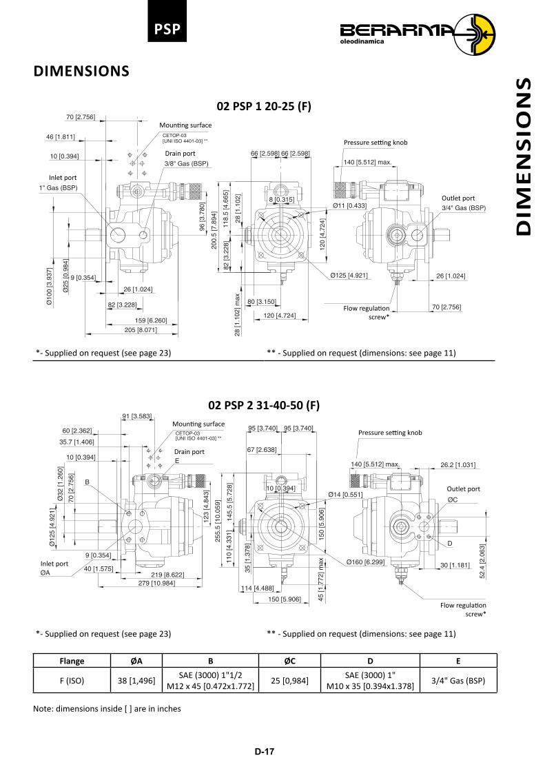
DIMENSIONS
02 PSP 1 20-25 (F)
28 [1
.102
]
82 [3
.228
]
120 [4.724]
80 [3.150]
28 [1
.102
] max
Ø125 [4.921]
120
[4.7
24]
Ø11 [0.433]8 [0.315]
66 [2.598]66 [2.598]
159 [6.260]
205 [8.071]
82 [3.228]
26 [1.024]
Ø10
0 [3
.937
]
Ø25
[0.9
84]
9 [0.354]
70 [2.756]
46 [1.811]
10 [0.394]
26 [1.024]
70 [2.756]
CETOP-03[UNI ISO 4401-03] **
96 [3
.780
]
200.
5 [7
.894
]
118.
5 [4
.665
]
140 [5.512] max.
1" Gas (BSP)
3/4" Gas (BSP)
3/8" Gas (BSP)
Inlet port
Mounting surface
Drain port
Pressure setting knob
Flow regulation screw*
Outlet port
*- Supplied on request (see page 23) ** - Supplied on request (dimensions: see page 11)
02 PSP 2 31-40-50 (F)
CETOP-03[UNI ISO 4401-03] **
30 [1.181]
52.4
[2.0
63]
26.2 [1.031]
110
[4.3
31]
35 [1
.378
]
45 [1
.772
] max
114 [4.488]
150 [5.906]
10 [0.394]
Ø160 [6.299]
150
[5.9
06]
Ø14 [0.551]
95 [3.740]95 [3.740]
219 [8.622]279 [10.984]
40 [1.575]
9 [0.354]
Ø12
5 [4
.921
]
10 [0.394]
70 [2
.756
]
Ø32
[1.2
60]
35.7 [1.406]
60 [2.362]
91 [3.583]
140 [5.512] max.
67 [2.638]
145.
5 [5
.728
]
123
[4.8
43]
255.
5 [1
0.05
9]
ØA
E
B
ØC
D
Inlet port
Mounting surface
Drain port
Pressure setting knob
Flow regulation screw*
Outlet port
*- Supplied on request (see page 23) ** - Supplied on request (dimensions: see page 11)
Flange ØA B ØC D E
F (ISO) 38 [1,496]SAE (3000) 1"1/2
M12 x 45 [0.472x1.772]25 [0,984]
SAE (3000) 1"M10 x 35 [0.394x1.378]
3/4" Gas (BSP)
Note: dimensions inside [ ] are in inches
DIM
EN
SIO
NS
D-18
PSPD
IME
NS
ION
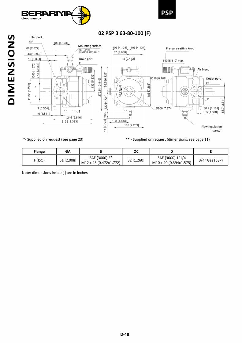
S 02 PSP 3 63-80-100 (F)
CETOP-03[UNI ISO 4401-03] **
35 [1.378]30.2 [1.189]
58.7
[2.3
11]
45 [1
.772
] max
.
123 [4.843]
185 [7.283]
120
[4.7
24]
12 [0.472]
43 1
.693
]
Ø200 [7.874]
Ø18 [0.709]
185
[7.2
83]
105 [4.134]105 [4.134]
10 [0.394]
43 [1.693]
Ø40
[1.5
75]
77.8
[3.0
63]
Ø16
0 [6
.299
]
9 [0.354]
46 [1.811]
313 [12.323]245 [9.646]
105 [4.134]
68 [2.677]
140 [5.512] max.
67 [2.638]
155.
5 [6
.122
]
275.
5 [1
0.84
6]
133
[5.2
36]
ØC
B
ØA
E
D
Inlet port
Mounting surface
Drain port
Pressure setting knob
Flow regulation screw*
Outlet port
Air bleed
*- Supplied on request (see page 23) ** - Supplied on request (dimensions: see page 11)
Flange ØA B ØC D E
F (ISO) 51 [2,008]SAE (3000) 2"
M12 x 45 [0.472x1.772]32 [1,260]
SAE (3000) 1"1/4M10 x 40 [0.394x1.575]
3/4" Gas (BSP)
Note: dimensions inside [ ] are in inches
D-19
PSP
DIM
EN
SIO
NS
E
B
D
AC
Primary pump 02 PVS PSP 1 F
Secondary pump
A B C D E
1P gear pump132
[5.197]64
[2.520]46
[1.811]196
[7.717] please consult
gearpump
catalogue
1M gear pump132
[5.197]64
[2.520]46
[1.811]196
[7.717]
2 gear pump132
[5.197]72
[2.835]46
[1.811]204
[8.031]
C E D
A B
Primary pump 02 PVS PSP 1 F
Secondary pump A B C D E
01-PLP-F205
[8.071]107
[4.213]46
[1.811]201
[7.913]26
[1.024]
01-PLP-FGR2204
[8.031]107
[4.213]46
[1.811]201
[7.913]26
[1.024]
ED
BAC
Primary pump 02 PVS PSP 1 F
Secondary pump A B C D E
02 PVS PSP 126
[1.024]207
[8.150]46
[1.811]207
[8.150]159
[6.260]
Note: dimensions inside [ ] are in inches
D-20
PSPD
IME
NS
ION
S
EB
DA
C
Primary pump 02 PVS PSP 2 F
Secondary pump
A B C D E
1P gear pump173
[6.811]90
[3.543]60
[2.362]263
[10.354]please consult
gearpump
catalogue
1M gear pump173
[6.811]90
[3.543]60
[2.362]263
[10.354]
2 gear pump173
[6.811]90
[3.543]60
[2.362]263
[10.354]
3 gear pump173
[6.811]90
[3.543]60
[2.362]263
[10.354]
D
F
E
C A B
Primary pump 02 PVS PSP 2 F
Secondary pump
A B C D E F
01-PLP 05 F258
[10.157]107
[4.213]60
[2.362]240
[9.449]40
[1.575]30
[1.181]
01-PLP 05 FGR2263
[10.354]107
[4.213]60
[2.362]245
[9.646]40
[1.575]30
[1.181]
D
C
FBAE
Primary pump 02 PVS PSP 2 F
Secondary pump
A B C D E F
02 PVS PSP 1 F40
[1.575]246
[9.685]30
[1.181]159
[6.260]60
[2.362]260
[10.236]
D
FB E
C
AG
Primary pump 02 PVS PSP 2 F
Secondary pump
A B C D E F G
02 PVS PSP 2 F40
[1.575]275
[10.827]30
[1.181]275
[10.827]220
[8.661]275
[10.827]60
[2.362]
Note: dimensions inside [ ] are in inches
D-21
PSP
DIM
EN
SIO
NS
E
B
D
A
C
Primary pump 02 PVS PSP 3 F
Secondary pump
A B C D E
1P gear pump198
[7.795]90
[3.543]68
[2.677]288
[11.339]please consult
gearpump
catalogue
1M gear pump198
[7.795]90
[3.543]68
[2.677]288
[11.339]
2 gear pump198
[7.795]90
[3.543]68
[2.677]288
[11.339]
3 gear pump198
[7.795]90
[3.543]68
[2.677]288
[11.339]
F
E
A
D
C B
Primary pump 02 PVS PSP 3 F
Secondary pump
A B C D E F
01 PLP 05 F283
[11.142]107
[4.213]68
[2.677]259
[10.197]46
[1.811]35
[1.378]
01 PLP 05 FGR2288
[11.339]107
[4.213]68
[2.677]264
[10.394]46
[1.811]35
[1.378]
FE
B
C
D A
Primary pump 02 PVS PSP 3 F
Secondary pump
A B C D E F
02 PVS PSP 1 F46
[1.811]265
[10.433]35
[1.378]68
[2.677]285
[11.220]159
[6.260]
FB
EC
AD
Primary pump 02 PVS PSP 3 F
Secondary pump
A B C D E F
02 PVS PSP 2 F46
[1.811]295
[11.614]35
[1.378]68
[2.677]300
[11.811]220
[8.661]
02 PVS PSP 3 F46
[1.811]315
[12.402]35
[1.378]68
[2.677]315
[12.402]245
[8.661]
Note: dimensions inside [ ] are in inchesFor the dimensions of the other solutions described on page 8, please contact Berarma Technical Service.
D-22
PSP
ACCESSORIES
KEY-LOCK PRESSURE COMPENSATOR DEVICE
99 [3.898]82 [3.228]
166 [6.535]
Note: In the case of combined pumps with Key-Lock pressure compensator, please contact Berarma Technical Service.
PRESSURE RELIEF VALVE FOR PSP PUMP (CODE 2010500600)
CETOP-03[UNI ISO 4401-03]
Ø5.5 [0.217]
46 [1.811]
31 [1
.221
]
10 [0.394]
46 [1
.811
]
16.3
[0.6
42]
26.6
[1.0
47]
32.5
[1.2
80]
65 [2.560]
6 [0
.236
]
19 [0.748]
27.8 [1.095]
40.5 [1.595]
103 [4.055]
Mounting surface
KEY-LOCK PRESSURE RELIEF VALVE FOR PSP PUMP (CODE 2010500700)
[UNI ISO 4401-03]CETOP-03
99 [3.898]
Ø5.5 [0.217]
46 [1.811]
31 [1
.221
]
10 [0.394]
46 [1
.811
]
16.3
[0.6
42]
26.6
[1.0
47]
32.5
[1.2
80]
87 [3.425]
6 [0
.236
]
27.8 [1.095]
40.5 [1.595]
103 [4.055]
19 [0.748]Mounting surface
Note: dimensions inside [ ] are in inches
AC
CE
SS
OR
IES
D-23
PSP
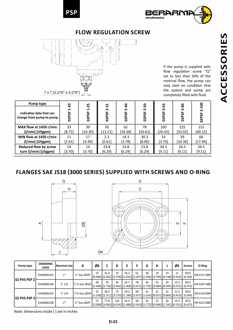
FLOW REGULATION SCREW
7 x 7 [0.276" x 0.276"]
If the pump is supplied with flow regulation screw "Q" set to less than 50% of the nominal flow, the pump can only start on condition that the system and pump are completely filled with fluid.
Pump type
02PS
P 1-
20
02PS
P 1-
25
02PS
P 2-
31
02PS
P 2-
40
02PS
P 2-
50
02PS
P 3-
63
02PS
P 3-
80
02PS
P 3-
100
Indicative data that can change from pump to pump
MAX flow at 1450 r/min (l/min) [USgpm]
33[8.72]
39[10.30]
50[13.21]
62[16.38]
78[20.61]
100[26.42]
125[33.02]
152[40.15]
MIN flow at 1450 r/min (l/min) [USgpm]
11[2.91]
17[4.49]
2.3[0.61]
14.3[3.78]
30.3[8.00]
14[3.70]
39[10.30]
66[17.44]
Reduced flow by screw turn (l/min) [USgpm]
14[3.70]
14[3.70]
23.8[6.29]
23.8[6.29]
23.8[6.29]
34.5[9.11]
34.5[9.11]
34.5[9.11]
FLANGES SAE J518 (3000 SERIES) SUPPLIED WITH SCREWS AND O-RINGD
E FC
G
ØBA
H
ØKJ
Pump typeORDERING
CODENominal size A ØB C D E F G H J ØK Screws O-Ring
02 PVS PSP 25540000102 1" 1" Gas (BSP)
25[0.984]
52.4[2.063]
70[2.756]
26.2[1.031]
52[2.047]
38[1.496]
18[0.709]
19[0.748]
11[0.433]
M10 [0.394]
OR 4131 NBR
5540000106 1" 1/2 1"½ Gas (BSP)38
[1.496]70
[2.756]93
[3.661]35.7
[1.406]78
[3.071]44
[1.732]25
[0.984]24
[0.945]13.5
[0.531]M12
[0.472]OR 4187 NBR
02 PVS PSP 35540000104 1" 1/4 1"¼ Gas (BSP)
32[1.260]
58.7[2.311]
79[3.110]
30.2[1.189]
68[2.677]
41[1.614]
21[0.827]
22[0.866]
11.5[0.453]
M10 [0.394]
OR 4150 NBR
5540000108 2" 2" Gas (BSP)51
[2.008]77.8
[3.063]102
[4.016]42.9
[1.689]90
[3.543]45
[1.772]25
[0.984]30
[1.181]13.5
[0.531]M12
[0.472]OR 4225 NBR
Note: dimensions inside [ ] are in inches
AC
CE
SS
OR
IES
D-24
PSP
INSTRUCTIONS FOR INSTALLATION AND USE
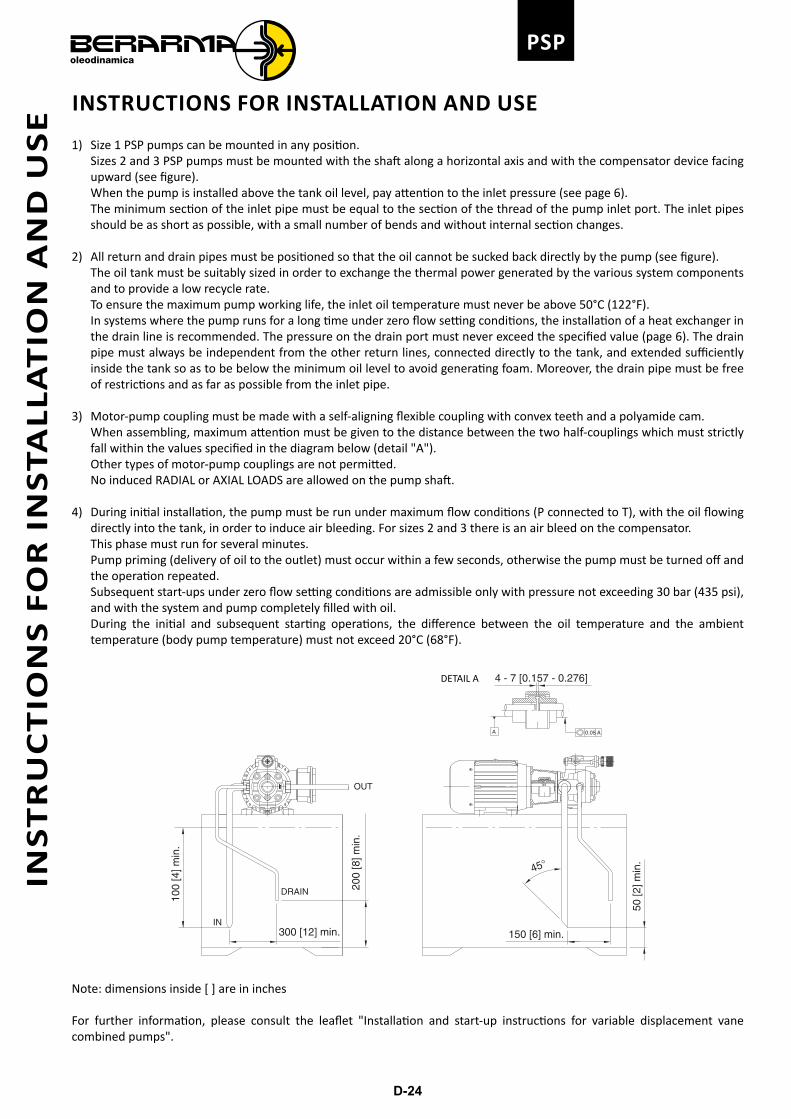
1) Size 1 PSP pumps can be mounted in any position. Sizes 2 and 3 PSP pumps must be mounted with the shaft along a horizontal axis and with the compensator device facing
upward (see figure). When the pump is installed above the tank oil level, pay attention to the inlet pressure (see page 6). The minimum section of the inlet pipe must be equal to the section of the thread of the pump inlet port. The inlet pipes
should be as short as possible, with a small number of bends and without internal section changes.
2) All return and drain pipes must be positioned so that the oil cannot be sucked back directly by the pump (see figure). The oil tank must be suitably sized in order to exchange the thermal power generated by the various system components
and to provide a low recycle rate. To ensure the maximum pump working life, the inlet oil temperature must never be above 50°C (122°F). In systems where the pump runs for a long time under zero flow setting conditions, the installation of a heat exchanger in
the drain line is recommended. The pressure on the drain port must never exceed the specified value (page 6). The drain pipe must always be independent from the other return lines, connected directly to the tank, and extended sufficiently inside the tank so as to be below the minimum oil level to avoid generating foam. Moreover, the drain pipe must be free of restrictions and as far as possible from the inlet pipe.
3) Motor-pump coupling must be made with a self-aligning flexible coupling with convex teeth and a polyamide cam. When assembling, maximum attention must be given to the distance between the two half-couplings which must strictly
fall within the values specified in the diagram below (detail "A"). Other types of motor-pump couplings are not permitted. No induced RADIAL or AXIAL LOADS are allowed on the pump shaft.
4) During initial installation, the pump must be run under maximum flow conditions (P connected to T), with the oil flowing directly into the tank, in order to induce air bleeding. For sizes 2 and 3 there is an air bleed on the compensator.
This phase must run for several minutes. Pump priming (delivery of oil to the outlet) must occur within a few seconds, otherwise the pump must be turned off and
the operation repeated. Subsequent start-ups under zero flow setting conditions are admissible only with pressure not exceeding 30 bar (435 psi),
and with the system and pump completely filled with oil. During the initial and subsequent starting operations, the difference between the oil temperature and the ambient
temperature (body pump temperature) must not exceed 20°C (68°F).
100
[4] m
in.
150 [6] min.
50 [2
] min
.
300 [12] min.
200
[8] m
in.
4 - 7 [0.157 - 0.276]
45°
DRAIN
IN
OUT
0.05 AA
DETAIL A
Note: dimensions inside [ ] are in inches
For further information, please consult the leaflet "Installation and start-up instructions for variable displacement vane combined pumps".
INS
TR
UC
TIO
NS
FO
R I
NS
TAL
LA
TIO
N A
ND
US
E