Embed Size (px)
Citation preview
www.cypress.com Document No. 001-54460 Rev. *G 1
AN54460
PSoC® 3 and PSoC 5LP Interrupts
Author: Vivek Shankar Kannan
Associated Project: Yes
Associated Part Family: All PSoC 3 and PSoC 5LP families
Software Version: PSoC Creator™ 3.0 SP1 and higher
Related Application Notes: AN90799, AN90833, AN60630, AN89610
To get the latest version of this application note, or the associated project file, please visit http://www.cypress.com/go/an54460.
AN54460 explains the interrupt architecture in PSoC® 3 and PSoC 5LP, and its configuration in PSoC Creator™ IDE
with the help of example projects. Advanced interrupt topics such as handling re-entrant functions, interrupt code
optimization, interrupt latency, and debug techniques are also explained.
Contents
Introduction ....................................................................... 1 PSoC Interrupt Architecture .............................................. 2
PSoC Interrupt Features............................................... 2 Interrupt Support in PSoC Creator .................................... 5
Interrupt Component Configuration .............................. 5 Interrupt Priority Configuration ...................................... 7
Interrupt Projects ............................................................... 8 Simple Interrupt Project ................................................ 8 PICU Interrupt Project ................................................ 11 LVD Interrupt Project .................................................. 16 SysTick Interrupt Project ............................................ 20
Advanced Interrupt Topics .............................................. 21 Optimizing Interrupt Code........................................... 21 Interrupt Component APIs .......................................... 21 Interrupts and Other Components .............................. 21 Interrupt Latency ........................................................ 22 Debugging .................................................................. 22 Unsupported Fixed Function Interrupts ...................... 22 Forcing Interrupt Vector Number ................................ 23
Summary ......................................................................... 25 Project Summary ........................................................ 25
Appendix A – Interrupt Sources in PSoC ........................ 26 Appendix B - Re-Entrant Functions in PSoC 3 ................ 28
Re-Entrancy in Keil C51 Compiler .............................. 28 Re-entrancy Support in PSoC Creator ....................... 28 Determining Re-entrant Functions .............................. 30
Worldwide Sales and Design Support ............................. 33
Introduction
Interrupts are an important part of any embedded application. They free the CPU from having to continuously poll for the occurrence of a specific event and, instead, notify the CPU only when that event occurs. In system-on-chip (SoC) architectures such as PSoC, interrupts are frequently used to communicate the status of on-chip peripherals to the CPU.
AN54460 introduces you to the PSoC 3and PSoC 5LP interrupt architectures. It also shows how interrupts are supported in the PSoC Creator IDE, the development tool for these PSoC devices. Advanced interrupt concepts are explained in detail. Several example projects are attached to this application note to demonstrate various interrupt use cases.
This application note assumes that you know at least the basics of how to use the PSoC Creator IDE. If you are new to PSoC Creator, see the PSoC Creator home page. You can also refer to the application notes – AN54181 - Getting Started with PSoC 3 and AN77759 - Getting Started with PSoC 5LP - which introduce the PSoC 3 and PSoC 5LP devices respectively, and the IDE tool using simple projects.
Application notes explaining the interrupt architectures of other PSoC product families are also available. Refer to application notes - AN90799 – PSoC 4 Interrupts and AN90833 – PSoC 1 Interrupts – which are respectively the PSoC 4 and PSoC 1 counterparts of this application note.
PSoC® 3 and PSoC 5LP Interrupts
www.cypress.com Document No. 001-54460 Rev. *G 2
PSoC Interrupt Architecture
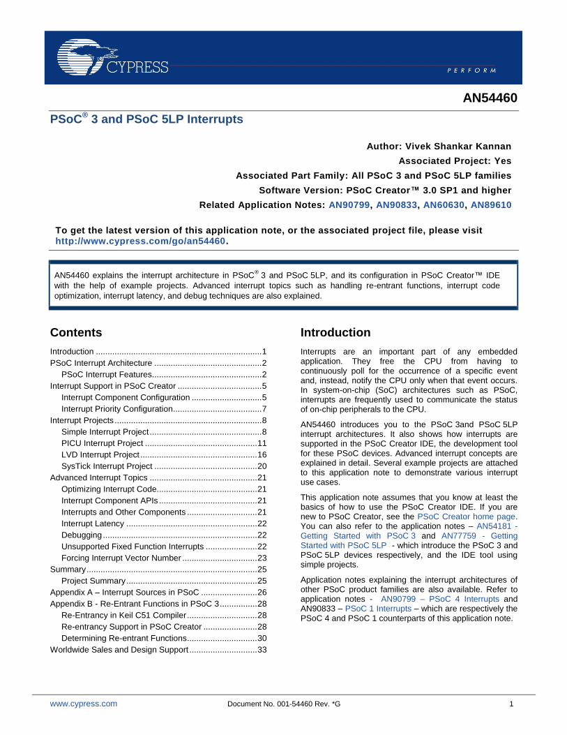
This section gives an overview of the interrupt architectures in PSoC 3 and PSoC 5LP. Figure 1 shows a simplified block diagram:
Figure 1. PSoC 3, PSoC 5LP Interrupt Architecture
Interrupt
Controller
int[0]
int[1]
int[31]
CPU
Interrupt
Lines
There are 32 interrupt lines – int[0] to int[31] – in PSoC 3, PSoC 5LP. Each interrupt line can be assigned one of eight priority levels (0 to 7), where 0 is the highest priority. Each interrupt line is assigned an interrupt vector address, which refers to the starting address of the interrupt code. The CPU branches to this address after receiving an interrupt request. The interrupt code is referred to as the Interrupt Service Routine (ISR).
The interrupt controller acts as the interface between the interrupt lines and the CPU. It sends the interrupt vector address of an interrupt line to the CPU along with the interrupt request signal. The interrupt controller also receives acknowledgement signals from the CPU on interrupt entry and exit conditions. The interrupt controller resolves interrupt priority in the case of requests from multiple interrupt lines.
For more detailed information on the operation of interrupts, refer to the PSoC 3, or PSoC 5LP Technical Reference Manual (TRM).
PSoC Interrupt Features
PSoC 3, and PSoC 5LP provide the following enhanced interrupt features that are not supported by other traditional microcontrollers:
Configurable Interrupt Vector Address: With PSoC you can dynamically configure the interrupt vector address. The
CPU execution can be directly branched to any ISR code when the interrupt occurs. This reduces interrupt execution latency in PSoC compared to traditional microcontrollers.
In traditional microcontrollers, the interrupt vector address is fixed for each interrupt line. Typically, a “JUMP” instruction is placed in that fixed address to branch the CPU execution to the actual ISR code.
Flexible Interrupt Sources: In traditional microcontrollers, the interrupt source is hard-wired to each interrupt line. PSoC
gives you the flexibility to choose the interrupt source for each interrupt line. This flexible architecture enables any digi tal signal to be configured as an interrupt source.
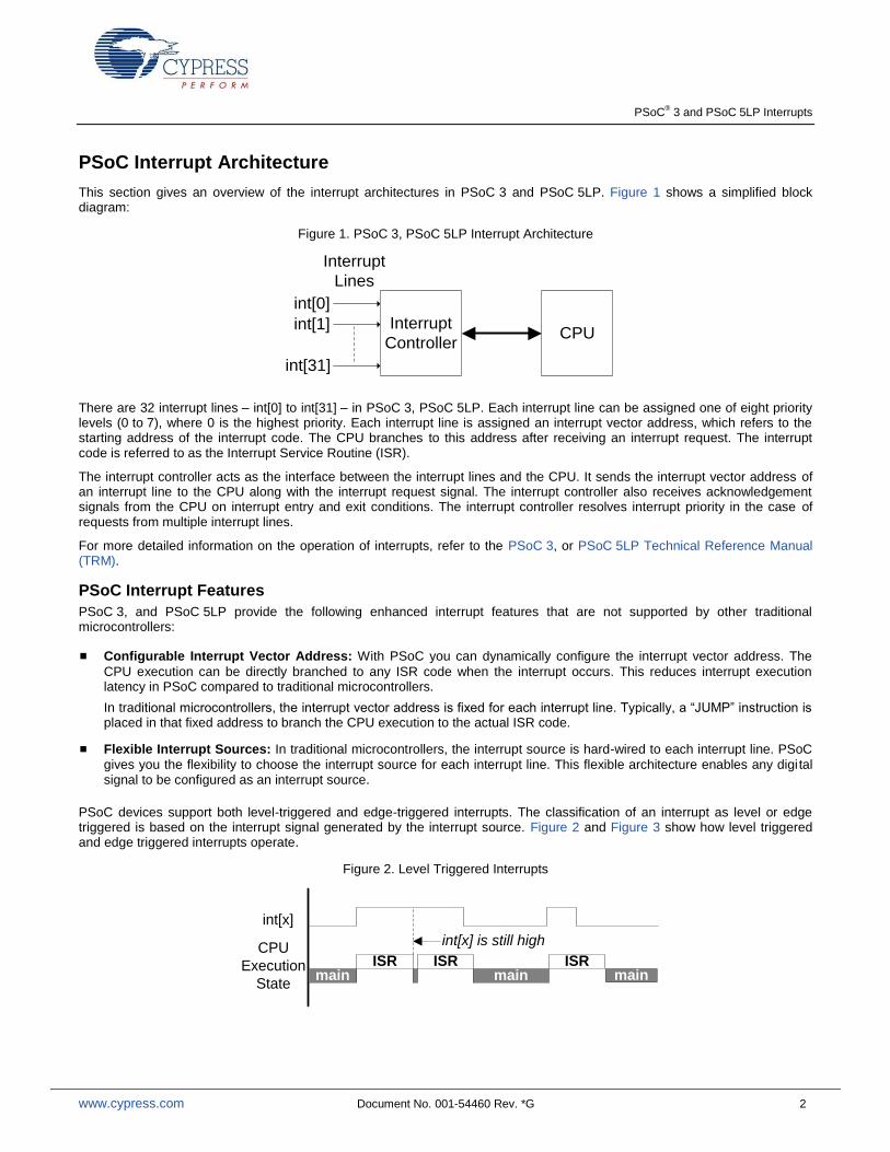
PSoC devices support both level-triggered and edge-triggered interrupts. The classification of an interrupt as level or edge triggered is based on the interrupt signal generated by the interrupt source. Figure 2 and Figure 3 show how level triggered and edge triggered interrupts operate.
Figure 2. Level Triggered Interrupts
int[x]
CPU
Execution
Statemain
ISR ISRmain
ISRmain
int[x] is still high
PSoC® 3 and PSoC 5LP Interrupts
www.cypress.com Document No. 001-54460 Rev. *G 3
Figure 3. Edge Triggered Interrupts
int[x]
CPU
Execution
Statemain
ISRmain
ISRmain
ISR
Assuming that the interrupt line is initially inactive (logic low), the following sequence of events explains how level-triggered and edge-triggered interrupts are handled:
On a rising edge event on the interrupt line, the interrupt controller registers the interrupt request. The interrupt line is now in the pending state, which refers to interrupts whose requests have not yet been serviced by the CPU.
The interrupt controller then sends the interrupt vector address along with the interrupt request signal to the CPU. When the CPU starts executing the ISR of the interrupt line, the pending state of the interrupt line is cleared.
For level-triggered interrupts: If after completing the ISR the interrupt line is still high, the interrupt line becomes pended and the ISR is executed again, as Figure 2 shows. The ISR is continually executed as long as the interrupt line is high.
For edge-triggered interrupts: If while the ISR is being executed one or more rising edges on that interrupt line occur, they are logged as a single pending request. The pending interrupt is serviced again after the current ISR execution is complete, as Figure 3 shows.
Edge-triggered interrupts are pulse signals and so are often called pulse interrupts. The minimum pulse width for an edge triggered interrupt is one bus clock cycle. PSoC has rising edge detect logic to ensure that the interrupt is triggered once on a rising edge. This feature is explained in the next section.
Each of the interrupt lines can be driven by one of three interrupt sources, as Figure 4 shows. Multiplexer logic selects the source for each interrupt line.
Figure 4. Interrupt Sources in PSoC 3 and PSoC 5LP
DMA nrq Interrupt Source
Fixed Function Interrupt Source
Rising
Edge
DetectUDB Interrupt
Source
Digital
System
Interconnect
0
1
2
3
int[n]
IDMUX
n = 0 to 31
Direct Path To Interrupt
Controller
The interrupt sources are described in detail as follows:
Fixed Function Interrupt Sources
These are the predefined set of interrupt sources from the on-chip peripherals. Examples of these include the interrupt signals from the fixed function timers, counters, Port Interrupt Control Unit (PICU), and so on. See Appendix A for the list of interrupt sources in PSoC 3, PSoC 5LP devices .
Most of the fixed function interrupt sources are level interrupts. For these interrupts the peripheral's status register must be read in the ISR, for two reasons:
1. The status register tells what condition generated the interrupt. For example, in the case of a PICU interrupt, each bit of the PICU status register corresponds to a port pin.
PSoC® 3 and PSoC 5LP Interrupts
www.cypress.com Document No. 001-54460 Rev. *G 4
2. Reading the status register clears the status bits, which brings the interrupt line back low. If the status register is not read in the ISR, the ISR is executed continuously.
DMA nrq Interrupt Source
Each direct memory access (DMA) channel in PSoC 3 and PSoC 5LP generates a pulse signal on the completion of a DMA transfer operation. This transfer complete signal (referred to as the nrq signal) can be used to trigger an interrupt after the
DMA data transfer is complete. This is an edge-triggered interrupt.
UDB Interrupt Sources
Any digital signal can be configured as an interrupt source by routing it through the digital system interconnect (DSI). These sources are broadly referred to as UDB interrupt sources because most of these interrupt sources are from the universal digital blocks (UDBs) in PSoC. The UDB is the basic building block for configurable digital peripherals, such as UART, SPI, I2C, timers, counters, and PWMs.
The fixed function interrupt sources can also be routed through the DSI interface, as well as the dedicated routes shown in Figure 4 on page 3.
There are two paths that exist for the UDB interrupt sources.
1. The first path is a direct connection of the UDB interrupt source to the interrupt line - see Direct Path in Figure 4 on page 3. This is used for level triggered UDB interrupts, for example by communication peripherals such as UART and SPI to indicate that a data buffer has data to be read.
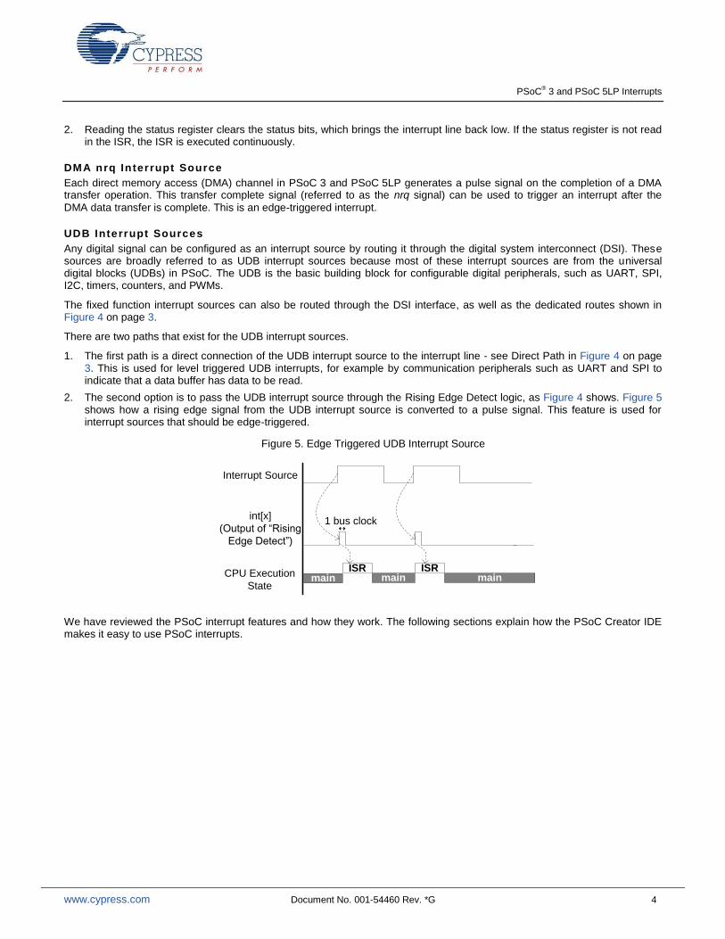
2. The second option is to pass the UDB interrupt source through the Rising Edge Detect logic, as Figure 4 shows. Figure 5 shows how a rising edge signal from the UDB interrupt source is converted to a pulse signal. This feature is used for interrupt sources that should be edge-triggered.
Figure 5. Edge Triggered UDB Interrupt Source
int[x]
(Output of “Rising
Edge Detect”)
CPU Execution
Statemain
ISRmain main
1 bus clock
Interrupt Source
ISR
We have reviewed the PSoC interrupt features and how they work. The following sections explain how the PSoC Creator IDE makes it easy to use PSoC interrupts.
PSoC® 3 and PSoC 5LP Interrupts
www.cypress.com Document No. 001-54460 Rev. *G 5
Interrupt Support in PSoC Creator
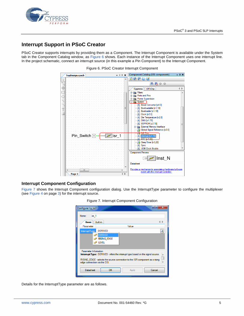
PSoC Creator supports interrupts by providing them as a Component. The Interrupt Component is available under the System tab in the Component Catalog window, as Figure 6 shows. Each instance of the Interrupt Component uses one interrupt line. In the project schematic, connect an interrupt source (in this example a Pin Component) to the Interrupt Component.
Figure 6. PSoC Creator Interrupt Component
Interrupt Component Configuration
Figure 7 shows the Interrupt Component configuration dialog. Use the InterruptType parameter to configure the multiplexer (see Figure 4 on page 3) for the interrupt source.
Figure 7. Interrupt Component Configuration
Details for the InterruptType parameter are as follows.
PSoC® 3 and PSoC 5LP Interrupts
www.cypress.com Document No. 001-54460 Rev. *G 6
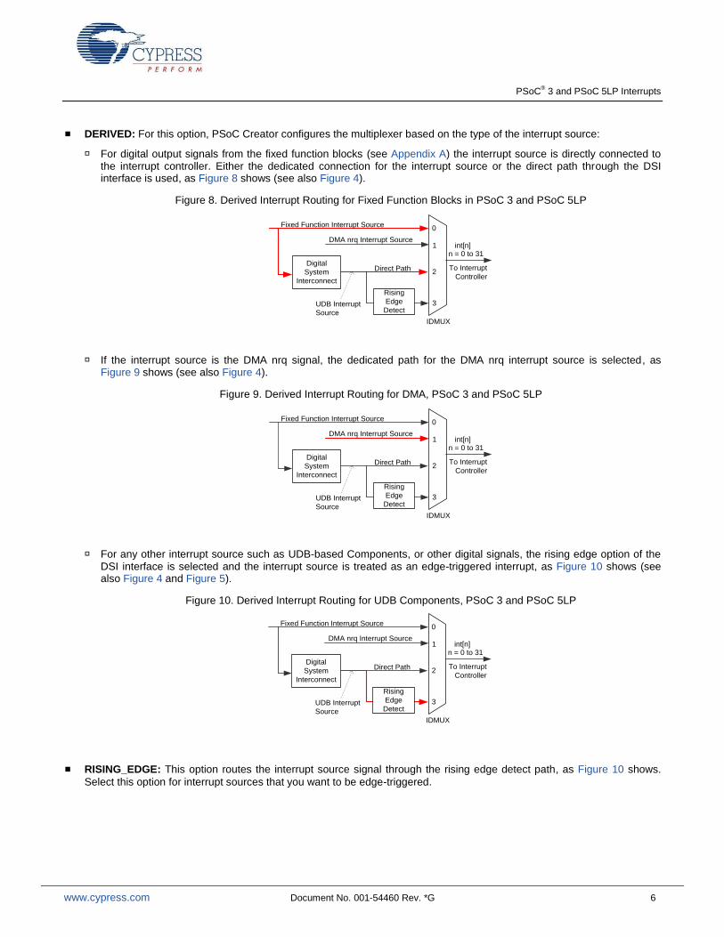
DERIVED: For this option, PSoC Creator configures the multiplexer based on the type of the interrupt source:
For digital output signals from the fixed function blocks (see Appendix A) the interrupt source is directly connected to the interrupt controller. Either the dedicated connection for the interrupt source or the direct path through the DSI interface is used, as Figure 8 shows (see also Figure 4).
Figure 8. Derived Interrupt Routing for Fixed Function Blocks in PSoC 3 and PSoC 5LP
DMA nrq Interrupt Source
Fixed Function Interrupt Source
Rising
Edge
DetectUDB Interrupt
Source
Digital
System
Interconnect
0
1
2
3
int[n]
IDMUX
n = 0 to 31
Direct Path To Interrupt
Controller
If the interrupt source is the DMA nrq signal, the dedicated path for the DMA nrq interrupt source is selected, as Figure 9 shows (see also Figure 4).
Figure 9. Derived Interrupt Routing for DMA, PSoC 3 and PSoC 5LP
DMA nrq Interrupt Source
Fixed Function Interrupt Source
Rising
Edge
DetectUDB Interrupt
Source
Digital
System
Interconnect
0
1
2
3
int[n]
IDMUX
n = 0 to 31
Direct Path To Interrupt
Controller
For any other interrupt source such as UDB-based Components, or other digital signals, the rising edge option of the DSI interface is selected and the interrupt source is treated as an edge-triggered interrupt, as Figure 10 shows (see also Figure 4 and Figure 5).
Figure 10. Derived Interrupt Routing for UDB Components, PSoC 3 and PSoC 5LP
DMA nrq Interrupt Source
Fixed Function Interrupt Source
Rising
Edge
DetectUDB Interrupt
Source
Digital
System
Interconnect
0
1
2
3
int[n]
IDMUX
n = 0 to 31
Direct Path To Interrupt
Controller
RISING_EDGE: This option routes the interrupt source signal through the rising edge detect path, as Figure 10 shows.
Select this option for interrupt sources that you want to be edge-triggered.
PSoC® 3 and PSoC 5LP Interrupts
www.cypress.com Document No. 001-54460 Rev. *G 7
LEVEL: This option routes the interrupt source through the direct path in the DSI interface, as Figure 8 on page 6 shows.
Select this option for interrupt sources that you want to be level-triggered, for example UDB-based Components such as UART, SPI, timer, counter, and PWM.
Note Select only the LEVEL option for interrupts generated by UDB-based components such as UART and SPI. The reason is that these components generate a level interrupt to indicate the UDB FIFO buffer status signal. The FIFO buffer, which is 4 bytes deep, is used to temporarily store data to be transmitted (Tx FIFO) or received (Rx FIFO).
For an Rx FIFO, the FIFO status signal is high as long as there is at least one byte of data to be read by the CPU. If the DERIVED or RISING_EDGE option is selected, the interrupt is triggered only once even if more than one byte is in the buffer. If the ISR is written such that only one byte is read each time the interrupt occurs, additional data in the buffer may be lost.
Interrupt Priority Configuration
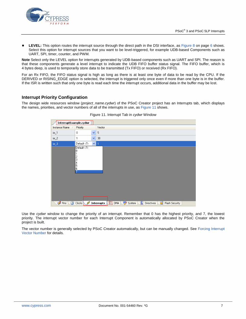
The design wide resources window (project_name.cydwr) of the PSoC Creator project has an Interrupts tab, which displays the names, priorities, and vector numbers of all of the interrupts in use, as Figure 11 shows.
Figure 11. Interrupt Tab in cydwr Window
Use the cydwr window to change the priority of an interrupt. Remember that 0 has the highest priority, and 7, the lowest
priority. The interrupt vector number for each Interrupt Component is automatically allocated by PSoC Creator when the project is built.
The vector number is generally selected by PSoC Creator automatically, but can be manually changed. See Forcing Interrupt Vector Number for details.
PSoC® 3 and PSoC 5LP Interrupts
www.cypress.com Document No. 001-54460 Rev. *G 8
Interrupt Projects
Four PSoC Creator projects are provided as part of this application note that demonstrate basic interrupt, Port Interrupt Control Unit (PICU), Low Voltage Detect (LVD), and SysTick interrupts in PSoC 3 and PSoC 5LP. Note that SysTick is a feature of the Cortex-M3 CPU and is not available in PSoC 3.
Simple Interrupt Project
This section guides you through a step by step procedure to create a simple interrupt-based PSoC Creator project. A completed version of this project, named A_InterruptExample, is attached to this application note.
The objective of this project is to generate a periodic interrupt to toggle a pin (and thus blink an LED) at a desired frequency. The frequency is determined by a Clock Component and a Timer Component. Figure 12 shows the project schematic (developed for the Cypress development kit CY8CKIT-001). The project can be easily adapted to other kits as explained in the Knowledge Base Article - Migrating project from CY8CKIT-001 to CY8CKIT-030 or CY8CKIT-050.
Figure 12. Schematic for Project A_InterruptExample
The Timer Component is a down counter, and the terminal count refers to the condition when the timer has reached its minimum value (zero). On the terminal count, the timer is reloaded with the period value and counting continues. An interrupt can be generated every time the terminal count condition occurs.
The interrupt output from the Timer Component is connected to an Interrupt Component. The digital output pin LED1 is toggled by the ISR code each time the Timer terminal count event occurs.
The interrupt frequency is controlled by the timer_clock frequency and the Timer Period; configure the Timer Component as Figure 13 shows. For a 1-KHz timer_clock frequency and a period of 1000, the terminal count condition is reached once a second. Check the “Interrupt on TC” box, and make sure that the Implementation is UDB. Leave all other parameters at their default settings.
Figure 13. Timer Component Configuration
PSoC® 3 and PSoC 5LP Interrupts
www.cypress.com Document No. 001-54460 Rev. *G 9
The Timer Component datasheet states that the interrupt output remains asserted until the Timer status register is read. This implies that the interrupt is level-triggered. Configure the Interrupt Component such that the InterruptType is LEVEL, as Figure 7 on page 5 shows.
You can leave the priority of the Interrupt Component at its default value (see Figure 11 on page 7) because there is only one interrupt in this project.
Writ ing the Interrupt Service Rou tine
After the schematic is complete, go to the PSoC Creator menu Build > Generate Application. PSoC Creator generates the source files and header files for the Components used in the project. This includes a default interrupt service routine (ISR) for
each Interrupt Component, in a corresponding source file. This ISR function has the name CY_ISR(isr_name). You must
write the ISR code in the placeholder inside the function, as well as add any relevant #include statements.
In this project, the ISR code does two tasks:
Read the Timer status register to clear the interrupt source. The Timer Component header file must be included in the ISR source file.
Toggle the Pin Component to make the LED blink. The Pin Component header file must be included in the ISR source file.
PSoC Creator provides a region in the beginning of the Interrupt source file for including the header files, as Code 1 shows:
Code 1. Header Code in the ISR Source File
/*********************************************
* Place your includes, defines and code here
*********************************************/
/* `#START isr_1_intc` */
/* Timer component header file */
#include “Timer_1.h”
/* LED1 pin component header file */
#include “LED1.h”
/* `#END` */
The header code should be written only between the #START and #END lines. PSoC Creator preserves only the code written
between these two lines during the build process. Any code that is written outside of these lines is deleted whenever the project is rebuilt.
Code 2 shows the ISR code for this project. It is written in the placeholder region provided inside the ISR function.
Code 2. ISR Code in the ISR Source File
CY_ISR(isr_1_Interrupt)
{
/* Place your Interrupt code here */
/* `#START isr_1_Interrupt` */
/* Read Timer status register to bring the interrupt line low */
Timer_1_ReadStatusRegister();
/* Toggle the LED */
LED1_Write(~LED1_Read());
/* `#END` */
}
The ISR code should be written only between the #START and #END lines. PSoC Creator preserves only the code written
between these two lines during the build process. Any code that is written outside of these lines is deleted whenever the project is rebuilt.
PSoC® 3 and PSoC 5LP Interrupts
www.cypress.com Document No. 001-54460 Rev. *G 10
Complet ing the Main Code
In the main code, the Components are initialized and started, as Code 3 shows:
Code 3. Simple Interrupt Project main.c
void main()
{
/* Place your initialization/startup code here (e.g. MyInst_Start()) */
/* Initialize the interrupt and timer*/
isr_1_Start();
Timer_1_Start();
CyGlobalIntEnable; /* Uncomment this line to enable Global interrupts. */
for(;;)
{
/* Place your application code here. */
/* Do nothing in the main loop; code to do something is in the ISR. */
}
}
In Code 3, the macro CYGlobalIntEnable configures the interrupt controller to generate the interrupt request signal to the
CPU, and also configures the CPU to accept the request signals. This macro is defined in the auto-generated file CyLib.h, and
it takes the appropriate definition based on the PSoC 3or PSoC 5LP device family selected. Use this macro to ensure code portability across multiple compiler tool chains and device families.
The isr_1_Start() function initializes and enables the isr_1 interrupt component. Specifically, it does the following:
Sets the interrupt vector address to the address of the default ISR function provided in the interrupt component source file
Configures the interrupt priority according to the priority value assigned in the cydwr window
Enables the interrupt
Signif icance of Keyword CY_ISR
The interrupt source file defines the ISR function using the CY_ISR macro. Every compiler requires a specific function
definition format to recognize a function as an ISR. The macro, defined in the auto-generated cytypes.h file, provides an ISR definition format that is independent of the compiler.
Similarly, the macro CY_ISR_PROTO declares an ISR function prototype. The declaration is in the header file of the interrupt
component. For example, the interrupt component isr_1 has the following function prototype declaration in the header file isr_1.h:
CY_ISR_PROTO(isr_1_Interrupt);
This macro is also defined in cytypes.h, and takes the appropriate definition depending on the compiler selected.
This completes the simple interrupt based project. The same sequence of steps should be followed for any other interrupt based project. The following sections discuss some of the advanced features available for interrupts in PSoC Creator.
PSoC® 3 and PSoC 5LP Interrupts
www.cypress.com Document No. 001-54460 Rev. *G 11
PICU Interrupt Project
This is the second example project; it is attached to this application note as project B_PICU. It explains the following topics:
1. Use of Port Interrupt Control Unit (PICU), the interrupt associated with the digital input pins
2. How to make a user defined function as an ISR instead of using the default ISR generated by PSoC Creator
This project toggles a pin (and an LED) whenever a switch is pressed, but NOT when it is released. To implement this feature correctly, a switch debounce function is included. Two switches are monitored and debounced, and each switch has a separate LED associated with it. There are many ways to implement these requirements; this project uses an interrupt based implementation.
This project deals just with the interrupt-specific use of the GPIO pins in PSoC. To understand the GPIO configuration features in detail with example projects, refer to the application note AN72382 – Using PSoC 3 and PSoC 5LP GPIO Pins.
This project was developed for the Cypress development kit CY8CKIT-001, but can be easily adapted to other kits as explained in the Knowledge Base Article - Migrating project from CY8CKIT-001 to CY8CKIT-030 or CY8CKIT-050.
PICU Interrupt
For detecting the switch press, use the Port Interrupt Control Unit (PICU) interrupt. There is one PICU interrupt for each port, where each port consists of eight I/O pins. Each one of the eight I/O pins can be individually configured to generate a PICU interrupt, either on a falling edge, or a rising edge, or both edges.
When the configured event occurs on that pin, the corresponding bit of the 8-bit PICU status register is set. The PICU interrupt is the logical OR output of the status register bits. The PICU status register can be read to determine which port pin generated the interrupt.
Project Schematic
The project schematic is shown in Figure 14. Switches SW1 and SW2 on the development kit are connected to two input pins, which are represented as a single Digital Input Pin Component named “Switches”. The PICU interrupt signal from each of the input pins is connected to the Interrupt Component “isr_1”. A second Interrupt Component, “isr_2”, is connected to a Clock Component and a TFF Component to generate a 1 kHz tick interrupt, which is used for switch debouncing.
Figure 14. Schematic for Project B_PICU
PSoC® 3 and PSoC 5LP Interrupts
www.cypress.com Document No. 001-54460 Rev. *G 12
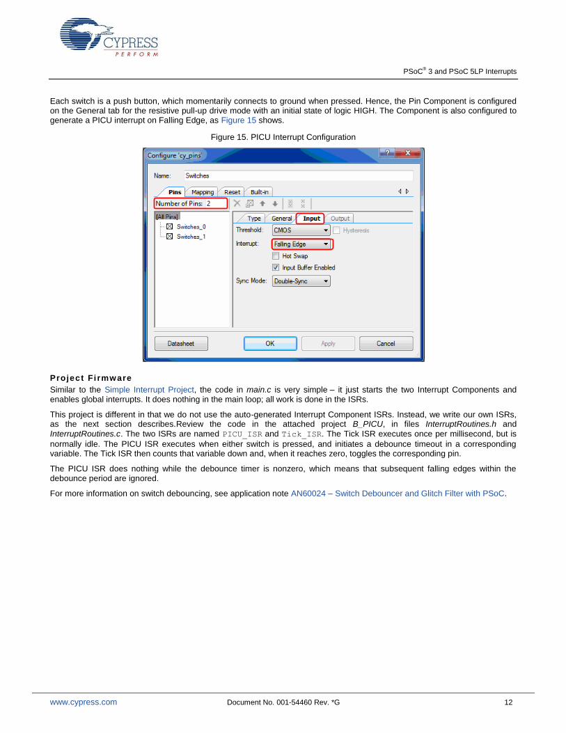
Each switch is a push button, which momentarily connects to ground when pressed. Hence, the Pin Component is configured on the General tab for the resistive pull-up drive mode with an initial state of logic HIGH. The Component is also configured to generate a PICU interrupt on Falling Edge, as Figure 15 shows.
Figure 15. PICU Interrupt Configuration
Project Fi rmware
Similar to the Simple Interrupt Project, the code in main.c is very simple – it just starts the two Interrupt Components and enables global interrupts. It does nothing in the main loop; all work is done in the ISRs.
This project is different in that we do not use the auto-generated Interrupt Component ISRs. Instead, we write our own ISRs, as the next section describes.Review the code in the attached project B_PICU, in files InterruptRoutines.h and
InterruptRoutines.c. The two ISRs are named PICU_ISR and Tick_ISR. The Tick ISR executes once per millisecond, but is
normally idle. The PICU ISR executes when either switch is pressed, and initiates a debounce timeout in a corresponding variable. The Tick ISR then counts that variable down and, when it reaches zero, toggles the corresponding pin.
The PICU ISR does nothing while the debounce timer is nonzero, which means that subsequent falling edges within the debounce period are ignored.
For more information on switch debouncing, see application note AN60024 – Switch Debouncer and Glitch Filter with PSoC.
PSoC® 3 and PSoC 5LP Interrupts
www.cypress.com Document No. 001-54460 Rev. *G 13
Write Your Own ISR
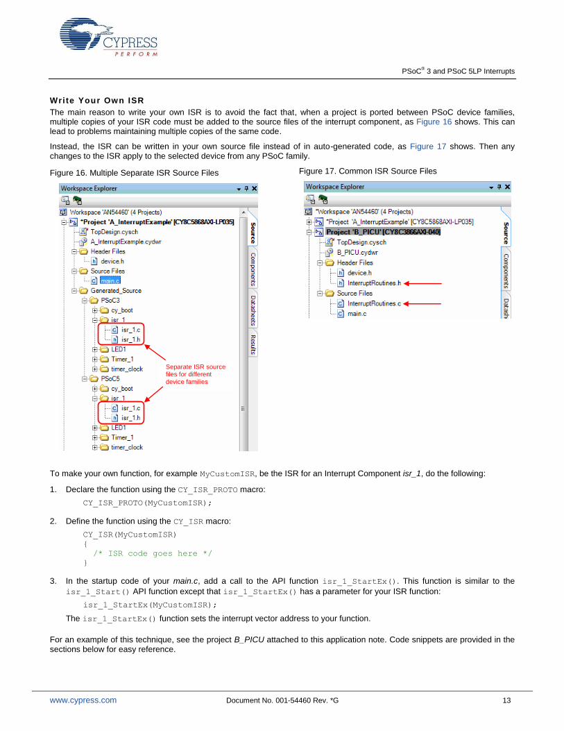
The main reason to write your own ISR is to avoid the fact that, when a project is ported between PSoC device families, multiple copies of your ISR code must be added to the source files of the interrupt component, as Figure 16 shows. This can lead to problems maintaining multiple copies of the same code.
Instead, the ISR can be written in your own source file instead of in auto-generated code, as Figure 17 shows. Then any changes to the ISR apply to the selected device from any PSoC family.
Figure 16. Multiple Separate ISR Source Files
Figure 17. Common ISR Source Files
To make your own function, for example MyCustomISR, be the ISR for an Interrupt Component isr_1, do the following:
1. Declare the function using the CY_ISR_PROTO macro:
CY_ISR_PROTO(MyCustomISR);
2. Define the function using the CY_ISR macro:
CY_ISR(MyCustomISR)
{
/* ISR code goes here */
}
3. In the startup code of your main.c, add a call to the API function isr_1_StartEx(). This function is similar to the
isr_1_Start() API function except that isr_1_StartEx() has a parameter for your ISR function:
isr_1_StartEx(MyCustomISR);
The isr_1_StartEx() function sets the interrupt vector address to your function.
For an example of this technique, see the project B_PICU attached to this application note. Code snippets are provided in the sections below for easy reference.
Separate ISR source files for different device families
PSoC® 3 and PSoC 5LP Interrupts
www.cypress.com Document No. 001-54460 Rev. *G 14
The main() function for the project is given below:
PICU_ISR for the project is shown below:
#include <device.h>
/* Header file containing the custom ISR prototypes */
#include "InterruptRoutines.h"
void main()
{
/* Initialize the two custom defined ISRs */
isr_1_StartEx(PICU_ISR);
isr_2_StartEx(Tick_ISR);
CyGlobalIntEnable; /* Enable global interrupts. */
for(;;)
{
/* Do nothing in the main loop; code to do something
is in the ISRs */
}
}
CY_ISR(PICU_ISR)
{
/* copies of PICU registers */
uint8 CYDATA temp_stat;
/* read the PICU interrupt status register, with a clear on read */
temp_stat = Switches_ClearInterrupt();
/* Process the PICU event on SW1 only if any
ongoing debounce period has timed out */
if(((temp_stat & SW1_MASK) != 0) && (switch_1_timeout == TIMED_OUT))
{
/* reset the debounce timer for this button */
switch_1_timeout = DEBOUNCE_TIME;
}
/* Process the PICU event on SW2 only if any
ongoing debounce period has timed out */
if(((temp_stat & SW2_MASK) != 0) && (switch_2_timeout == TIMED_OUT))
{
/* reset the debounce timer for this button */
switch_2_timeout = DEBOUNCE_TIME;
}
}
PSoC® 3 and PSoC 5LP Interrupts
www.cypress.com Document No. 001-54460 Rev. *G 15
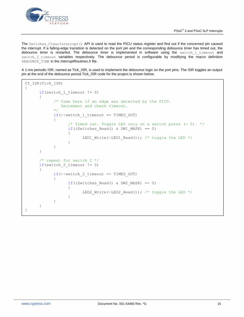
The Switches_ClearInterrupt() API is used to read the PICU status register and find out if the concerned pin caused
the interrupt. If a falling-edge transition is detected on the port pin and the corresponding debounce timer has timed out, the debounce timer is restarted. The debounce timer is implemented in software using the switch_1_timeout and
switch_2_timeout variables respectively. The debounce period is configurable by modifying the macro definition
DEBOUNCE_TIME in the InterruptRoutines.h file.
A 1-ms periodic ISR, named as Tick_ISR, is used to implement the debounce logic on the port pins. The ISR toggles an output pin at the end of the debounce period.Tick_ISR code for the project is shown below.
CY_ISR(Tick_ISR)
{
if(switch_1_timeout != 0)
{
/* Come here if an edge was detected by the PICU.
Decrement and check timeout.
*/
if(--switch_1_timeout == TIMED_OUT)
{
/* Timed out. Toggle LED only on a switch press (= 0). */
if((Switches_Read() & SW1_MASK) == 0)
{
LED1_Write(~LED1_Read()); /* toggle the LED */
}
}
}
/* repeat for switch 2 */
if(switch_2_timeout != 0)
{
if(--switch_2_timeout == TIMED_OUT)
{
if((Switches_Read() & SW2_MASK) == 0)
{
LED2_Write(~LED2_Read()); /* toggle the LED */
}
}
}
}
PSoC® 3 and PSoC 5LP Interrupts
www.cypress.com Document No. 001-54460 Rev. *G 16
LVD Interrupt Project
This is the third example project; it is attached to this application note as project C_LVD. It explains the following topics:
1. Use of the Global Signal Reference Component for generating interrupts
2. Using a semaphore, or flag, variable to communicate between the main code and the ISR
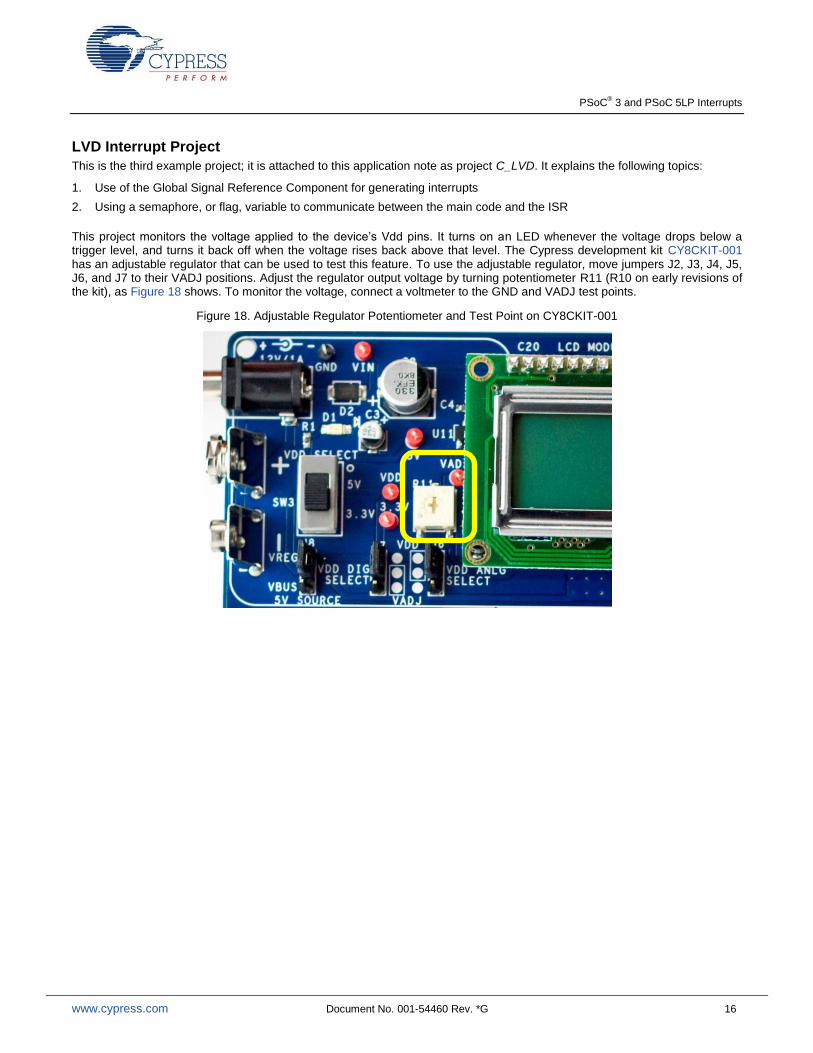
This project monitors the voltage applied to the device’s Vdd pins. It turns on an LED whenever the voltage drops below a trigger level, and turns it back off when the voltage rises back above that level. The Cypress development kit CY8CKIT-001 has an adjustable regulator that can be used to test this feature. To use the adjustable regulator, move jumpers J2, J3, J4, J5, J6, and J7 to their VADJ positions. Adjust the regulator output voltage by turning potentiometer R11 (R10 on early revisions of the kit), as Figure 18 shows. To monitor the voltage, connect a voltmeter to the GND and VADJ test points.
Figure 18. Adjustable Regulator Potentiometer and Test Point on CY8CKIT-001
PSoC® 3 and PSoC 5LP Interrupts
www.cypress.com Document No. 001-54460 Rev. *G 17
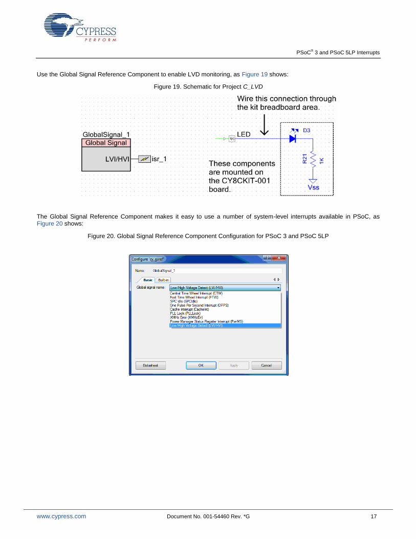
Use the Global Signal Reference Component to enable LVD monitoring, as Figure 19 shows:
Figure 19. Schematic for Project C_LVD
The Global Signal Reference Component makes it easy to use a number of system-level interrupts available in PSoC, as Figure 20 shows:
Figure 20. Global Signal Reference Component Configuration for PSoC 3 and PSoC 5LP
PSoC® 3 and PSoC 5LP Interrupts
www.cypress.com Document No. 001-54460 Rev. *G 18
The project also demonstrates the use of a semaphore, or flag, variable to communicate between the ISR and the main code. This is a common practice in embedded systems design – it transfers tasks from the ISR to the main code thus reducing CPU time spent in an ISR. The variable is defined as a global, of static type if the main and ISR are in the same file
1:
static volatile CYBIT isr_flag = 0; /* semaphore between ISR and main() */
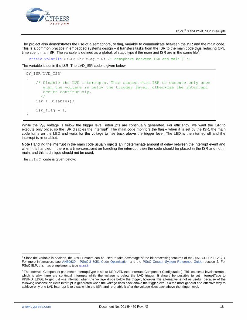
The variable is set in the ISR. The LVD_ISR code is given below.
While the VDD voltage is below the trigger level, interrupts are continually generated. For efficiency, we want the ISR to execute only once, so the ISR disables the interrupt
2. The main code monitors the flag – when it is set by the ISR, the main
code turns on the LED and waits for the voltage to rise back above the trigger level. The LED is then turned off and the interrupt is re-enabled.
Note Handling the interrupt in the main code usually injects an indeterminate amount of delay between the interrupt event and when it is handled. If there is a time-constraint on handling the interrupt, then the code should be placed in the ISR and not in main, and this technique should not be used.
The main() code is given below:
1 Since the variable is boolean, the CYBIT macro can be used to take advantage of the bit processing features of the 8051 CPU in PSoC 3.
For more information, see AN60630 – PSoC 3 8051 Code Optimization and the PSoC Creator System Reference Guide, section 2. For
PSoC 5LP, this macro implements type uint8.
2 The Interrupt Component parameter InterruptType is set to DERIVED (see Interrupt Component Configuration). This causes a level interrupt,
which is why there are continual interrupts while the voltage is below the LVD trigger. It should be possible to set InterruptType to RISING_EDGE to get just one interrupt when the voltage drops below the trigger, however this alternative is not as useful, because of the following reasons: an extra interrupt is generated when the voltage rises back above the trigger level. So the most general and effective way to achieve only one LVD interrupt is to disable it in the ISR, and re-enable it after the voltage rises back above the trigger level.
CY_ISR(LVD_ISR)
{
/* Disable the LVD interrupts. This causes this ISR to execute only once
when the voltage is below the trigger level, otherwise the interrupt
occurs continuously.
*/
isr_1_Disable();
isr_flag = 1;
}
PSoC® 3 and PSoC 5LP Interrupts
www.cypress.com Document No. 001-54460 Rev. *G 19
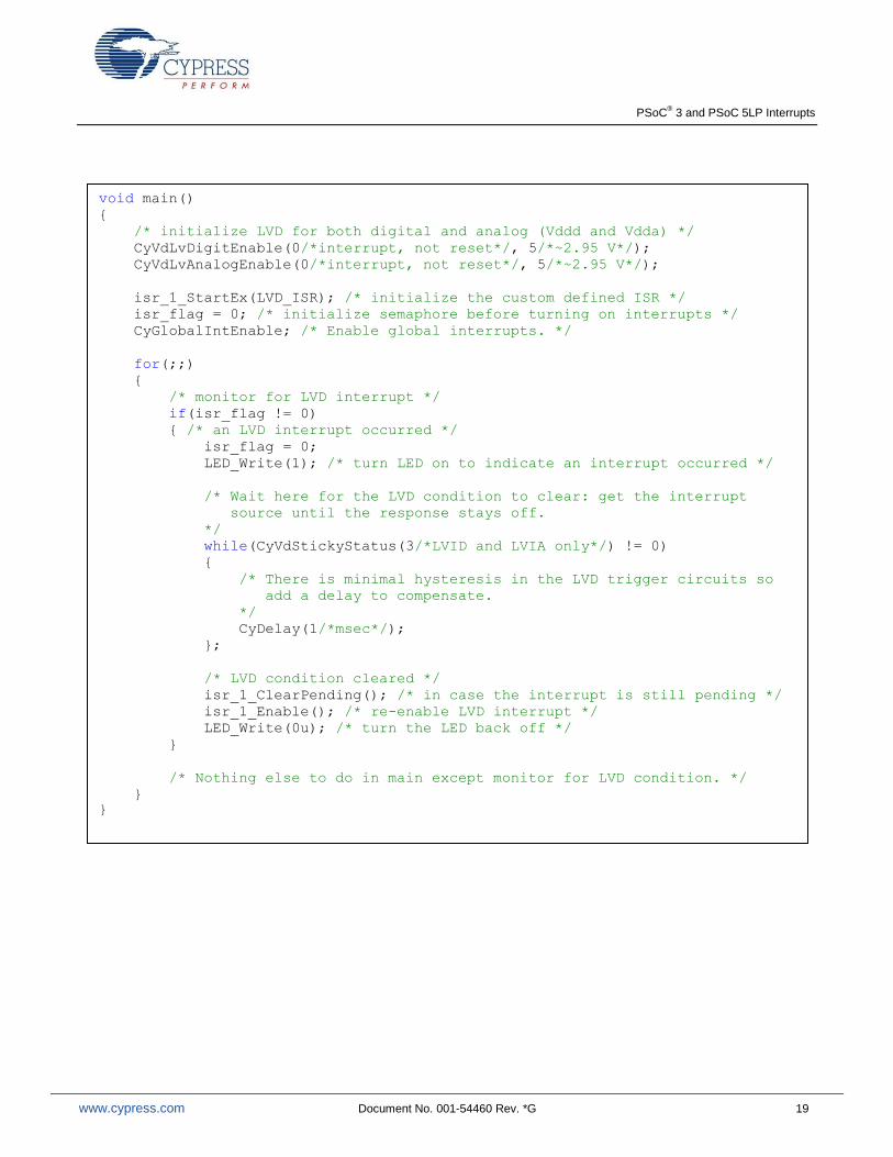
void main()
{
/* initialize LVD for both digital and analog (Vddd and Vdda) */
CyVdLvDigitEnable(0/*interrupt, not reset*/, 5/*~2.95 V*/);
CyVdLvAnalogEnable(0/*interrupt, not reset*/, 5/*~2.95 V*/);
isr_1_StartEx(LVD_ISR); /* initialize the custom defined ISR */
isr_flag = 0; /* initialize semaphore before turning on interrupts */
CyGlobalIntEnable; /* Enable global interrupts. */
for(;;)
{
/* monitor for LVD interrupt */
if(isr_flag != 0)
{ /* an LVD interrupt occurred */
isr_flag = 0;
LED_Write(1); /* turn LED on to indicate an interrupt occurred */
/* Wait here for the LVD condition to clear: get the interrupt
source until the response stays off.
*/
while(CyVdStickyStatus(3/*LVID and LVIA only*/) != 0)
{
/* There is minimal hysteresis in the LVD trigger circuits so
add a delay to compensate.
*/
CyDelay(1/*msec*/);
};
/* LVD condition cleared */
isr_1_ClearPending(); /* in case the interrupt is still pending */
isr_1_Enable(); /* re-enable LVD interrupt */
LED_Write(0u); /* turn the LED back off */
}
/* Nothing else to do in main except monitor for LVD condition. */
}
}
PSoC® 3 and PSoC 5LP Interrupts
www.cypress.com Document No. 001-54460 Rev. *G 20
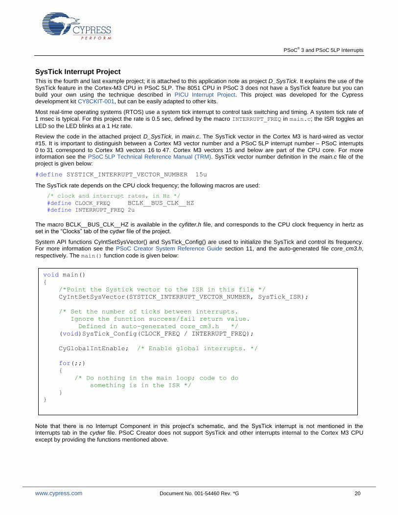
SysTick Interrupt Project
This is the fourth and last example project; it is attached to this application note as project D_SysTick. It explains the use of the SysTick feature in the Cortex-M3 CPU in PSoC 5LP. The 8051 CPU in PSoC 3 does not have a SysTick feature but you can build your own using the technique described in PICU Interrupt Project. This project was developed for the Cypress development kit CY8CKIT-001, but can be easily adapted to other kits.
Most real-time operating systems (RTOS) use a system tick interrupt to control task switching and timing. A system tick rate of 1 msec is typical. For this project the rate is 0.5 sec, defined by the macro INTERRUPT_FREQ in main.c; the ISR toggles an
LED so the LED blinks at a 1 Hz rate.
Review the code in the attached project D_SysTick, in main.c. The SysTick vector in the Cortex M3 is hard-wired as vector
#15. It is important to distinguish between a Cortex M3 vector number and a PSoC 5LP interrupt number – PSoC interrupts 0 to 31 correspond to Cortex M3 vectors 16 to 47. Cortex M3 vectors 15 and below are part of the CPU core. For more information see the PSoC 5LP Technical Reference Manual (TRM). SysTick vector number definition in the main.c file of the project is given below:
#define SYSTICK_INTERRUPT_VECTOR_NUMBER 15u
The SysTick rate depends on the CPU clock frequency; the following macros are used:
/* clock and interrupt rates, in Hz */
#define CLOCK_FREQ BCLK__BUS_CLK__HZ
#define INTERRUPT_FREQ 2u
The macro BCLK__BUS_CLK__HZ is available in the cyfitter.h file, and corresponds to the CPU clock frequency in hertz as set in the “Clocks” tab of the cydwr file of the project.
System API functions CyIntSetSysVector() and SysTick_Config() are used to initialize the SysTick and control its frequency. For more information see the PSoC Creator System Reference Guide section 11, and the auto-generated file core_cm3.h,
respectively. The main() function code is given below:
Note that there is no Interrupt Component in this project’s schematic, and the SysTick interrupt is not mentioned in the Interrupts tab in the cydwr file. PSoC Creator does not support SysTick and other interrupts internal to the Cortex M3 CPU
except by providing the functions mentioned above.
void main()
{
/*Point the Systick vector to the ISR in this file */
CyIntSetSysVector(SYSTICK_INTERRUPT_VECTOR_NUMBER, SysTick_ISR);
/* Set the number of ticks between interrupts.
Ignore the function success/fail return value.
Defined in auto-generated core_cm3.h */
(void)SysTick_Config(CLOCK_FREQ / INTERRUPT_FREQ);
CyGlobalIntEnable; /* Enable global interrupts. */
for(;;)
{
/* Do nothing in the main loop; code to do
something is in the ISR */
}
}
PSoC® 3 and PSoC 5LP Interrupts
www.cypress.com Document No. 001-54460 Rev. *G 21
Advanced Interrupt Topics
Optimizing Interrupt Code
One of the important performance requirements in interrupt based applications is ISR code execution time. In some applications, critical code in the ISR must be executed within a particular time of receiving the interrupt request. Also, interrupt execution should not take too much time and stall the main code execution or other interrupts. To meet these requirements, use the following guidelines:
Avoid function calls in the ISR. Function calls increase the ISR code execution time due to the stack push/pop
overhead involved in calling and returning from functions. Functions may take an indeterminate and overly long time to execute, for example the Character LCD display routines. There is also the case of increased latency in servicing lower-priority interrupts when such function calls are done in a higher-priority ISR.
The recommended technique is to move non-critical function calls to the main code and just set a flag variable in the ISR, as LVD Interrupt Project describes. The main code periodically checks the flag and if set, clears it and calls the function.
Assign proper priority to the interrupts. In applications with multiple interrupts, give higher priority to the more time-
critical interrupts.
Use code optimization techniques. PSoC 3, with its 8-bit 8051 CPU, has a longer code execution time than PSoC 5LP,
which has a 32-bit ARM Cortex CPU. Therefore, you may need to optimize the ISR code in PSoC 3 to meet code execution time requirements.
The 8051 CPU architecture provides various features to speed up code execution. Examples include placing ISR local variables in the 8051 internal data space, and defining the variables that have only binary values (0 and not 0) as bit variables. For more information, see application note AN60630 – PSoC 3 8051 Code Optimization. For information on PSoC 5LP code optimization, see application note AN89610 – PSoC 4 and PSoC 5LP ARM Cortex Code Optimization.
Interrupt Component APIs
The source and header files generated for an Interrupt Component provide several APIs for configuring the interrupts. The projects described so far use only the commonly used isr_Start() and isr_StartEx() functions. Other functions are
available to do additional tasks:
Enable(), Disable() to enable and disable the interrupt.
SetVector(), SetPriority() to dynamically change the interrupt vector address and interrupt priority. Best practice
is to disable the interrupt before calling these functions.
SetPending() to pend the interrupt without an interrupt request, i.e., under firmware control.
ClearPending() to clear the pending status of the interrupt, so that it is not serviced. This function does not have any
effect on the interrupt source signal; it only clears the pending status bit of the interrupt line in the interrupt controller.
Refer to the Interrupt Component Datasheet for a detailed explanation of the API.
PSoC Creator also provides a set of generic interrupt functions, in the files CyLib.h and CyLib.c. These functions configure fixed function interrupts that are not supported in PSoC Creator, as explained in the section Unsupported Fixed Function Interrupts. For details on these functions, see the System Reference Guide document (also available under the PSoC Creator menu Help > Documentation).
Interrupts and Other Components
Many PSoC Creator Components have an Interrupt Component internally as part of their implementation. Examples include the Real Time Clock (RTC), communication components such as UART and SPI, and Delta Sigma ADC.
Similar to Interrupt Components, the internal ISRs in these Components provide a placeholder region for writing user code.
Refer to the respective Component datasheets and the associated code examples provided in PSoC Creator to understand the interrupt usage in each of these components.
PSoC® 3 and PSoC 5LP Interrupts
www.cypress.com Document No. 001-54460 Rev. *G 22
Interrupt Latency
Interrupt latency is defined as the time delay between the assertion of an interrupt and the execution of first instruction in the ISR. PSoC 3’s 8051 CPU has an interrupt latency of 25 cycles, while PSoC 5LP’s ARM Cortex M3 CPU has an interrupt latency of 12 cycles. These latency values are specified in the respective device datasheets. These interrupt latency values are based on the assumption that there is no ISR currently in execution – a high-priority interrupt will increase the latency of servicing lower-priority interrupts. Prior to execution of the actual ISR code, the following actions take place:
1. The processor pushes the current Program Counter (PC), CPU core-specific registers, and some of the general-purpose CPU registers to the stack.
2. The processor reads the vector address from NVIC and updates it to the PC. 3. The processor updates the NVIC registers.
To make the interrupt-servicing process efficient, the Cortex M3 processor in PSoC 5LP implements the following two schemes:
1. Tail Chaining: If an interrupt is in the pending state while the processor is executing another interrupt handler, un-stacking is skipped when the execution ends for the first interrupt and the handler for the pending interrupt is immediately executed. This saves the time of restoring the registers from the stack and pushing the same registers again to stack. This is useful for reducing the latency of low-priority interrupts.
2. Late Arrival: If a higher-priority interrupt occurs during the stacking process of a lower-priority interrupt, the processor
jumps to the higher-priority interrupt handler instead of a lower-priority one. The processor reads the vector address of the higher-priority interrupt at the end of the stacking process. Once the higher-priority interrupt handler execution is completed, the vector address for the pending lower-priority interrupt handler is fetched and executed. This reduces the latency for a higher-priority interrupt by eliminating the delay caused by entering the lower-priority ISR and pushing the register values to the stack.
In the case of device wakeup from the interrupt, an additional delay is caused by voltage stabilization after the power-up
sequence, and the associated low-power wakeup code sequence,. See device datasheet for specifications on device
wakeup time from different low power modes.
Debugging
PSoC 3 and PSoC 5LP devices support on-chip debug capability using the Serial Wire debug (SWD) interface and Joint Test Action Group (JTAG) interface. PSoC Programmer – MiniProg3 communicates the debug data and commands from the host (PSoC Creator) through the SWD/JTAG interface. It allows you to add breakpoints, evaluate and edit the variable values, view CPU registers, observe the assembly instructions of the firmware written, and read the memory. Debug mode is useful for checking interrupts as given below:
To check if the interrupts are getting executed, add a breakpoint in one of the instructions of the ISR.
Use the Call Stack window of the debugger to check at what moment a particular interrupt is getting executed. This window lists the function call instructions executed in sequence. This can also be used to check if a high-priority interrupt occurred during the execution of a low-priority ISR.
Use Breakpoint Hit Count to detect the number of times an interrupt is being triggered. This is particularly useful to check if the interrupt signal has glitches which can cause the interrupt to trigger multiple times.
For more details on how to use the Debugger, refer to the “Using the Debugger” section in PSoC Creator Help. To access the document, press F1 or use Help > Topics menu in PSoC Creator.
As an alternative to debugger, you can also bit bang a pin to do the following: –
Check whether the CPU is entering the ISR.
Measure the ISR execution time. This can be done by setting the pin in the beginning of the ISR and resetting the pin at the end.
Unsupported Fixed Function Interrupts
The Global Signal Reference Component notwithstanding, some PSoC interrupt sources are not supported by PSoC Creator. These are listed in the table in Appendix A as “Unsupported”. Though not supported, it is still possible to configure some of these fixed function interrupt sources by using the generic interrupt functions provided in the files CyLib.c and CyLib.h.
To manually add support for a fixed function interrupt, do the following:
PSoC® 3 and PSoC 5LP Interrupts
www.cypress.com Document No. 001-54460 Rev. *G 23
1. Configure the fixed function interrupt source to generate the interrupt. Write the specific peripheral registers to
enable interrupt generation from the peripheral – see the PSoC 3, or PSoC 5LP Technical Reference Manual (TRM) for details on registers.
2. Enable the interrupt controller logic (PSoC 3 only). In PSoC 3, the clock signal for the interrupt controller block must
be enabled, and the interrupt controller must be configured to generate the IRQ signal to the CPU. You can do this by writing a value of “0x01” to the register CYREG_INTC_CSR_EN:
CY_SET_REG8(CYREG_INTC_CSR_EN, 0x01);
PSoC Creator automatically configures this register when an Interrupt Component is placed in the example schematic, but not when configuring interrupts manually.
3. Configure the interrupt vector address and interrupt priority. Use the CyIntSetVector() and CyIntSetPriority() functions declared in the file CyLib.h:
CyIntSetVector(Interrupt_Vector_Num, MyISR);
CyIntSetPriority(Interrupt_Vector_Num, myPriorityValue);
Interrupt_Vector_Num refers to the interrupt vector number of the fixed function interrupt source – see Appendix A. MyISR is the user defined ISR function created according to the steps explained in the section Write Your Own ISR. myPriorityValue is a value between 0 and 7.
4. Enable the fixed function interrupt and global interrupts. Use the following code:
CyIntEnable(Interrupt_Vector_Num);
CYGlobalIntEnable;
This completes the sequence of steps to be done to add support for a fixed function interrupt source in PSoC Creator. Because most of the fixed function interrupt sources are level interrupts, you must read the peripheral status register in the ISR to bring the interrupt line low. Refer to the TRM document for the type of interrupt signal generated by the different fixed function peripherals.
Important Note: The procedure explained in this section uses the interrupt vector number of a fixed function interrupt source
without the knowledge of the PSoC Creator framework. PSoC Creator is not aware that the interrupt vector number is already being used in the design. So it may allocate the same vector number for Interrupt Components placed on the schematic. If this is the case, you can manually force vector numbers as the next section describes.
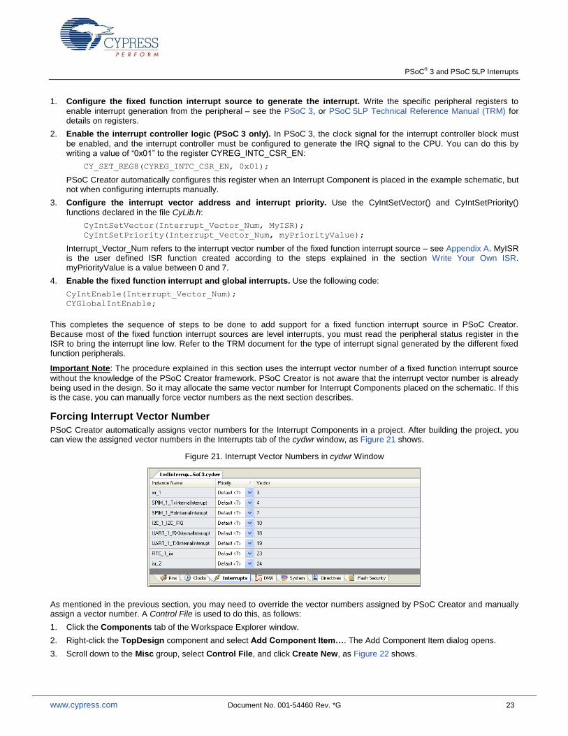
Forcing Interrupt Vector Number
PSoC Creator automatically assigns vector numbers for the Interrupt Components in a project. After building the project, you can view the assigned vector numbers in the Interrupts tab of the cydwr window, as Figure 21 shows.
Figure 21. Interrupt Vector Numbers in cydwr Window
As mentioned in the previous section, you may need to override the vector numbers assigned by PSoC Creator and manually assign a vector number. A Control File is used to do this, as follows:
1. Click the Components tab of the Workspace Explorer window.
2. Right-click the TopDesign component and select Add Component Item…. The Add Component Item dialog opens.
3. Scroll down to the Misc group, select Control File, and click Create New, as Figure 22 shows.
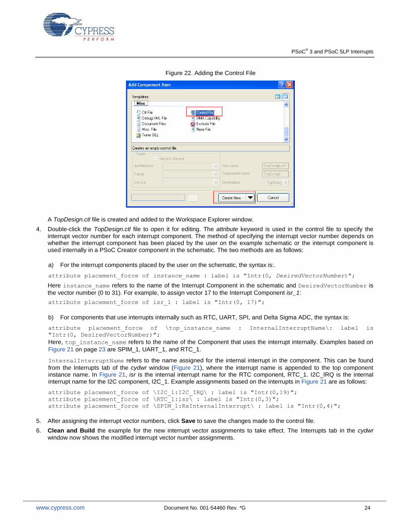
PSoC® 3 and PSoC 5LP Interrupts
www.cypress.com Document No. 001-54460 Rev. *G 24
Figure 22. Adding the Control File
A TopDesign.ctl file is created and added to the Workspace Explorer window.
4. Double-click the TopDesign.ctl file to open it for editing. The attribute keyword is used in the control file to specify the interrupt vector number for each interrupt component. The method of specifying the interrupt vector number depends on whether the interrupt component has been placed by the user on the example schematic or the interrupt component is used internally in a PSoC Creator component in the schematic. The two methods are as follows:
a) For the interrupt components placed by the user on the schematic, the syntax is:.
attribute placement_force of instance_name : label is "Intr(0, DesiredVectorNumber)";
Here instance_name refers to the name of the Interrupt Component in the schematic and DesiredVectorNumber is
the vector number (0 to 31). For example, to assign vector 17 to the Interrupt Component isr_1:
attribute placement_force of isr_1 : label is "Intr(0, 17)";
b) For components that use interrupts internally such as RTC, UART, SPI, and Delta Sigma ADC, the syntax is:
attribute placement_force of \top_instance_name : InternalInterruptName\: label is
"Intr(0, DesiredVectorNumber)";
Here, top_instance_name refers to the name of the Component that uses the interrupt internally. Examples based on
Figure 21 on page 23 are SPIM_1, UART_1, and RTC_1.
InternalInterruptName refers to the name assigned for the internal interrupt in the component. This can be found
from the Interrupts tab of the cydwr window (Figure 21), where the interrupt name is appended to the top component instance name. In Figure 21, isr is the internal interrupt name for the RTC component, RTC_1. I2C_IRQ is the internal interrupt name for the I2C component, I2C_1. Example assignments based on the interrupts in Figure 21 are as follows:
attribute placement_force of \I2C_1:I2C_IRQ\ : label is "Intr(0,19)";
attribute placement_force of \RTC_1:isr\ : label is "Intr(0,3)";
attribute placement_force of \SPIM_1:RxInternalInterrupt\ : label is "Intr(0,4)";
5. After assigning the interrupt vector numbers, click Save to save the changes made to the control file.
6. Clean and Build the example for the new interrupt vector assignments to take effect. The Interrupts tab in the cydwr
window now shows the modified interrupt vector number assignments.
PSoC® 3 and PSoC 5LP Interrupts
www.cypress.com Document No. 001-54460 Rev. *G 25
Summary
Interrupts are commonly used in embedded applications. For system-on-chip architectures such as those of PSoC 3, and PSoC 5LP, interrupts play the critical role of communicating the status of on-chip peripherals to the CPU. This application note has provided the information needed to quickly and easily create interrupt based PSoC Creator projects. In addition, advanced interrupt features were also explained.
Project Summary
AN54460.cywrk:
This workspace contains four code examples to demonstrate the different topics explained in this application note.
A_InterruptExample: Demonstrates a simple
application using a timer interrupt to toggle a pin.
B_PICU: Demonstrates the use of Port Interrupt
Control Unit (PICU) interrupt and using multiple interrupts.
C_LVD: Demonstrates how to use the Global Signal
Reference Component, using the Low Voltage Detect (LVD) interrupt as an example.
D_SysTick: (For PSoC 5LP only) Demonstrates how to use the SysTick interrupt in the Cortex-M3 CPU.
About the Author
Name: Vivek Shankar Kannan
Title: Applications Engineer Sr
PSoC® 3 and PSoC 5LP Interrupts
www.cypress.com Document No. 001-54460 Rev. *G 26
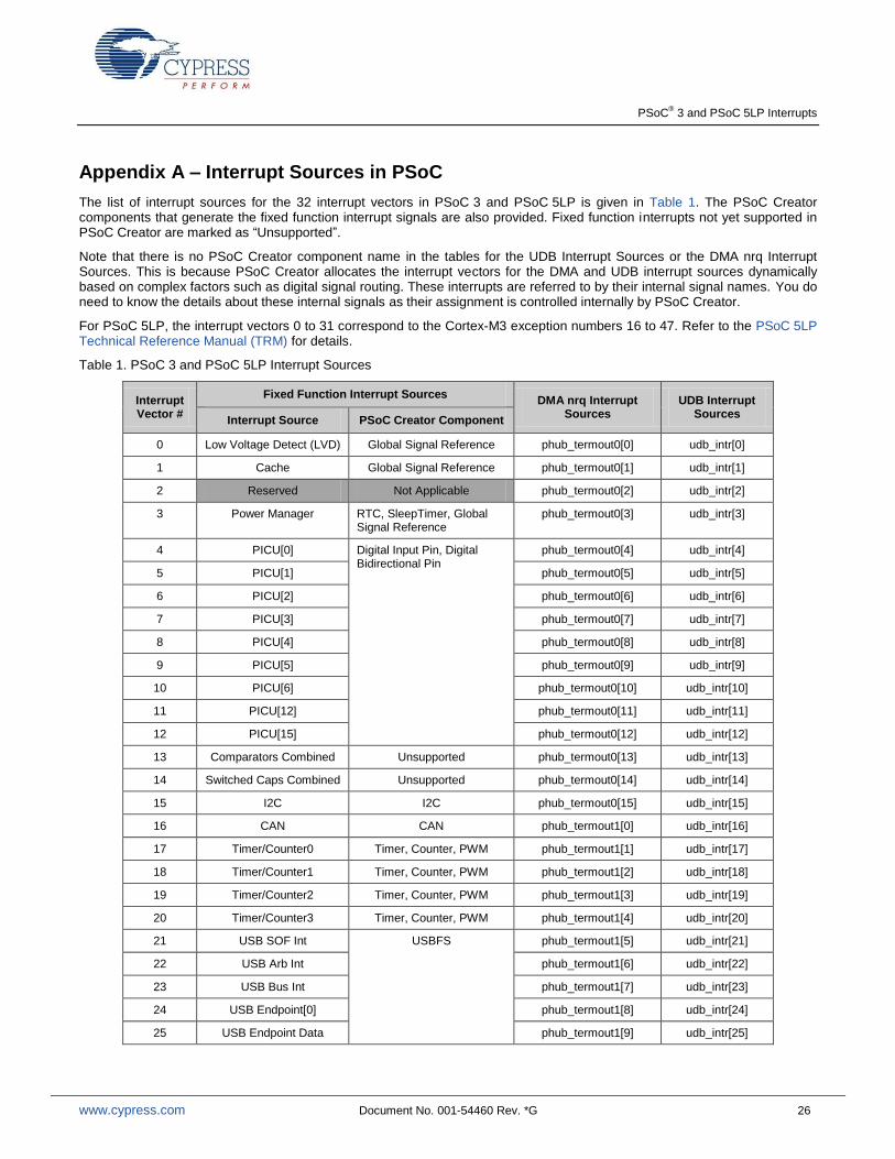
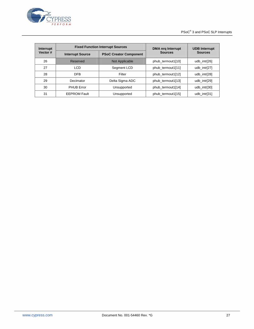
Appendix A – Interrupt Sources in PSoC
The list of interrupt sources for the 32 interrupt vectors in PSoC 3 and PSoC 5LP is given in Table 1. The PSoC Creator components that generate the fixed function interrupt signals are also provided. Fixed function interrupts not yet supported in PSoC Creator are marked as “Unsupported”.
Note that there is no PSoC Creator component name in the tables for the UDB Interrupt Sources or the DMA nrq Interrupt Sources. This is because PSoC Creator allocates the interrupt vectors for the DMA and UDB interrupt sources dynamically based on complex factors such as digital signal routing. These interrupts are referred to by their internal signal names. You do need to know the details about these internal signals as their assignment is controlled internally by PSoC Creator.
For PSoC 5LP, the interrupt vectors 0 to 31 correspond to the Cortex-M3 exception numbers 16 to 47. Refer to the PSoC 5LP Technical Reference Manual (TRM) for details.
Table 1. PSoC 3 and PSoC 5LP Interrupt Sources
Interrupt Vector #
Fixed Function Interrupt Sources DMA nrq Interrupt
Sources UDB Interrupt
Sources Interrupt Source PSoC Creator Component
0 Low Voltage Detect (LVD) Global Signal Reference phub_termout0[0] udb_intr[0]
1 Cache Global Signal Reference phub_termout0[1] udb_intr[1]
2 Reserved Not Applicable phub_termout0[2] udb_intr[2]
3 Power Manager RTC, SleepTimer, Global Signal Reference
phub_termout0[3] udb_intr[3]
4 PICU[0] Digital Input Pin, Digital Bidirectional Pin
phub_termout0[4] udb_intr[4]
5 PICU[1] phub_termout0[5] udb_intr[5]
6 PICU[2] phub_termout0[6] udb_intr[6]
7 PICU[3] phub_termout0[7] udb_intr[7]
8 PICU[4] phub_termout0[8] udb_intr[8]
9 PICU[5] phub_termout0[9] udb_intr[9]
10 PICU[6] phub_termout0[10] udb_intr[10]
11 PICU[12] phub_termout0[11] udb_intr[11]
12 PICU[15] phub_termout0[12] udb_intr[12]
13 Comparators Combined Unsupported phub_termout0[13] udb_intr[13]
14 Switched Caps Combined Unsupported phub_termout0[14] udb_intr[14]
15 I2C I2C phub_termout0[15] udb_intr[15]
16 CAN CAN phub_termout1[0] udb_intr[16]
17 Timer/Counter0 Timer, Counter, PWM phub_termout1[1] udb_intr[17]
18 Timer/Counter1 Timer, Counter, PWM phub_termout1[2] udb_intr[18]
19 Timer/Counter2 Timer, Counter, PWM phub_termout1[3] udb_intr[19]
20 Timer/Counter3 Timer, Counter, PWM phub_termout1[4] udb_intr[20]
21 USB SOF Int USBFS phub_termout1[5] udb_intr[21]
22 USB Arb Int phub_termout1[6] udb_intr[22]
23 USB Bus Int phub_termout1[7] udb_intr[23]
24 USB Endpoint[0] phub_termout1[8] udb_intr[24]
25 USB Endpoint Data phub_termout1[9] udb_intr[25]
PSoC® 3 and PSoC 5LP Interrupts
www.cypress.com Document No. 001-54460 Rev. *G 27
Interrupt Vector #
Fixed Function Interrupt Sources DMA nrq Interrupt
Sources UDB Interrupt
Sources Interrupt Source PSoC Creator Component
26 Reserved Not Applicable phub_termout1[10] udb_intr[26]
27 LCD Segment LCD phub_termout1[11] udb_intr[27]
28 DFB Filter phub_termout1[12] udb_intr[28]
29 Decimator Delta Sigma ADC phub_termout1[13] udb_intr[29]
30 PHUB Error Unsupported phub_termout1[14] udb_intr[30]
31 EEPROM Fault Unsupported phub_termout1[15] udb_intr[31]
PSoC® 3 and PSoC 5LP Interrupts
www.cypress.com Document No. 001-54460 Rev. *G 28
Appendix B - Re-Entrant Functions in PSoC 3
A re-entrant function is one that can be executed by multiple separate processes, such as main and an ISR, at the same time. For example, when a re-entrant function is being executed by main, an interrupt can occur and the ISR can call the same function.
Function re-entrancy is a standard feature of the C programming language, and is supported by the PSoC 5LP compilers. However due to limitations in the PSoC 3 8051 CPU, function re-entrancy is not usually implemented by the the Keil C51 compiler. This section explains the procedure for handling re-entrant functions with the Keil C51 compiler.
Re-Entrancy in Keil C51 Compiler
Due to the limited amount of stack and RAM space available in the PSoC 3’s 8051 CPU, the Keil C51 compiler considers functions as non re-entrant by default. The Keil compiler stores the function arguments and the local variables in fixed memory locations. Simultaneous calls to the function use the same memory locations which can cause function arguments and local variables to become corrupted.
While not re-entrant by default, functions can be made to support re-entrancy on an individual basis. The Keil compiler creates a separate stack on which the function’s local variables and arguments are stored. The pointer to this stack is adjusted on function calls so that multiple calls to the function are executed correctly. The re-entrant stack is created in the xdata memory space (SRAM memory space in PSoC 3).
If a re-entrant function is present in the PSoC Creator project, the KeilStart.a51 file of the project has auto-generated code to enable the re-entrant stack and initialize the stack pointer:
XBPSTACK EQU 1
XBPSTACKTOP EQU CYDEV_SRAM_SIZE
The first statement locates the stack in the xdata memory space (SRAM memory). The second statement assigns the top-of-the-stack address to the last byte of the SRAM. This is because the re-entrant stack pointer grows downward. Since the stack pointer is assigned to the last address of SRAM, the risk of the stack overwriting variables in SRAM is minimized.
Re-entrancy Support in PSoC Creator
The procedure to make a function re-entrant in PSoC Creator depends on whether the function is an API generated by PSoC Creator, a user defined function, or a function associated with a custom component created by the user. The different procedures are explained in the following sections.
Making Generated API Functions Re -entrant
These are the functions associated with the source code generated by PSoC Creator, as in the Component APIs. PSoC Creator allows you to specify which of the generated API functions should be made re-entrant, in a ‘re-entrancy file’ (cyre file).
This file specifies which functions should be made re-entrant. During the build process, functions noted in the re-entrancy file are automatically marked to support re-entrancy.
Most functions in the API files are candidates for re-entrancy. If a function cannot be made re-entrant, comments in the component source files indicate that the function is not a candidate for re-entrancy. This may be due to the fact that the function might use global or static variables, or call other functions, which cannot be made re-entrant.
PSoC® 3 and PSoC 5LP Interrupts
www.cypress.com Document No. 001-54460 Rev. *G 29
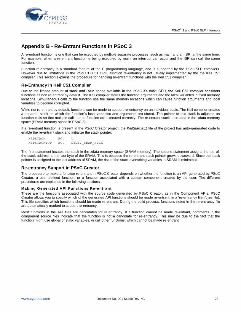
To add a cyre file to a project:
1. Right-click on the project in the Workspace Explorer, and select Add > New Item.
2. In the New Item dialog, select the ‘Keil Re-entrancy File’ and click OK (see Figure 23). The Project_Name.cyre file opens
in the code editor.
Figure 23. Adding a cyre File to a Project
To enter re-entrant functions:
3. Type a single function name in each line in the cyre file – only one function name per line. Note that only the function name needs to be entered in the cyre file, and the function name is case sensitive. The function return type or the brackets used to indicate a function should not be entered in the cyre file. For example:
ADC_Start
PWM_Start
4. Save the cyre file when complete.
Making User Defined Functions Re -entrant
These are functions that the you define as part of your application code. The cyre file cannot be used for specifying user
defined functions as re-entrant. To support re-entrancy for user defined functions, use the CYREENTRANT macro from
cytypes.h as part of the function prototype, and also the function definition. For the Keil tool chain, this evaluates to the
REENTRANT keyword, while for all other tool chains it evaluates to nothing. This allows the code to function properly across
multiple tool chains and multiple device families. The following example shows how to make a user defined function Foo re-
entrant.
void Foo(void) CYREENTRANT;
void Foo(void) CYREENTRANT
{
. . .
}
PSoC® 3 and PSoC 5LP Interrupts
www.cypress.com Document No. 001-54460 Rev. *G 30
Making Custom Component API Functions Re-entrant
These are the functions that are part of the Component source and header files that the user creates. PSoC Creator allows you to create and use your own Components.
When creating a custom component, any function in the source file and the header file of the component can be made to support re-entrancy using the build expression
`=ReentrantKeil($INSTANCE_NAME . “_FunctionName)”`
Replace the FunctionName in the build expression with the actual function name; all other fields must be left unchanged. Both the function declaration in the .h file and the function definition in the .c file must include this expression. This allows the function to behave in the same manner as other components shipped with PSoC Creator. By default, it is a standard function; however, the user can make it re-entrant by adding the function name to the *.cyre file (see the section Making Generated API Functions Re-entrant).
Original function declaration and definition:
void `$INSTANCE_NAME`_Foo (void);
void `$INSTANCE_NAME`_Foo (void)
{
. . .
}
Modified re-entrant function:
void `$INSTANCE_NAME`_Foo(void) `=ReentrantKeil($INSTANCE_NAME . “_Foo”)`;
void `$INSTANCE_NAME`_Foo(void) `=ReentrantKeil($INSTANCE_NAME . “_Foo”)`
{
. . .
}
Determining Re-entrant Functions
You must mark a function as re-entrant only when the Keil compiler allocates RAM space for the function, in addition to being called concurrently. The Keil compiler can help determine which functions should be marked re-entrant. When the optimization level is set to 2 or higher and a build is performed, the compiler outputs a warning for each function that can be called simultaneously that is not marked as re-entrant.
Warning: L15 MULTIPLE CALL TO FUNCTION MYFUNCTION/MAIN ?C_C51STARTUP ISR_1_INTERRUPT/ISR_1
In this warning message, L15 MULTIPLE CALL TO FUNCTION refers to the re-entrancy warning. MYFUNCTION/MAIN refers
to the fact that the function MyFunction, defined in the file main.c, is the one that is being called concurrently. One of the
callers of MyFunction is the main code. The Keil compiler uses the term ?C_C51STARTUP to refer to the main flow of
execution that originates from the main() function.
The second caller of MyFunction is the function isr_1_Interrupt in the file isr_1.c, which is indicated by
ISR_1_INTERRUPT/ISR_1. This is the interrupt service routine. Therefore, the function MyFunction needs to be made re-
entrant. Notice that the Keil compiler re-entrancy warnings always refer to the function names and file names in capital letters even when they are in a different case.
Another example of the warning message is:
WARNING: L15: MULTIPLE CALL TO FUNCTION DELAY/TIMING ISR_1/INTERRUPT_1 ISR_2/INTERRUPT_2
In this warning message, the function Delay() in the file Timing.c is concurrently called from two interrupt service routines -
the function isr_1() in the file Interrupt_1.c, and also the function isr_2() in the file Interrupt_2.c. So, the function
Delay() must be made re-entrant.
The warning message formats are according to how they appear in the Notice List window of PSoC Creator. The format is slightly different in the Output window and the map file of the example. In both the Output window and the map file, the earl ier warning that was shown would be in the following format.

PSoC® 3 and PSoC 5LP Interrupts
www.cypress.com Document No. 001-54460 Rev. *G 31
Warning: L15 MULTIPLE CALL TO FUNCTION NAME: MYFUNCTION/MAIN CALLER1: ?C_C51STARTUP CALLER2: ISR_1_INTERRUPT/ISR_1
Re-entrancy warnings should never be ignored, even if those warnings may not be applicable under all the cases. As an example, the interrupt might be disabled when the function is called from the main code. So, there is no possibility of the function being called concurrently from both the main and the ISR. However, the Keil linker will not be able to identify these scenarios. It still throws the re-entrancy warnings seeing the concurrent function calls. Ignoring the re-entrancy warnings, even if not applicable, may cause the linker to allocate the same memory locations for different execution flows during data overlaying. This may potentially result in data corruption and the functionality of the code can get affected.
PSoC® 3 and PSoC 5LP Interrupts
www.cypress.com Document No. 001-54460 Rev. *G 32
Document History
Document Title: PSoC® 3 and PSoC 5LP Interrupts – AN54460
Document Number: 001-54460
Revision ECN Orig. of Change
Submission Date
Description of Change
** 2733933 VVSK 07/09/2009 New Application Note
*A 2764026 VVSK 09/15/2009 Updated Figures 7, 8, and 9.
Added content in “Interrupt Priority Configuration” section on page 4.
Added content in the section “Re-entrant Functions” on page 7.
*B 2969819 VVSK 08/25/2010 Content and projects updated for Beta 5 of PSoC Creator.
*C 3452593 VVSK 12/01/2011 Complete rewrite of the application note including support for PSoC Creator 2.0.
*D 3709462 VVSK 08/10/2012 Updated Interrupt Component Configuration, updated Interrupt Projects
Four PSoC Creator projects are provided as part of this application note that demonstrate basic interrupt, Port Interrupt Control Unit (PICU), Low Voltage Detect (LVD), and SysTick interrupts in PSoC 3 and PSoC 5LP. Note that SysTick is a feature of the Cortex-M3 CPU and is not available in PSoC 3.
Simple Interrupt Project).
Updated in new template.
*E 3809428 VVSK 11/12/2012 Updated for PSoC 5LP
*F 4028654 MKEA 06/15/2013 Updated for PSoC 4, PSoC Creator 2.2 SP1, Global Signal Reference Component, and Cortex SysTick
*G 4483429 VVSK 08/25/2014 Updated title.
Updated content to make the AN specific to PSoC 3 and PSoC 5 LP. Removed PSoC 4-specific content.
Modified abstract, introduction, added sections on interrupt latency, debugging techniques, and added code snippets
PSoC® 3 and PSoC 5LP Interrupts
www.cypress.com Document No. 001-54460 Rev. *G 33
Worldwide Sales and Design Support
Cypress maintains a worldwide network of offices, solution centers, manufacturer’s representatives, and distributors. To find the office closest to you, visit us at Cypress Locations.
Products
Automotive cypress.com/go/automotive
Clocks & Buffers cypress.com/go/clocks
Interface cypress.com/go/interface
Lighting & Power Control cypress.com/go/powerpsoc cypress.com/go/plc
Memory cypress.com/go/memory
PSoC cypress.com/go/psoc
Touch Sensing cypress.com/go/touch
USB Controllers cypress.com/go/usb
Wireless/RF cypress.com/go/wireless
PSoC® Solutions
psoc.cypress.com/solutions
PSoC 1 | PSoC 3 | PSoC 4 | PSoC 5LP
Cypress Developer Community
Community | Forums | Blogs | Video | Training
Technical Support
cypress.com/go/support
PSoC is a registered trademark of Cypress Semiconductor Corp. All other trademarks or registered trademarks referenced herein are the property of their respective owners.
Cypress Semiconductor 198 Champion Court San Jose, CA 95134-1709
Phone : 408-943-2600 Fax : 408-943-4730 Website : www.cypress.com
© Cypress Semiconductor Corporation, 2009 - 2014. The information contained herein is subject to change without notice. Cypress Semiconductor Corporation assumes no responsibility for the use of any circuitry other than circuitry embodied in a Cypress product. Nor does it convey or imply any license under patent or other rights. Cypress products are not warranted nor intended to be used for medical, life support, life saving, critical control or safety applications, unless pursuant to an express written agreement with Cypress. Furthermore, Cypress does not authorize its products for use as critical components in life-support systems where a malfunction or failure may reasonably be expected to result in significant injury to the user. The inclusion of Cypress products in life-support systems application implies that the manufacturer assumes all risk of such use and in doing so indemnifies Cypress against all charges. This Source Code (software and/or firmware) is owned by Cypress Semiconductor Corporation (Cypress) and is protected by and subject to worldwide patent protection (United States and foreign), United States copyright laws and international treaty provisions. Cypress hereby grants to licensee a personal, non-exclusive, non-transferable license to copy, use, modify, create derivative works of, and compile the Cypress Source Code and derivative works for the sole purpose of creating custom software and or firmware in support of licensee product to be used only in conjunction with a Cypress integrated circuit as specified in the applicable agreement. Any reproduction, modification, translation, compilation, or representation of this Source Code except as specified above is prohibited without the express written permission of Cypress. Disclaimer: CYPRESS MAKES NO WARRANTY OF ANY KIND, EXPRESS OR IMPLIED, WITH REGARD TO THIS MATERIAL, INCLUDING, BUT NOT LIMITED TO, THE IMPLIED WARRANTIES OF MERCHANTABILITY AND FITNESS FOR A PARTICULAR PURPOSE. Cypress reserves the right to make changes without further notice to the materials described herein. Cypress does not assume any liability arising out of the application or use of any product or circuit described herein. Cypress does not authorize its products for use as critical components in life-support systems where a malfunction or failure may reasonably be expected to result in significant injury to the user. The inclusion of Cypress’ product in a life-support systems application implies that the manufacturer assumes all risk of such use and in doing so indemnifies Cypress against all charges. Use may be limited by and subject to the applicable Cypress software license agreement.