Embed Size (px)
Citation preview

87
WWW.PSI-PRODUCTS.COM
WIDE RANGE OF SKID HEIGHTS MAKES THE CENTERING EASY
MEETS ALL REQUIREMENTS OF THE CATHODIC PIPE PROTECTION
EASY PENETRATION OF CARRIER PIPE WITH MINIMIZED FRICTION
PSI CASING SPACERS SYSTEM DSI

88
PSI Casing Spacers System DSI
GENERAL INFORMATION
Polypropylen casing spacers are universally applicable in the installation of pipelines when a media pipe runs through a casing pipe.
Plastic insulators provide many advantages for these applications:
Plastic insulators are suitable for all pipe diameters from 25 mm upwards and many skid heights are available to suit specifi c requirements.
More content can be found on www.psi-products.com
• Easy penetration of carrier pipe. The insulator’s friction coefficient is reduced to a minimum because they are made of plastic.
• The minimized friction prevents the media pipe from taking damage inside the casing pipe.
• A wide range of skid heights ensures concentricity of the media pipe inside the casing pipe.
• Excellent insulation characteristics. All requirements of cathodic pipe protection are met.
• For an optimal pipe support, we recommend to assemble a double ring at the beginning and at the end of each crossing.
Type PA/PE Type GKO-mkType AZ/AC
Type MA Type RGV Type GKO-gl/gs
89
PSI Casing Spacers System DSI
TECHNICAL DATA
Materials
Polypropylene has a good friction coeffi cient due to its waxy surface with good sliding properties. The sliding friction coeffi cient is approx. 0.2 for PP on steel. In comparison to this, steel on steel is approx. 0.5. Therefore the abrasion is reduced to a minimum. The material is strong and yet fl exible and is therefore resistant to stress cracking. Flexibility of the body, stability of the skid form and excellent dielectric insulation are some more of the good characteristics of this material. Polypropylene has a higher temperature resistance compared to polyethylene. The base material is resistant from -20 °C to +100 °C
Installation notes
Plastic insulator rings are normally installed with the following spacing in between the rings:
• Pipe diameter up to 300 mm in 2.5 m support distance• Pipe diameter 301 - 600 mm in 2.0 m support distance• Pipe diameter of more than 600 mm in 1.5 m support distance
The installation distances are also dependent on the spans specifi cations of the respective pipe manufacturer.
In particular cases, the ring distance may be modifi ed after having examined the installation situation.
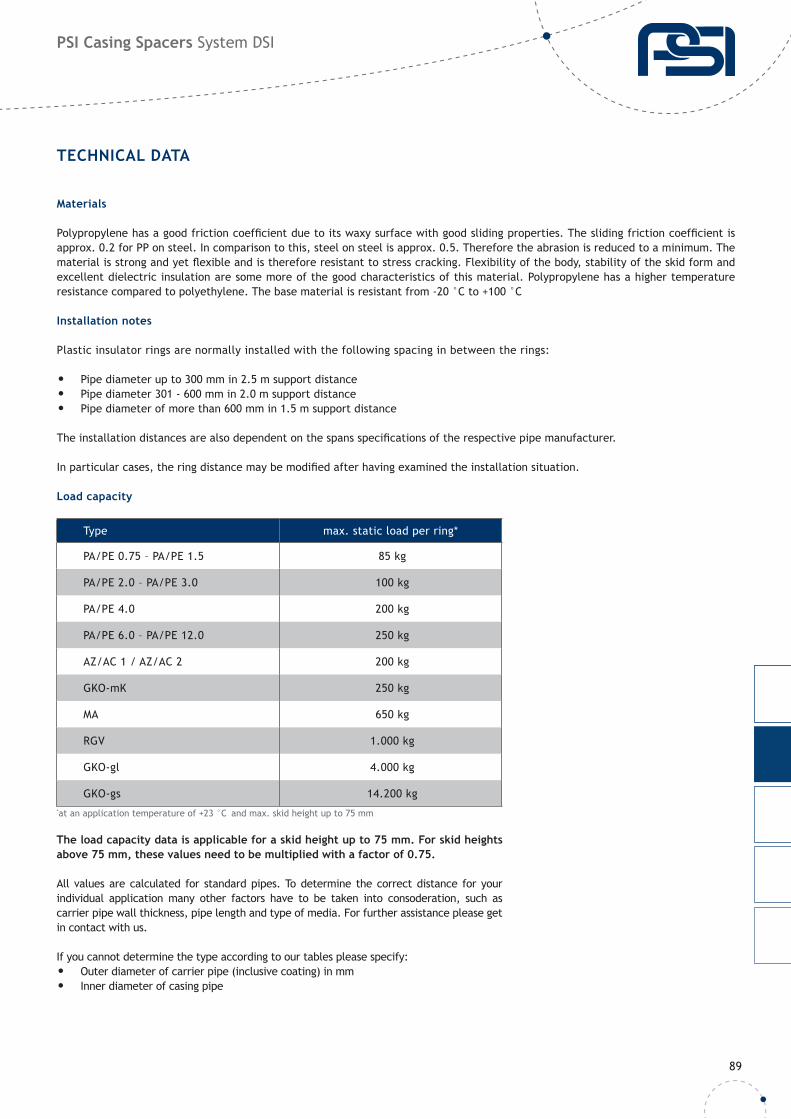
Load capacity
The load capacity data is applicable for a skid height up to 75 mm. For skid heights above 75 mm, these values need to be multiplied with a factor of 0.75.
All values are calculated for standard pipes. To determine the correct distance for your individual application many other factors have to be taken into consoderation, such as carrier pipe wall thickness, pipe length and type of media. For further assistance please get in contact with us.
If you cannot determine the type according to our tables please specify:• Outer diameter of carrier pipe (inclusive coating) in mm• Inner diameter of casing pipe
Type max. static load per ring*
PA/PE 0.75 – PA/PE 1.5 85 kg
PA/PE 2.0 – PA/PE 3.0 100 kg
PA/PE 4.0 200 kg
PA/PE 6.0 – PA/PE 12.0 250 kg
AZ/AC 1 / AZ/AC 2 200 kg
GKO-mK 250 kg
MA 650 kg
RGV 1.000 kg
GKO-gl 4.000 kg
GKO-gs 14.200 kg*at an application temperature of +23 °C and max. skid height up to 75 mm
90
PSI Casing SpacersType PA/PE System DSI
GENERAL INFORMATION
More content can be found on www.psi-products.com
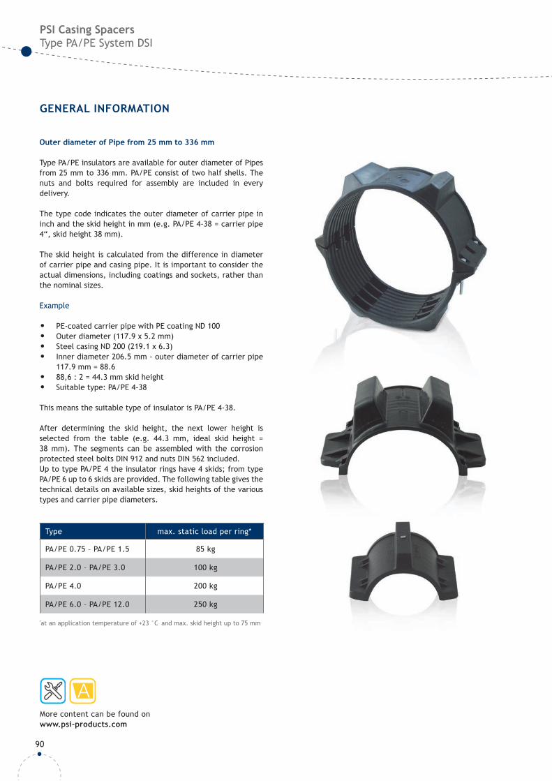
Outer diameter of Pipe from 25 mm to 336 mm
Type PA/PE insulators are available for outer diameter of Pipes from 25 mm to 336 mm. PA/PE consist of two half shells. The nuts and bolts required for assembly are included in every delivery.
The type code indicates the outer diameter of carrier pipe in inch and the skid height in mm (e.g. PA/PE 4-38 = carrier pipe 4“, skid height 38 mm).
The skid height is calculated from the difference in diameter of carrier pipe and casing pipe. It is important to consider the actual dimensions, including coatings and sockets, rather than the nominal sizes.
Example
• PE-coated carrier pipe with PE coating ND 100• Outer diameter (117.9 x 5.2 mm)• Steel casing ND 200 (219.1 x 6.3)• Inner diameter 206.5 mm - outer diameter of carrier pipe
117.9 mm = 88.6• 88,6 : 2 = 44.3 mm skid height• Suitable type: PA/PE 4-38
This means the suitable type of insulator is PA/PE 4-38.
After determining the skid height, the next lower height is selected from the table (e.g. 44.3 mm, ideal skid height = 38 mm). The segments can be assembled with the corrosion protected steel bolts DIN 912 and nuts DIN 562 included.Up to type PA/PE 4 the insulator rings have 4 skids; from type PA/PE 6 up to 6 skids are provided. The following table gives the technical details on available sizes, skid heights of the various types and carrier pipe diameters.
Type max. static load per ring*
PA/PE 0.75 – PA/PE 1.5 85 kg
PA/PE 2.0 – PA/PE 3.0 100 kg
PA/PE 4.0 200 kg
PA/PE 6.0 – PA/PE 12.0 250 kg
*at an application temperature of +23 °C and max. skid height up to 75 mm
91
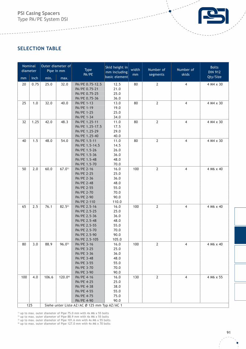
PSI Casing Spacers Type PA/PE System DSI
SELECTION TABLE
Nominal diameter
Outer diameter of Pipe in mm Type
PA/PE
Skid height in mm includingbasic element
widthmm
Number ofsegments
Number of skids
BoltsDIN 912Qty/Sizemm Inch min. max.
20 0.75 25.0 32.0 PA/PE 0.75-12.5 12.5 80 2 4 4 M4 x 30PA/PE 0.75-21 21.0PA/PE 0.75-25 25.0PA/PE 0.75-36 36.0
25 1.0 32.0 40.0 PA/PE 1-13 13.0 80 2 4 4 M4 x 30PA/PE 1-19 19.0PA/PE 1-25 25.0PA/PE 1-34 34.0
32 1.25 42.0 48.3 PA/PE 1.25-11 11.0 80 2 4 4 M4 x 30PA/PE 1.25-17.5 17.5PA/PE 1.25-29 29.0PA/PE 1.25-40 40.0
40 1.5 48.0 54.0 PA/PE 1.5-11 11.0 80 2 4 4 M4 x 30PA/PE 1.5-14.5 14.5PA/PE 1.5-26 26.0PA/PE 1.5-36 36.0PA/PE 1.5-48 48.0PA/PE 1.5-70 70.0
50 2.0 60.0 67.01) PA/PE 2-16 16.0 100 2 4 4 M6 x 40PA/PE 2-25 25.0PA/PE 2-36 36.0PA/PE 2-48 48.0PA/PE 2-55 55.0PA/PE 2-70 70.0PA/PE 2-90 90.0PA/PE 2-110 110.0
65 2.5 76.1 82.52) PA/PE 2.5-16 16.0 100 2 4 4 M6 x 40PA/PE 2.5-25 25.0PA/PE 2.5-36 36.0PA/PE 2.5-48 48.0PA/PE 2.5-55 55.0PA/PE 2.5-70 70.0PA/PE 2.5-90 90.0PA/PE 2.5-105 105.0
80 3.0 88.9 96.03) PA/PE 3-16 16.0 100 2 4 4 M6 x 40PA/PE 3-25 25.0PA/PE 3-36 36.0PA/PE 3-48 48.0PA/PE 3-55 55.0PA/PE 3-70 70.0PA/PE 3-90 90.0
100 4.0 106.6 120.04) PA/PE 4-16 16.0 130 2 4 4 M6 x 55PA/PE 4-25 25.0PA/PE 4-38 38.0PA/PE 4-55 55.0PA/PE 4-75 75.0PA/PE 4-90 90.0
125 Siehe unter Liste AZ/AC Ø 125 mm Typ AZ/AC 1
1) up to max. outer diameter of Pipe 75.0 mm with 4x M6 x 55 bolts2) up to max. outer diameter of Pipe 88.9 mm with 4x M6 x 55 bolts3) up to max. outer diameter of Pipe 101.6 mm with 4x M6 x 55 bolts4) up to max. outer diameter of Pipe 127.0 mm with 4x M6 x 70 bolts

92
PSI Casing SpacersType PA/PE System DSI
SELECTION TABLE
Nominal diameter
Outer diameter of Pipe in mm Type
PA/PE
Skid height in mm includingbasic element
widthmm
Number ofsegments
Number of skids
BoltsDIN 912Qty/Sizemm Inch min. max.
150 6 160.0 178.0 PA/PE 6-16 16 130 2 6 4 M6 x 70PA/PE 6-25 25PA/PE 6-36 36PA/PE 6-55 55PA/PE 6-75* 75 4PA/PE 6-90* 90
200 193.7 210.0 PA/PE 7-16 16 175 2 6 4 M6 x 70PA/PE 7-25 25PA/PE 7-36 36PA/PE 7-55 55PA/PE 7-75 75PA/PE 7-90 90PA/PE 7-110 110
200 8 221.0 239.0 PA/PE 8-16 16 130 2 6 4 M6 x 70PA/PE 8-25 25PA/PE 8-36 36PA/PE 8-55* 55 6PA/PE 8-75* 75PA/PE 8-90* 90
250 244.5 260.0 PA/PE 9-16 16 175 2 6 4 M6 x 70PA/PE 9-25 25PA/PE 9-36 36PA/PE 9-55 55PA/PE 9-75 75PA/PE 9-90 90PA/PE 9-110 110
250 10 276.0 295.0 PA/PE 10-16 16 130 2 6 4 M6 x 70PA/PE 10-25 25PA/PE 10-36 36PA/PE 10-55* 55 4PA/PE 10-75* 75PA/PE 10-90* 90
315 298.5 315.0 PA/PE 11-16 16 175 2 6 4 M6 x 70PA/PE 11-25 25PA/PE 11-36 36PA/PE 11-55 55PA/PE 11-75 75PA/PE 11-90 90PA/PE 11-110 110
300 12 326.0 336.0 PA/PE 12-16 16 130 2 6 4 M6 x 70PA/PE 12-25 25PA/PE 12-36 36PA/PE 12-55* 55 4PA/PE 12-75* 75PA/PE 12-90* 90
Sectional drawing of segment.PA/PE 0.75 to PA/PE 4Ring with a total of 4 skids
Sectional drawing of segment.PA/PE 6 to PA/PE 12Ring with a total of 6 skids
*Plug-in skid
Anti Sliding Tape against slipping of spacers, see next page
93
PSI Casing SpacersType PA/PE System DSI
ACCESSORIES
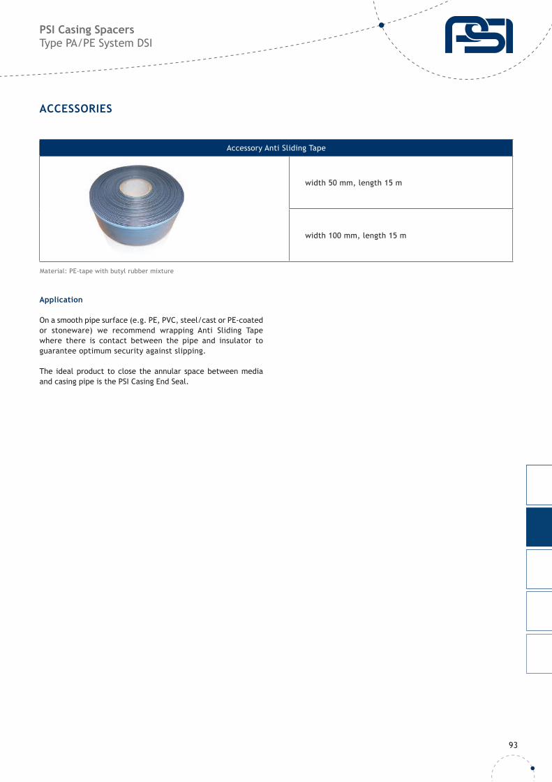
Accessory Anti Sliding Tape
width 50 mm, length 15 m
width 100 mm, length 15 m
Material: PE-tape with butyl rubber mixture
Application
On a smooth pipe surface (e.g. PE, PVC, steel/cast or PE-coated or stoneware) we recommend wrapping Anti Sliding Tape where there is contact between the pipe and insulator to guarantee optimum security against slipping.
The ideal product to close the annular space between media and casing pipe is the PSI Casing End Seal.
94
PSI Casing Spacers Type AZ/AC System DSI
GENERAL INFORMATION
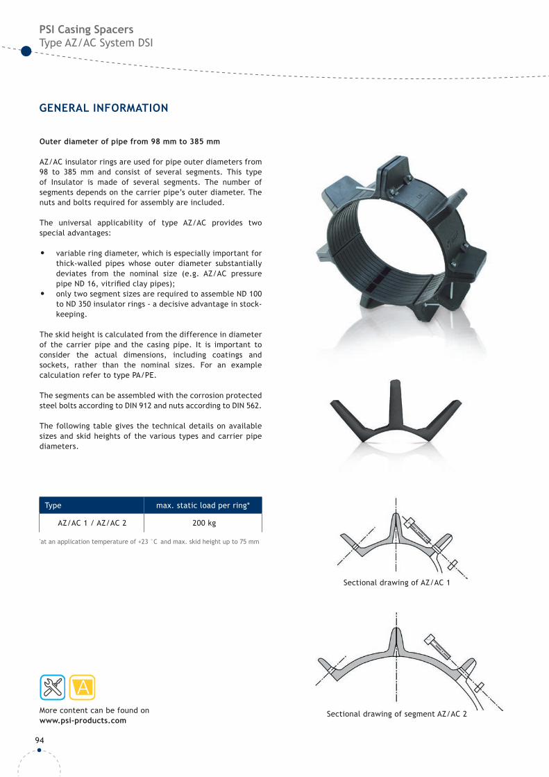
Outer diameter of pipe from 98 mm to 385 mm
AZ/AC insulator rings are used for pipe outer diameters from 98 to 385 mm and consist of several segments. This type of Insulator is made of several segments. The number of segments depends on the carrier pipe’s outer diameter. The nuts and bolts required for assembly are included.
The universal applicability of type AZ/AC provides two special advantages:
• variable ring diameter, which is especially important for thick-walled pipes whose outer diameter substantially deviates from the nominal size (e.g. AZ/AC pressure pipe ND 16, vitrifi ed clay pipes);
• only two segment sizes are required to assemble ND 100 to ND 350 insulator rings - a decisive advantage in stock-keeping.
The skid height is calculated from the difference in diameter of the carrier pipe and the casing pipe. It is important to consider the actual dimensions, including coatings and sockets, rather than the nominal sizes. For an example calculation refer to type PA/PE.
The segments can be assembled with the corrosion protected steel bolts according to DIN 912 and nuts according to DIN 562.
The following table gives the technical details on available sizes and skid heights of the various types and carrier pipe diameters.
Sectional drawing of AZ/AC 1
Sectional drawing of segment AZ/AC 2More content can be found on www.psi-products.com
Type max. static load per ring*
AZ/AC 1 / AZ/AC 2 200 kg
*at an application temperature of +23 °C and max. skid height up to 75 mm
95
PSI Casing SpacersType AZ/AC System DSI
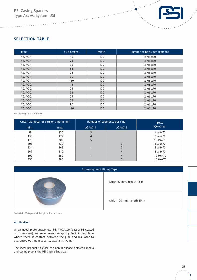
SELECTION TABLE
Type Skid height Width Number of bolts per segment
AZ/AC-1 16 130 2 M6 x70AZ/AC-1 25 130 2 M6 x70AZ/AC-1 36 130 2 M6 x70AZ/AC-1 55 130 2 M6 x70AZ/AC-1 75 130 2 M6 x70AZ/AC-1 90 130 2 M6 x70AZ/AC-1 110 130 2 M6 x70AZ/AC-2 16 130 2 M6 x70AZ/AC-2 25 130 2 M6 x70AZ/AC-2 36 130 2 M6 x70AZ/AC-2 55 130 2 M6 x70AZ/AC-2 75 130 2 M6 x70AZ/AC-2 90 130 2 M6 x70AZ/AC-2 110 130 2 M6 x70
Outer diameter of carrier pipe in mm Number of segments per ring BoltsQty/Sizemin. max. AZ/AC 1 AZ/AC 2
98 130 3 6 M6x70130 172 4 8 M6x70173 202 5 10 M6x70203 230 3 6 M6x70234 268 1 3 8 M6x70269 310 4 8 M6x70302 350 1 4 10 M6x70350 385 5 10 M6x70
Accessory Anti Sliding Tape
width 50 mm, length 15 m
width 100 mm, length 15 m
Material: PE-tape with butyl rubber mixture
Anti Sliding Tape see below
Application
On a smooth pipe surface (e.g. PE, PVC, steel/cast or PE-coated or stoneware) we recommend wrapping Anti Sliding Tape where there is contact between the pipe and insulator to guarantee optimum security against slipping.
The ideal product to close the annular space between media and casing pipe is the PSI Casing End Seal.

96
PSI Casing SpacersType GKO-mk System DSI - non-metallic
GENERAL INFORMATION
Subject to technical changes
More content can be found on www.psi-products.com
GKO-mk is the latest PSI casing spacer generation. Due to the bolt less wedge system the installation can be achieved quickly and easily. The fl exible design ensures suitability for all pipe diameters > 160 mm. If required, an additional support for cable ducts can be installed on the segments.
• Flexible design
• Non-metallic connection for simple and fast installation
• New wedge connection technology
PSI Anti Sliding Tape or similar products can be used to improve adhesion on smooth surfaces, or to balance pipe tolerances.
Type max. static load per ring*
GKO-mK 250 kg
*at an application temperature of +23 °C and max. skid height up to 75 mm
97
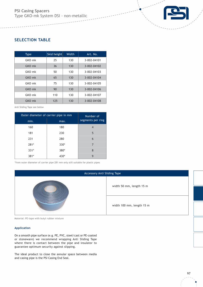
PSI Casing SpacersType GKO-mk System DSI - non-metallic
SELECTION TABLE
Outer diameter of carrier pipe in mm Number ofsegments per ringmin. max.
160 180 4
181 230 5
231 280 6
281* 330* 7
331* 380* 8
381* 430* 9
*from outer diameter of carrier pipe 281 mm only still suitable for plastic pipes
Type Skid height Width Art. No.
GKO mk 25 130 3-002-04101
GKO mk 36 130 3-002-04102
GKO mk 50 130 3-002-04103
GKO mk 65 130 3-002-04104
GKO mk 75 130 3-002-04105
GKO mk 90 130 3-002-04106
GKO mk 110 130 3-002-04107
GKO mk 125 130 3-002-04108
Accessory Anti Sliding Tape
width 50 mm, length 15 m
width 100 mm, length 15 m
Material: PE-tape with butyl rubber mixture
Anti Sliding Tape see below
Application
On a smooth pipe surface (e.g. PE, PVC, steel/cast or PE-coated or stoneware) we recommend wrapping Anti Sliding Tape where there is contact between the pipe and insulator to guarantee optimum security against slipping.
The ideal product to close the annular space between media and casing pipe is the PSI Casing End Seal.
98
PSI Casing SpacersType MA System DSI
GENERAL INFORMATION
More content can be found on www.psi-products.com
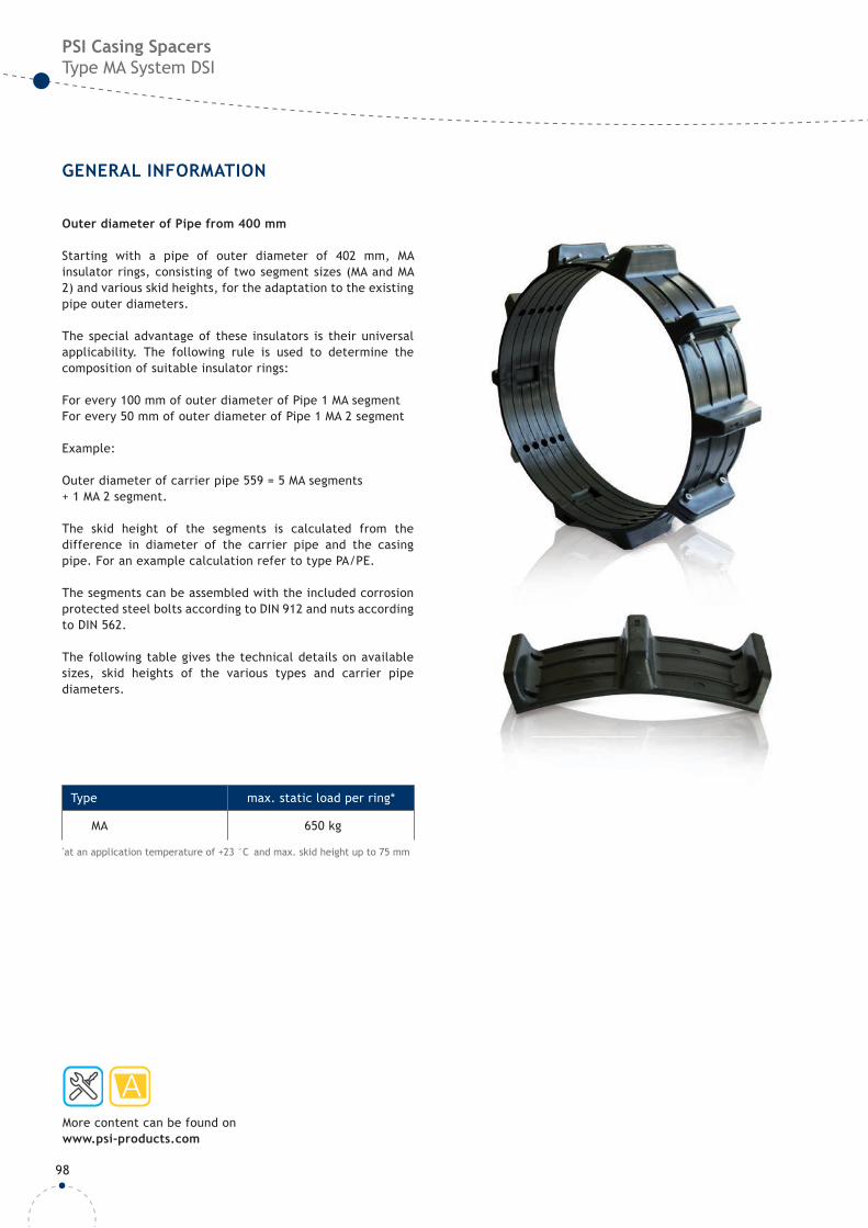
Outer diameter of Pipe from 400 mm
Starting with a pipe of outer diameter of 402 mm, MA insulator rings, consisting of two segment sizes (MA and MA 2) and various skid heights, for the adaptation to the existing pipe outer diameters.
The special advantage of these insulators is their universal applicability. The following rule is used to determine the composition of suitable insulator rings:
For every 100 mm of outer diameter of Pipe 1 MA segmentFor every 50 mm of outer diameter of Pipe 1 MA 2 segment
Example:
Outer diameter of carrier pipe 559 = 5 MA segments+ 1 MA 2 segment.
The skid height of the segments is calculated from the difference in diameter of the carrier pipe and the casing pipe. For an example calculation refer to type PA/PE.
The segments can be assembled with the included corrosion protected steel bolts according to DIN 912 and nuts according to DIN 562.
The following table gives the technical details on available sizes, skid heights of the various types and carrier pipe diameters.
Type max. static load per ring*
MA 650 kg
*at an application temperature of +23 °C and max. skid height up to 75 mm
99
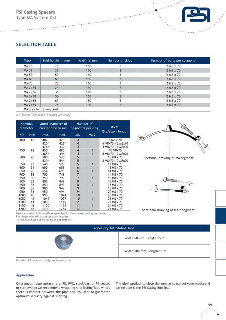
PSI Casing Spacers Type MA System DSI
SELECTION TABLE
Type Skid height in mm Width in mm Number of skids Number of bolts per segment
MA 25 25 160 3 2 M8 x 70MA 36 36 160 3 2 M8 x 70MA 50 50 160 3 2 M8 x 70MA 65 65 160 3 2 M8 x 70MA 75 75 160 3 2 M8 x 70MA 2/25 25 160 2 2 M8 x 70MA 2/36 36 160 2 2 M8 x 70MA 2/50 50 160 2 2 M8 x 70MA 2/65 65 160 2 2 M8 x 70MA 2/75 75 160 2 2 M8 x 70MA 2 as half a segment
Nominal diameter
Outer diameter ofcarrier pipe in mm
Number ofsegments per ring Bolts
Qty/size - lengthND inch min. max. MA MA 2
400 16 402 420 4 8 M8 x 70420* 426* 4 6 M8x70 + 2 M8x90426* 432* 4 4 M8x70 + 4 M8x90
450 18 450 485 4 1 10 M8x70485* 494* 4 1 8 M8x70 + 2 M8x90
500 20 500 530 5 10 M8 x 70530* 544* 5 8 M8x70 + 2 M8x90
550 22 548 599 5 1 12 M8 x 70600 24 600 653 6 12 M8 x 70650 26 654 699 6 1 14 M8 x 70700 28 700 749 7 14 M8 x 70750 30 750 799 7 1 16 M8 x 70800 32 800 849 8 16 M8 x 70850 34 850 899 8 1 18 M8 x 70900 36 900 949 9 18 M8 x 70950 38 950 994 9 1 20 M8 x 701000 40 995 1044 10 20 M8 x 701050 42 1045 1097 10 1 22 M8 x 701100 44 1098 1149 11 22 M8 x 701150 46 1150 1199 11 1 24 M8 x 701200 48 1200 1249 12 24 M8 x 70
Sectional drawing of MA segment
Sectional drawing of MA 2 segment
Material: PE-tape with butyl rubber mixture
Accessory Anti Sliding Tape
width 50 mm, length 15 m
width 100 mm, length 15 m
Anti Sliding Tape against slipping see below
Caution: Install bolt length as specifi ed for the corresponding segments.For larger nominal diameter upon request.* Please contact our inside sales department
Application
On a smooth pipe surface (e.g. PE, PVC, steel/cast or PE-coated or stoneware) we recommend wrapping Anti Sliding Tape where there is contact between the pipe and insulator to guarantee optimum security against slipping.
The ideal product to close the annular space between media and casing pipe is the PSI Casing End Seal.
100
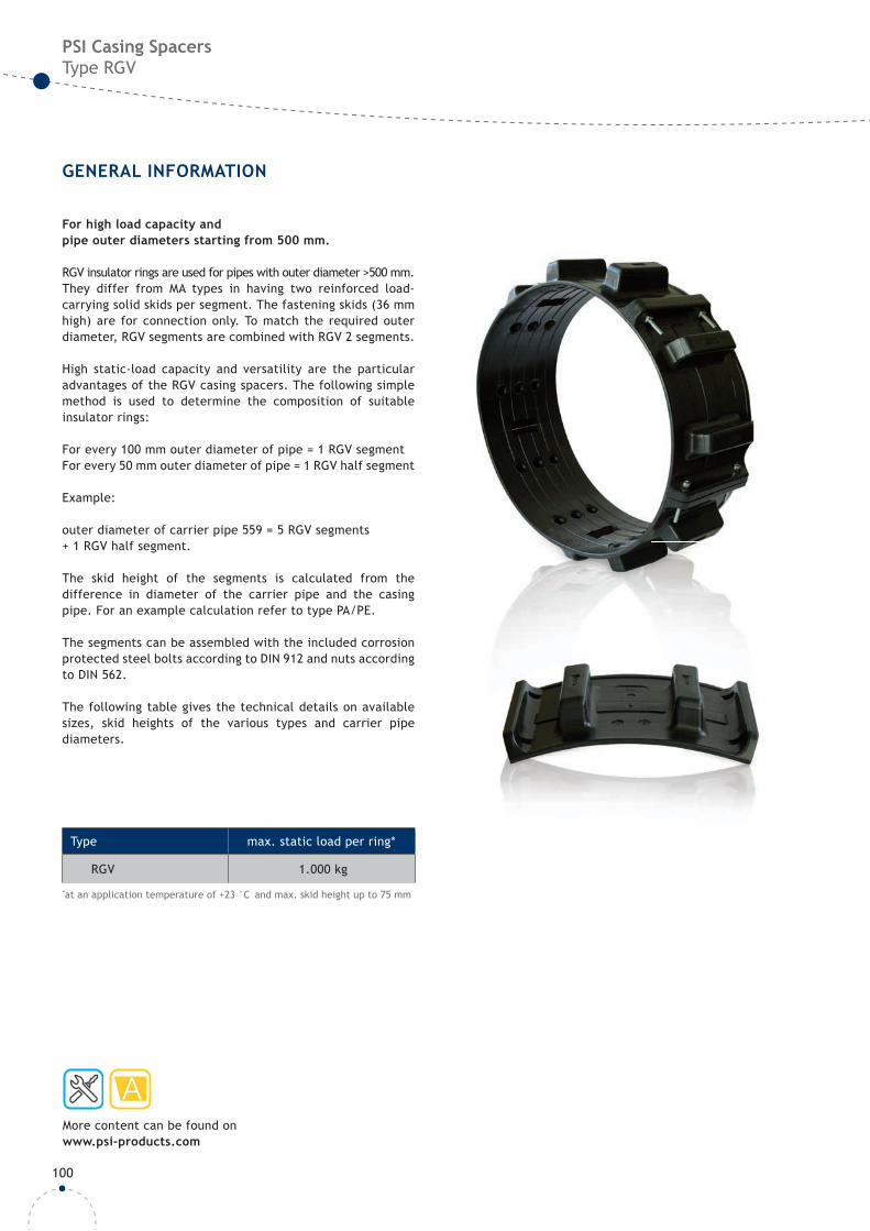
PSI Casing SpacersType RGV
GENERAL INFORMATION
More content can be found on www.psi-products.com
For high load capacity and pipe outer diameters starting from 500 mm.
RGV insulator rings are used for pipes with outer diameter >500 mm. They differ from MA types in having two reinforced load-carrying solid skids per segment. The fastening skids (36 mm high) are for connection only. To match the required outer diameter, RGV segments are combined with RGV 2 segments.
High static-load capacity and versatility are the particular advantages of the RGV casing spacers. The following simple method is used to determine the composition of suitable insulator rings:
For every 100 mm outer diameter of pipe = 1 RGV segmentFor every 50 mm outer diameter of pipe = 1 RGV half segment
Example:
outer diameter of carrier pipe 559 = 5 RGV segments+ 1 RGV half segment.
The skid height of the segments is calculated from the difference in diameter of the carrier pipe and the casing pipe. For an example calculation refer to type PA/PE.
The segments can be assembled with the included corrosion protected steel bolts according to DIN 912 and nuts according to DIN 562.
The following table gives the technical details on available sizes, skid heights of the various types and carrier pipe diameters.
Type max. static load per ring*
RGV 1.000 kg
*at an application temperature of +23 °C and max. skid height up to 75 mm
101
PSI Casing SpacersType RGV
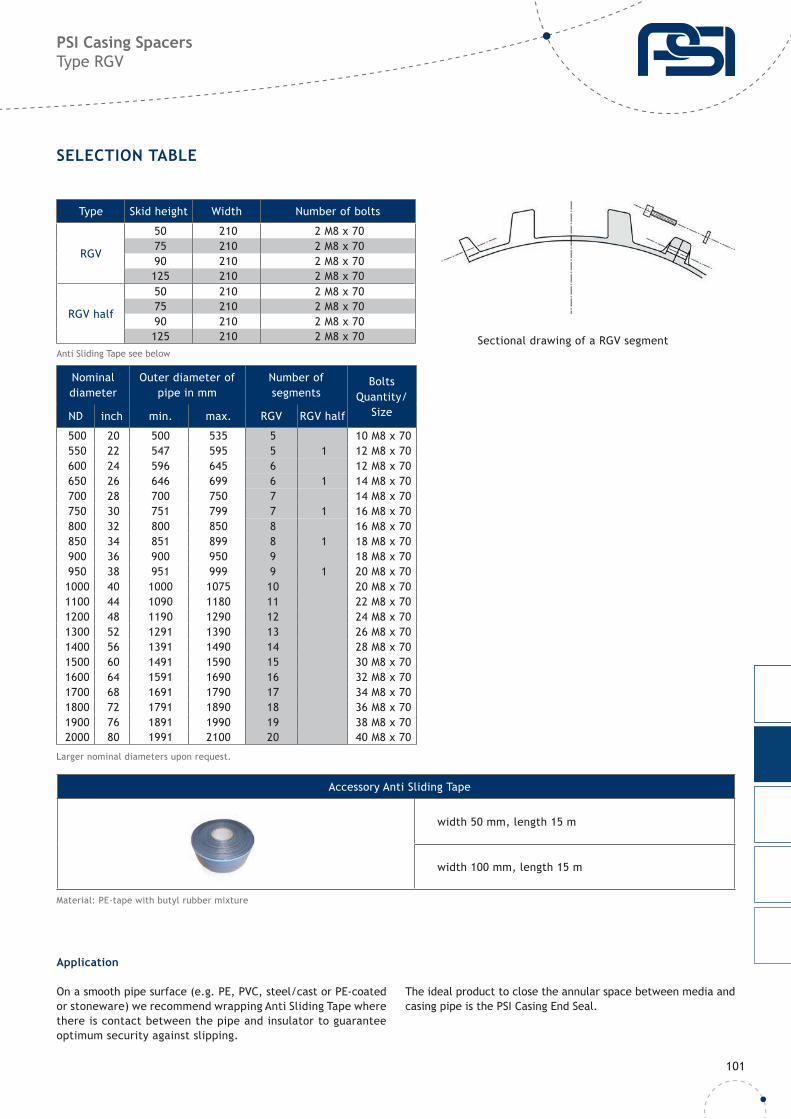
SELECTION TABLE
Type Skid height Width Number of bolts
RGV
50 210 2 M8 x 7075 210 2 M8 x 7090 210 2 M8 x 70125 210 2 M8 x 70
RGV half
50 210 2 M8 x 7075 210 2 M8 x 7090 210 2 M8 x 70125 210 2 M8 x 70
Nominal diameter
Outer diameter of pipe in mm
Number ofsegments
BoltsQuantity/
SizeND inch min. max. RGV RGV half
500 20 500 535 5 10 M8 x 70550 22 547 595 5 1 12 M8 x 70600 24 596 645 6 12 M8 x 70650 26 646 699 6 1 14 M8 x 70700 28 700 750 7 14 M8 x 70750 30 751 799 7 1 16 M8 x 70800 32 800 850 8 16 M8 x 70850 34 851 899 8 1 18 M8 x 70900 36 900 950 9 18 M8 x 70950 38 951 999 9 1 20 M8 x 701000 40 1000 1075 10 20 M8 x 701100 44 1090 1180 11 22 M8 x 701200 48 1190 1290 12 24 M8 x 701300 52 1291 1390 13 26 M8 x 701400 56 1391 1490 14 28 M8 x 701500 60 1491 1590 15 30 M8 x 701600 64 1591 1690 16 32 M8 x 701700 68 1691 1790 17 34 M8 x 701800 72 1791 1890 18 36 M8 x 701900 76 1891 1990 19 38 M8 x 702000 80 1991 2100 20 40 M8 x 70
Material: PE-tape with butyl rubber mixture
Larger nominal diameters upon request.
Accessory Anti Sliding Tape
width 50 mm, length 15 m
width 100 mm, length 15 m
Sectional drawing of a RGV segmentAnti Sliding Tape see below
Application
On a smooth pipe surface (e.g. PE, PVC, steel/cast or PE-coated or stoneware) we recommend wrapping Anti Sliding Tape where there is contact between the pipe and insulator to guarantee optimum security against slipping.
The ideal product to close the annular space between media and casing pipe is the PSI Casing End Seal.
102
PSI Casing SpacersType GKO-gl, GKO-gs and GKO-gs H
GENERAL INFORMATION
Subject to technical changes
More content can be found on www.psi-products.com
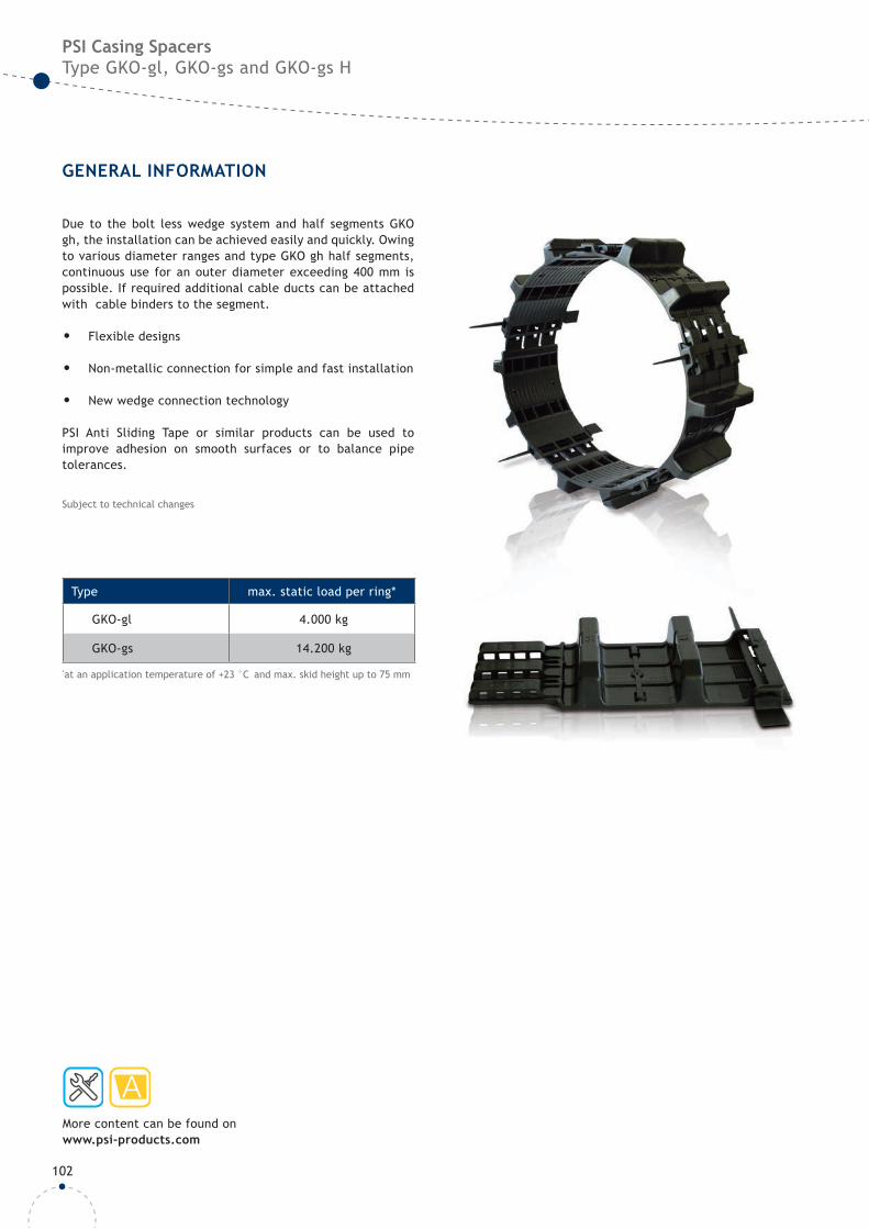
Due to the bolt less wedge system and half segments GKO gh, the installation can be achieved easily and quickly. Owing to various diameter ranges and type GKO gh half segments, continuous use for an outer diameter exceeding 400 mm is possible. If required additional cable ducts can be attached with cable binders to the segment.
• Flexible designs
• Non-metallic connection for simple and fast installation
• New wedge connection technology
PSI Anti Sliding Tape or similar products can be used to improve adhesion on smooth surfaces or to balance pipe tolerances.
Type max. static load per ring*
GKO-gl 4.000 kg
GKO-gs 14.200 kg
*at an application temperature of +23 °C and max. skid height up to 75 mm
103
PSI Casing SpacersType GKO-gl, GKO-gs and GKO-gs H
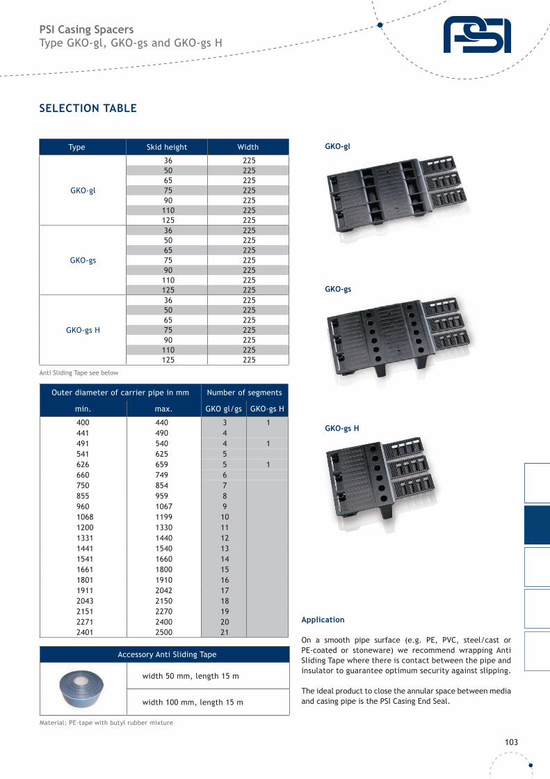
SELECTION TABLE
Type Skid height Width
GKO-gl
36 22550 22565 22575 22590 225110 225125 225
GKO-gs
36 22550 22565 22575 22590 225110 225125 225
GKO-gs H
36 22550 22565 22575 22590 225110 225125 225
Outer diameter of carrier pipe in mm Number of segments
min. max. GKO gl/gs GKO-gs H
400 440 3 1441 490 4491 540 4 1541 625 5626 659 5 1660 749 6750 854 7855 959 8960 1067 91068 1199 101200 1330 111331 1440 121441 1540 131541 1660 141661 1800 151801 1910 161911 2042 172043 2150 182151 2270 192271 2400 202401 2500 21
GKO-gl
GKO-gs
GKO-gs H
Accessory Anti Sliding Tape
width 50 mm, length 15 m
width 100 mm, length 15 m
Material: PE-tape with butyl rubber mixture
Anti Sliding Tape see below
Application
On a smooth pipe surface (e.g. PE, PVC, steel/cast or PE-coated or stoneware) we recommend wrapping Anti Sliding Tape where there is contact between the pipe and insulator to guarantee optimum security against slipping.
The ideal product to close the annular space between media and casing pipe is the PSI Casing End Seal.
104
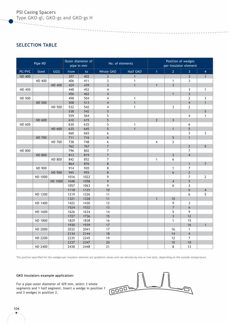
1 2 3 4
Pipe ND Outer diameter of
pipe in mmNo. of elements
Position of wedgesper Insulator element
PE/PVC Steel GGG from to Whole GKO Half GKO 1 2 3 4ND 400 397 402 3 1 3 1
ND 400 406 411 3 1 1 3ND 400 429 439 3 1 1 3
ND 450 448 452 4 3 1456 462 4 1 3
ND 500 498 504 4 1 2 3ND 500 508 513 4 1 4 1
ND 500 532 542 4 1 3 2538 542 5 5559 564 5 4 1
ND 600 610 615 5 2 3ND 600 630 635 5 1 6
ND 600 635 645 5 1 1 5660 665 6 3 3
ND 700 711 716 6 5 1ND 700 738 748 6 4 2
762 767 7 2 5ND 800 796 802 7 7
ND 800 813 819 7 3 4ND 800 842 852 7 1 6
864 870 8 1 7ND 900 914 920 8 1 7
ND 900 945 955 8 6 2ND 1000 1016 1022 9 7 2
ND 1000 1048 1058 9 4 51057 1063 9 6 31118 1125 10 6 4
ND 1200 1219 1226 11 6 51321 1328 11 1 10
ND 1400 1422 1430 12 9 31524 1532 13 7 6
ND 1600 1626 1634 14 5 91727 1736 15 3 12
ND 1800 1829 1838 16 1 151930 1939 17 16 1
ND 2000 2032 2041 17 16 12134 2144 18 14 4
ND 2200 2235 2245 19 12 72337 2347 20 10 10
ND 2400 2438 2448 21 8 13
PSI Casing SpacersType GKO-gl, GKO-gs and GKO-gs H
SELECTION TABLE
GKO Insulators example application:
For a pipe outer diameter of 429 mm, select 3 whole segments and 1 half segment. Insert a wedge in position 1 and 3 wedges in position 2.
The position specifi ed for the wedges per insulator element are guideline values and can deviate by one or two slots, depending on the outside temperature.
PSI Products GmbHUlrichstrasse 2572116 Mössingen / Germany
Phone: 0 049 (0)7473 3781 0Fax: 0 049 (0)7473 3781 35E-Mail: [email protected]
www.psi-products.com© PSI Products GmbH, 08 I 2019