Embed Size (px)
Citation preview

J. Electroanal. Chem., 165 (1984) 9-20 9 Elsevier Sequoia S.A., Lausanne Printed in The Netherlands
P S E U D O REACTION RATE IN THE AC RESPONSE OF AN ELECTROLYTIC CELL
J. ROSS MACDONALD and CARMIE A. HULL
Department of Pt~vsics and AstronomY, Unwersitv of North Carohna, Chapel Hill NC 27514 (U.S.A.)
(Received 29th August 1983)
ABSTRACT
When theoretical impedance-frequency "data" calculated from an exact small-signal ac solution of the transport equations for an unsupported intrinsic-conduction situation are fitted to an appropriate equivalent circuit using nonlinear complex least squares, one finds that a non-zero apparent charge transfer resistance is necessary for a good fit even when charges of one sign are taken completely blocked at the electrodes and those of opposite sign are taken as completely unblocked. Normally, one would expect no reaction resistance under these conditions. This effect only occurs when positive and negative charges have different mobilities and may be ascribed to ambipolar drag of one set of charges on the other set. Here we demonstrate the effect and derive approximate relations to be used in data analysis which should allow an accurate estimate of the true reaction rate to be obtained when it is not too large. The practical limit to the maximum reaction rate which can be derived from experimental impedance data for the present situation is shown to depend on both a diffusion coefficient and the Debye length.
INTRODUCTION
We consider here the small-signal ac response of a system comprised of two identical plane parallel metallic electrodes separated by a distance l and containing material with a dielectric constant c, taken frequency independent over the range of frequencies of interest. It is assumed that the material between the electrodes contains mobile uni-univalent positive and negative charges, with mobilities at the temperature of measurement of/£p and/~n, respectively. Thus we are concerned with an unsupported situation applying to either solid or liquid electrolytes. We assume that the mobile charges arise from the dissociation of neutral centers (e.g. a salt in liquids; the basic material in aliovalent single crystals, yielding Schottky or Frenkel defects; or even electrons and holes in electronic semiconductors). We thus consider an unbiased intrinsic conduction situation and further assume that dissociated pairs recombine bimolecularly [1,2].
The exact small-signal solution of the above problem, with [in fact] extrinsic as well as intrinsic conduction and ge~ _ration-recombination, has been given but is very complicated in the general case [1]. Here we initially consider the often encountered situation where charges of one sign, say the positive ones, are com-
0022-0728/84/$03.00 © 1984 Elsevier Sequoia S.A.

10
pletely blocked at the electrode, and the negative ones are completely unblocked, show ohmic behavior, and may thus be considered to react at the electrodes exceedingly rapidly (infinite reaction rate, k , ) . With the signs reversed this is a common parent-ion electrode situation for ionic conductions. (Although the sign choice is arbitrary, we use the present selection of signs and reaction rates for agreement with previously published work embodying this selection.)
Let the electrode reaction rates for positive and negative charge carriers be denoted kp and kn, where here we shall always choose kp = 0 and will initially take k n = o0. Let us normalize all rates so that pj =- ( l / 2 ) ( k / / D j ) , where Dj is the diffusion coefficient of the j t h type of charges. Thus 0 n - ( 1 / 2 ) ( k n / D n ) " Next, denote the mobility ratio as ~m ~ ~n/~p' Clearly as/~n ~ OO, since there is no blocking assumed for negative carriers, the impedance of the system must approach zero for all frequencies, an uninteresting condition. We are interested here in the opposite situation, that where t~, _< ~p and q?'rn becomes small.
We need to define a few more parameters. Let the geometrical capacitance of the system be denoted by C 1 - E / 4 ~ r l , where all extensive quantities will be given for unit electrode area. Further, let the high-frequency limiting resistance be denoted R 1 =- [(eCo//l)(l~p + ~n)] -1, where c o is the common undisturbed bulk value of the concentration of the positive and negative charge carriers. Then the dielectric relaxation time ~-i~ is just R1C 1. Next, we need the quantities A and ~, where A is a measure of the intrinsic dissociation ratio (small when A << 1 and approaching full dissociation for A >> 1); and ~ - ~-I/~D, where ~'~ is the intrinsic recombination relaxation time [1]. We shall be entirely concerned with ~ >> 1, so we are not dealing with relaxation semiconductor behavior [3]. Finally, define M =- l / 2 L D, the number of two-mobile Debye lengths in half of the cell. Here L D - [~kT/87re2co] 1/2, where k is Boltzmann's constant, T is the thermodynamic temperature, and e is the proton charge.
For increased generality, it is useful to deal with normalized quantities. Let us therefore normalize all resistances and impedances with R~ and all capacitances with C1; then R N -- R / R 1, CN -- C / C 1 and the normalized frequency is ~ - w~- D - w R 1 C 1.
For most experimental impedance measurements, even at the maximum measured frequency, ~2 < 1.
The system and conduction situation described above is a common one yet it has not been fully analyzed so far even though its exact solution exists [1]. Usually, impedance or admittance data are compared with the predictions of a plausible equivalent circuit by graphical or least squares methods [4-6] in order to determine values of the equivalent circuit parameters. Although it is very desirable to interpret these first-level parameters in terms of more basic and microscopic material/elec- trode characterizing parameters [1,7,8], this is not always done. As we shall show, in the present situation there is an appreciable chance, for fast electrode reactions, that the most natural microscopic interpretation will be erroneous, leading to an incorrect estimate of k n unless the present analysis is employed.
As discussed elsewhere in detail [5], we believe that the most objective way to obtain equivalent circuit parameter estimates from experimental impedance or
11
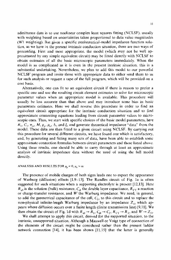
admittance data is to use nonlinear complex least squares fitting (NCLSF), usually with weighting based on uncertainties taken proportional to data value magnitudes (W1 weighting). But given a specific mathematical-model impedance function solu- tion, as we have in the present intrinsic conduction situation, there are two ways of proceeding. First and most appropriate, the model (which may not be well ap- proximated by any simple equivalent circuit) may be fitted directly with NCLSF to obtain estimates of all the basic microscopic parameters immediately. When the model is as complicated as it is even in the present intrinsic situation, this is a substantial undertaking. Nevertheless, we plan to add this model to our powerful NCLSF program and invite those with appropriate data to either send them to us for such analysis or request a tape of the full program, which will be provided on a cost basis.
Alternatively, one can fit to an equivalent circuit if there is reason to prefer a specific one and use the resulting circuit element estimates to solve for microscopic parameter values when an appropriate model is available. This procedure will usually be less accurate than that above and may introduce some bias in basic parameters estimates. Here we shall reverse this procedure in order to find an equivalent circuit appropriate for the intrinsic conduction situation and to find approximate connecting equations leading from circuit parameter values to micro- scopic ones. Thus, we start with specific choices of the basic model parameters, here R 1, C1, ~r m, M, pp, /On, A, and ~, and generate theoretical impedance "data" from the model. These d~ta are then fitted to a given circuit using NCLSF. By carrying out this procedure for several different circuits, we have found one which is satisfactory, and, by generating and fitting many sets of data, have been able to establish some approximate connection formulas between circuit parameters and those listed above. Using these results, one should be able to carry through at least an approximate analysis of intrinsic impedance data without the need of using the full model directly.
A N A L Y S I S A N D R E S U L T S F O R pp = 0, on = o¢
The presence of mobile charges of both signs leads one to expect the appearance of Warburg (diffusion) effects [1,9-13]. The Randles circuit of Fig. la is often suggested for such situations when a supporting electrolyte is present [12,13]. Here Rs0 is the solution (bulk) resistance, Cd~ the double layer capacitance, R c . r a reaction or charge-transfer resistance, and W the Warburg impedance. We need, in general, to add the geometrical capacitance of the cell, C1, to this circuit and to replace the non-physical infinite-length Warburg impedance by an impedance Z D which ap- pears where diffusion occurs over a finite length (finite transmission line) [9,11]. We then obtain the circuit of Fig. ld with Rso ~ RI , Call ---, C 2, Rcv ~ R 2 , and W ~ Z D.
We shall attempt to apply this circuit, derived for the supported situation, to the intrinsic, unsupported situation. Although a Maxwell or Voigt type of connection of the elements of the circuit might be considered rather than the present ladder network connection [14], it has been shown [11,15] that the latter is generally

12
[ I I ,,! ~s0 ]
(o)
I c'
(b)
Fig. 1. Possible f i t t ing circui ts .
I Ic' 1
(c)
I t c,
0 C~, 0
preferable, at least in the unsupported situation. Expression for R~ and C~ have already been given. We do not initially have adequate expressions for R2N and C2N in the present case. An approximate analysis of the exact solution with (pp = 0 and O,, = ~ ) yielded, however, for the fully dissociated case [1], R2N = 0, as expected with an infinite reaction rate, and C2N near the ordinary normalized double layer capacitance expression, r - 1, where r -~ (M)ctnh ( M ). For ZDN we take the shorted transmission line result [11]
ZDy = ZDo N ( i ~H~ ) - , /2 t anh ( i~H~ ) , /z (1)
where ~H~ - ~oH 2, s o H N = H/"rlD/2. In the case of supported diffusion of charge of a single sign. H - l~ f D , where l is the diffusion length, here the effective electrode separation, and D is the diffusion coefficient of the diffusing quantity. To interpret the results of fitting intrinsic two-mobile data to the circuit of Fig. ld in terms of microscopic parameters, we need expressions for CzN, R 2y, ZDOY, and H N.
In order to simplify our approach as much as possible, we shall generate exact intrinsic data with R 1 and Cl each taken unity. This leads to no significant loss of generality. Although numerical results for normalized and unnormalized quantities will then be the same, we must maintain the distinction in our formulas in order to allow one to pass properly from normalized to unnormalized expressions. Let Z y -- Z'y - iZ'~ denote the total normalized impedance and YN -- ZN 1 -- Y~ + iY~, the total normalized admittance. Although the full-dissociation data generated seemed to lead to the standard finite-length Warburg shape [9,11,16,17] when Z~

13
was plotted in the complex plane for given ~m, appreciable shape dependence on qT m was observed when YN results were plotted in the complex plane. Here the superscript asterisk indicates complex conjugation. Figure 2 illustrates the behavior obtained for a variety of % values. These curves, produced automatically on a plotter, each involved as many as 100 points. The top of the spike of infinite height at Y~ = 1 has been eliminated. Figure 2 shows a surprising variety of shapes with only one of them (~r m --10 2) looking at all like the quarter circle one sometimes expects [17] with Warburg processes present. Although the Z~ curves increase in size as ~r m decreases, they do not change their shape like the YN ones do. Clearly as ~ r --* 0, the YN curve approaches a semicircle, a result consistent with the Fig. ld circuit when Z D = or.
We next tried fitting theoretical "data" calculated for a wide range of 7r m values to the circuits of Fig. ]b, c, and d using W1 weighting. Results for the standard deviation of overall fit, of, are shown in Fig. 3. All circuits are adequate for ~r m > 10-1, but clearly only that of Fig. ld is appropriate over the entire ~ range investigated. The exact solution [1] shows that in the ~m ~ ] case, where appreciable simplification is possible, the Fig. lc circuit should be appropriate with CZN ------ r -- 1 and R 2N = 0. In fact, we found it yielded virtually a perfect fit for 71" m = 1. The fitting values of ZDO N and H N obtained with the input values M = ] 0 4, and A and ~ both infinite, were 1 and 10 4, respectively.
Let us continue to restrict attention to the fully dissociated case. Results of much fitting of the Fig. ld circuit were analyzed, compared with the approximate results of
• 5 5 -
,5(]-
• 4 5 -
.40-
u
YN .30-
.25-
.20-
• 1 5 -
• 10"
~m : I 0 -6 / , / I
, /
f
/ / / . /
. 05 -
.00
/ /
/ / / i . ~ t 1- - - - - -
/ , , ~
11 / , ,~ , /"
r / / " t i " ,, I0
I I I I .o ,1 ,2 .3 .4
(gp_- 0 ~ ~ . ~ n = ~ o
\
\ \ \
16s \ , \ \ \
-~.~. 10-2 - \ \ \ i " % , t\l
/ I
I I I I I / • 5 .e .7 .B .9 1.0
#
YN
Fig. 2. Admittance plane plots for the normalized admittance, YN =- R1Y, for various values of the mobility ratio ~r m -= /%/ / tp .
14
,20-
.16- b
.12~ , \
• \ \Circuit l-c
.08- \
Circuit I - d - - x -
.oo I I I I - - J - - I I T I T I q7 I -6.0 -5.0 -4.0 -3.0 -2.0 - I ,0 .0 1.0
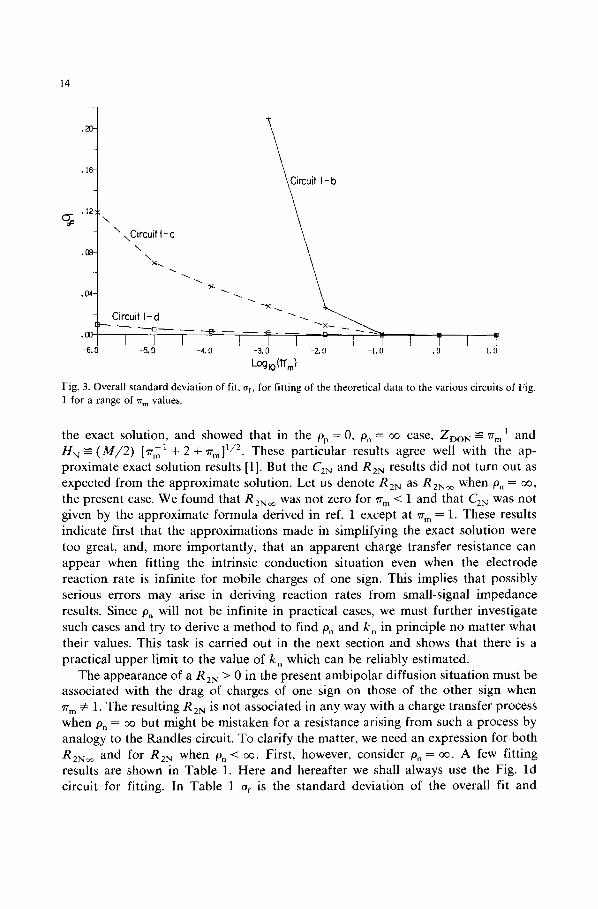
LoglO(1T m) Fig. 3. Overall standard deviation of fit, af, for fitting of the theoretical data to the various circuits of Fig. 1 for a range of 7r m values.
the exact solution, and showed that in the tap = 0, p, = oo c a s e , ZDO N ~-- 71"m 1 and H N -- ( M / 2 ) [~r£1 + 2 + ~rm] 1/2. These par t icu la r results agree well with the ap- p rox ima te exact solut ion results [1]. But the C2N and R2N results d id not turn out as expected f rom the app rox ima te solution. Let us denote R2N as R2yoo when p. = ~ , the present case. We found that R2yoo was not zero for ~r m < 1 and that C2N was not given by the app rox ima te formula derived in ref. 1 except at ~r m = 1. These results indicate first that the approx ima t ions made in s impl i fying the exact solut ion were too great, and, more impor tan t ly , that an appa ren t charge transfer resis tance can appea r when f i t t ing the intr insic conduc t ion s i tuat ion even when the e lec t rode reac t ion ra te is inf ini te for mobi le charges of one sign. This implies that poss ib ly serious errors m a y arise in der iving react ion rates f rom small-s ignal impedance results. Since On will not be infini te in prac t ica l cases, we must fur ther invest igate such cases and try to derive a method to f ind p, and k n in pr incip le no mat te r what their values. This task is carr ied out in the next sect ion and shows that there is a prac t ica l upper l imit to the value of k , which can be re l iably est imated.
The appea rance of a R 2N > 0 in the present amb ipo l a r diffusion s i tuat ion must be associa ted with the drag of charges of one sign on those of the other sign when ~r m 4= 1. The result ing R2N is not associa ted in any way with a charge t ransfer process when Pn = oo but might be mis taken for a resistance arising f rom such a process by ana logy to the Randles circuit. To clar ify the mat ter , we need an expression for bo th RzNoo and for R2N when p, < oo. First , however, consider p, = oo. A few fi t t ing results are shown in Table 1. Here and hereaf ter we shall a lways use the Fig. l d circui t for fitting. In Table 1 of is the s t andard devia t ion of the overall fit and
15
TABLE 1
Some fitting results for pp = 0, p, = oo, A = oo, ~ = oo, and M = 10 4. Results are shown in the form N/P , where N is a fitting estimate and P is its standard deviation in %
"~m ZDON HN C2N R 2N Of
10 0.1 1.739×10 -4 4.46×10⁵/0.31 0 9X10 6 1 1 104 9.999 X 10⁴ 0 10-13
10 -2 99.96/0.01 5.0497/0.01 6.77 ×10³/0.24 1.71X10 2/0.53 6 .9×10 4
10 6 9.97 X 10⁵/0.2 5.007/0.20 7.05 X 10³/0.20 2.09 × 10²/1.0 9.8 X 10- 3
numbers to the right of slashes are the estimated relative per cent standard deviations of the individual parameters. Even the ~r m = 10 6 fit is excellent. Similar results were obtained with other M values.
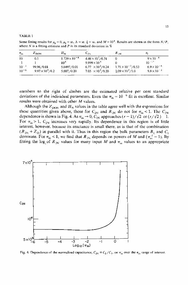
Although the ZDON and H N values in the table agree well with the expressions for these quantities given above, those for C2N and R2N do not for ~'m < 1. The C2N dependence is shown in Fig. 4. As ~m ~ 0, CZN approaches (r - 1 ) / ¢ 2 or ( r / v ~ ) - 1.
For %1 > 1, CZN increases very rapidly. Its dependence in this region is of little interest, however, because its reactance is small there, as is that of the combination (R2N + ZD) in parallel with it. Thus in this region the bulk parameters R 1 and C1 dominate. For ~r m < 1, we find that RZN depends on powers of M and (~r,~ - 1). By fitting the log.of R2N values for many input M and %1 values to an appropriate
7 x t O 4
CZN
i o ~ _
5xlO: -6
I I I [ I I
I I I I I I -.5 -4 -3 -2 -I 0
Log I0 ( 1'rml
Fig. 4. Dependence of the normalized capacitance, C2N ------ C2/C 1, on ~m over the ~r m range of interest.
16
function using multiple linear regression, we find
RZN ~ ------ 2.815 M-1 °s9 [ ~r~ 1 - 1] 1°19 (2)
with this result explaining 99.34% of the variation in the data. Nevertheless, this is not a very well-fitting result, and for many purposes, the result obtained from the data by requiring unity exponents,
R2Noo -~ 1.953 M- ' [~rm' - 1], (3)
will be sufficient. We find that when ~r m << 1, R2N~/ZI)oN =2/M. Thus, for sufficiently large M, R2N ~ will be negligible compared to Zt)ON. But even then, R2N ~ may play a significant role for those ~ > 0 frequency values where IZDI <<
ZDON. Since R2No~ will be small compared to ZI)ON for most M values of interest, it is
worthwhile to examine how well it can be determined for finite accuracy real data. We simulate this situation by truncating the theoretical data from its original 15 figures to four, three, or two figures. Note that truncation is more severe than rounding and introduces essentially random error. Results are presented in Table 2 where the "remaining figures" column shows the remaining number of figures in the data after any truncation. We see that even the 10% truncation-2 data results are not much degraded from untruncated values and that R2N ~ can still be well determined.
Now although the results of Fig. 2 show that an R 2 > 0 is needed to achieve an adequate data fit, Table 1 shows that the fit is still by no means perfect for 7r m < 1, but more serious, the failure of the data to lead to unity exponents in eqn. (2) suggests that the Fig. ld circuit is still not wholly adequate. We expect a quantity like R 2 ~ to be intensive, independent of l. But this is only the case for the M -1 dependence of eqn. (3). Then one finds that R2~ may be written in the form
R 2 o ¢ = 1 - 9 5 3 [ b t p - / x n ] 2 L D l ~p~-~#n J [ - - (4) ebt nO0 ]
entirely/-independent. But the partially extensive behavior of eqn. (2) is not the only
TABLE 2
Fitting results for Op = 0, Pn = oo, A = o0, M =102 (lines 1-4), M =104 (lines 5 and 6), and ~r m =10 -4, showing effects of data truncation
Remaining Zoo N H N C2N R 2N of figures
15 9760/0.14 4928/0.12 69.5/0.20 211/1.0 4 9757/0.14 4929/0.12 69.5/0.20 211/1.0 3 9746/0.16 4929/0.12 69.8/0.22 210/1.1 2 9656/0.43 4945/0.36 73.0/0.62 202/3.1
15 9990/0.05 5.002/0.04 6.98/0.16 1.92/0.78 2 9805/0.28 5.034/0.24 7.37/0.87 1.90/4.4
9.33×10 3 9.35x10 -3 1.01 × 10- 2 2.82x 10 2 3.5 xlO -3 1.60 × 10- 2
TABLE 3
Fitting results for pp = 0, On = ~ , M = 102, and ~m = 10 4, showing results of A and ~ variation
17
A ~ ZDO N H N C2N R 2N Of
102 104 9.76×10³/0.13 4.98 × 10³/0.11 69.7/0.19 207/0.93 8.61× 10 3 102 102 9.76 x 10³/0.14 4.98×10³/0.11 69.8/0.20 208/0.98 9.08× 10 -3 10 102 9.80 x 10³/0.10 5.40 x 10³/0.08 72.6/0.15 185/0.75 6.81 × 10 3
1 102 9.99 × 10³/0.48 8.55 × 10³/0.33 85.5/0.81 65.2/5.0 3.38 × 10- 2 10 ~ 102 1.00×10⁴/0.19 2.28 × 10⁴/0.15 70.3/1.6 1.45/22 1.49×10 -2 10- 2 102 9.71 x 10³/0.96 7.23 x 10⁴/0.78 77.9/3.0 6.98/6.2 7.51 x 10 -2
problem. The circuit of Fig. ld yields the following expression for the total normalized resistance RDN as ~2 ~ 0: RDN = 1 + RZN + ZDO. But the exact solution [1] leads to the exact result
RDN= (1 + ~rm')(1 + p n ' ) (5)
when pp = 0. When 0n = ~ as well, the two expressions for R DN require that R2N ~ + ZDO = ~rm ~. But we expect and find that ZDo --- ~rm 1. To the degree that this relation is exact, R 2N~ should disappear as ~2 --* 0, even though it plays an important role for non-zero ~2 values, particularly those larger than the ~2 value which leads to M a x [ I M ( Z g ) ] , about 2.53 (bM2) -1, where b - (qr m + 2 + ~rml)/4. Equation (5) shows that if experimental measurements could be extended to sufficiently low frequencies that Z D ~ ZDO----RDO, there would be no error in determining the reaction rate constant Pn or k. . But usually, data cannot be obtained at the very low frequencies Where zero-frequency results are adequately approximated. Then higher-frequency circuit fitting will generally yield a non-zero R 2 (even when Pn = ~ ) , and this resistance will need careful interpretation to avoid errors in reaction rate estimation.
So far we have set the generation-recombination parameters A and ~ infinite, appropriate for full dissociation. Comparison of the results presented in Tables 2 and 3 shows that reducing A and ~ to 100 makes very little difference in the results. But as A continues to decrease and there is less and less dissociation, we see that the overall fit deteriorates, H N increases and begins to approach A-1 behavior, and R 2N decreases until it is not well defined for A appreciably smaller than unity. It thus appears that n o R 2 is required in the circuit for strong recombination situations, but we shall not pursue the matter further here and shall take A and ~ infinite for the remaining work.
ANALYSIS A N D RESULTS FOR pp = 0, On ~< oo
Since the assumption Pn = OO is unduly restrictive, we have carried out numerous fittings with the Fig. ld circuit of exact intrinsic-model data for which On ~< 00. Although a proper expression for R2N in the present Pn < oo intrinsic case is not available from theory, earlier work leads to numerous expressions for the charge
18
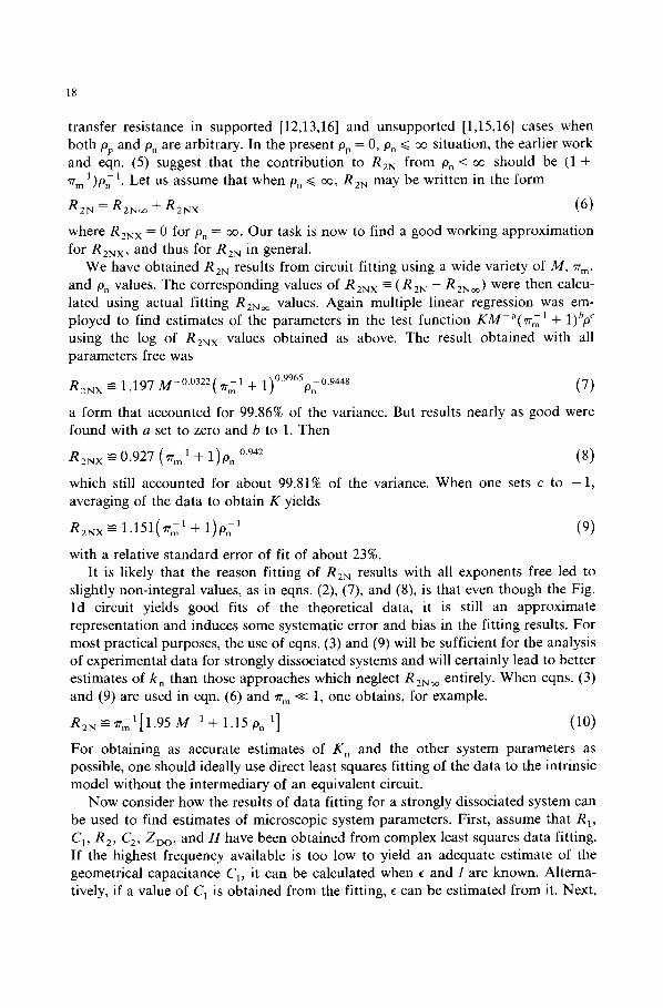
transfer resistance in supported [12,13,16] and unsupported [1,15,16] cases when both pp and 0n are arbitrary. In the present 0p = 0, & ~ ~ situation, the earlier work and eqn. (5) suggest that the contribution to R2N from Pn < ac should be (1 + ' a m 1)pnl. Let us assume that when 0n ~< oc, RZN may be written in the form
R2N = R2Nm q- R2NX (6)
where R2N x = 0 for & = m. Our task is now to find a good working approximation for R2N x, and thus for R2N in general.
We have obtained R2N results from circuit fitting using a wide variety of M, 7r m, and Pn values. The corresponding values of R2N x ~ (R2N -- R2N~) were then calcu- lated using actual fitting R2N m values. Again multiple linear regression was em- ployed to find estimates of the parameters in the test function KM-a(rrm 1 + 1)/'p C using the log of R2N x values obtained as above. The result obtained with all parameters free was
1~ 0"9965 0 9448 R2N x -- 1.197 M-°'°322('/rm I + 1) On " (7)
a form that accounted for 99.86% of the variance. But results nearly as good were found with a set to zero and b to 1. Then
R2Nx ~ 0.927 (~rml + 1)Pn °942 (8)
which still accounted for about 99.81% of the variance. When one sets c to - 1 , averaging of the data to obtain K yields
R2Nx =-- 1.151(~rm' + 1 ) 0 ; ' (9)
with a relative standard error of fit of about 23%. It is likely that the reason fitting of R2N results with all exponents free led to
slightly non-integral values, as in eqns. (2), (7), and (8), is that even though the Fig. ld circuit yields good fits of the theoretical data, it is still an approximate representation and induces some systematic error and bias in the fitting results. For most practical purposes, the use of eqns. (3) and (9) will be sufficient for the analysis of experimental data for strongly dissociated systems and will certainly lead to better estimates of k n than those approaches which neglect R2N ~ entirely. When eqns. (3) and (9) are used in eqn. (6) and rr m << 1, one obtains, for example,
R2N ------ ~r,; 1 [1.95 M ' + 1.15 O~ -1] (10)
For obtaining as accurate estimates of K n and the other system parameters as possible, one should ideally use direct least squares fitting of the data to the intrinsic model without the intermediary of an equivalent circuit.
Now consider how the results of data fitting for a strongly dissociated system can be used to find estimates of microscopic system parameters. First, assume that R~, C1, R2, C2, ZDO , and H have been obtained from complex least squares data fitting. If the highest frequency available is too low to yield an adequate estimate of the geometrical capacitance C 1, it can be calculated when c and l are known. Alterna- tively, if a value of C1 is obtained from the fitting, c can be estimated from it. Next,
19
form R2N , C2N , HN, and ZDON. We obtain an estimate of %, directly f rom ZDON--~rm 1. Then this value may be used in H N ~(M/2) [Trml + 2 + ~ m ] 1/2 to estimate M. This value of M should usually be preferable to that obtained from C2N --- 0.7 [ ( M ) c t n h ( M ) - 1] which seems to apply for ~r m < 0,1 (see Fig. 4), but the two values should certainly be comparable. Next, R2N ~ may be calculated using eqn. (2) or (3). Then RZN X --= R2N -- R2N ~ may be formed. Finally an estimate of On may be calculated using eqn. (7), (8), or (9).
Now from the estimate of M found above, one immediately obtains the Debye length L D. When c is known, it may be used to calculate an estimate of the bulk concentra t ion c 0. Then using the value of G 1 - R 1 ~ = ( e c o / l ) (1 + %11)/~n and the values of c o and ~r m already found, one obtains estimates of ~n and t%. For a uni -univa lent system, D i = ( k T / e ) t ~ i . Finally. k n may then be calculated from k n =-2D.pn / l . Thus assuming that l and the electrode area are known, one can calculate f rom RI, C 1, R,_, C 2, ZDO and H the full system characterization parame- ters L D, E, c o, #n, ~p, On, and k n.
Al though the above method of data analysis should be useful in most cases of interest, particularly those where k n is not too large, the accuracy of its k n estimate necessarily degrades as k n increases. There is therefore a practical limit to the size of k n or On which can be reliably estimated by the present approach, just as there is for other methods of determining k , . The problem arises f rom the subtraction RZN x =
R 2 N - R2N ~, where estimates of both members on the right will be uncertain and they approach each other as k n ---, oe. Let us make the reasonably conservative assumption that the min imum meaningful estimate of this difference, using good but not perfect data, is of the order of 0.5 R2N ~. Then the limiting relation R2N x --- 0.5 RZN~, yields, using the approximate results of eqns. (3) and (9), the following estimate of the maximum meaningful On:
P . . . . ~ M('B'm 1 -~- l)/(qTm 1 -- 1) (11)
which may usually be adequately approximated as p . . . . ~---M. In turn this result leads to
k . . . . . -~ D n / L D • (12)
For a D n of 10 -6 c m 2 / s and a L D of 10 -5 cm, k . . . . is then about 0.1 c m / s . Finally, it is of interest to examine w h a t sort of error would be made in the
estimate of k . if it were actually very large but this fact was not recognized and R 2 was believed to be R z x , arising from a non-infinite reaction rate, rather than the proper R 2 ~ . This would be the situation mentioned at the beginning of this work where the appearance of R 2 = R2~ from fitting when On is actually ~ is not taken into account. Let us use the approximate result, f rom Eq. (9), R2NX ------ (1 + ~m 1)l On 1. Then the above misinterpretation amounts to setting R z x = R 2 = R 2 ~ . From this equation, we immediately obtain
k n ~ 2On'°nl - 2Onl (1 q-R2 Nqrml) - 2 k T / e 2 c o R 2 = ( 1 6 ~ r / E ) ( L D / R 2 ) (13)

20
F o r example , if c = 5, L D = 10 -5 cm, and R 2 = 100 ~2, one would er roneous ly ob ta in k n --- 10 - i t c m / s . Since react ion rates general ly fall in the range 10 - iv < k _< 0.1, this
is a relat ively slow rate, far different f rom the value k n _> 0.1 one should have
ob ta ined with the p rope r analysis.
ACKNOWLEDGEMENTS
We apprec ia te the helpful comment s of Dr. S.W. Kenkel . This work was sup- po r t ed in par t by the Univers i ty of N o r t h Caro l ina Research Council , the Johnson ' s W a x Fund , and the U.S. A r m y Research Office. We are most grateful for this
suppor t .
REFERENCES
1 J.R. Macdonald and D.R. Franceschetti, J. Chem. Phys., 68 (1978) 1614. 2 J.R. Macdonald, D.R. Franceschetti and R. Meaudre, J. Phys. C, 10 (1977) 1459. 3 H.J. Queisser, H.C. Casey, Jr. and W. van Roessbroeck, Phys. Rev. Lett., 26 (1971) 551. 4 J.R. Macdonald and J.A. Garber, J. Electrochem. Soc., 124 (1977) 1022. 5 J.R. Macdonald, J. Schoonman and A.P. Lehnen, J. Electroanal. Chem., 131 (1982) 77, 6 Y.-T. Tsai and D.H. Whitmore, Solid State Ionics, 7 (1982) 129. 7 D.R, Franceschetti, J. Schoonman and J.R. Macdonald, Solid State Ionics, 5 (1981) 617. 8 J.R. Macdonald, A. Hooper and A.P. Lehnen, Solid State Ionics, 6 (1982) 65. 9 J.R. Macdonald, J. Electroanal. Chem., 32 (1971) 317.
10 J.R. Macdonald, J. Electroanal. Chem., 53 (1974) 1. 11 D.R, Franceschetti and J.R. Macdonald, J. Electroanal. Chem., 101 (1979) 307. 12 J.E.B. Randles, Discuss. Faraday Soc. 1 (1947) 11. 13 R.D. Armstrong, M.F. Bell and A.A. Metcalfe in H.R. Thirsk (Senior Reporter), Electrochemistry,
Specialist Periodical Report, Vol. 6, The Chemical Society, London, 1978, p. 98. 14 J.R. Macdonald in M. Kleitz and J. Dupuy, (Eds.), Electrode Processes in Solid State Ionics, Reidel,
Dordrecht, 1976, pp. 149-180. 15 D.R, Franceschetti and J.R. Macdonald, J. Electroanal. Chem., 82 (1977) 271. 16 J.R. Macdonald, J. Chem. Phys., 61 (1974) 3977. 17 J.R. Macdonald in G.D. Mahan and W.L. Roth (Eds.), Superionic Conductors, Plenum Press, New
York, 1976, pp. 81-97.

![Pseudo Limits, Biadjoints, and Pseudo Algebras: Categorical ...arXiv:math/0408298v4 [math.CT] 18 Oct 2006 Pseudo Limits, Biadjoints, and Pseudo Algebras: Categorical Foundations of](https://img.pdfslide.us/doc/110x75/60a7a6d20b1ec1029337c248/pseudo-limits-biadjoints-and-pseudo-algebras-categorical-arxivmath0408298v4.jpg)