Embed Size (px)
Citation preview

© Oxford University Press 2007. All rights reserved.1
Wireless Medium Access Control and CDMA-based Communication
Lesson 09Pseudo Noise Codes

© Oxford University Press 2007. All rights reserved.2
Pseudo-noise (PN) code
• Autocorrelation characteristics• A code appearing random like noise but is
actually not random• Used to generate one or multiple
sequences• PN codes useful for soft handover

© Oxford University Press 2007. All rights reserved.3
Pseudo-noise (PN) code
• A second BTS added for the users on the edge of a cell and new PN code used in new cell for soft handover
• Edge signal quality improves and handover becomes robust in soft-handover

© Oxford University Press 2007. All rights reserved.4
Soft handover in CDMA
• Adjacent cells of a CDMA system use the same set of carrier and chipping frequencies but different codes
• When the cell changes, an offset is added to the pseudo-noise codes
• Each cell has distinct pseudo-noise code offsets

© Oxford University Press 2007. All rights reserved.5
Soft handover in CDMA
• Pseudo-noise code offset processing can be done easily
• Only the offset value changes in case of handover when the signal of one cell becomes weak
• The call is not dropped, as the offset can be changed by the BTS depending on which cell has stronger signal at the boundary of two adjacent cells

© Oxford University Press 2007. All rights reserved.6
GSM
• GSM systems have separate operating frequencies in adjacent cells
• This is required to avoid inter-cell interference
• At the edge of the cells, handover is performed
• Call drop occurs

© Oxford University Press 2007. All rights reserved.7
M-sequences (maximum length sequences) code
• Code generated by using m small length shift registers
• The feedback generates a large number of sets, each set having m sequences
• Example: a set of 15 registers (m = 15) can be used to generate a set of (215 – 1) sequences
• Application as scrambling code

© Oxford University Press 2007. All rights reserved.8
M-sequence PN codes
• Quadrature component─ the 90°-phase-shifted component
• In-phase PNI component─ the same phase component orthogonal to Quadrature component
• IS-95 cdmaOne quadrature and in-phase component code sequences PNQ and PNI
© Oxford University Press 2007. All rights reserved.9
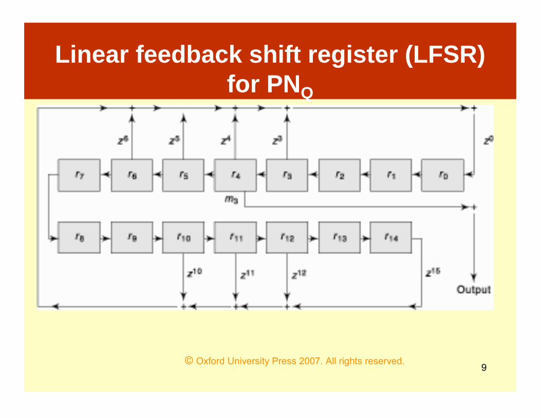
Linear feedback shift register (LFSR) for PNQ

© Oxford University Press 2007. All rights reserved.10
Initial State Vector
• An initial state vector has n bits in case of an n degree polynomial
• A set of n shift registers stores this vector on reset (at the start of the sequence generation)

© Oxford University Press 2007. All rights reserved.11
Initial State Vector for a a set of 15 registers for PNQ
• r14, …, r1, r0 for GQ─ initial vector is {000 1110 0011 1100}
• r11, r10, r9, r5, r4, r3, and r2 store 1s and rest store 0s at the start of a PN sequence
• Starting sequence should not be 0• At least one of the registers should store 1
and at least one of the binary numbers in the reset vector is 1

© Oxford University Press 2007. All rights reserved.12
Initial State Vector
• After n sequences, the same sequence as the first one is used to generate the next output sequence of bits after n .T, where T is the clock period
• Since generator polynomial GQ results in a different input to r0, the sequence changes after each interval of n .T

© Oxford University Press 2007. All rights reserved.13
Shift Parameter
• Positive integer• How much should be shifted after each
successive n sequences• If = 3, then it means each sequence starts
from register r3 in place of r0• Skipping r0, r1, and r2• If shift parameter = 0• Each sequence starts output from register
r0

© Oxford University Press 2007. All rights reserved.14
Mask Vector
• Specifies which register output is to be taken and is not masked and which set of registers output is masked and is not the input in next sequence
• 16 elements (m15, m14, m13, ..., m2, m1, and m0)

© Oxford University Press 2007. All rights reserved.15
Mask vector
• {000 0000 0001 0000} for PNQ defines shift parameter = 4 (because m4 = 1)
• The next sequence will start after n . Tfrom register r4 in place of r0

© Oxford University Press 2007. All rights reserved.16
IS-95 PNQ for generating multiple sequences
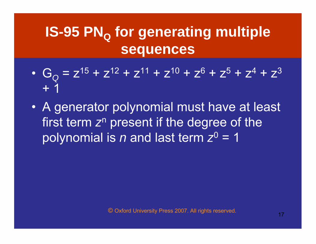
• GQ = z15 + z12 + z 11 + z10 + z6 + z5 + z4 + z3 + 1. A generator polynomial must have at least first term zn present if the degree of the polynomial is n and last term z0 = 1
© Oxford University Press 2007. All rights reserved.17
IS-95 PNQ for generating multiple sequences
• GQ = z15 + z12 + z11 + z10 + z6 + z5 + z4 + z3
+ 1• A generator polynomial must have at least
first term zn present if the degree of the polynomial is n and last term z0 = 1

© Oxford University Press 2007. All rights reserved.18
IS-95 PNQ for generating multiple sequences
• Using generator polynomial GQand mask vector (000 0000 0001 0000)
• An output bit is generated on each successive clock pulse
• The + sign shows an XOR operation

© Oxford University Press 2007. All rights reserved.19
GQ
• Maximum number of terms in an n degree polynomial is n + 1
• GQ─ 16 terms, but coefficients of 7 terms are 0s
• GQ = {1001 1100 0111 1001} or (15, 12, 11, 10, 6, 5, 4, 3, 0)
© Oxford University Press 2007. All rights reserved.20
PNI
• GI = z15 + z13 + z9 + z8 + z7 + z5 + 1

© Oxford University Press 2007. All rights reserved.21
Sequence Length
• Sequence length of PNQ is 215 –1 = 32767• Exactly the same sequences of bits are
outputted after each interval of (215 –1).T

© Oxford University Press 2007. All rights reserved.22
IS-95 Example
• Clock frequency to LFSR = 1.2288 MHz• Chipping rate is 1.2288 Mchip/s• The shift in the output occurs after each
chipping interval of 1/1.2288 Mchip.s –1 = 0.814 µs
• Spread factor = 64

© Oxford University Press 2007. All rights reserved.23
IS-95 Example
• Output sequence for each user symbol is divided into 64 chips, then the output appears every 0.814 µs
• Symbols and Sequences repetition at the rate = 1.2288 Mchips/s ÷ 64 = 19.2 kSymbol/s

© Oxford University Press 2007. All rights reserved.24
Gold Codes
• WCDMA uses Gold codes• Created from two M-sequence codes M1
and M2• M1 and M2 are added modulo 2

© Oxford University Press 2007. All rights reserved.25
Gold Codes
• M1 and M2 should be separate and distinct
• Different M1 and M2 are created by just using different starting registers
• Different starting registers can be set by setting the mask vector differently

© Oxford University Press 2007. All rights reserved.26
Summary
• IS-95 PN-Q and PN-I quadrature and in-phase components
• Pseudo noise codes• Linear feed Shift Register• Generator polynomial, Initial State
Vector and Mask register used for M-Sequence code
• WCDMA Gold Codes

© Oxford University Press 2007. All rights reserved.27
End of Lesson 09Pseudo Noise Codes


![Pseudo Limits, Biadjoints, and Pseudo Algebras: Categorical ...arXiv:math/0408298v4 [math.CT] 18 Oct 2006 Pseudo Limits, Biadjoints, and Pseudo Algebras: Categorical Foundations of](https://img.pdfslide.us/doc/110x75/60a7a6d20b1ec1029337c248/pseudo-limits-biadjoints-and-pseudo-algebras-categorical-arxivmath0408298v4.jpg)