Embed Size (px)
Citation preview
Pseudo-Elliptic Substrate Integrated Waveguide Filters with Higher-Order Mode Resonances
Mehdi Salehi1,2, Jens Bornemann1, and Esfandiar Mehrshahi2
1 Department of Electrical and Computer Engineering, University of Victoria, B.C., Canada 2 Department of Electrical and Computer Engineering, Shahid Beheshti University, G.C., Tehran, Iran
Abstract — Two substrate integrated waveguide (SIW)
pseudo-elliptic bandpass filters are presented that utilize higher-order mode cavities. In the first filter, two full-wave TE102 resonators and two fundamental TE101 resonators in a compact structure are properly coupled to generate two transmission zeros in a four-pole SIW filter. The coupling matrix of the structure with a centre frequency of 10 GHz and 200 MHz bandwidth is designed, and good agreement is achieved with simulations of two commercially available field solvers. In the second topology, by using symmetric inductive discontinuities and two rectangular SIW cavities, TE102 and TE301 modes are excited and generate two transmission zeros, one on each side of the passband. This dual-mode SIW filter with a centre frequency of 10 GHz and bandwidth of 300 MHz has been prototyped, and the measured data are in good agreement with results obtained from the coupling matrix and CST Microwave Studio.
Index Terms — Substrate integrated waveguide (SIW); transmission zero; bandpass filter; pseudo elliptic filter; dual-mode filter; coupling matrix.
I. INTRODUCTION
Technical specifications in wireless communication systems keep increasing the demand for high performance RF/microwave filters with compact size, sharp selectivity, high integration, and easy manufacturability. Although waveguide technology exhibits very low loss and provides high-Q resonators, it is bulky, heavy, and difficult to integrate with planar circuitry. On the other hand, although most passive and active circuits can be integrated in microstrip technology, the loss and quality factor as well as the cost of packaging and/or shielding are not acceptable for the fast-growing wireless communication markets.
Substrate integrated waveguide (SIW) is a promising technology that combines relatively high Q-factor and low insertion loss merits of traditional rectangular waveguides with the simplicity of planar fabrication and low-cost integration of microstrip technology [1-4].
Elliptic and quasi-elliptic bandpass filters with cross coupling are standard solutions to filtering specifications involving sharp selectivity, low in-band insertion loss, and high out of band rejection [5, 6]. However, both the unloaded Q-factor and the dimension of a SIW cavity decrease with increasing frequency. In order to obtain high-performance filters, higher-order mode cavities can be utilized [7-9].
Therefore, two SIW pseudo-elliptic bandpass filters using TEm0n resonances are presented in this paper. First, a four-pole SIW filter with two TE102 and two TE101 resonators is
used to create transmission zeros on either side of the passband.
Dual-mode resonators are widely used in filter design due to their ability to reduce the number of physical resonators and improve selectivity [10, 11]. Therefore, in the second design, we use dual-mode cavities resonating in TE301 and TE102 modes. All four resonances are properly coupled to generate a four-pole SIW filter with two transmission zeros close to the passband of the filter. The main advantage of the proposed structures, as compared to [8], is their symmetry with respect to the filter centre, which reduces the number of parameters in the final optimization process.
II. SYNTHESIS AND DESIGN OF FILTERS
The basic design of cross-coupled microwave filters in waveguide technology is well known, e.g. [12]. However, instead of extracting a coupling matrix for a folded prototype and applying matrix rotations [12], we arrive at the coupling matrix by optimization according to [13]. This has the advantage of enforcing the selected filter topology and the signs of the matrix elements. Once the coupling matrix is obtained, the individual coupling apertures are successively adapted using a mode-matching routine, e.g. [14].
A. SIW Filter in Single-Mode Topology
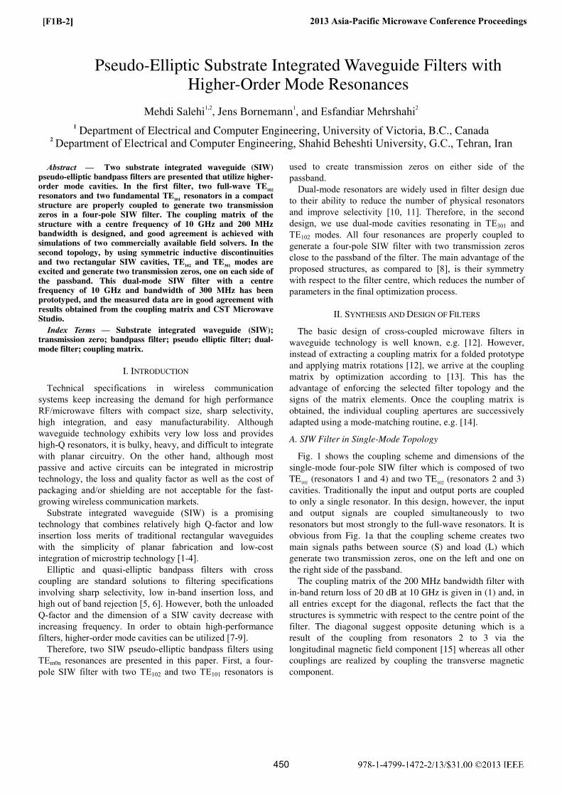
Fig. 1 shows the coupling scheme and dimensions of the single-mode four-pole SIW filter which is composed of two TE101 (resonators 1 and 4) and two TE102 (resonators 2 and 3) cavities. Traditionally the input and output ports are coupled to only a single resonator. In this design, however, the input and output signals are coupled simultaneously to two resonators but most strongly to the full-wave resonators. It is obvious from Fig. 1a that the coupling scheme creates two main signals paths between source (S) and load (L) which generate two transmission zeros, one on the left and one on the right side of the passband.
The coupling matrix of the 200 MHz bandwidth filter with in-band return loss of 20 dB at 10 GHz is given in (1) and, in all entries except for the diagonal, reflects the fact that the structures is symmetric with respect to the centre point of the filter. The diagonal suggest opposite detuning which is a result of the coupling from resonators 2 to 3 via the longitudinal magnetic field component [15] whereas all other couplings are realized by coupling the transverse magnetic component.
2013 Asia-Pacific Microwave Conference Proceedings
1
0.000 0.566 0.852 0.000 0.000 0.0000.566 1.149 0.000 -0.266 0.000 0.0000.852 0.000 -0.507 0.646 -0.266 0.0000.000 -0.266 0.646 0.507 0.000 0.8520.000 0.000 -0.
M =
266 0.000 -1.149 0.5660.000 0.000 0.000 0.852 0.566 0.000
⎡ ⎤⎢ ⎥⎢ ⎥⎢ ⎥⎢ ⎥⎢ ⎥⎢ ⎥⎢ ⎥⎢ ⎥⎣ ⎦
(1)
Fig. 1. Coupling scheme and configuration and dimensions in mm of the four-pole quasi-elliptic SIW filter with single-mode cavities. (Actual number of via holes according to inset of Fig. 2).
After determining the initial aperture and cavity dimensions, the filter dimensions are fine-optimizing for 10 GHz midband frequency, 200 MHz bandwidth, and 20 dB return loss. To speed up optimization, the circuit is first optimized in rectangular waveguide technology using the μWaveWizard. Then all square walls in the middle of the filter with the fixed width of dsquare=0.85 mm are replaced by circular via holes with a periodic distance of S=1.5 mm and a radius of
( )1 1 2circle squarer d= + (1)
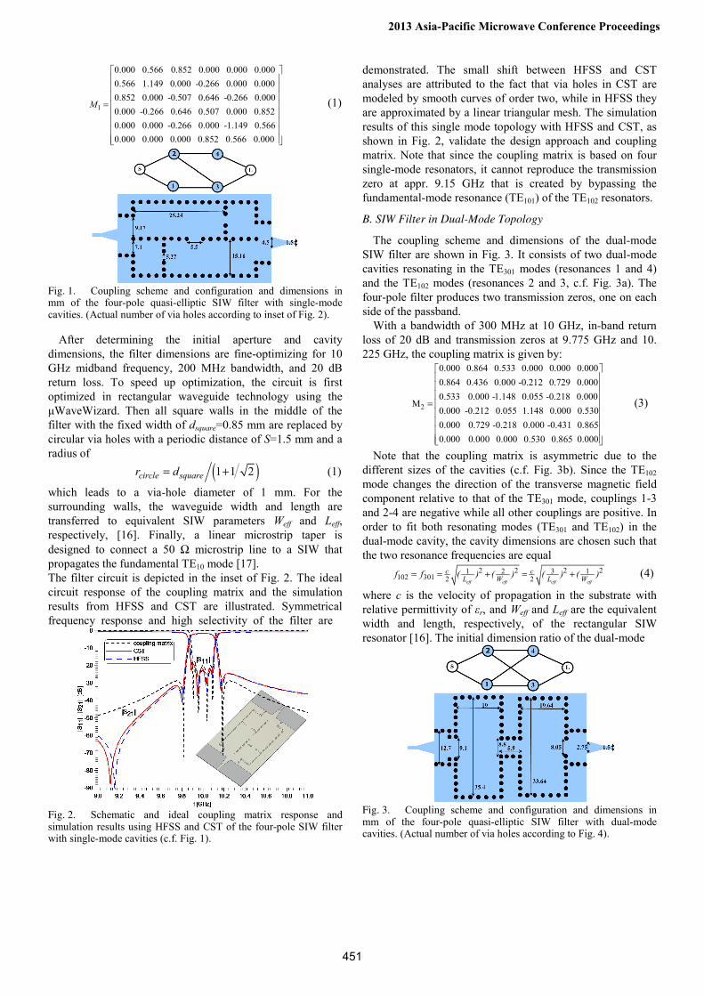
which leads to a via-hole diameter of 1 mm. For the surrounding walls, the waveguide width and length are transferred to equivalent SIW parameters Weff and Leff, respectively, [16]. Finally, a linear microstrip taper is designed to connect a 50 Ω microstrip line to a SIW that propagates the fundamental TE10 mode [17]. The filter circuit is depicted in the inset of Fig. 2. The ideal circuit response of the coupling matrix and the simulation results from HFSS and CST are illustrated. Symmetrical frequency response and high selectivity of the filter are
Fig. 2. Schematic and ideal coupling matrix response and simulation results using HFSS and CST of the four-pole SIW filter with single-mode cavities (c.f. Fig. 1).
demonstrated. The small shift between HFSS and CST analyses are attributed to the fact that via holes in CST are modeled by smooth curves of order two, while in HFSS they are approximated by a linear triangular mesh. The simulation results of this single mode topology with HFSS and CST, as shown in Fig. 2, validate the design approach and coupling matrix. Note that since the coupling matrix is based on four single-mode resonators, it cannot reproduce the transmission zero at appr. 9.15 GHz that is created by bypassing the fundamental-mode resonance (TE101) of the TE102 resonators.
B. SIW Filter in Dual-Mode Topology
The coupling scheme and dimensions of the dual-mode SIW filter are shown in Fig. 3. It consists of two dual-mode cavities resonating in the TE301 modes (resonances 1 and 4) and the TE102 modes (resonances 2 and 3, c.f. Fig. 3a). The four-pole filter produces two transmission zeros, one on each side of the passband.
With a bandwidth of 300 MHz at 10 GHz, in-band return loss of 20 dB and transmission zeros at 9.775 GHz and 10. 225 GHz, the coupling matrix is given by:
2
0.000 0.864 0.533 0.000 0.000 0.0000.864 0.436 0.000 -0.212 0.729 0.0000.533 0.000 -1.148 0.055 -0.218 0.000
M0.000 -0.212 0.055 1.148 0.000 0.5300.000 0.729 -0.218 0.000 -0.431 0.8650.000 0.000 0.000 0.530 0.865 0.000
⎡ ⎤⎢⎢⎢
= ⎢⎢⎢⎢⎢⎣
⎥⎥⎥⎥⎥⎥⎥⎥⎦
(3)
Note that the coupling matrix is asymmetric due to the different sizes of the cavities (c.f. Fig. 3b). Since the TE102 mode changes the direction of the transverse magnetic field component relative to that of the TE301 mode, couplings 1-3 and 2-4 are negative while all other couplings are positive. In order to fit both resonating modes (TE301 and TE102) in the dual-mode cavity, the cavity dimensions are chosen such that the two resonance frequencies are equal
2 2 2 231 2 1
102 301 2 2eff eff eff eff
c cL W L Wf f ( ) ( ) ( ) ( )= = + = + (4)
where c is the velocity of propagation in the substrate with relative permittivity of εr, and Weff and Leff are the equivalent width and length, respectively, of the rectangular SIW resonator [16]. The initial dimension ratio of the dual-mode
Fig. 3. Coupling scheme and configuration and dimensions in mm of the four-pole quasi-elliptic SIW filter with dual-mode cavities. (Actual number of via holes according to Fig. 4).
2013 Asia-Pacific Microwave Conference Proceedings
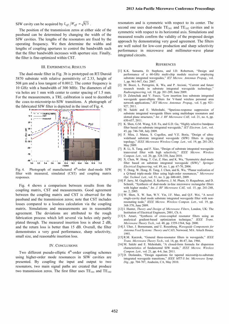
SIW cavity can be acquired by 8 3eff effL W = . The position of the transmission zeros at either side of the
passband can be determined by changing the width of the SIW cavities. The lengths of the resonators are fixed by the operating frequency. We then determine the widths and lengths of coupling apertures to control the bandwidth such that the filter bandwidth increases with aperture size. Finally, the filter is fine-optimized within CST.
III. EXPERIMENTAL RESULTS
The dual-mode filter in Fig. 3b is prototyped on RT/Duroid 5870 substrate with relative permittivity of 2.33, height of 508 μm and a loss tangent of 0.0012. The center frequency is 10 GHz with a bandwidth of 300 MHz. The diameters of all via holes are 1 mm with center to center spacing of 1.5 mm. For the measurements, a TRL calibration is used to deembed the coax-to-microstrip-to-SIW transitions. A photograph of the fabricated SIW filter is depicted in the inset of Fig. 4.
Fig. 4. Photograph of manufactured 4th-order dual-mode SIW filter with measured, simulated (CST) and coupling matrix responses.
Fig. 4 shows a comparison between results from the coupling matrix, CST and measurements. Good agreement between the coupling matrix and CST is observed for the passband and the transmission zeros; note that CST includes losses compared to a lossless calculation via the coupling matrix. Simulations and measurements are in reasonable agreement. The deviations are attributed to the rough fabrication process which left several via holes only partly plated through. The measured insertion loss is about 2 dB, and the return loss is better than 15 dB. Overall, the filter demonstrates a very good performance, sharp selectivity, small size, and reasonable insertion loss.
IV. CONCLUSIONS
Two different pseudo-elliptic 4th-order coupling schemes using higher-order mode resonances in SIW cavities are presented. By coupling the input and output to two resonators, two main signal paths are created that produce two transmission zeros. The first filter uses TE101 and TE102
resonators and is symmetric with respect to its center. The second one uses dual-mode TE301 and TE102 cavities and is symmetric with respect to its horizontal axis. Simulations and measured results confirm the validity of the proposed design approach by demonstrating very good agreement. The filters are well suited for low-cost production and sharp selectivity performance in microwave and millimeter-wave planar integrated circuits.
REFERENCES
[1] K.K. Samanta, D. Stephens, and I.D. Robertson, “Design and performance of a 60-GHz multi-chip module receiver employing substrate integrated waveguides,” IET Microw. Antennas Propag., vol. 1, pp. 961-967, Oct. 2007.
[2] M. Bozzi, L. Perregrini, K. Wu, and P. Arcioni, “Current and future research trends in substrate integrated waveguide technology,” Radioengineering, vol. 18, pp. 201-209, June 2009.
[3] D. Zelenchuk and V. Fusco, “Low insertion loss substrate integrated waveguide quasi-elliptic filters for V-band wireless personal area network applications,” IET Microw. Antennas Propag., vol. 5, pp. 921-927, 2011.
[4] M. Salehi and E. Mehrshahi, “Spurious-response suppression of substrate integrated waveguide filters using multishape resonators and slotted plane structures,” Int. J. RF Microwave CAE, vol. 21, no. 6, pp. 650-657, 2011.
[5] K. Shen, G.M. Wang, S.H. Fu, and G.D. Gu, “Highly selective bandpass filter based on substrate integrated waveguide,” IET Electron. Lett., vol. 45, pp. 746-748, July 2009.
[6] F. Mira, J. Mateu, S. Cogollos, and V.E. Boria, “Design of ultra-wideband substrate integrated waveguide (SIW) filters in zigzag topology,” IEEE Microwave Wireless Comp. Lett., vol. 19, pp. 281-283, May 2009.
[7] R. Li, X. Tang, and F. Xiao, “Design of substrate integrated waveguide transversal filter with high selectivity,” IEEE Microw. Wireless Compon. Lett., vol. 20, pp. 328-330, June 2010.
[8] X. Chen, W. Hong, T. Cui, Z. Hao, and K. Wu, “Symmetric dual-mode filter based on substrate integrated waveguide (SIW),” Springer Electrical Engineering, vol. 89, no. 1, pp. 67-70, 2006.
[9] Y. Dong, W. Hong, H. Tang, J. Chen, and K. Wu, “Planar realization of a Q-band triple-mode filter using high-order resonances,” Microwave Opt. Technol. Lett., vol. 51, no. 3, pp. 600-603, 2009 .
[10] P. Jarry, M. Guglielmi, E. Kerherve, J. M. Pham, O. Roquebrun, and D. Schmitt, “Synthesis of dual-mode in-line microwave rectangular filters with higher modes,” Int. J. RF Microwave CAE, vol. 15, pp. 241-248, no. 2, 2005.
[11] W. Shen, X. W. Sun, W.Y. Yin, J.F. Mao, and Q.F. Wei, “A novel single-cavity dual mode substrate integrated waveguide filter with non-resonating node,” IEEE Microw. Wireless Compon. Lett., vol. 19, pp. 368-370, June 2009.
[12] I. Hunter, Theory and Design of Microwave Filters, London, UK: The Institution of Electrical Engineers, 2001, Ch. 6.
[13] S. Amari, “Synthesis of cross-coupled resonator filters using an analysical gradient-based optimization technique,” IEEE Trans. Microwave Theory Tech., vol. 48, pp. 1559-1564, Sep. 2000.
[14] J. Uher, J. Bornemann, and U. Rosenberg, Waveguide Components for Antenna Feed Systems: Theory and CAD, Norwood, MA: Artech House, 1993.
[15] R.M. Kurzrok, “General three-resonator filters in waveguide,” IEEE Trans. Microwave Theory Tech., vol. 14, pp. 46-47, Jan. 1966.
[16] M. Salehi and E. Mehrshahi, “A closed-form formula for dispersion characteristics of fundamental SIW mode,” IEEE Microw. Wireless Compon. Lett., vol. 21, pp. 4-6, Jan. 2011.
[17] D. Deslandes, “Design equations for tapered microstrip-to-substrate integrated waveguide transitions,” IEEE MTT-S Int. Microwave Symp. Dig., pp. 704-707, Anaheim, CA, May 2010.
2013 Asia-Pacific Microwave Conference Proceedings


![[David S. Linthicum] Enterprise Application Integr(BookFi.org)](https://img.pdfslide.us/doc/110x75/5695d0861a28ab9b0292ce69/david-s-linthicum-enterprise-application-integrbookfiorg.jpg)