Embed Size (px)
Citation preview

Transaction A: Civil EngineeringVol. 17, No. 2, pp. 118{130c Sharif University of Technology, April 2010
Pseudo-Dynamic Active Earth PressureAnalysis of Inclined Retaining Walls
Using Horizontal Slices Method
A. Ghanbari1;� and M. Ahmadabadi1
Abstract. Retaining walls may be constructed with an inclination angle of less than 90�from thehorizontal axis. In the present study, using the horizontal slices method and limit equilibrium principles,in addition to assuming variation of the seismic coe�cient with height, a new formulation is proposedto calculate the active seismic pressure on retaining walls. The general arrangement of the proposedpseudo-dynamic formulation allows analysis of inclined or vertical retaining walls in frictional, cohesiveand cohesive-frictional soils. Results from the proposed method were compared with those of previousresearchers under similar conditions and showed a negligible di�erence. The horizontal slices method wasable to assess an inclined wall, determine the active earth pressure distribution at di�erent points alongthe wall height and consider the angle of failure wedge as a variable in the time domain. The �ndings showthat despite the accepted assumptions for conventional vertical walls the distribution of earth pressure onan inclined wall follows a non-linear pattern at each moment.
Keywords: Inclined retaining wall; Horizontal slices method; Pseudo-dynamic; Active earth pressure.
INTRODUCTION
Retaining walls are designed to withstand stressescaused by lateral earth pressure. The magnitude ofthis pressure is a function of the soil properties, thewall and the intensity of static and dynamic loads. Theinclination of a wall plays a major role in the reductionor increase in lateral earth pressure. An increase inthe inclination angle from the vertical state decreaseslateral earth pressure. Theories to calculate static andseismic pressures on retaining walls are usually onlyfor vertical conditions; applied pressure on inclinedretaining walls has rarely been a matter of concern.Figure 1 is an example of walls analyzed by previousresearchers where the wall does not incline toward thesoil mass, as opposed to the inclined retaining wall,which is the subject of the present study.
Inclined walls are subjected to less lateral earthpressure than vertical walls, even to the point whereat times the static earth pressure on an inclinedwall becomes zero. Inclined walls are employed in
1. Faculty of Engineering, Tarbiat Moallem University, Tehran,P.O. Box 15614, Iran.
*. Corresponding author. E-mail: [email protected]
Received 7 June 2009; received in revised form 10 December2009; accepted 18 January 2010
Figure 1. Deviation of failure wedge into horizontal slicesfor an inclined retaining wall.
embankment dams as lateral spillway walls, in coastalstructures, such as quay walls and in road buildingprojects as road protectors and on sideway slopes.
This paper �rst reviews theories of previous re-searchers and then proposes, using the horizontal slicesmethod, to calculate seismic pressure on inclined walls.In the proposed method, a variation of input-triggeringacceleration with time is considered and a pseudo-dynamic analytical solution is proposed for retainingwalls for the common range of periods.

Use of HSM in Analysis of Inclined Retaining Walls 119
Recent studies of geotechnical structures includeexperimental studies, numerical analysis and analyticalmodels. Analytical models include the homogenizedanalytical concept, limit analysis, limit equilibrium,the horizontal slices method and the characteristicsmethod [1-8].
Measuring earth pressure on retaining structuresfor granular soils in static conditions has usuallybeen performed using Rankine's [9] or Coulomb's [10]methods. However, Caquot and Kerisel [11],Sokolovskii [12], Lee and Herrington [13] and Hua andShen [14] have all advanced signi�cant procedures toestimate static lateral earth pressure in granular soils.
To calculate seismic pressure, one of the oldesttheories proposed was by Okabe [15] and Mononobeand Matsuo (M-O) [16]. This technique has beenpresented using Coulomb's theory [10] and assumingthe pseudo-static method to be valid for granularsoils. In the M-O method, equilibrium relations areformulated for a rigid wedge, assuming the seismiccoe�cient to be constant along the wall, and ignoringsoil cohesion seismic pressure on the wall is achieved.This method assumes stress distribution of the soil onthe wall to be linear.
The in uence of phase on the calculation ofpseudo-static earth pressure on a retaining wall andbehavior of quay walls in earthquakes was investigatedby Steedman and Zeng [17], Zeng and Steedman [18],Chang [19] and Choudhury et al. [5]. Cheng [19]suggested the rotation of axes as a solution for slipline equations to determine lateral earth pressure undergeneral conditions. Chang [19] also proposed a methodbased on pseudo-static analysis assumptions that con-tain all the limitations of the M-O method.
Recently, researchers have calculated pressure ap-plied to retaining walls using pseudo-static and pseudo-dynamic analysis. Choudhury and Nimbalkar [20,21]as well as Shekarian et al. [22] calculated the seismicpressure on retaining walls using a limit equilibriumtechnique. These studies were formulated for verticalwalls with cohesionless back�ll and under pseudo-staticconditions to address seismic acceleration. Nimbalkaret al. [23], Nimbalkar and Choudhury [6], Ahmad andChoudhury [24], Shekarian and Ghanbari [25] and Azadet al. [26] also studied seismic pressure under pseudo-dynamic conditions for vertical walls in granular soils.Finally, Ghosh [27] considered a method to calculatethe seismic pressure and angle of failure wedge forinclined walls with linear variations of acceleration byheight.
The present study used the horizontal slicesmethod and assumed pseudo-dynamic analysis to de-termine seismic stress distribution on retaining walls,the angle of failure wedge and the application point ofthe resultant force. The proposed method eliminatesthe limitations of previous techniques and ascertains
seismic pressure for an inclined wall with cohesive-frictional back�ll. Moreover, this method is able todetermine the non-linear stress distribution at di�erentdepths of an inclined wall.
HORIZONTAL SLICES METHOD
Originally, slices, especially in the conventional verticalslices method, were used to estimate slope stability.Shahgholi et al. [28] introduced one method to de-termine such slopes. The Horizontal Slices Method(HSM) was expanded upon by Nouri et al. [8,29] byaddressing the seismic acceleration at di�erent heightsof a structure. Azad et al. [26], Shekarian andGhanbari [25], Shekarian et al. [22] and Ahmadabadiand Ghanbari [7] employed HSM within the frameworkof pseudo-dynamic and pseudo-static methods to ascer-tain seismic active earth pressure on retaining walls.HSM is able to determine the distribution of seismicactive earth pressure and the application point of theresultant earth pressure.
To determine the active earth pressure of a re-taining wall with reinforced and unreinforced cohesive-frictional back�ll using HSM, the following assump-tions were made in the present study:
1. The application point of the vertical inter-slice forceis located at the surface-center of the stress distri-bution curve derived from the succeeding equations.
2. The failure surface is planar.
3. The method is limited to homogeneous masses.
4. The failure surface is assumed to pass through theheel of the wall.
5. The value of the shear force between horizontalslices is unequal (Hi 6= Hi�1).
6. The point where Ni acts on the slice base is locatedat the midpoint of that base.
7. The point where Pi acts is located at mid-height foreach slice.
PROPOSED METHOD
An arbitrary wall with height H and inclination slope �is shown in Figure 1, representing a general method forseismic pressure calculations on retaining walls. Theinterface of failure wedge and back�ll soil forms angle �with the horizontal axis. The failure wedge is dividedinto n slices with equal thicknesses of hi = H
n . Theapplied forces on the ith slice are shown in Figure 2.Distances in Figure 2 can be calculated using the

120 A. Ghanbari and M. Ahmadabadi
Figure 2. Equilibrium of forces on the ith slice.
following equations:
X1i =
nPj=1
hj
tan(B); (1)
X2i =
24 nXj=i
hj
35 tan(�); (2)
X1i+1 =
nPj=i+1
hj
tan(�); (3)
X3i =h(i)tan�
; (4)
X4i = h(i) tan �; (5)
XGi =x1i2
+x2i2� x3i
4� x4i
4: (6)
The weight of each slice can be determined as:
Wi = i�
(x1i � x2i � x3i)hi +(x4i + x3i)
2hi�:
(7)
To calculate the vertical stress acting between slices,the equation suggested by Segrestin [30] was employedin which the variations of vertical stress for eachhorizontal plane are addressed as:
vi = zi:�: (8)
In the above equation, Z is the depth of the hor-izontal plane from the top of the wall and � is acoe�cient smaller than unity and calculated by atangent-hyperbolic function for all points in the hor-izontal plane. Shekarian et al. [22] have described thiscalculation in detail. Notice that the application ofthis equation increases the precision of the analysisfor inclined walls in comparison with the �ndings ofresearchers who estimated the value of vertical stressas:
vi = zi:
The horizontal and vertical seismic forces on each sliceare Fh and Fv, respectively, which can be determinedas a fraction of the weight of the sliding wedge:
Fhi = ah(z; t):wi; (9)
Fvi = av(z; t):wi: (10)
Seismic active earth pressure can be obtained simi-lar to Steedman and Zeng [17] and Choudhury andNimbalkar [20] using the pseudo-dynamic method forback�ll soil. In the proposed method, it is assumedthat the base of the inclined wall is subject to bothhorizontal and vertical harmonic vibrations with am-plitudes of accelerations of ah(= khg) and av(= kvg),respectively, which begin at exactly the same time andwith no phase shift between them, thus, providingcritical design criteria. Variations of �h(z; t) and�v(z; t) are considered as sine functions in:
ah(z; t) = Khg�
sin!�t� H � z
vs
��; (11)
av(z; t) = Kvg�
sin!�t� H � z
vp
��; (12)
where t is time, Vs and Vp are velocity of shear andpressure waves in the soil, respectively, and Kh and Kvare the amplitudes of seismic acceleration coe�cientsin the horizontal and vertical directions, respectively.For most geotechnical materials, accepting the relationVpVs = 1:87 is appropriate [31]. In the pseudo-static con-dition, variations of horizontal and vertical coe�cientswith time are assumed to be constant. However, timehas an e�ect in the pseudo-dynamic condition, thus,causing horizontal and vertical coe�cient accelerationsto di�er depending on the period considered for theseismic load. Variations of the horizontal accelerationcoe�cient along the height of a wall for the twoconditions T = 0:2 and T = 0:8 are illustrated inFigure 3. As can be observed, at the moment oft and for each period of T , the seismic accelerationcoe�cient had a non-linear distribution along thewall.

Use of HSM in Analysis of Inclined Retaining Walls 121
Figure 3. Variations of horizontal pseudo-dynamicacceleration along the height of the wall for T = 0:2, 0.8sec.
Based on these assumptions, three equations forthe equilibrium of forces and moments and one for theshear strength of soil were formulated for each momentand each horizontal slice. The applied pressure oneach slice at di�erent points on a wall at each momentcan be determined by solving the equation set with 4nunknowns and 4n equations:X
Fx(t) = 0 �! Hi(t)�Hi+1(t)� Fhi(t)+ Si(t) cos�(t)�Ni(t) sin�(t)
+Pi(t) cos � cos �+Pi(t) sin � sin �=0; (13)XFy(t) = 0 �! �Vi(t) + Vi+(t) + Fvi(t)�Wi(t)
+ Si(t) sin�(t) +Ni(t) cos�(t)
�Pi(t)cos � sin �+Pi(t) sin � cos �=0; (14)
XMo(t) = 0 �! �Vi(t)XVi + Vi+1(t)XVi+1
+ (Fhi(t)�W (t)i)XGi
+�Fhi(t) +
Ni(t)sin�i(t)
� Pi(t) cos �cos �
��24 nXj=i+1
hj +hi2
35+Hi+1(t)nX
j=i+1
hj
�Hi(t)nXj=i
hj = 0; (15)
Si(t) = [Ni(t) tan�+ cfhi= sin(�)g]: (16)
Knowing the force of each slice, the non-linear pressuredistribution applied to the wall can be determined andthe resultant force calculated:
P (t) =nXi=1
Pi(t): (17)
The value of the angle of failure wedge (�) depends onthe applied stresses on the soil mass at each moment.To calculate �, the maximum active pressure on thewall is applied by the failure wedge and is written as:
@Pt(t)@�
= 0: (18)
The equations and unknowns of the formulation aresummarized in Table 1.
RESULTS
The proposed formulation can calculate the activepressure on the wall for each moment as well as for theangle of failure wedge. To this end, the model inclinedwall illustrated in Figure 4 was analyzed under a sineharmonic seismic load with period T . The propertiesof this wall are noted in Table 2.
Variations in the pressure and angle of the failurewedge over time were studied for the vertical retainingwall with granular back�ll. Since the pressure appliedto the wall is determined by limit equilibrium, itrepresents the active state for the soil and is indicatedby Pa(t). This pressure is a combination of the activestatic pressure and the excess dynamic pressure dueto seismic loading. Figure 5 shows the variations inthe active earth pressure and angle of failure wedgein the �rst second of loading for the model wall for aperiod of 0.2 sec. The magnitude of this pressure isrelated to the slope of the internal face of the wall. Itis proposed that the slope of the axis of the wall is equalto the slope of the internal face of the wall. The slope

122 A. Ghanbari and M. Ahmadabadi
Table 1. Equations and unknowns for horizontal slices method in the pseudo-dynamic state.
Unknowns Number Equations Number
Hi(t) nPFx(t) = 0 n
Ni(t) nPFy(t) = 0 n
Si(t) nPM0(t) = 0 n
Pi(t) n Si(t) = [Ni(t) tan�+ cfhi= sin(�(t))g] n
4n 4n
Table 2. Properties of the model wall for pseudo-dynamic analysis.
Series
Heightof Wall
(H)(m)
Cohesionof Soil
(c)(kN/m2)
InternalFrictionAngle
(�)(degrees)
Speci�cWeight of
Soil( )
(kN/m3)
Friction AngleBetween Soil
and Wall(�)
(degrees)
InclinationAngle of
Wall(�)
(degrees)
HorizontalSeismic
Coe�cient(Kh)
1 10.0 0.0 30 20.0 2�=3 0.0 0.2
2 10.0 20.0 30 20.0 2�=3 0.0 0.2
3 10.0 0.0 30 20.0 2�=3 0:0� 30:0 0:1� 0:4
4 10.0 0:0� 20:0 30� 40 20.0 2�=3 0:0� 30:0 0:0� 0:2
Figure 4. The model wall analyzed in the present research.
of the outer face of the wall only changes the axis ofthe wall and has no e�ect on the active earth pressuremagnitude.
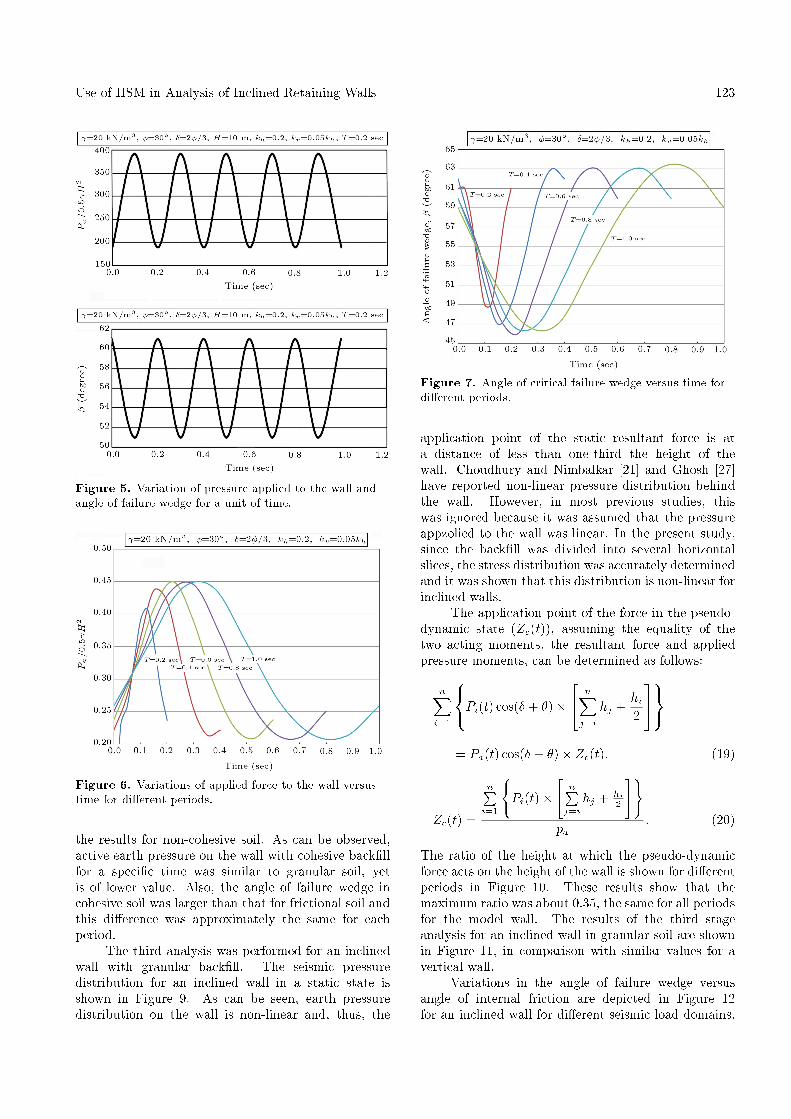
Figure 6 illustrates the variations of active pres-sure ratio versus time for the range of periods between0.2 and 1.0 sec. The maximum pressure ratio on thewall occurred between 0.1 to 0.3 sec from the beginningof loading and its value was between 0.4 and 0.45.Figure 7 shows the angle of failure wedge during thepseudo-dynamic loading at di�erent periods. The angleof failure wedge was between 43� and 62� and decreased
as the minimum period increased. The applied seismicload is a sine harmonic load with a period of T andits direction changes continuously. When the directionof the seismic load is left to right, the active earthpressure decreased. In this state, the behavior of thesoil changed from active to passive and the angle offailure wedge decreased.
The second stage of analysis was performed on avertical wall with cohesive-�ctional back�ll. Figure 8shows the variations in active earth pressure and theangle of failure wedge for 0.2 and 0.4 sec compared with
Use of HSM in Analysis of Inclined Retaining Walls 123
Figure 5. Variation of pressure applied to the wall andangle of failure wedge for a unit of time.
Figure 6. Variations of applied force to the wall versustime for di�erent periods.
the results for non-cohesive soil. As can be observed,active earth pressure on the wall with cohesive back�llfor a speci�c time was similar to granular soil, yetis of lower value. Also, the angle of failure wedge incohesive soil was larger than that for frictional soil andthis di�erence was approximately the same for eachperiod.
The third analysis was performed for an inclinedwall with granular back�ll. The seismic pressuredistribution for an inclined wall in a static state isshown in Figure 9. As can be seen, earth pressuredistribution on the wall is non-linear and, thus, the
Figure 7. Angle of critical failure wedge versus time fordi�erent periods.
application point of the static resultant force is ata distance of less than one-third the height of thewall. Choudhury and Nimbalkar [21] and Ghosh [27]have reported non-linear pressure distribution behindthe wall. However, in most previous studies, thiswas ignored because it was assumed that the pressureappzolied to the wall was linear. In the present study,since the back�ll was divided into several horizontalslices, the stress distribution was accurately determinedand it was shown that this distribution is non-linear forinclined walls.
The application point of the force in the pseudo-dynamic state (Zc(t)), assuming the equality of thetwo acting moments, the resultant force and appliedpressure moments, can be determined as follows:
nXi=1
8<:Pi(t) cos(� + �)�24 nXj=i
hj +hi2
359=;= Pa(t) cos(� + �)� Zc(t); (19)
Zc(t) =
nPi=1
(Pi(t)�
"nPj=i
hj + hi2
#)pa
: (20)
The ratio of the height at which the pseudo-dynamicforce acts on the height of the wall is shown for di�erentperiods in Figure 10. These results show that themaximum ratio was about 0.35, the same for all periodsfor the model wall. The results of the third stageanalysis for an inclined wall in granular soil are shownin Figure 11, in comparison with similar values for avertical wall.
Variations in the angle of failure wedge versusangle of internal friction are depicted in Figure 12for an inclined wall for di�erent seismic load domains.

124 A. Ghanbari and M. Ahmadabadi
Figure 8. Change in active earth pressure and angle of failure wedge in cohesive-frictional soils.
Figure 9. Stress distribution in the presence of a seismicload.
Variations of these angles by the inclination angle ofthe wall are shown in Figure 13. It can be observed inthese �gures that with an increase in the inclination ofthe wall and a decrease in the angle of internal friction,the angle of failure wedge decreased.
The fourth stage of analysis focused on an inclinedwall with cohesive-frictional back�ll, the most completecase for pseudo-static analysis where the limitations ofprevious methods are absent. Figure 14 shows the raw
Figure 10. Change in the application point of resultantforce versus time for di�erent periods.
active pressure distribution of the cohesive-frictionalback�ll on an inclined wall for slopes varying from zeroto 20�. An increase in the slope of the wall reduced thepressure applied to the wall, however, the distributionwas non-linear for all conditions. Variations of activepressure against the friction angle of the soil are shownin Figure 15.
The results show that when the friction angle ofsoil in the model wall was 40�, the applied pressure to

Use of HSM in Analysis of Inclined Retaining Walls 125
Figure 11. Analysis results for the third series for an inclined wall with granular back�ll.
the wall was negative and no pressure was generatedby the soil on the wall. This result is more accuratethan results obtained from previous methods in whichpressure distribution was assumed to be linear and,accordingly, the depth of the tensile cracks calculatedby the proposed method di�ers from those of othermethods.
Figure 16 shows the e�ect of the seismic loaddomain (Kh) on the pressure applied to the wall bythe cohesive-frictional back�ll. It is shown that, withan increase in the seismic load domain, pressure applied
to the wall increased, yet the non-linear distributionremained valid. Figure 17 shows the linear trend ofthe increase in the angle of failure wedge with anincrease in the internal friction angle of the soil foran inclined wall with cohesive-frictional back�ll fordi�erent cohesions.
COMPARSION OF METHODS
Several methods can be used to calculate seismicactive earth pressure on inclined walls, all of which

126 A. Ghanbari and M. Ahmadabadi
Figure 12. Change in the angle of failure wedge versusangle of internal friction for di�erent horizontal seismicpressure coe�cients c = 0 kN/m2, � = 2�=3, � = 20�,� = 0 and Kv = 0:5Kh.
Figure 13. Change in the angle of failure wedge fordi�erent wall slopes Kh = 0:2, � = 2�=3, � = 0,c = 0 kN/m2, Kv = 0:5Kh.
Figure 14. Pressure distribution versus active earthpressure for di�erent slopes of an inclined wall.
present limitations and are limited to speci�c con-ditions. The current research uses limit equilibriumprinciples and assumes general conditions for the HSMmethod to analyze an inclined wall with cohesive-frictional back�ll under pseudo-dynamic conditions. Inthis method, the seismic pressure coe�cient of soil
Figure 15. Stress distribution versus active earthpressure for di�erent internal friction angles.
Figure 16. Stress distribution for di�erent seismicpressure coe�cients.
Figure 17. Change in the angle of failure wedge fordi�erent cohesions Kh = 0:2, � = �2=3, � = 0, � = 20 andKv = 0:5Kh.
varies with time and along the wall. The resultsfrom this proposed method can be compared withthose of previous researchers under similar condi-tions.
Figure 18 shows a comparison of the proposedmethod results for a vertical [b] wall with granular

Use of HSM in Analysis of Inclined Retaining Walls 127
Figure 18. Comparison of applied seismic pressure to thewall for M-O and proposed methods.
Figure 19. Comparison of seismic angle of failure wedgefor Zarabi-Kashani and proposed methods.
back�ll and results from the M-O method. Theangle of failure wedge obtained from these methods iscompared in Figure 19. The angle of failure wedgefor the pseudo-static condition has been de�ned byZarabi-Kashani [32] for the M-O method. As can be
observed, maximum seismic pressure in the proposedmethod varies between two limits and is a function ofthe load period. Figures 18 and 19 include similarresults obtained by Choudhury and Nimbalkar [21]and Ghosh [27] using the pseudo-dynamic methodand by Choudhury and Singh [33] using the pseudo-static method that highlight the merits of the pseudo-dynamic method.
The results for a vertical wall with granularback�ll with active earth pressure to the wall andangle of failure wedge are compared to Choudhuryand Nimbalkar [21] in Tables 3 and 4. Table 5 givesthe results for a vertical wall under pseudo-dynamicconditions compared to Azad et al. [26]. Table 6 is acomparison of the results of the proposed method andGhosh [27] for a vertical wall. In all cases, only minordi�erences were observed.
CONCLUSION
A method was formulated using HSM for retainingwalls under general conditions by which active earthpressure distribution on the wall and angle of failurewedge can be addressed in pseudo-dynamic condi-tions for seismic loads. This formulation, having 4nequations and 4n unknowns, was applicable for bothvertical and inclined walls with cohesive, frictional andcohesive-frictional back�lls.
The results showed that active pressure distri-bution for inclined walls was non-linear along theheight of the wall, which di�ered from the lineardistribution resulting from previous studies. Previousresearchers considered the equilibrium of forces forthe failure wedge, assuming a linear active pressuredistribution along the wall. In the present study,the wedge was divided into several horizontal slices(�1000) and their equilibrium of forces and momentswas calculated. It was concluded that the assumptionof a linear earth pressure distribution for inclinedwalls di�ers signi�cantly with actual cases. Therefore,the application point of the resultant force shouldbe lower than those values reported by other re-searchers.
A comparison of the results with those of previous
Table 3. Comparison of active earth pressure coe�cient for the proposed method and Choudhury and Nimbalkar'smethod [21].
� = 0�, Kv = 0:5Kh, c = 0, � = 2�3 , � = 0
Kh = 0:05 Kh = 0:1 Kh = 0:2Choudhury andNimbalkar [21]
ProposedMethod
Choudhury andNimbalkar [21]
ProposedMethod
Choudhury andNimbalkar [21]
ProposedMethod
� = 20� 0.4539 0.4587 0.4674 0.4725 0.5020 0.5080� = 25� 0.3754 0.3793 0.3880 0.3923 0.4189 0.4239� = 30� 0.3108 0.3141 0.3226 0.3262 0.3510 0.3553

128 A. Ghanbari and M. Ahmadabadi
Table 4. Comparison of seismic angle of failure wedge (degrees) for the proposed method and Choudhury and Nimbalkar'smethod [21].
� = 0�, Kv = 0:5Kh, c = 0, � = 23�, � = 0
Kh = 0:05 Kh = 0:1 Kh = 0:2Choudhury andNimbalkar [21]
ProposedMethod
Choudhury andNimbalkar [21]
ProposedMethod
Choudhury andNimbalkar [21]
ProposedMethod
� = 20� 48 48.1 46 46.0 41 41.2
� = 25� 51 51.4 50 49.6 45 45.3
� = 30� 55 54.5 53 53.0 49 49.4
Table 5. Comparison of results from proposed method and Azad et al.'s method [26].
Kv = 0, Kh = 0:2, � = 0, � = 0, c = 0, � = 30�, = 20 kN/m3, T = 0:2 sec, Vs = 150 m/sect = 0:0
sect = 0:02
sect = 0:04
sect = 0:065
sect = 0:08
sect = 0:1
sect = 0:12
secka � ka � ka � ka � ka � ka � ka �
H = 3ProposedMethod
0.29 62.5 0.358 58.2 0.431 54 0.470 51.8 0.449 53 0.384 57 0.311 61.8
m Azad etal. [26]
0.33 60.5 0.36 58 0.43 53 0.47 50 0.45 51 0.37 57 0.33 60
t = 0sec
t = 0:04sec
t = 0:06sec
t = 0:08sec
t = 0:12sec
t = 0:16sec
t = 0:2sec
H = 15ProposedMethod
0.27 64.5 0.28 63 0.313 60.5 0.37 57 0.44 54 0.36 59.5 0.27 64.5
mAzad etal. [26]
0.33 60.5 0.34 59 0.355 58 0.38 56 0.48 52 0.39 57 0.33 60.5
ka = active earth pressure coe�cient; � = angle of failure wedge (degrees).
Table 6. Comparison of results from proposed method and Ghosh's method [27].
Kv = 0:5Kh, Kh = 0:2, � = 2�=3, c = 0, Vs = 100 m/sec,VP = 187 m/sec, t = 0:47 sec, T = 0:8 sec
� = 0� � = 20� � = 30�
� ka � ka � ka
� = 20� ProposedMethod
50.0 0.4440 41.0 0.2963 38.0 0.2482
Ghosh [27] 50.0 0.4500 42.0 0.3270 38.0 0.2700
� = 25� ProposedMethod
53.5 0.3637 44.5 0.2242 41.5 0.1796
Ghosh [27] 53.0 0.3700 45.0 0.2430 41.0 0.1850
� = 30� ProposedMethod
56.5 0.3076 47.5 0.1738 44.5 0.1229
ka = active earth pressure coe�cient; � = angle of failure wedge (degrees).
researchers under similar conditions reveals an accept-able level of di�erence. Hence, it can be deduced thatHSM has more potential than previous methods and iscapable of determining static and seismic pressures, aswell as the angle of failure wedge, for retaining wallsunder general conditions.
REFERENCES
1. Hosseini, S.M., Haeri, S.M. and Toll, D.G. \Behaviorof gravely sand using critical state concepts", ScientiaIranica, 12(2), pp. 167-177 (2005).
2. Gholami, M. and Eslami, A. \Analytical Model for

Use of HSM in Analysis of Inclined Retaining Walls 129
the ultimate bearing capacity of foundations fromcone resistance", Scientia Iranica, 13(3), pp. 223-233(2006).
3. Shahir, H. and Pak, A. \Numerical investigationof the e�ects of soil densi�cation on the reductionof liquefaction-induced settlement of shallow founda-tions", Scientia Iranica, Transaction A, 16(4), pp. 331-339 (2009).
4. Oliaei, M.N. and Pak, A. \Element free Galerkin mesh-less method for fully coupled analysis of consolidationprocess", Scientia Iranica, Transaction A, 16(1), pp.65-77 (2009).
5. Choudhury, D., Sitharam, T.G. and Subba Rao, K.S.\Seismic design of earth retaining structures andfoundations", Current Science, 87(10), pp. 1417-1425(2004).
6. Nimbalkar, S. and Choudhury, D. \E�ects of bodywaves and soil ampli�cation on seismic earth pres-sures", J. of Earthquakes and Tsunamis, 2(1), pp. 33-52 (2008).
7. Ahmadabadi, M. and Ghanbari, A. \New procedurefor active earth pressure calculation in retaining wallswith reinforced cohesive-frictional back�ll", Geotextilesand Geomembranes, 27, pp. 456-463 (2009).
8. Nouri, H., Fakher, A. and Jones, C.J.F.P. \Evalu-ating the e�ects of the magnitude and ampli�cationof pseudo-static acceleration on reinforced soil slopesand walls using the limit equilibrium horizontal slicesmethod", Geotextiles and Geomembranes, 26(3), pp.263-278 (2008).
9. Rankin, W.J.M. \On the mathematical theory of thestability of earthwork and masonry", Proc. of the RoyalSociety of London, 8, pp. 60-61 (1857).
10. Coulomb, C.A. \Essai sur une application des reglesde maximis et minimis a quelqes de stratique relatifsa l'architecture", in Memoires de Mathematique et dePhysique, Presentes a l' Academie Royale des Sciences,7, pp. 343-82 (1776).
11. Caquot, A. and Kerisel, F., Tables for the Calculationof Passive Pressure, Active Pressure and Bearing Ca-pacity of Foundations, Gauthier-Villars, Paris (1948).
12. Sokolovskii, V.V., Statics of Granular Media, Perga-mon Press, New York (1965).
13. Lee, I.K. and Herrington, J.R. \A theoretical study ofthe pressure acting on a rigid wall by sloping earth orrock �ll", Geotechnique, 22(1), pp. 1-27 (1972).
14. Hua, Z.K. and Shen, C.K. \Lateral earth pressureon retaining structure with anchor plates", J. ofGeotechnical Eng., ASCE, 113(3), pp. 189-201 (1987).
15. Okabe, S. \General theory of earth pressures", J.Japan Soc. Civil Eng., 12(1) (1926).
16. Mononobe, N. and Matsuo, H. \On the determinationof earth pressure during earthquakes", Proc. of theWorld Engineering Congress, Tokyo, 9, pp. 179-87(1929).
17. Steedman, R.S. and Zeng, X. \The in uence of phaseon the calculation of pseudo-static earth pressure on aretaining wall", Geotechnique, 40, pp. 103-112 (1990).
18. Zeng, X. and Steedman, R.S. \On the behavior of quaywalls in earthquakes", Geotechnique, 43(3), pp. 417-31(1993).
19. Cheng, Y.M. \Seismic lateral earth pressure coe�-cients for C-' soils by slip line method", Computersand Geotechnics, 30, pp. 661-670 (2003).
20. Choudhury, D. and Nimbalkar, S. \Seismic passiveresistance by pseudo-dynamic method", Geotechnique,55(9), pp. 699-702 (2005).
21. Choudhury, D. and Nimbalkar, S.S. \Pseudo-dynamicapproach of seismic active earth pressure behind re-taining wall", Geotechnical and Geological Eng., 24(5),pp. 1103-1113 (2006).
22. Shekarian, S., Ghanbari, A. and Farhadi, A. \New seis-mic parameters in the analysis of retaining walls withreinforced back�ll", Geotextiles and Geomembranes,26(4), pp. 350-356 (2008).
23. Nimbalkar, S., Choudhury, D. and Mandal, J.N.\Seismic stability of reinforced soil-wall by pseudo-dynamic method", Geosynthetics Int., 13(3), pp. 111-119 (2006).
24. Ahmad, S.M. and Choudhury, D. \Pseudo-dynamicapproach of seismic design for waterfront reinforcedsoil wall", Geotextiles and Geomembranes, 26(4), pp.291-301 (2008).
25. Shekarian, S. and Ghanbari, A. \A pseudo-dynamicmethod to analyze retaining wall with reinforced andunreinforced back�ll", JSEE, 10(1), pp. 41-47 (2008).
26. Azad, A., Yasrobi, S. and Pak, A. \Seismic active earthpressure distribution behind rigid retaining walls", SoilDynamics and Earthquake Eng., 28(5), pp. 365-375(2008).
27. Ghosh, P. \Seismic active earth pressure behind non-vertical retaining wall using pseudo-dynamic analysis",Canadian Geotechnical J., 45(1), pp. 117-123 (2008).
28. Shahgholi, M., Fakher, A. and Jones, C.J.F.P. \Hori-zontal slice method of analysis", Geotechnique, 51(10),pp. 881-885 (2001).
29. Nouri, H., Fakher, A. and Jones, C.J.F.P. \Develop-ment of horizontal slice method for seismic stabilityanalysis of reinforced slopes and walls", Geotextiles andGeomembranes, 24, pp. 175-187 (2006).
30. Segrestin, P. \Design of sloped reinforced �ll struc-ture", Proc. of Conference on Retaining Structures,Inst. of Civil Eng., Robinson College, Cambridge, pp.574-584 (1992).
31. Das, B.M., Principles of Soil Dynamics, PWS-KentPublishing Co., Boston, MA. (1993).
32. Zarrabi-Kashani, K. \Sliding of gravity retaining wallduring earthquakes considering vertical accelerationsand changing inclination of failure surface", MS Thesis,Dept. of Civil Eng., MIT, Cambridge, MA (1979).

130 A. Ghanbari and M. Ahmadabadi
33. Choudhury, D. and Singh, S. \New approach forestimation of static and seismic active earth pressure",Geotechnical and Geological Eng., 24(1), pp. 117-127(2006).
BIOGRAPHIES
A. Ghanbari obtained his BS in civil engineering fromIsfahan University of Technology, Iran, in 1992, andan MS and PhD in geotechnical engineering and civilengineering from Amirkabir University of TechnologyIran, in 1995 and 2002, respectively. Since 2004, DrGhanbari has been an Assistant Professor in the civilengineering department of Tarbiat Moallem Univer-
sity, Tehran, Iran. His main �elds of research andprofessional activities include geotechnical earthquakeengineering, soil structure interaction, dynamic andstatic design of earth dams, analytical methods ingeotechnical engineering and geotechnical site investi-gation.
Mojtaba Ahmadabadi obtained his BS in civilengineering from Yasouj University, Iran, in 2004 andhas since been a research student of geotechnicalengineering at Tarbiat Moallem University, Tehran,Iran. Since 2010 he has been a faculty member of theIslamic Azad University in Sepidan, Iran.