Embed Size (px)
Citation preview
A report submitted to the research team relating to the PSerc project
“Power Electronics to Improve the Performance of Modern Power Systems: Case Studies on Multi-Terminal HVDC Transmission Systems and Truck-
Mounted Transformers’
PSerc Project T-58on
Distribution Class Gapless Metal Oxide Varistors
G. T. HeydtArizona State University
April, 20171
2
• What is a MOV / principal of operation• MOV models
• MOV ratings and key parameters• Testing
• IEC 60099• Applications
What I hope to cover
3
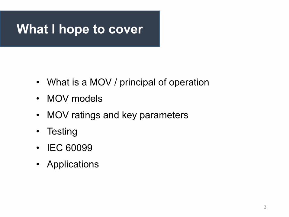
The gapless MOV
Source: Hubbel Power Systems, http://www.hubbellpowersystems.com/literature/arresters/dist/EU1377-H.pdf
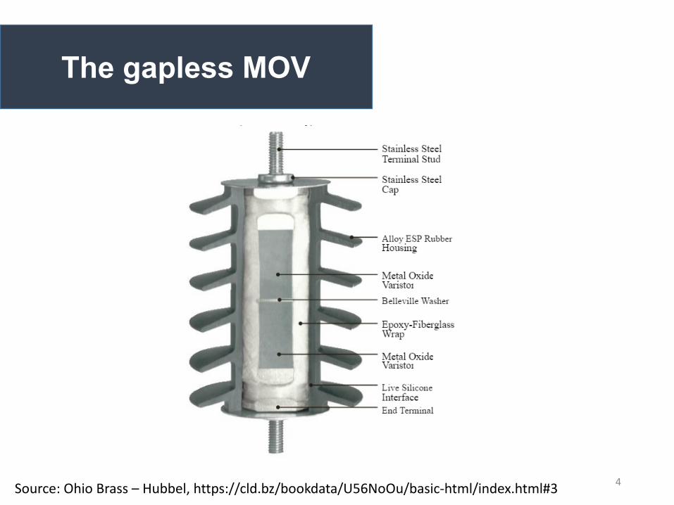
• The MOV is a pressed block of electrical grade metal oxide (ZnO, BiO) in a polymer cylinder surrounded by an insulating housing
• MOVs are used to attenuate lightning and switching surges• The characteristic shown shows equivalent resistance versus |V|• Used in distribution through transmission applications
4
The gapless MOV
Source: Ohio Brass – Hubbel, https://cld.bz/bookdata/U56NoOu/basic-html/index.html#3
5
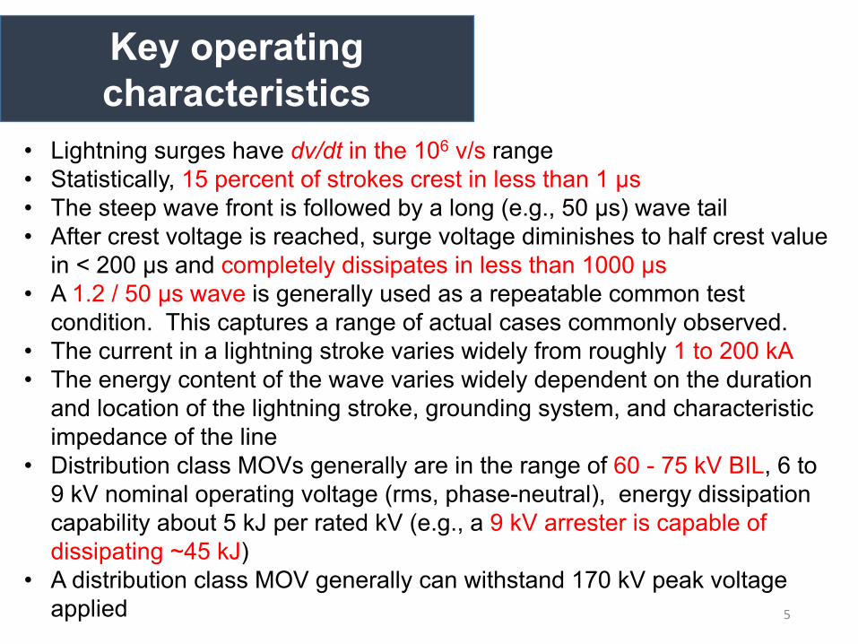
Key operating characteristics
• Lightning surges have dv/dt in the 106 v/s range• Statistically, 15 percent of strokes crest in less than 1 μs • The steep wave front is followed by a long (e.g., 50 μs) wave tail• After crest voltage is reached, surge voltage diminishes to half crest value
in < 200 μs and completely dissipates in less than 1000 μs • A 1.2 / 50 μs wave is generally used as a repeatable common test
condition. This captures a range of actual cases commonly observed.• The current in a lightning stroke varies widely from roughly 1 to 200 kA • The energy content of the wave varies widely dependent on the duration
and location of the lightning stroke, grounding system, and characteristic impedance of the line
• Distribution class MOVs generally are in the range of 60 - 75 kV BIL, 6 to 9 kV nominal operating voltage (rms, phase-neutral), energy dissipation capability about 5 kJ per rated kV (e.g., a 9 kV arrester is capable of dissipating ~45 kJ)
• A distribution class MOV generally can withstand 170 kV peak voltage applied
6
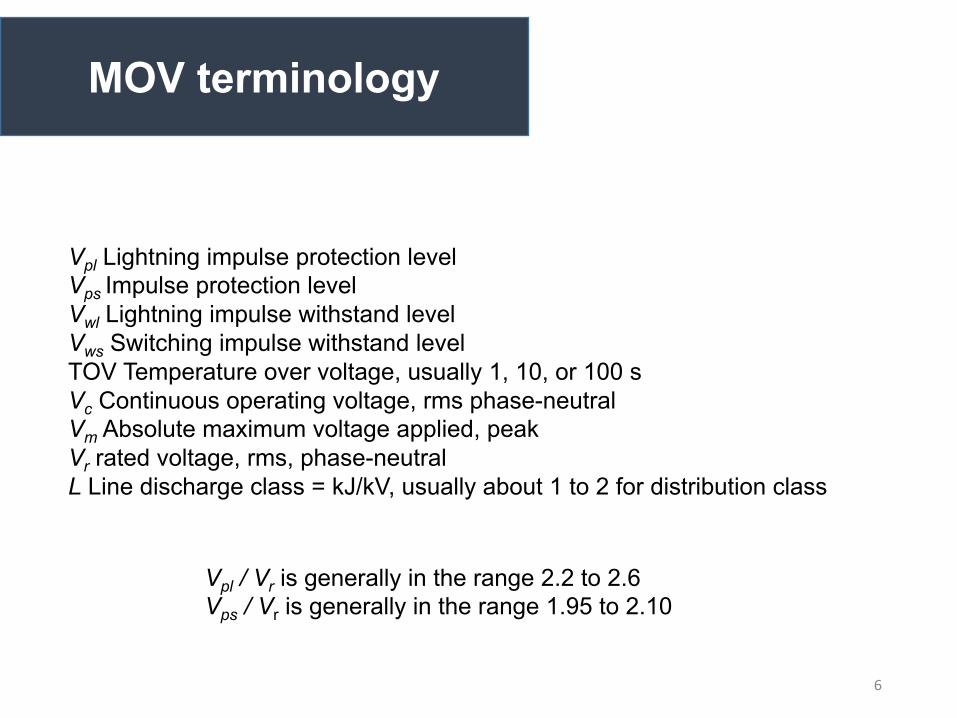
MOV terminology
Vpl Lightning impulse protection levelVps Impulse protection levelVwl Lightning impulse withstand levelVws Switching impulse withstand levelTOV Temperature over voltage, usually 1, 10, or 100 sVc Continuous operating voltage, rms phase-neutralVm Absolute maximum voltage applied, peakVr rated voltage, rms, phase-neutralL Line discharge class = kJ/kV, usually about 1 to 2 for distribution class
Vpl / Vr is generally in the range 2.2 to 2.6Vps / Vr is generally in the range 1.95 to 2.10

7
ANSI/IEEE Standard C62.11-1987 Describes Relevant Laboratory Tests For Distribution Class Surge Arresters:
1. Square Wave Energy - A sample of varistors are tested using a switching surge type waves of successively higher current.
2. High Current Test - This testing verifies the high current strength of the varistors.
3. AC Test —The active power loss and capacitive currents of a sample are measured.
4. Accelerated Aging Test
The MOV tests and standards
8
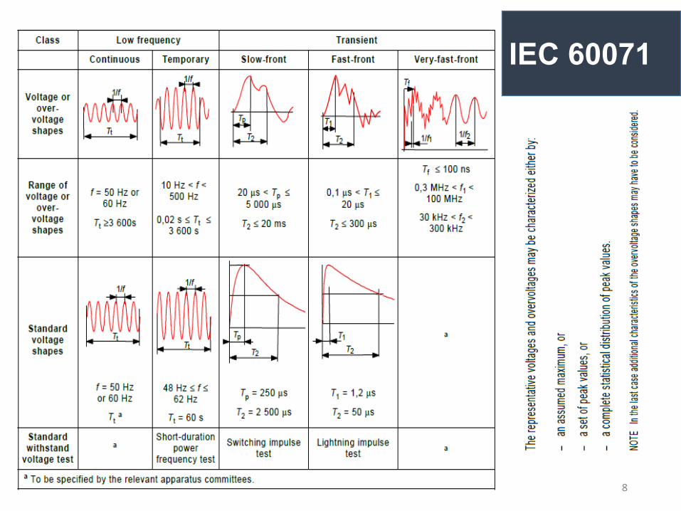
IEC 60071
9
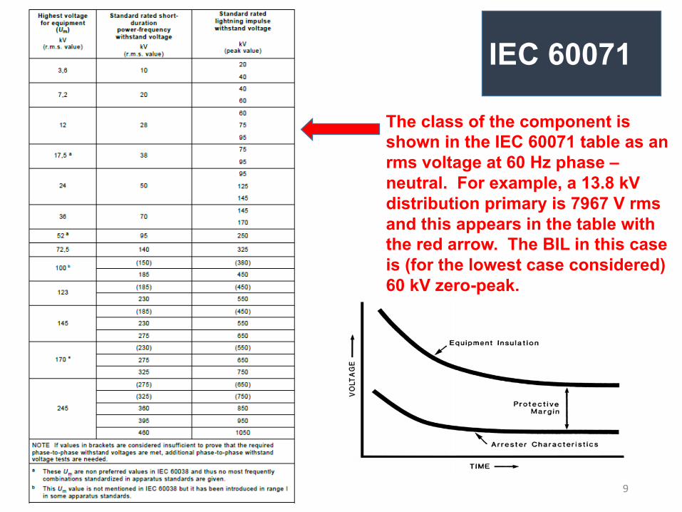
IEC 60071
The class of the component is
shown in the IEC 60071 table as an
rms voltage at 60 Hz phase –
neutral. For example, a 13.8 kV
distribution primary is 7967 V rms
and this appears in the table with
the red arrow. The BIL in this case
is (for the lowest case considered)
60 kV zero-peak.
10
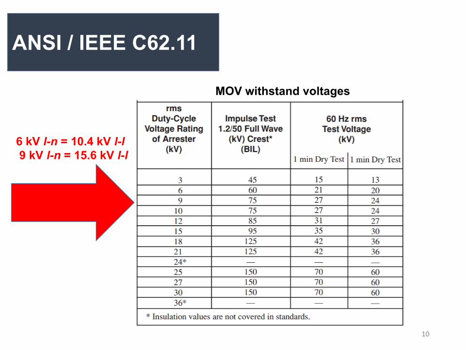
MOV withstand voltages
ANSI / IEEE C62.11
6 kV l-n = 10.4 kV l-l9 kV l-n = 15.6 kV l-l
11
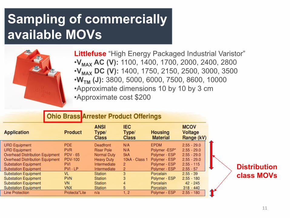
Sampling of commercially available MOVs
Littlefuse “High Energy Packaged Industrial Varistor”•VMAX AC (V): 1100, 1400, 1700, 2000, 2400, 2800•VMAX DC (V): 1400, 1750, 2150, 2500, 3000, 3500•WTM (J): 3800, 5000, 6000, 7500, 8600, 10000•Approximate dimensions 10 by 10 by 3 cm•Approximate cost $200
Distribution class MOVs
12
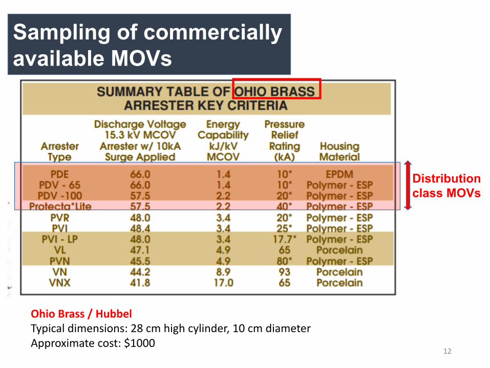
Sampling of commercially available MOVs
Distribution class MOVs
Ohio Brass / HubbelTypical dimensions: 28 cm high cylinder, 10 cm diameterApproximate cost: $1000
13
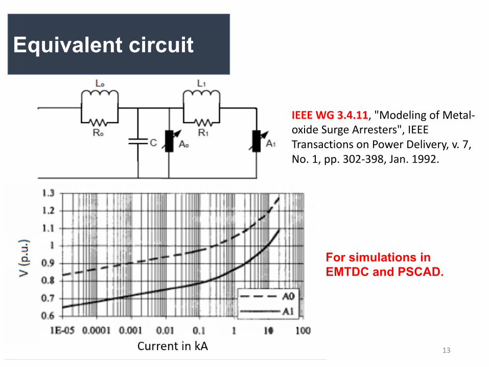
IEEE WG 3.4.11, "Modeling of Metal-oxide Surge Arresters", IEEE Transactions on Power Delivery, v. 7, No. 1, pp. 302-398, Jan. 1992.
Equivalent circuit
For simulations in EMTDC and PSCAD.
14
Speed of operation
According to [*], for miniature MOVs (BiO, ZnO) tests have been performed with current pulses of “0.5 ns rise time, 2 to 250 ns pulse widths up to 65 amp on devices with 1.4 cm diameter. There does not appear to be a "switching time" nor a dv/dt effect involved.”
“When a fast front voltage surge is applied to the device, its capacitance will immediately make it appear as low impedance and, when the capacitance is fully charged, the device will merely operate at the point corresponding to its V-I characteristic.”
For larger MOVs, rise times in the 0.5 μs range have been reported
NO RELIABLE DATA FOR MOV SWITCHING TIMES SEEM TO BE AVAILABLE FOR LINE DISCHARGE CLASS 1 OR 2 MOVs.
*J. D. Harnden, Jr., F. D. Martzloff, W. G. Morris, F. B. Golden, “GE – MOV VARISTOR --The Super Alpha Varistor,” General Electric Co., December 1972
15
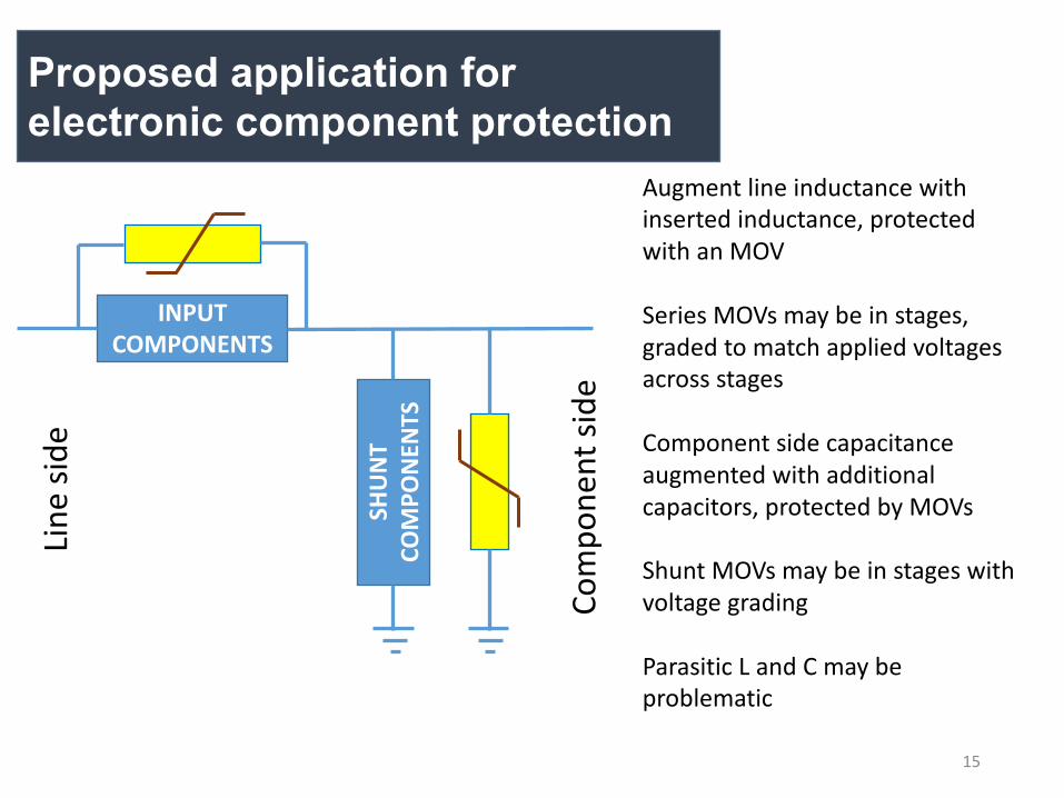
Proposed application for electronic component protection
INPUT COMPONENTS
SHUN
T CO
MPO
NENT
S
Line
side
Com
pone
nt si
de
Augment line inductance with inserted inductance, protected with an MOV
Series MOVs may be in stages, graded to match applied voltages across stages
Component side capacitance augmented with additional capacitors, protected by MOVs
Shunt MOVs may be in stages with voltage grading
Parasitic L and C may be problematic
16
Steady state losses
Gapless surge arresters typically dissipate 50 mWper kV [*] rated voltage so a 24 kV rated arrester dissipates 1.2 W continuously.
[*] Cooper Power Systems publication B235- 08033: “Taking Protection to the Extremes: UltraSIL Polymer-Housed Distribution-Class Surge Arrester”.
17
Conclusions
MOVs appear to be the best available protection in distribution applications
They should be used with components that are compliant with the BIL requirements at the input side
Ohmic (galvanic) isolation is not assured
Steady state losses in MOVs are not a problem
Impulse testing is required
Parasitics may be a problem

18
![PSERC Webinar - September 27, 2011 · Results PSERC Webinar –September 27, 2011 10 . PSERC Webinar – September 27, 2011 11 Vehicle class c B c [kWh] Max Min 1 12 8 2 14 10 3 21](https://img.pdfslide.us/doc/110x75/5f55e17bc0a96a097e326b5e/pserc-webinar-september-27-2011-results-pserc-webinar-aseptember-27-2011-10.jpg)