Embed Size (px)
Citation preview

PSEN op4F/H-A series
Operating Manual-1003067-EN-04
Safety light curtain

Preface
This document is a translation of the original document.
All rights to this documentation are reserved by Pilz GmbH & Co. KG. Copies may be made
for internal purposes. Suggestions and comments for improving this documentation will be
gratefully received.
Pilz®, PIT®, PMI®, PNOZ®, Primo®, PSEN®, PSS®, PVIS®, SafetyBUS p®, SafetyEYE®,
SafetyNET p®, the spirit of safety® are registered and protected trademarks of Pilz GmbH
& Co. KG in some countries.
SD means Secure Digital
1 GENERAL INFORMATION ......................................................... 51.1 General description ................................................................................................. 5
1.1.1 General description of the safety light curtain.......................................................... 5
1.1.2 Package content ..................................................................................................... 6
1.2 Guidelines for selecting the protective device ......................................................... 7
1.2.1 Resolution ............................................................................................................... 7
1.2.2 Height of protected field .......................................................................................... 8
1.2.3 Minimum safety distance ........................................................................................ 9
1.3 Typical application areas .......................................................................................12
1.4 Safety information ..................................................................................................13
2 INSTALLATION ........................................................................ 142.1 Precautions to be taken during selection and installation of a light curtain .............14
2.2 General information on positioning the device........................................................15
2.2.1 Minimum distance from reflective surfaces ............................................................16
2.2.2 Distances between identical light curtains ..............................................................17
2.2.3 Aligning transmitter and receiver ............................................................................20
2.2.4 Using deviating mirrors ..........................................................................................20
2.2.5 Inspections following a first-time installation ...........................................................21
3 MECHANICAL ASSEMBLY ...................................................... 23
4 ELECTRICAL CONNECTIONS ................................................. 254.1 Connection guidelines ............................................................................................28
5 ALIGNMENT ............................................................................. 31
6 SETTING THE FUNCTIONS ..................................................... 336.1 Reset to factory configuration ................................................................................35
6.2 Function list ...........................................................................................................36
7 FUNCTIONS .............................................................................. 387.1 Restart function ......................................................................................................38
7.2 Test .......................................................................................................................40
7.3 Reset .....................................................................................................................41
7.4 EDM ......................................................................................................................41
7.5 EDM selection ........................................................................................................43
7.6 Reduced range ......................................................................................................43
7.7 Muting ....................................................................................................................44
7.7.1 Disabling the muting function .................................................................................45
7.7.2 Muting display devices ...........................................................................................45
7.7.3 Typical muting application and sensor connection .................................................46
7.7.4 Muting direction .....................................................................................................46
7.7.5 Muting timeout .......................................................................................................50
7.7.6 Muting filter ............................................................................................................51
7.7.7 Partial muting .........................................................................................................52
7.8 Override .................................................................................................................53
7.8.1 Override mode .......................................................................................................54
7.8.2 Override timeout ....................................................................................................55
7.8.3 Override restart ......................................................................................................56
7.9 Blanking .................................................................................................................59
7.9.1 Fixed blanking ........................................................................................................60
7.9.2 Fixed blanking with increased tolerance .................................................................61
7.9.3 Floating blanking with total surveillance .................................................................61
7.9.4 Floating blanking with partial surveillance ..............................................................61
7.9.5 Reduced resolution ................................................................................................62
7.9.6 Tolerance ...............................................................................................................62
7.9.7 Blanking mode in the basic configuration ...............................................................64
7.9.8 Blanking mode in advanced configuration ..............................................................65
7.10 Cascading ..............................................................................................................68
7.11 PNP/NPN ...............................................................................................................68
7.12 Coding ...................................................................................................................70
8 DIAGNOSTICS .......................................................................... 738.1 Status of LEDs .......................................................................................................73
9 REGULAR CHECKS AND MAINTENANCE ............................. 769.1 Regular checks ......................................................................................................76
9.2 Maintenance ..........................................................................................................76
10 TECHNICAL DETAILS .............................................................. 77
11 LIST OF AVAILABLE MODELS ............................................... 78
12 DIMENSIONS ............................................................................ 80
13 FITTINGS .................................................................................. 81
14 ACCESSORIES ........................................................................ 8314.1 Rotating mounting bracket .....................................................................................83
14.2 Cascading cable ....................................................................................................84
14.3 Connection cable ...................................................................................................85
14.4 PSEN op Advanced Programming Adapter ............................................................86
14.5 Axial connection cable, unshielded ........................................................................88
14.6 Ethernet cable for PSEN op Advanced Programming Adapter ...............................88

OPERATING MANUAL PSEN op4F/H-A series
1 GENERAL INFORMATION
1.1 General description
1.1.1 General description of the safety light curtain
The safety light curtains in the PSEN op4F/H-A series are multibeam active optoelectronic protective devices for work areas in which machines, robots and automated plants in general could endanger the physical integrity of operators who could come into contact with moving parts, even if only by chance. Light curtains in the PSEN op4F/H-A series are designed as inherently safe Type 4 systems for accident prevention in accordance with applicable international safety standards, in particular the following:
IEC 61496-1: 2004 Safety of machinery: Electrosensitive protective equipment. Part 1: General requirements and tests.
IEC 61496-2: 2006 Safety of machinery: Electrosensitive protective equipment – Particular requirements for equipment using active optoelectronic protective devices. A light curtain pair consists of a transmitter and a receiver. They produce an infrared protected field, which is able to detect an opaque object within the specific resolution. Both the transmitter and the receiver have control and monitoring functions. The connections are made via an M12 connector, which is located in the lower profile area. The transmitter and receiver are synchronised optically, so the two units do not have to be connected directly to each other. The infrared beams that are transmitted and received are controlled and monitored via a microprocessor, which provides the user with information about the operating state of the light curtain via LED indicators (see Chapter 8). A light curtain pair consists of 2 units, which may comprise one or more transmitter and receiver modules, depending on the respective model. The receiver is the main control unit for all functions. If an error occurs, it checks all the safety actions and decides on the measures that are to be implemented in terms of safety, as well as performing other general functions.
During the installation phase the user interface makes it easier to align the two units (see Chapter 5). As soon as the beams emitted from the transmitter are interrupted by an object, a limb or the body of an operator, both output signal switching devices (OSSD) are opened immediately. This controls the stopping of the corresponding machine, which is connected to the OSSD.
Some parts or paragraphs of this manual, which are of particular importance to the user or installation engineer, are highlighted as follows:
The information contained in paragraphs marked by this symbol is particularly relevant to safety and is important for accident prevention. This information must be read with particular attention and must be strictly observed.
1003067-EN-04 5

OPERATING MANUAL PSEN op4F/H-A series
This manual contains all the information you need to select and operate the protective devices. Specialised knowledge of safety issues is required to integrate a safety light curtain correctly in a plant. PILZ’s technical customer service team is available to provide any information you need regarding the functionality of the PSEN op4F/H-A safety light curtains and the safety regulations concerning correct installation.
1.1.2 Package content The following components are included:
• Receiver (RX)
• Transmitter (TX)
• Shortform for installing the safety light curtains in the PSEN op4F/H-A series
• CD with operating manual and other documents
• 4 fastening brackets and corresponding mounting accessories
• 2 fastening brackets for models with a height between 1200 and 1800 mm
6 1003067-EN-04

OPERATING MANUAL PSEN op4F/H-A series
1.2 Guidelines for selecting the protective device Once the hazards have been assessed appropriately, there are at least three essential features to consider when selecting a safety light curtain:
1.2.1 Resolution The device’s resolution is understood to be the minimum size that an opaque object must be to safely interrupt at least one of the beams that form the area of the protected field. The resolution is closely linked to the part of the body that requires protection.
R = 14 mm Finger protection
Type 4
R = 30 mm Hand protection
Type 4
As shown in Fig. 1, the resolution depends solely on the geometric properties of the lenses, the diameter and the distance and so is unaffected by the light curtain’s ambient and operating conditions.
Fig. 1– Resolution
1 = Opaque object 2 = Height of protected
field 3 = Operating range
The resolution value can be calculated using the following formula:
R = I + d where: I = Distance between two adjacent lenses d = Lens diameter
1003067-EN-04 7

OPERATING MANUAL PSEN op4F/H-A series
1.2.2 Height of protected field
The height of the protected field is understood to be the height protected by the safety light curtain.
Fig. 2 – Height of protected field
1 = Protected field 2 = Height of protected
field 3 = Operating range
The height monitored by the PSEN op4F/H-A corresponds to the overall height of the light curtain. With reference to the previous diagram, the height of the protected field can be taken from the table below.
Model Height of protected field
(mm)
PSEN op4F-A-14-030/1
PSEN op4H-A-30-030/1 300
PSEN op4F-A-14-045/1
PSEN op4H-A-30-045/1 450
PSEN op4F-A-14-060/1
PSEN op4H-A-30-060/1 600
PSEN op4F-A-14-075/1
PSEN op4H-A-30-075/1 750
PSEN op4F-A-14-090/1
PSEN op4H-A-30-090/1 900
8 1003067-EN-04

OPERATING MANUAL PSEN op4F/H-A series
PSEN op4F-A-14-105/1
PSEN op4H-A-30-105/1 1050
PSEN op4F-A-14-120/1
PSEN op4H-A-30-120/1 1200
PSEN op4F-A-14-135/1
PSEN op4H-A-30-135/1 1350
PSEN op4F-A-14-150/1
PSEN op4H-A-30-150/1 1500
PSEN op4F-A-14-165/1
PSEN op4H-A-30-165/1 1650
PSEN op4F-A-14-180/1
PSEN op4H-A-30-180/1 1800
1.2.3 Minimum safety distance The protective device must be positioned at a specific safety distance (Fig. 3), which guarantees that the operator cannot reach the danger zone until the hazardous machine movement has come to a standstill by triggering the light curtain. In accordance with the standard ISO 13855, this distance depends on 4 factors:
• Response time of the light curtain (the time that elapses between the beams beingeffectively interrupted and the OSSD contacts opening).
• Machine’s stopping performance (time that elapses between the light curtain contactsopening and the hazardous machine movement effectively stopping).
• Light curtain’s resolution
• Approach speed of the object to be detected.
Fig. 3 – Safety distance (vertical)
H1 = ≥ 900 mm at a resolution > 40 mm H2 = ≤ 300 mm at a resolution > 40 mm S = Minimum safety distance in mm
1003067-EN-04 9

OPERATING MANUAL PSEN op4F/H-A series
The safety distance is calculated using the following formula:
S = K (t1 + t2) + C Therefore: S Minimum safety distance in mm K Speed of the object (limb or body) approaching the danger zone in mm/s t1 Light curtain’s response time in seconds (see Chapter 11) t2 Machine’s stopping performance in seconds C Additional distance based on the possibility of placing the body or limb into the danger
zone before the protective device responds C 8 (d -14) for devices with a resolution ≤ 40 mm C 850 mm for devices with a resolution > 40 mm
d Device’s resolution
Note: The value K corresponds to:
• 2000 mm/s, if the calculated value S is ≤ 500 mm• 1600 mm/s, if the calculated value S is > 500 mm
When using light curtains with a resolution of > 40 mm, the upper beam must be positioned at a height of ≥ 900 mm (H2) from the supporting base, while the lower beam must be positioned at a height of ≤ 300 mm (H1). Where the light curtain must be installed horizontally (Fig. 4), the distance between the danger zone and the most distant optical beam must correspond to the value calculated using the following formula:
S = 1600 mm/s (t1 + t2) + 1200 – 0.4 H Therefore:
S Minimum safety distance in mm t1 Light curtain’s response time in seconds (see Chapter 11) t2 Machine’s stopping performance in seconds H Height of the beams above the floor. This height must always be less than 1000 mm.
Fig. 4 – Safety distance (horizontal)
10 1003067-EN-04

OPERATING MANUAL PSEN op4F/H-A series
Application examples This example is based on a light curtain with a height = 600 mm. To calculate the distance of the device from the light curtain in a vertical position, the following formula is applied:
S = K*T + C Therefore: T = t1 + t2 t1 = Response time of light curtain + release time of relay (specific time of PNOZ S3: 20ms) With a reaction time of the light curtain of 15 ms the result is a max. of 35 ms for t1
t2 = Machine’s overall stopping performance in seconds C = 8 * (d – 14) for devices with resolution <= 40 mm D = Resolution
In each case, if K = 2000 mm/sec, then S > 500 mm. The safety distance will then need to be recalculated, based on K = 1600 mm/sec.
WARNING: In this case the reference standard is EN ISO 13855 “Safety of machinery – Positioning of protective equipment in respect of approach speeds of parts of the human body”. The information provided here should be regarded as a summary and is non-binding. Please refer to the complete standard ISO 13855 for details of how to calculate safety distances correctly.
1003067-EN-04 11

OPERATING MANUAL PSEN op4F/H-A series
1.3 Typical application areas
Example 1: Protecting the operating area on drilling machines The operator inserts the workpiece and removes it after machining. The operator must be protected from injury during the machining process. Solution: The safety light curtain PSEN op4F/H-A is particularly suitable for this application, as the device needs to be installed directly on the machine. Benefits: The small dimensions of the light curtain guarantee maximum flexibility during installation, as it can be adapted to the machine dimensions. Rotatable mounting brackets are included, guaranteeing fast, simple attachment.
Example 2: Bending presses The safety device must protect the bending process operator from the crushing hazard that exists between the upper and lower tool or from the workpiece that is being machined, if this approaches at high speed.
Solution: Even if just one light axis on the safety light curtain PSEN op4F/H-A is interrupted during the downward phase, the movable workpiece carrier is stopped immediately.
Benefits: The simple installation options and the small dimensions of the safety light curtain mean it can be used in most bending operations. PSEN op4F/H-A not only guarantees a high level of reliability but also increases production on the plant, as the standstill times needed for access, settings and machine maintenance can be reduced.
Example 3: Paper cutting machine A typical application for these protective devices is on paper cutting machinery for magazines
and special formats. The purpose of the light curtain is to protect the operator from cuts or abrasions from the cutting machine.
Solution: The safety light curtain PSEN op4F/H-A is particularly suitable for this application, as the device needs to be installed directly on the machine. Benefits: The small dimensions of the light curtain and the guide rails at either end guarantee maximum flexibility, as they can be adapted to the machine’s mechanical
dimensions.
12 1003067-EN-04

OPERATING MANUAL PSEN op4F/H-A series
Example 4: Moulding machine The moulding machine is used to create complex shapes from metallic parts or parts made from other materials. In this case it is necessary to prevent the operator’s hands or other limbs being dragged, entangled or cut by the tool itself or being injured by the spindle.
Solution: The safety light curtain from the PSEN op4F/H-A series is the best solution for protecting the operator in terms of the required safety level and the application type. As soon as even a single beam on the light curtain is interrupted, the machine is stopped immediately.
Benefits: The small dimensions of the light curtain with no dead zones guarantees maximum flexibility during installation, as it can be adapted to the machine dimensions.
1.4 Safety information
To use the safety light curtains in the PSEN op4F/H-A series safely and correctly, the following information must be considered:
• The system intended to stop the machine must be electrically controllable.
• This control system must be able to stop hazardous machine movements- inside the overall stopping performance of the machine T,- in accordance with the details in Chapter 1.2.3 of the operating manual (see CD provided)- and in each phase of the processing cycle.
• The protective device must be positioned at a distance that exceeds the minimum safetydistance S or that corresponds to it, so that the operator cannot reach the danger zone until themovement of the hazardous object has come to a standstill by triggering the light curtain.
• The safety light curtains may only be installed and connected by qualified personnel. It isessential to follow the instructions provided in the relevant sections of the manuals provided(see Chapters 2, 3, 4 and 5) and to comply with the applicable directives.
• Ensure that the correct operation of the light curtain is not disturbed by strong electromagneticinterference.
• Ensure that the light curtain, particularly the receiver, is not installed close to particularlyintense and/or flashing light sources.
• The safety light curtain must be positioned so that it safely prevents access to the danger zonewithout interrupting the beams (see Chapters 2, 3).
• Only qualified personnel with appropriate knowledge of all the operating procedures of thesafety light curtain should be permitted to work within the danger zone.
• The RESET button must be positioned outside the area of the protected field and in such away that the operator can see into the danger zone when carrying out a reset and testprocedure.
• Reflective surfaces close to the beams emitted from the protective device (whether fromabove, below or from the side) can cause passive reflections that adversely affect the correctoperation of the light curtain.
The instructions provided for correct operation must be strictly followed before switching on the light curtain.
1003067-EN-04 13

OPERATING MANUAL PSEN op4F/H-A series
2 INSTALLATION
2.1 Precautions to be taken during selection and installation of a light curtain
Ensure that the safety level guaranteed by the PSEN op4F/H-A (Type 4) complies with the actual risk assessment of the machine to be monitored, as well as the level defined by the standard EN ISO 13849.
Ensure that the light curtain’s outputs (OSSD) are used as machine stopping devices and not as control devices. The machine must have a separate START control.
Ensure that the correct operation of the light curtain is not disturbed by strong electromagnetic interference.
Ensure that the light curtain, particularly the receiver, is not installed close to particularly intense and/or flashing light sources.
• The size of the smallest object to be detected must be greater than the device’s resolution.
• The light curtain must be installed in an environment that complies with the technical propertiesstated in Chapter 11.
• Smoke, mist or dust in the working environment can reduce the operating range of theprotective device.
• Sudden, large-scale temperature variations, particularly with low temperatures can generate aslight layer of condensation on the device’s lens, adversely affecting its function.
• Reflective surfaces close to the beams emitted from the protective device (whether from above,below or from the side) can cause passive reflections that adversely affect the correct operationof the light curtain.
• The protective device must be positioned at a distance that exceeds the minimum safetydistance S or that corresponds to it, so that the operator cannot reach the danger zone until themovement of the hazardous object has come to a standstill by triggering the light curtain.
14 1003067-EN-04

OPERATING MANUAL PSEN op4F/H-A series
2.2 General information on positioning the device Special care should be taken when positioning the safety light curtain to ensure it provides efficient protection. The device must be installed so that the danger zone cannot be accessed without interrupting the protected field.
Fig. 5 shows some possibilities for accessing the machine from above and below. Situations like this could turn out to be extremely dangerous. For this reason, the safety light curtain must be installed at a height from which access to the danger zone can be covered in full (Fig. 6).
Fig. 5 – Device positioned incorrectly
Fig. 6 – Device positioned correctly
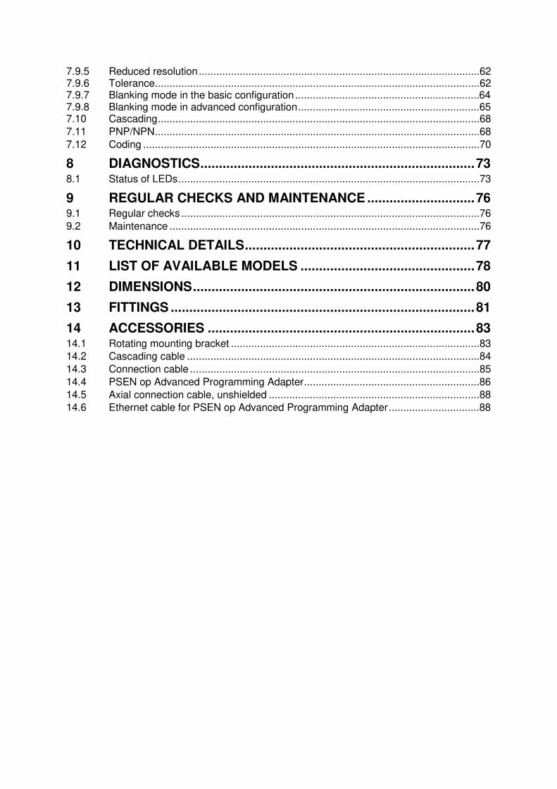
Under normal operating conditions, the machine may only be started if the operator is outside the danger zone. If it is impossible to install the light curtain in the immediate vicinity of the danger zone, the possibility of access from the side must be excluded, for example, by installing a second horizontal light curtain. See Fig. 8.
If the operator is able to enter the danger zone, additional mechanical protection must be installed to exclude access.
NO
YES
1003067-EN-04 15
OPERATING MANUAL PSEN op4F/H-A series
Fig. 7 Fig. 8
2.2.1 Minimum distance from reflective surfaces Reflective surfaces close to the beams emitted from the protective device (whether from above, below or from the side) can cause passive reflections. These passive reflections can adversely affect how the object is detected within the protected area. If the receiver RX detects a secondary beam (reflected by the side-reflecting surface), the object may not be detected even if it interrupts the main beam.
DANGER ZONE
Reflective surface
Reflective surface
Fig. 9 Minimum distance from reflective surfaces
When installing the safety light curtain it is important to maintain a minimum distance from reflective surfaces.
NO YES
16 1003067-EN-04

OPERATING MANUAL PSEN op4F/H-A series
This minimum distance depends on the following factors: • The distance between the transmitter (TX) and receiver (RX)
• The actual opening angle of the light curtain; in particular:
when Type 4 light curtain = 5° (α = ± 2.5°)
The illustration in Fig. 10 shows the minimum distance from the reflective surface (Dsr) based on the operating range:
Fig. 10
Formula for calculating Dsr: Dsr (m) = 0.15 With operating ranges < than 3 m Dsr (m) = 0.5 x operating range (m) x
tg 2α With operating ranges ≥ than 3 m
2.2.2 Distances between identical light curtains Should it be necessary to install several protective devices in adjacent areas, care must be taken to ensure that the transmitter on one of the pairs does not dangerously interfere with the receiver on another pair. The interfering transmitter, TX B, must be installed outside the minimum distance Ddo from the TX A - RX A axis of the transmitter/receiver pair.
Fig. 11 – Distance between devices of the same type
This minimum distance Ddo depends on the following factors: • The distance between the transmitter (TX A) and receiver (RX A);
• The actual opening angle of the light curtain.
Light curtain Type 4
Operating range
Dis
tance f
rom
re
flective
surf
ace
1003067-EN-04 17

OPERATING MANUAL PSEN op4F/H-A series
The following graphic shows the distance from the interfering devices (Ddo), based on the operating range (Dop) of the pair (TX A – RX A).
Fig. 12
For the purpose of simplification, the table below states the values of the minimum safety distances required for installation, with reference to some operating ranges.
Operating range (m)
Minimum safety distance (m)
3 0.3 6 0.4
10 0.5 19 0.6
WARNING: The interfering transmitter (TX B) must be positioned at the same distance Ddo, as calculated above, even if the distance from the other transmitter TX A is shorter than from the receiver RX A.
Reichweite Operating range
Dis
tance
be
twe
en
tw
o
de
vic
es o
f th
e s
am
e typ
e
18 1003067-EN-04

OPERATING MANUAL PSEN op4F/H-A series
Fig. 13 shows an example of an installation in which interference may occur, along with two potential remedies.
Opaque partition
Fig. 13 – Interference between adjacent light curtains
Should it be necessary to install two light curtains adjacently, as shown in the example in Fig. 13, the coding function is available as a possible solution (see section 7.12).
NO
YES
YES
1003067-EN-04 19

OPERATING MANUAL PSEN op4F/H-A series
2.2.3 Aligning transmitter and receiver The light curtain pair must be arranged in parallel to each other. Transmitter and receiver have connections underneath. Both units must be installed at the same time. Make sure that the light curtains are not configured as shown in Fig. 14.
Fig. 14 – Light curtain alignment
2.2.4 Using deviating mirrors If a single safety device is used, danger zones with different but adjacent access sides can be monitored using well-positioned deviating mirrors. Fig. 15 shows a possible solution, which can be used to protect three access sides using two mirrors. The deviating mirrors should be positioned at a 45° angle to the light axes.
Fig. 15- Using deviating mirrors
When deviating mirrors are used, the following precautions must be taken and conditions considered:
• When deviating mirrors are used, the alignment of the transmitters and receivers requireshigher precision. Perfect alignment can be lost even with only a minor angular displacement ofthe mirror. In this case we recommend you use the laser pointer, which is available as anaccessory.
• The minimum safety distance (S) must be maintained for all sections of the beam.
• Use of a single deviating mirror reduces the effective operating range by about 15%. Thispercentage increases when two or more deviating mirrors are used (more detailed informationis provided in the technical specifications for the relevant mirror).
NO NO
Mirror Mirror
DANGER ZONE
20 1003067-EN-04

OPERATING MANUAL PSEN op4F/H-A series
The table below states the operating ranges based on the number of mirrors used.
Number of mirrors
Operating range (14 mm)
Operating range (30 mm)
1 5.1 m 16.5 m 2 4.3 m 13.7 m 3 3.7 m 11.6 m
• Never use more than three mirrors per device.
• Any dust or dirt on the mirror’s reflective surface will drastically reduce the operating range.
2.2.5 Inspections following a first-time installation Listed below are the control measures that must be taken following a first-time installation, prior to starting the machine. Tests must be carried out by qualified personnel or directly by the person in charge of machinery safety / under his or her supervision.
Fig. 16 – Path of test object
1003067-EN-04 21

OPERATING MANUAL PSEN op4F/H-A series
Perform the following checks:
• The light curtain is in a safe state (OSSDs off)- The beams are interrupted across the whole area of the protected field using a test
object (test rod) (TP-14 or TP-30) with an appropriate resolution, in accordance withthe diagram in Fig. 16.
• Is the light curtain aligned correctly?- Press gently on the side of the product in both directions. The red LED must not light
during this process
•Activate the TEST function on the TX side.- The OSSD outputs are opened (red LED, OSSD on the RX side, ON and stop of the
controlled machine).
• The response time to the status of the machine STOP, including the response time ofthe light curtain and machine, is within the limit values defined for calculating the safetydistance (see Chapter 2.2).
• The safety distance between the danger zones and the light curtain complies with thedetails specified in Chapter 2.2.
•Access and exposure of persons between the light curtain and hazardous machinecomponents is prevented.
• It is impossible to access the machine’s danger zones from an unprotected side.
• In order to guarantee that the light curtain remains in NORMAL FUNCTION MODE for atleast 10-15 minutes and, after positioning the specific test object in the protected field,stays in a SAFE STATE for the same time span, there must be no interference fromexternal light sources.
• Check that all additional functions comply by activating them several times underdifferent operating conditions.
22 1003067-EN-04

OPERATING MANUAL PSEN op4F/H-A series
3 MECHANICAL ASSEMBLY
The transmitter (TX) and receiver (RX) must be assembled with their sensing surfaces facing each other. The connectors must be positioned on the same side and the distance must be within the operating limits of the relevant model (see Chapter 11).
The pair of light curtains must be aligned to the best possible extent and must be as parallel as possible. The devices will be precision aligned in accordance with the description in Chapter 5. When positioning the pair of light curtains, please note that the length of the receiver is increased by 56.9 mm if the PSEN op Advanced Programming Adapter is used and is built into the light curtain.
The fastening kit supplied can be used as follows (Fig. 17).
To assemble the kit with the mounting brackets, place the bolts into the dedicated side guide rail. Slide the insert along the groove of the metal profile. Attach the bracket by tightening the M5 hexagonal nuts on the profile. It is possible to slide the bracket unit along the dedicated rail and then reposition it by tightening the above-mentioned nuts.
Fig. 17 – Procedure with fixed mounting brackets
On applications where there is particularly heavy vibration, we recommend that you use anti-vibration rubbers with the mounting brackets to alleviate the effects of the vibration.
Fig. 18 - Anti-vibration rubbers
1003067-EN-04 23

OPERATING MANUAL PSEN op4F/H-A series
The mounting positions recommended based on the length of the light curtain are stated in Fig. 19 and in the following table.
Fig. 19 – Light curtain dimensions
MODEL L (mm) L (mm) incl. PSEN op
advanced programming
adapter
A (mm) B (mm) C (mm)
PSEN op4F-A-14-030/1 PSEN op4H-A-30-030/1
306.3 363.2 86.3 110 -
PSEN op4F-A-14-045/1 PSEN op4H-A-30-045/1
456.3 513.2 236.3 110 -
PSEN op4F-A-14-060/1 PSEN op4H-A-30-060/1
606.2 663.1 306.2 150 -
PSEN op4F-A-14-075/1 PSEN op4H-A-30-075/1
756.2 813.1 406.2 175 -
PSEN op4F-A-14-090/1 PSEN op4H-A-30-090/1
906.1 963.0 506.1 200 -
PSEN op4F-A-14-105/1 PSEN op4H-A-30-105/1
1056.1 1113.0 606.1 225 -
PSEN op4F-A-14-120/1 PSEN op4H-A-30-120/1
1206 1262.9 966 150 453
PSEN op4F-A-14-135/1 PSEN op4H-A-30-135/1
1356 1412.9 1066 175 503
PSEN op4F-A-14-150/1 PSEN op4H-A-30-150/1
1505.9 1562.8 1166 200 553
PSEN op4F-A-14-165/1 PSEN op4H-A-30-165/1
1655.9 1712.8 1266 225 603
PSEN op4F-A-14-180/1 PSEN op4H-A-30-180/1
1805.8 1862.7 1366 250 652.9
24 1003067-EN-04

OPERATING MANUAL PSEN op4F/H-A series
4 ELECTRICAL CONNECTIONS 18-pin rectangular pigtail cables are used at the light curtain for electrical connections. Thepigtail cable has M12 connectors with a different number of pins on the opposite side.On muting models, the receiver is equipped with one 12-pin M12 connector and one 5-pinM12 connector.On blanking models, the receiver is equipped with one 12-pin M12 connector.The transmitter has one 5-pin M12 connector (on both muting and blanking models).After removing the cap shown in grey (see Fig.) the cables must be connected at the bottomof the light curtain (the end with LEDs and buttons).
Make sure that the terminator cap (see Chapter 13) is connected on the top of the light curtain. If this connection is missing, the Master and Slave units will switch to a critical communication state.
NOTE: The RX connections on the 12-pin M12 cable for the muting model and the 12-pin M12 cable for the blanking model are different, so it is important to use the right cable for each configuration (connector with two M12s for the muting configuration and one M12 for the blanking configuration).
PSENopt Advanced RX Muting
18
pin
M12 12 pin
M12 5 pin
M12 12-Pin: 1. 24 V (brown)2. 0 V (blue)3. RESET/RESTART/ALIGN (white)4. OVERRIDE1 (green)5. OSSD2 (pink)6. EDM (yellow)7. MUTING DEACTIVATION (black)8. OSSD1 (grey)9. OVERRIDE2 (red)10. MUTING LAMP (purple)11. OVERRIDE STATUS (grey-pink)
12. EARTHING (red-blue)
M12 5-Pin:
1. 24 V (brown)
2. MUTING2 (white)
3. 0 V (blue)
4. MUTING1 (black)
5. NC (grey)
1003067-EN-04 25

OPERATING MANUAL PSEN op4F/H-A series
PSENopt Advanced RX Blanking 1
8 p
in
M12 12 pin
M12 12-Pin:
1. 24 V (brown)
2. 0 V (blue)
3. RESET/RESTART/ALIGN (white)
4. TEACH IN (green)
5. OSSD2 (pink)
6. EDM (yellow)
7. NC (black)
8. OSSD1 (grey)
9. TOLERANCE (red)
10. LAMP (purple)
11. NC (grey-pink)
12. EARTHING (red-blue)
PSENopt Advanced TX
18
pin
M12 5 pin
M12 5-Pin:
1. 24 V (brown)
2. TEST (white)
3. 0 V (blue)
4. EARTH (black)
5. REDUCED RANGE (grey)
Assignment of M12 connector
12-pin 5-pin
PSENopt Advanced RX MutingCONNECTION LINE BEHAVIOUR
RESET 24Vdc
IN line N.O.Is connected – when in disabled state the RESET/RESTART/ALIGN button is operated
RESTART 24Vdc
IN line N.O.Is connected – when during operation the RESET/RESTART/ALIGN button is operated
ALIGNMENT 24Vdc
IN line N.O. Has to be set to 24 V DC at startup
OVERRIDE 1 24Vdc
IN line N.O.Is connected – when Override is active during operation
OVERRIDE 2 IN line N.O. No voltage – during operation
EDM See section 7.4 for connections
Must be non-equivalent to OSSD during operation with EDM enabled
MUTING DEACTIVATION
24Vdc
IN line N.O. Muting is disabled when connecting
26 1003067-EN-04

OPERATING MANUAL PSEN op4F/H-A series
PSENopt Advanced RX MutingCONNECTION LINE BEHAVIOUR
OSSD1 / OSSD 2
0V
OSSDs
Protected field clear No voltage = Protected field not clear
OVERRIDE STATUS
0V
OSSDs
High level = Override function active Low level = Override function inactive
NOTE: This line signals the state of the override signal inputs
MUTING LAMP
24Vdc
LAMP
The open collector connection is activated when muting is activated.
MUTING1/MUTING2 24Vdc
IN line N.O.Is connected – when muting is active during operation
FUNCTION EARTH Connect to earth
PSENopt Advanced RX Blanking CONNECTION LINE BEHAVIOUR
RESET 24Vdc
IN line N.O.Is connected – when in disabled state the RESET/RESTART/ALIGN button is operated
RESTART 24Vdc
IN line N.O.Is connected – when during operation the RESET/RESTART/ALIGN button is operated
ALIGNMENT 24Vdc
IN line N.O. Has to be set to 24 V DC at startup
TEACH-IN 24Vdc
IN line N.O.Is connected – when TEACH-IN button is operated during operation
TOLERANCE 24Vdc
IN line N.O. Has to be set to 24 V DC at startup
EDM See Chapter 7.4 for connections
Must be non-equivalent to OSSD during operation with EDM enabled
OSSD1 / OSSD 2
0V
OSSDs
Protected field clear No voltage = Protected field not clear
BLANKING LAMP
24Vdc
LAMP
The open collector connection is switched when blanking is activated.
FUNCTION EARTH
Connect to earth
PSENopt Advanced TX CONNECTION LINE BEHAVIOUR
TEST 24Vdc
IN line N.O.is connected, when the RESET button is operated during operation
REDUCED RANGE 24Vdc
IN line N.O.Has to be set to 24 V DC at startup
FUNCTION EARTH Connect to earth
1003067-EN-04 27

OPERATING MANUAL PSEN op4F/H-A series
4.1 Connection guidelines The following section contains some guidelines regarding the connections, which should be followed to ensure the correct operation of the safety light curtain from the PSEN op4F/H-A series.
• Never place connection cable close to or in contact with cables featuring high voltageratings and/or current fluctuations (e.g.: motor supply, inverters etc.).
• Never combine the OSSD wires from several safety light curtains into one multi-polecable.
• The TEST wire must be connected to the light curtain’s operating voltage via apushbutton with N/O contact.
• Use the light curtain with protection class III and SEL/PELV power supplies for thevoltage.
The RESET button must be positioned so that the user can check the protected field during each test.
The RESET/RESTART/ALIGN button must be positioned so that the user can check the protected field during all reset operations.
• Use the light curtain with protection class III and SELV/PELV power supplies for thevoltage supply.
Example: Connection to the safety relay
Automatic start
Fig. 20 – Connection to safety relay – automatic start
28 1003067-EN-04

OPERATING MANUAL PSEN op4F/H-A series
Manual start
Fig. 21 – Connection to safety relay – manual start
The diagrams show the connection between the safety light curtains and the safety relay PNOZ s3 in automatic start mode (Fig. 20) and monitored manual start mode (Fig 21).
• Avoid using varistors, RC circuits or LEDs in parallel to the relay inputs or in seriesconnection to the OSSD outputs.
• The safety contacts of OSSD1 and OSSD2 may not be connected in series or inparallel, but must be used separately (Fig. 22).
• Should one of these configurations be used by mistake, the device switches to anoutput error condition (see Chapter 8.).
• Connect both OSSDs outputs individually to the safety relay. Other configurations havea negative effect on the safety of the system and are not permitted.
Fig. 22 – Correct OSSD signal load connection Fig. 23 – Incorrect OSSD signal load connection (I)
Fig. 24 – Incorrect OSSD signal load connection (II)
Fig. 25 – Incorrect OSSD signal load connection (III)
NO NO
YES NO
1003067-EN-04 29

OPERATING MANUAL PSEN op4F/H-A series
NOTE: The OSSDs are pulsed. The following diagram shows the time characteristic of the OSSDs.
115 µs
500 ms
1000 ms
OSSD in safe state
OSSD2
OSSD1
24 V DC
GND24 V DC
GND
Fig. 26 – Time characteristic of the OSSDs
30 1003067-EN-04

OPERATING MANUAL PSEN op4F/H-A series
5 ALIGNMENT The transmitter and receiver must be aligned to ensure the device operates correctly. Good alignment prevents the light curtain switching incorrectly due to dust or vibration. The optimum alignment is achieved when the optical axes of the first and last beam from the transmitter coincide with the optical axes of the corresponding elements on the receiver. The light curtain has two synchronisation beams. The lower synchronisation beam, the first beam in the protected field, is called SYNC1 and the synchronisation beam on the opposite side of the light curtain, the last beam in the protected field, is called SYNC2. The illustration shows that the first beam is on the lower edge of the light curtain, next to the LED display. The last beam is on the opposite side, next to the terminator cap.
Fig. 27 – Beam description
1 = First beam SYNC1 2 = Beam of protected field 3 = Last beam SYNC2
The alignment function can be activated by simultaneously switching 24 V at the input RESET/RESTART/ALIGN (Pin 3/ 12-pin connector) during startup. The activated alignment mode is shown when the second LED starts flashing (red) (see Fig. 28). Then the RESET/RESTART/ALIGN input can be switched without voltage again. When successful alignment has been reached, the light curtain is returned to normal operating mode by switching off and then on again.
OFF
ON
RESET/RESTART/ALIGN
STATE OF LIGHT CURTAIN (POWER ON)
0 V DC
24 V DC
ON
OFF
RED LED FLASHES
ON
OFF
STATE OF LIGHT CURTAIN (ALIGN)
Fig. 28 – Alignment timings
1003067-EN-04 31

OPERATING MANUAL PSEN op4F/H-A series
In alignment mode, the light curtain is always in a safe state and the OSSD outputs are OFF. The quality and level of the alignment is determined via the signal strength of each individual beam in alignment mode. The two synchronization beams have a higher value level. The user can see the alignment quality from the LED state at the lower end of the receiver.
A. Hold the receiver in a stable position and align the transmitter until the yellow SYNC1LED goes out. This state confirms that the first synchronisation beam has beenaligned.
B. Rotate the transmitter around the axis of the lower lens until the yellow SYNC2 LEDgoes out.
C. For precision adjustment, make minor movements of the transmitter and receiver toachieve the optimum quality
D. Attach both units firmly using the mounting brackets. Check that the LEVEL of thereceiver does not decrease in quality and that the light axes are not interrupted. Thencheck that all LEDs on the LEVEL display go out, even if only one beam isinterrupted. This test is conducted using a test object TP-14 or TP-30 correspondingto the resolution (see Chapter 2.2.5).
E. Switch off the light curtain pair and then switch it back on in normal operating mode.The alignment level is also monitored by the display during normal operation (seeChapter 8.1). Once the light curtain has been aligned and fastened appropriately, theLED display proves perfect for checking the alignment and displaying any change inthe ambient conditions (e.g. dust).
Display Configuration LED RX Alignment
status Alignment
Status of OSSD in normal
operating mode
No sync, check SYNC1
NONE OFF
SYNC1 aligned NONE OFF
SYNC2 aligned NONE OFF
One or more intermediate beams not aligned
NONE OFF
All light axes are aligned
POOR ON
All light axes are aligned
ON
All light axes are aligned
ON
All light axes are aligned
EXCELLENT ON
Fig. 29 –Status of the LED displays in alignment mode
32 1003067-EN-04

OPERATING MANUAL PSEN op4F/H-A series
6 SETTING THE FUNCTIONS There are two options for configuring the light curtain’s functions and operating configurations: - Basis configuration mode (BCM):In basic configuration mode you have the option to use the buttons and the LED interface(transmitter/receiver) to select basic functions/parameters.
- Advanced configuration mode (ACM):In advanced configuration mode you have the option to use the PC softwarePSENopt Configurator (only for the receiver) to select advanced functions/parameters. Forconfiguration via software the PSEN op Advanced Programming Adapter is required.
CAUTION: Configuration via ACM will overwrite a configuration created via BCM! A new BCM configuration can only be created when the ACM configuration is deleted. This protects the light curtain from accidental changes.
Basic configuration mode The user interface consists of 8 LEDs and 3 protected pushbuttons and enables the user to perform the basic configuration. The LEDs are the same LEDs used to display status in normal operating mode. A plastic pen is provided (see Chapter 13), which the user must use to activate the pushbuttons, thus preventing unwanted access to the safety configuration.
Basic configuration steps On the right-hand side of the operator panel at transmitter and receiver there is a settings interface, consisting of three pushbuttons. The interfaces give users the option to set the light curtain locally, without using the PSENopt Configurator.
• CONFIRM button activates the BCM configuration mode
• SELECT button: The different functions are run through.
• ENABLE button: Activates and deactivates the currently selected function.
The individual steps are described below:
1. Press the CONFIRM button and keep it held down to switch to basic configurationmode.
2. The light curtain runs through a test cycle. With the transmitter the LEDs 2 and 3 lightup one after the other, with the receiver the LEDs 2 to 8. The Power LED 1 isconstantly lit.After the test cycle is completed, the current configuration is displayed
3. Use the SELECT function to choose the function that is to be set. The LED for theselected function will flash.
4. Now configure the selected function by pressing the ENABLE button (LED lights/goesout).
5. Repeat steps 3 and 4 until the required configuration is displayed.6. Press the CONFIRM button and keep it held down to save the new configuration.
If an advanced configuration has already been set on the light curtain (via the PSENopt Configurator on the PC), pressing the button just once during step 2 will generate a
1003067-EN-04 33
OPERATING MANUAL PSEN op4F/H-A series
light curtain configuration error, which prevents non-authorised changes to the advanced configuration.
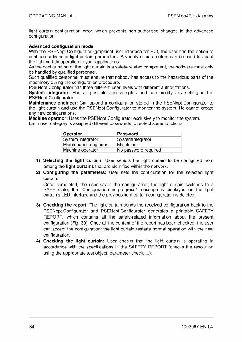
Advanced configuration mode With the PSENopt Configurator (graphical user interface for PC), the user has the option to configure advanced light curtain parameters. A variety of parameters can be used to adapt the light curtain operation to your applications. As the configuration of the light curtain is a safety-related component, the software must only be handled by qualified personnel. Such qualified personnel must ensure that nobody has access to the hazardous parts of the machinery during the configuration procedure. PSENopt Configurator has three different user levels with different authorizations. System integrator: Has all possible access rights and can modify any setting in the PSENopt Configurator. Maintenance engineer: Can upload a configuration stored in the PSENopt Configurator to the light curtain and use the PSENopt Configurator to monitor the system. He cannot create any new configurations. Machine operator: Uses the PSENopt Configurator exclusively to monitor the system. Each user category is assigned different passwords to protect some functions.
Operator Password
System integrator SystemIntegrator Maintenance engineer Maintainer Machine operator No password required
1) Selecting the light curtain: User selects the light curtain to be configured from
among the light curtains that are identified within the network.
2) Configuring the parameters: User sets the configuration for the selected light
curtain.
Once completed, the user saves the configuration; the light curtain switches to aSAFE state; the “Configuration in progress” message is displayed on the lightcurtain’s LED interface and the previous light curtain configuration is deleted.
3) Checking the report: The light curtain sends the received configuration back to the
PSENopt Configurator and PSENopt Configurator generates a printable SAFETY
REPORT, which contains all the safety-related information about the present
configuration (Fig. 30). Once all the content of the report has been checked, the user
can accept the configuration: the light curtain restarts normal operation with the new
configuration.
4) Checking the light curtain: User checks that the light curtain is operating in
accordance with the specifications in the SAFETY REPORT (checks the resolution
using the appropriate test object, parameter check, ...).
34 1003067-EN-04

OPERATING MANUAL PSEN op4F/H-A series
Fig. 30 – Safety report
Identification of light curtain
• Serial no.
• Firmware version
• Configuration ID (check sum of configuration parameters)Position of light curtain in a cascading Model name and characteristic data of the light curtain (resolution) Current protected field configuration (muting or blanking) Configuration parameters for blanking/muting
6.1 Reset to factory configuration The user has the option to re-establish the light curtain’s factory configuration by operating the pushbuttons as described below:
1. Press the CONFIRM button and keep it held down for at least 9 s (but not more than30 s, so that the light curtain is not blocked)
2. The LEDs flash briefly, indicating that the light curtain has been reset to the factoryconfiguration
3. After the reset has occurred, the light curtain resumes its normal operation with thefactory configuration.
NOTE: Restoring the factory settings will delete the BCM and the ACM configuration.
1003067-EN-04 35

OPERATING MANUAL PSEN op4F/H-A series
6.2 Function list PSEN op4F/H-A has two main operating modes: blanking and muting. The settings of the functions at the receiver associated with LEDs 5 to 8 will change, depending on whether blanking or muting is selected.
NOTE: The table highlights the default configuration in bold.
Legend for LED display in RX/TX function list
LED off, LED is not relevant for the information in the “Function” column LED off, LED is relevant for the information in the “Function” column LED yellow, value in the “Setting” column is valid for the information in the “Function” column LED red, value in the “Setting” column is valid for the information in the “Function” column LED green, value in the “Setting” column is valid for the information in the “Function” column
List of RX functions in muting mode (LED 3 lights up yellow)
Function LED No.
Setting LED status
PW
R
OS
SD
ED
M
AC
M LEVEL
Coding 2 Code 1
Code 2
No code
Selection of muting/blanking
3 Muting
Blanking
EDM 4 Activated
Deactivated
Restart mode 5 Auto
Manual
Muting direction 6 T (bidirectional)
L (one-directional)
Muting timeout 7 10 min
Infinite
Activation of override
8 Level
Edge
36 1003067-EN-04

OPERATING MANUAL PSEN op4F/H-A series
List of RX functions in blanking mode (LED 3 OFF)
Function LED No.
Setting LED status
PW
R
OS
SD
ED
M
AC
M LEVEL
Coding 2 Code 1
Code 2
No code
Selection of muting/blanking
3 Muting
Blanking
EDM 4 Activated
Deactivated
Restart mode 5 Auto
Manual
Selection of floating blanking
6-7 Floating blanking deactivated
Floating blanking 1 beam
Floating blanking 2 beams
Reduced resolution 4 beams
Selection of fixed blanking
8 1 fixed blanking zone
2 fixed blanking zones
List of TX functions
Function LED No.
Setting LED status
PW
R
TS
T
SR
LR
CODE
Coding 2 Code 1
Code 2
No code
Selection of operating range
3 Normal
Reduced
1003067-EN-04 37

OPERATING MANUAL PSEN op4F/H-A series
7 FUNCTIONS
7.1 Restart function If the beams detect an opaque object, the OSSD output switching elements will switch (i.e. the safety contacts will open, SAFETY conditions). The restart function enables the user to define how the light curtain returns from the safe state to normal operation. There are two ways to restart the light curtain (i.e. close the OSSD safety contacts – SAFETY condition): automatic or manual restart.
Automatic restart: If an opaque object is detected, the light curtain switches to a SAFE CONDITION. If the object is then removed from the protected field, the light curtain will resume its normal operation. The response time is the time that elapses between the object being introduced to the protected field and the OSSD achieving the OFF state (SAFETY); the reset time is the time it takes for the OSSD to switch to the ON state (SAFETY) after all the objects have been removed. All these times are functions that are dependent on length, as illustrated below.
Fig. 31 – Restart timings (auto)
In automatic restart mode, the RESET/RESTART/ALIGN input (Pin 3 of the 12-pin M12 connector – RX-side) must not be activated.
Fig. 32 – Restart connection (auto)
38 1003067-EN-04

OPERATING MANUAL PSEN op4F/H-A series
Manual restart: When the light curtain has detected an opaque object in the protected field, the light curtain does not resume its normal operation until the object has been removed from the protected field and the reset button has been operated. The OSSD output switching elements switch back to normal operation when the RESTART signal voltage is removed again, and not after 500 ms. If the RESTART signal is present for longer than 5 s an error is generated, which blocks the light curtain.
Fig. 33 – Restart timings (manual)
In manual restart mode, the RESET/RESTART/ALIGN input (Pin 3 of the 12-pin M12 connector – RX-side) must be connected to a 24 VDC N/O contact.
Fig. 34 – Restart connection (manual)
WARNING: Hazardous conditions and the reset mode should be assessed carefully. When access to danger zones is protected, automatic reset mode is potentially unsafe if it enables the operator to pass through the zone before the sensing area is active. In this case it will be necessary to use a manual restart or, for example, the manual restart on the relay PNOZ s3 (see Chapter 4.).
1003067-EN-04 39

OPERATING MANUAL PSEN op4F/H-A series
The section below describes how the restart mode can be selected via the pushbutton as well as via the user interface.
BCM configuration: Restart mode
PW
R
OS
SD
ED
M
AC
M
LEVEL
Auto LED 5 red (ON)
Manual LED 5 OFF
ACM configuration: Restart mode
7.2 Test The TEST function can be activated by operating the 24 VDC N/O pushbutton connected to the TEST input on the TX device (Pin 2 of the 5-pin M12 connector) for at least 0.5 seconds. The TEST disables the transmission level, so the RX-side sees the beams as interrupted and the OSSD go low within the response time. As shown on the timing diagram below, the OSSDs switch to the OFF state (INTERRUPTION STATE) after 500 ms (plus one cycle time) and after the light curtain's response time.
Fig. 35 – Test timings
40 1003067-EN-04
OPERATING MANUAL PSEN op4F/H-A series
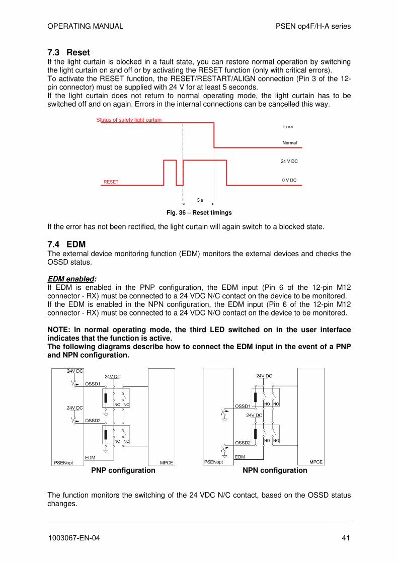
7.3 Reset If the light curtain is blocked in a fault state, you can restore normal operation by switching the light curtain on and off or by activating the RESET function (only with critical errors). To activate the RESET function, the RESET/RESTART/ALIGN connection (Pin 3 of the 12-pin connector) must be supplied with 24 V for at least 5 seconds. If the light curtain does not return to normal operating mode, the light curtain has to be switched off and on again. Errors in the internal connections can be cancelled this way.
Fig. 36 – Reset timings
If the error has not been rectified, the light curtain will again switch to a blocked state.
7.4 EDM The external device monitoring function (EDM) monitors the external devices and checks the OSSD status.
EDM enabled: If EDM is enabled in the PNP configuration, the EDM input (Pin 6 of the 12-pin M12 connector - RX) must be connected to a 24 VDC N/C contact on the device to be monitored. If the EDM is enabled in the NPN configuration, the EDM input (Pin 6 of the 12-pin M12 connector - RX) must be connected to a 24 VDC N/O contact on the device to be monitored.
NOTE: In normal operating mode, the third LED switched on in the user interface indicates that the function is active. The following diagrams describe how to connect the EDM input in the event of a PNP and NPN configuration.
PNP configuration NPN configuration
The function monitors the switching of the 24 VDC N/C contact, based on the OSSD status changes.
1003067-EN-04 41

OPERATING MANUAL PSEN op4F/H-A series
PNP configuration NPN configuration
Fig. 37 – EDM timings
The EDM status is not equivalent to that of the OSSD: the timing diagram illustrates the relationship between cause (OSSD) and effect (EDM), with the maximum permitted delay.
Tc ≥ 350 ms (time between the OSSD transition from OFF-ON and the EDM test)
To ≥ 100 ms (time between the OSSD transition from OFF-ON and the EDM test)
(two different times for the mechanical, positive-guided contact)
EDM disabled: If EDM is disabled, the EDM input may not be connected.
PNP configuration NPN configuration
Fig. 38 – EDM connections
42 1003067-EN-04

OPERATING MANUAL PSEN op4F/H-A series
7.5 EDM selection This function enables users to select or exclude monitoring of the external switching devices.
BCM configuration: EDM selection
PW
R
OS
SD
ED
M
AC
M
LEVEL
Activated LED 4 ON yellow
Deactivated LED 4 OFF
ACM configuration: EDM selection
To increase the safety level when EDM is OFF when the light curtain is commissioned, ensure that the EDM input is not connected.
7.6 Reduced range This function enables you to select the maximum operating range for the light curtain’s assembly. The table below summarises the different operating ranges for both resolutions, if the reduced operating range is changed.
Resolution 30 mm RX long range RX short range TX long range 20 m 6 m TX short range 12 m 4 m
Resolution 14 mm RX long range RX short range TX long range 7 m 2 m TX short range 4 m 1 m
You can select this function via ACM for the receiver and via BCM for the transmitter.
Fig. 39 – Reduced range
1003067-EN-04 43

OPERATING MANUAL PSEN op4F/H-A series
BCM configuration (TX-side): Reduced range
PW
R
OS
SD
ED
M
AC
M
LEVEL
Long LED 3 ON yellow
Reduced LED 3 OFF
ACM configuration (RX-side): Reduced range
If long range is selected, the TX and RX can be installed at the maximum permitted operating range. A reduced operating range is recommended for cases in which several pairs of light curtains need to be assembled side by side and the coding function cannot be used.
7.7 Muting The muting function guarantees that the safety function is automatically disabled over all or part of the height of the detection zone, to enable specific, cyclical work operations to be carried out without having to stop the machine operation. In accordance with safety requirements, the light curtain is equipped with two inputs for activating the muting function, MUTING1 and MUTING2. The muting sensors must be able to detect the conveyed material (pallets, vehicles,…) based on their length and speed. Where there are variable conveyor speeds within the muting area, you must consider the effect this will have on the overall duration of the muting process.
• The muting function excludes the light curtain during operation and maintains theOSSD output switching elements in an activated state, based on the specific operatingrequirements (Fig. 40).
L-Version with integratedmuting sensors for muting inone direction
T-Version with integrated mutingsensors for muting in twodirections
Linear version with external muting sensors
Fig. 40 – Application examples for the muting function
• In accordance with the applicable standards, the safety light curtain has two inputs(MUTING1 and MUTING2) to activate this function.
• This function is particularly suitable for cases in which an object, but not a person,needs to pass through the danger zone under certain conditions.
44 1003067-EN-04

OPERATING MANUAL PSEN op4F/H-A series
• It is important to note that the muting function represents a hazardous situation of thedevice. So it must be applied only in keeping with the necessary preventive measures.
• The muting sensors must be correctly positioned to avoid unintended muting becomingpotentially dangerous for the operator.
• MUTING1 and MUTING2 cannot be activated simultaneously.
• The muting status is displayed via an external muting lamp (which can be connected tothe light curtain via Pin 10 of the 12-pin M12 connector) and via various LEDs on theuser interface. If the muting function is ON, the LAMP and LEDs start to flash.
• During installation, ensure that the lamp is positioned so that it is as visible as possible.
• If the external lamp is broken and/or not connected, a muting call will result in aSAFETY BLOCKING CONDITION and the relevant error message will be displayed.
Particular attention should be paid to the choice of configuration, as an incorrect configuration can cause the muting function to operate incorrectly and reduce the safety level.
The muting sensors must be arranged in such a way that the muting function cannot be activated by an operator who happens to pass through.
7.7.1 Disabling the muting function The muting function can be enabled and disabled dynamically during operation of the PSEN op4F/H-A. When disabled, no muting call is accepted at the inputs MUTING X and the safety function is constantly active. Users can deactivate the muting function during operation by applying 24 V at the DISABLE signal (Pin 7 of the 12-pin connector).
7.7.2 Muting display devices The corresponding display device (lamp) must be connected in order to use the muting function. If this device is not present, the light curtain will switch to a blocked state due to a defect. Both incandescent lamps and LED lamps are permitted. If you are using an LED lamp, make sure that the connection has the right polarity. When the lamp is switched on, a lamp TEST is carried out as part of each cycle, to ensure that any functional failure is detected. If the lamp is found to be broken, the light curtain will switch to a safe state and a corresponding message is shown on the display (see Chapter 10 for further information on the lamp).
1003067-EN-04 45

OPERATING MANUAL PSEN op4F/H-A series
7.7.3 Typical muting application and sensor connection
Fig. 41 – Typical muting application
The diagram above shows a typical muting application: the protection device installed on the conveyor must allow the package to pass through but not the operator. The light curtain temporarily suspends its safety function when the sensors A11, A21, A12, A22 are activated in the correct sequence. These may be optical or mechanical sensors that switch 24 V when the object is detected.
7.7.4 Muting direction The light curtain can be used for bidirectional muting (T-type, four sensors) as well as one-directional muting (L-type, two sensors).
• T-muting is used when objects can move through the light curtain in both directions.
• L-muting is used when objects move only in one direction.
In BCM mode the maximum activation delay between MUTING1 and MUTING2 (T12max) is 4 seconds T-MutingWith T-type operation, the device switches to the muting function if the signal from theMUTING2 input switches within a fixed T12max, after the MUTING1 signal has switched (orvice versa). The muting function ends as soon as the signal at MUTING1 or MUTING2 goeslow. Users can set the maximum activation delay between MUTING1 and MUTING2 (or viceversa) from a minimum of 1 second to a maximum of 16 seconds (T12max). Once this timehas elapsed, if users wish to switch to muting status they will need to deactivate the mutinginput and start the sequence again.
A11
A12A21
A22
Safety sensor
46 1003067-EN-04

OPERATING MANUAL PSEN op4F/H-A series
Fig. 42 – T muting timings
The sensors labelled A1/A2 are connected to the muting input (MUTING1) and the sensors labelled B1/B2 are connected to the MUTING2 input. Sensors ending in “1” are on the same side of the light curtain and therefore on the opposite side to the sensors ending in “2”.
“D” stands for the distance at which the sensors A1/A2 or B1/B2 must be installed and depends on the package length (L):
D < L
“d1” stands for the maximum distance required between the muting sensors and depends on the package speed (V):
d1max [cm] = V [m/s] * T12 [s] * 100,
“d2” stands for the maximum distance required to accept a muting request and depends on the package speed (V):
d2max [cm] = V [m/s] * T12 [s] * 100,
“T12” stands for the activation delay between MUTING1 and MUTING2, which the operator can select via ACM.
Fig. 43 – T-Muting connection
1003067-EN-04 47

OPERATING MANUAL PSEN op4F/H-A series
L-MutingWith L-muting, the light curtain is muted if the input signals switch to 24 VDC in accordancewith a certain sequence: MUTING1 must be activated first; only then can MUTING2 beactivated.If MUTING2 should activate before MUTING1, the device will not switch to muting mode;“T12” represents the activation delay between MUTING1 and MUTING2, which users canselect via ACM.The muting function ends once the time has elapsed, which corresponds to a multiple of theactivation delay between the two sensors (this time corresponds to m * T12). The value “m”(multiplier T12) must be selected by the user. With BCM, 2 is the default value.In the ACM configuration, users can set the maximum activation delay between MUTING1and MUTING2 (or vice versa) from a minimum of 1 second to a maximum of 16 seconds(T12max). Once this time has elapsed, if users wish to switch to muting status they will needto deactivate the muting input and start the sequence again.
Fig. 44 – L-muting timings
The sensor labelled A is positioned furthest away from the light curtain, which is why its beam is recorded first. With reference to the diagram below and in consideration of the fact that the package only passes from right to left, sensor B cannot be recorded first. If this should happen, the light curtain is not muted. “V” indicates a constant velocity. As a result, “d1” can be calculated in accordance with the following formula:
d1 [cm] = V [m/s] * T12 [s] * 100
Fig. 45 – L-Muting connection
48 1003067-EN-04

OPERATING MANUAL PSEN op4F/H-A series
BCM configuration: Muting direction
PW
R
OS
SD
ED
M
AC
M
LEVEL
T (bidirectional) LED 6 ON green
L (one-directional) LED 6 OFF
ACM configuration: Muting direction
1003067-EN-04 49

OPERATING MANUAL PSEN op4F/H-A series
7.7.5 Muting timeout The muting timeout describes the time for the maximum duration of the muting function; once the timeout has elapsed, muting is ended. Users have the option to set this time in BCM as well as ACM mode. In BCM mode they can select the timeout to be 10 minutes long or infinite; “infinite” means that the muting timeout may potentially never end: as long as the muting conditions are present, the muting function will be maintained.
NOTE: This does not comply with the standard IEC 61496-1 and the user is informed of this fact via a message
Fig. 46 – Muting timeout
Users have the option in the ACM mode set the muting timeout in increments of 1 minute between 10 min und 1080 min. Alternatively, it can also be set to be infinite.
BCM configuration: Muting timeout
PW
R
OS
SD
ED
M
AC
M
LEVEL
10 min LED 7 ON green
Infinite LED 7 OFF
ACM configuration: Muting-Timeout
NOTE: The infinite timeout option does not comply with the standard IEC 61496-1 and the user is warned accordingly.
50 1003067-EN-04

OPERATING MANUAL PSEN op4F/H-A series
.
7.7.6 Muting filter This function prevents muting from being activated unintentionally. The muting filter is a filter arranged on the muting inputs: Transitions of the muting signal from high to low are only considered valid if they are maintained for a period (Tf) of over 100 ms. If this function is disabled, the logic level of the muting sensors will correspond to the signal level on the wire.
ACM configuration: Muting filter
Fig. 47 – Muting filter disabled Fig. 48 – Muting filter enabled
1003067-EN-04 51

OPERATING MANUAL PSEN op4F/H-A series
7.7.7 Partial muting
The muting type can be configured: total or partial muting. Partial muting can prove useful when the user wishes to limit the effects of the muting function exclusively to the selected zones. With ACM configuration, the user can select a maximum of 5 muting zones, each of which is defined in accordance with the following parameters: - Position: First beam of muting zone (starting from the user display cover).- Dimensions: Number of beams in muting zone
ACM configuration: Selection of partial muting
Select to enable the "partial muting" function.
• To add a new muting zone above the selected area:Click the "Add area" button and then select: "Add after selected beam"
• To add a new muting zone below the selected area:Click the "Add area" button and then select: "Add before selected beam"
• To remove an existing muting area:Click the "Remove selected area" button.
• Setting the muting zone:Enter the values for dimensions and position of an area in the software. The display of thesoftware is adapted accordingly. When performing step "2 Programming" and the report hasbeen accepted, these values are also set in the light curtain or in the PSEN op AdvancedProgramming Adapter.
52 1003067-EN-04

OPERATING MANUAL PSEN op4F/H-A series
7.8 Override The override function allows the user to disable the safety functions if the machine needs to be restarted, even though one or more of the light curtain beams have detected an object in the protected field. For example, a typical application would be to examine recurring blockages more precisely and to rectify the cause. These may be work materials between the light curtain’s transmitter and receiver, which trigger the light curtain.
The override’s redundant inputs must be connected to a 24 VDC N/O contact and an earthed N/O contact. In accordance with the guidelines, the light curtain is equipped with two override activation inputs: OVERRIDE1 and OVERRIDE2 (respectively, Pin 4 of the 12-pin M12 connector and Pin 9 of the 12-pin M12 connector – of the receiver).
Fig. 49 – Override connection
The condition for the override is that the light curtain must be in a SAFE STATE and at least one muting sensor must have been interrupted. If this condition is met, the user interface shows “override call status” and both the red LED on the OSSDs and the LEDs for the alignment function flash.
OVERRIDE CALL STATUS
As a result, the override request will only be accepted if the signals at the OVERRIDE X inputs comply with the timings shown below. The override function is ended automatically if any of the following conditions is present:
• All muting sensors are deactivated (with a T-muting configuration).
• All muting sensors are deactivated and no beams are interrupted (with an L-mutingconfiguration).
• The preset time limit has elapsed.
• The requirements for activation are no longer met (e.g. an override input is deactivated).
1003067-EN-04 53
OPERATING MANUAL PSEN op4F/H-A series
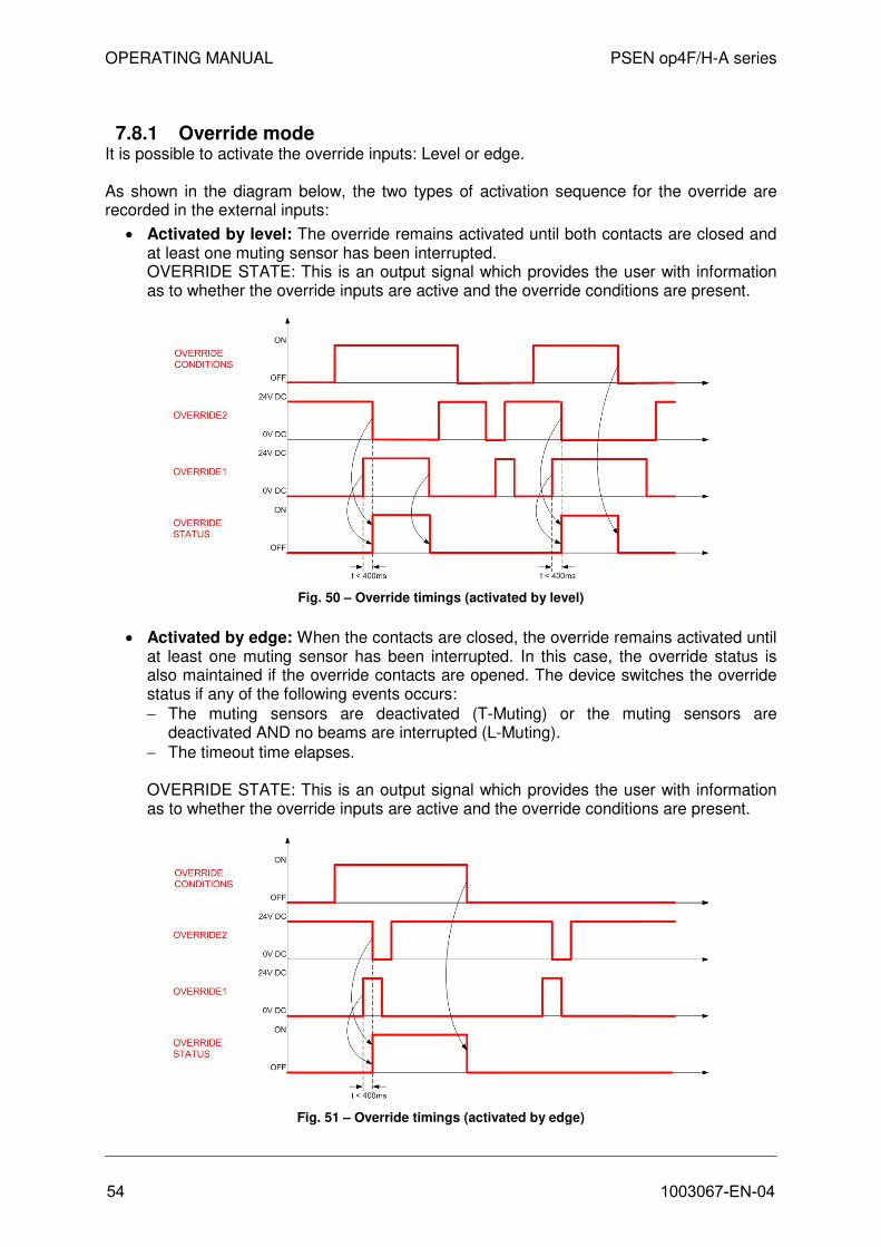
7.8.1 Override mode It is possible to activate the override inputs: Level or edge.
As shown in the diagram below, the two types of activation sequence for the override are recorded in the external inputs:
• Activated by level: The override remains activated until both contacts are closed andat least one muting sensor has been interrupted.OVERRIDE STATE: This is an output signal which provides the user with informationas to whether the override inputs are active and the override conditions are present.
Fig. 50 – Override timings (activated by level)
• Activated by edge: When the contacts are closed, the override remains activated untilat least one muting sensor has been interrupted. In this case, the override status isalso maintained if the override contacts are opened. The device switches the overridestatus if any of the following events occurs:
− The muting sensors are deactivated (T-Muting) or the muting sensors aredeactivated AND no beams are interrupted (L-Muting).
− The timeout time elapses.
OVERRIDE STATE: This is an output signal which provides the user with informationas to whether the override inputs are active and the override conditions are present.
Fig. 51 – Override timings (activated by edge)
54 1003067-EN-04
OPERATING MANUAL PSEN op4F/H-A series
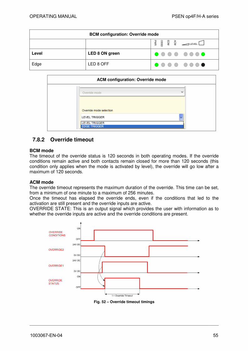
BCM configuration: Override mode
PW
R
OS
SD
ED
M
AC
M
LEVEL
Level LED 8 ON green
Edge LED 8 OFF
ACM configuration: Override mode
7.8.2 Override timeout
BCM mode The timeout of the override status is 120 seconds in both operating modes. If the override conditions remain active and both contacts remain closed for more than 120 seconds (this condition only applies when the mode is activated by level), the override will go low after a maximum of 120 seconds.
ACM mode The override timeout represents the maximum duration of the override. This time can be set, from a minimum of one minute to a maximum of 256 minutes. Once the timeout has elapsed the override ends, even if the conditions that led to the activation are still present and the override inputs are active. OVERRIDE STATE: This is an output signal which provides the user with information as to whether the override inputs are active and the override conditions are present.
Fig. 52 – Override timeout timings
1003067-EN-04 55

OPERATING MANUAL PSEN op4F/H-A series
ACM configuration: Override timeout
7.8.3 Override restart This can only be selected when the light curtain is in manual restart mode; users can select the type of override restart: normal or automatic. The RESET/RESTART/ALIGN input (Pin 3 of the 12-pin M12 connector – RX-side) must be connected to a 24 V DC N/O contact.
Fig. 53 – Override restart connection
56 1003067-EN-04

OPERATING MANUAL PSEN op4F/H-A series
Automatic override restart The OSSD output switching elements resume normal operation when the RESTART signal goes low and not after 500 ms. With a timeout of 5 s on RESTART with 24 V an error is generated, which blocks the light curtain. The output signals switch to 24 VDC after a time period that represents the maximum value between the reset time and the high restart time (greater than or equal to 500 ms). This time period may lie between 500 ms and 5 s. Once the override is ended, the OSSDs return to a normal operating state if the beams are not interrupted. OVERRIDE STATE: This is an output signal which provides the user with information as to whether the override inputs are active and the override conditions are present.
Fig. 54 – Override restart timings (auto)
ACM configuration: Selection of automatic override restart
NOTE: This selection does not comply with the standard IEC 61496-1 and the user will be informed of this fact via a message.
1003067-EN-04 57
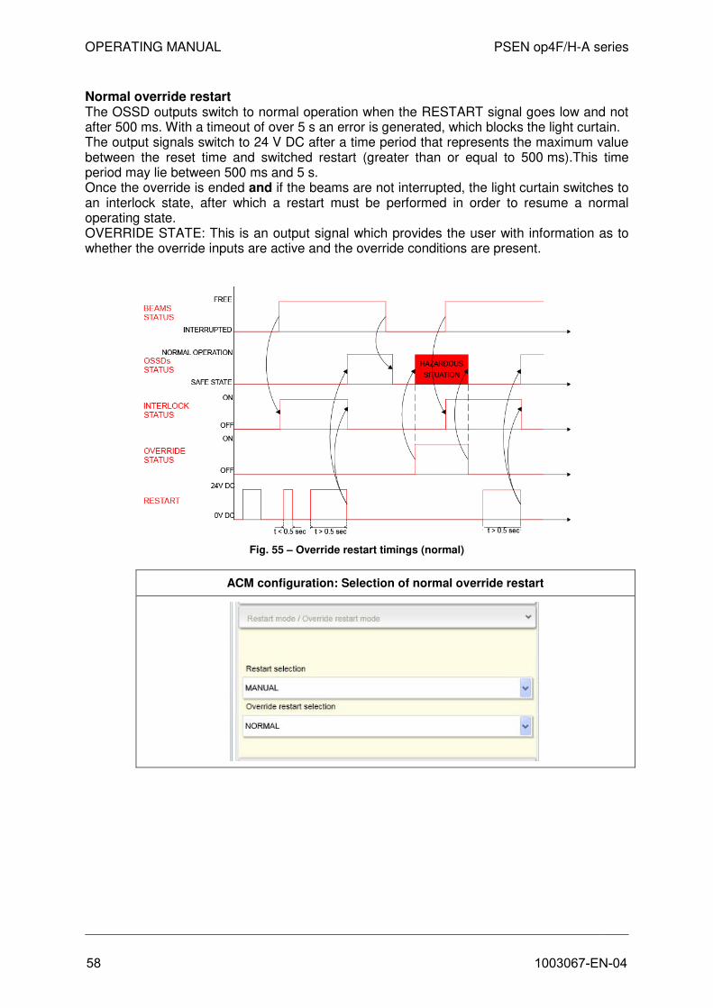
OPERATING MANUAL PSEN op4F/H-A series
Normal override restart The OSSD outputs switch to normal operation when the RESTART signal goes low and not after 500 ms. With a timeout of over 5 s an error is generated, which blocks the light curtain. The output signals switch to 24 V DC after a time period that represents the maximum value between the reset time and switched restart (greater than or equal to 500 ms).This time period may lie between 500 ms and 5 s. Once the override is ended and if the beams are not interrupted, the light curtain switches to an interlock state, after which a restart must be performed in order to resume a normal operating state. OVERRIDE STATE: This is an output signal which provides the user with information as to whether the override inputs are active and the override conditions are present.
Fig. 55 – Override restart timings (normal)
ACM configuration: Selection of normal override restart
58 1003067-EN-04

OPERATING MANUAL PSEN op4F/H-A series
7.9 Blanking Blanking is a function of the safety light curtains, which enables an opaque object to be inserted into the protected field without stopping the machine’s normal operation. Blanking can only be used when certain safety conditions are present and in accordance with a configurable operating logic. The blanking function is particularly useful when the light curtain's protected field will inevitably be within moving parts or material of the machine. So it is possible to maintain the light curtain’s safety outputs on working machinery under normal operating conditions, even if a pre-defined number of beams in the protected area has been interrupted. The blanking function can be selected in two ways: fixed blanking and floating blanking. These two modes can be enabled individually or simultaneously.
Users also have the option to connect a lamp (properties are listed under Chapter 10), which indicates that the blanking function is activated. It is not absolutely necessary to use a lamp for a light curtain that is in blanking mode. The lamp begins to flash in the following circumstances:
− The light curtain is in a fixed blanking mode and the object is being removed from the blanked zone;
− The light curtain is in floating mode with total surveillance and the dimensions of the detected object are changing or the object is being removed from the blanked zone.
To enable all blanking functions, the blanking function can be selected in either BCM or ACM.
BCM configuration: Selection of muting/blanking
PW
R
OS
SD
ED
M
AC
M
LEVEL
Muting LED 3 ON yellow
Blanking LED 3 OFF
ACM configuration: Selection of muting/blanking
1003067-EN-04 59

OPERATING MANUAL PSEN op4F/H-A series
7.9.1 Fixed blanking Fixed blanking enables a certain part of the protected area (e.g. a certain number of beams) to be hidden, while all other beams operate normally. The blanking zone can be achieved using the teach-in process: the user must hold down the 24 V DC N/O teach-in contact (Pin 4 of the 12-pin M12 connector - RX) for at least 3 seconds, while an object interrupts the zone designed for blanking. The blanking zone becomes active as soon as the teach-in contact is without voltage again. If the teach-in contact is depressed for more than a minute, the light curtain is blocked Teach-in can also occur in ACM. The user must place the object/objects within the protected field and then press the teach-in button (“Reduced resolution / Blanking” in the blanking section of the PSENopt Configurator).
ACM configuration: Teach-in
With fixed blanking, the beams from the blanked zone must be interrupted, otherwise the light curtain switches to a SAFE STATE. The tolerance function can be activated by applying a voltage of 24 V DC at the tolerance signal during restart (Pin 9 of the 12-pin M12 connector - RX). If the tolerance is activated, the object can move 1 beam above and below the blanking zone. If the object moves out of the blanking zone by more than 1 beam, the light curtain is blocked due to a blanking tolerance error. The tolerance function is useful if it is only possible for the object to move slightly from its original position. If the light curtain is switched off, the tolerance is lost and it will be necessary to repeat the procedure for setting a tolerance value (described above). If the tolerance is activated, two blanking zones must be separated by at least two beams that have not been blanked. Even if the supply is interrupted or the light curtain is reset, the teach-in configuration is maintained until the next teach-in operation. The user can delete the teach-in configuration by carrying out a new teach-in procedure with a protected area that is object-free. If blanking errors occur, the teach-in configuration will be deleted after the reset. If the user switches from the blanking configuration to the muting configuration and then back to the blanking configuration, all potential teach-in zones that were saved initially will be deleted. Fixed blanking can be combined with floating blanking; at least one synchronisation beam must remain free.
60 1003067-EN-04

OPERATING MANUAL PSEN op4F/H-A series
7.9.2 Fixed blanking with increased tolerance This is fixed blanking with a tolerance on only one side of the blanking zone, so the user must select “top” or “bottom” tolerance. This function is particularly helpful with conveyor belts (which use fixed blanking) with goods transported along them (dimensions within the tolerance). Only fixed blanking zones can be set on the tolerance side. On the other side it’s possible to set fixed as well as floating blanking zones with total surveillance. Only one zone can be set with fixed blanking and increased tolerance. This function can only be set via ACM.
Please note that the actual resolution changes when using this function. Ensure that the minimum distance has to be recalculated and that the installation of the light curtain must be adapted accordingly.
7.9.3 Floating blanking with total surveillance Floating blanking with total surveillance enables the object to move freely within the light curtain’s protected field. The blanked beams must be occupied, which means that the object must stay within the light curtain’s protected field to remain in normal operating mode. This function can only be set via ACM.
7.9.4 Floating blanking with partial surveillance Floating blanking with partial surveillance ensures that the object moves freely within the light curtain’s protected field, although only a certain area in the light curtain is permitted and the hidden beams are adjacent and must not exceed the configured number. This function can only be set via ACM. The diagram below illustrates various blanking configurations.
ACM configuration: Blanking configuration
1003067-EN-04 61
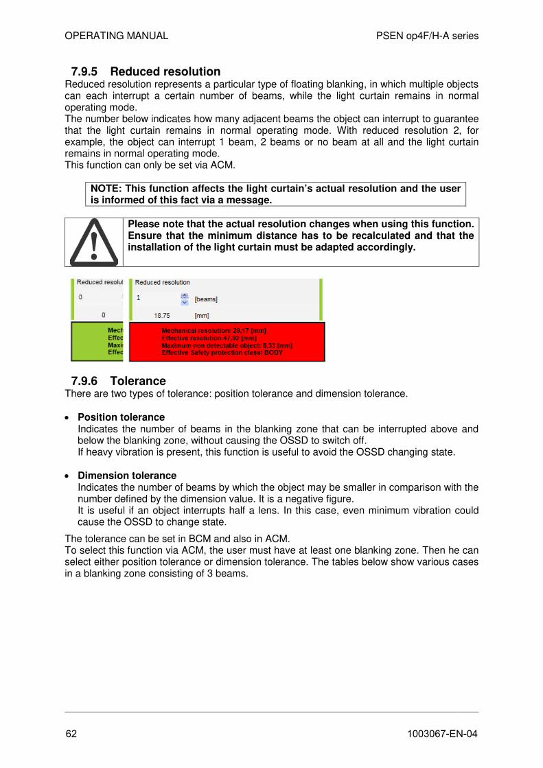
OPERATING MANUAL PSEN op4F/H-A series
7.9.5 Reduced resolution Reduced resolution represents a particular type of floating blanking, in which multiple objects can each interrupt a certain number of beams, while the light curtain remains in normal operating mode. The number below indicates how many adjacent beams the object can interrupt to guarantee that the light curtain remains in normal operating mode. With reduced resolution 2, for example, the object can interrupt 1 beam, 2 beams or no beam at all and the light curtain remains in normal operating mode. This function can only be set via ACM.
NOTE: This function affects the light curtain’s actual resolution and the user is informed of this fact via a message.
Please note that the actual resolution changes when using this function. Ensure that the minimum distance has to be recalculated and that the installation of the light curtain must be adapted accordingly.
7.9.6 Tolerance There are two types of tolerance: position tolerance and dimension tolerance.
• Position toleranceIndicates the number of beams in the blanking zone that can be interrupted above andbelow the blanking zone, without causing the OSSD to switch off.If heavy vibration is present, this function is useful to avoid the OSSD changing state.
• Dimension toleranceIndicates the number of beams by which the object may be smaller in comparison with thenumber defined by the dimension value. It is a negative figure.It is useful if an object interrupts half a lens. In this case, even minimum vibration couldcause the OSSD to change state.
The tolerance can be set in BCM and also in ACM. To select this function via ACM, the user must have at least one blanking zone. Then he can select either position tolerance or dimension tolerance. The tables below show various cases in a blanking zone consisting of 3 beams.
62 1003067-EN-04

OPERATING MANUAL PSEN op4F/H-A series
The existence of the tolerance is indicated by LEDs flashing on the user interface, as shown below.
Tolerance display
PW
R
OS
SD
ED
M
AC
MLEVEL
Tolerance active LED 3 flashes yellow
The tolerance affects the light curtain's actual resolution. Make sure that the new resolution is considered when calculating a new mechanical assembly.
Position tolerance
Dimension tolerance
1003067-EN-04 63

OPERATING MANUAL PSEN op4F/H-A series
7.9.7 Blanking mode in the basic configuration Only a reduced series of configurations can be implemented in basic configuration mode.
BCM configuration: Fixed blanking
PW
R
OS
SD
ED
M
AC
M
LEVEL
1 fixed blanking zone LED 8 ON green
2 fixed blanking zones LED 8 OFF
• 1 fixed blanking zone: only 1 zone can be configured as a blanking zone.
• 2 fixed blanking zones: 2 zones can be configured as blanking zones.
BCM configuration: Floating blanking
PW
R
OS
SD
ED
M
AC
M
LEVEL
Floating blanking disabled LED 6 ON green LED 7 ON green
Floating blanking 1 beam (with partial surveillance)
LED 6 ON green LED 7 OFF
Floating blanking 2 beams (with partial surveillance)
LED 6 OFF LED 7 ON green
Reduced resolution 4 LED 6 OFF LED 7 OFF
• Floating blanking disabled: Floating blanking is not permitted.
• 1 floating blanking beam: The light curtain remains in NORMAL OPERATION if 1 beamor 0 beams are interrupted.
• 2 floating blanking beams: The light curtain remains in NORMAL OPERATION if 2adjacent beams, 1 beam or 0 beams are interrupted.
• Reduced resolution 4: The light curtain switches to a SAFE state if more than 4adjacent beams are interrupted.
64 1003067-EN-04

OPERATING MANUAL PSEN op4F/H-A series
7.9.8 Blanking mode in advanced configuration A maximum of 5 blanking zones (fixed + floating) can be configured in ACM (however, at least one separating beam is required between the zones). The user can select the number of beams via ACM.
• Reduced resolution
ACM configuration
The software calculates the maximum object size (in mm) that the light curtain can detect without triggering a SAFE STATE. The actual resolution of the light curtain changes based on the varying value that is assigned to the parameter N. The safety distance must be calculated based on the actual resolution.
Number of hidden light
beams
Actual resolution of light curtain
14 mm 30 mm 1 23 mm 49 mm
2 33 mm 68 mm
3 42 mm 87 mm
4 51 mm 105 mm
Actual resolution based on the hidden light beams
1003067-EN-04 65

OPERATING MANUAL PSEN op4F/H-A series
• FIXED blankingThe panel on the right shows the settings for the active blanking zone (in the exampleshown below, the active blanking zone is 3 beams in size and is 7 beams from the bottomof the light curtain; no tolerance is set).
• FIXED blanking with increased tolerance (top or bottom )The example shown below illustrates the settings with fixed blanking and an increased toptolerance: only fixed blanking zones are permitted above this zone; fixed blanking zones aswell as zones with total surveillance are permitted below this zone.
66 1003067-EN-04

OPERATING MANUAL PSEN op4F/H-A series
• FLOATING blanking with total surveillanceFloating objects can move up and down, interrupting several beams in the process. Theseobjects can overlap or change positions.The object must be within the protected field at all times and interrupt the number ofconfigured beams with a fixed tolerance of one beam. This is necessary so that a movingobject always interrupts a different number of beams.
• FLOATING blanking with partial surveillanceFloating objects can move up and down, interrupting several beams in the process.These objects can also
− leave the protected field or
− interrupt a lower number of beams than that configured.
Only fixed blanking can be configured around this zone. In these fixed blanking zones,floating objects can overlap and even change position without causing the OSSDs toswitch.
1003067-EN-04 67

OPERATING MANUAL PSEN op4F/H-A series
7.10 Cascading An internal communication bus can be used to cascade several pairs of light curtains with each other. The normal connections at the top and bottom of the light curtain are used with the aid of a cascading cable. The OSSDs are only physically connected to the Master unit. If transmission should fail due to a stuck-at fault or signal degradation, both the Master and Slave units switch to a safe state.
A maximum of three units (Master and two Slaves) can be connected in a cascading configuration: a maximum of 160 beams on models with a resolution of 30 mm and a maximum of 320 beams on models with a resolution of 14 mm. The maximum length of the Master unit is 1800 mm and the maximum length of each Slave unit is 1200 mm. The corresponding cables must be used (see Chapter 14) to ensure that the units are connected correctly in the cascading configuration. An auto-recognition procedure is run on start-up; it automatically synchronizes the topology of the cascading structure and the light curtains.
To enable auto-recognition, the terminator cap (contained in the kit) must be connected to all the light curtains of the cascading system, both in the transmitter and in the receiver unit. Without this connection, a critical communication error will be generated in the Master and Slave units.
7.11 PNP/NPN The PNP/NPN function enables the user to inform the light curtain of the mode in which the OSSDs are connected.
PNP configuration In this configuration, the load is connected between the OSSD output and GND.
In normal operation, the output voltage of the OSSD is 24 V DC
If an opaque object interrupts the beams, the OSSDs switch from 24 V CD to 0 V DC
68 1003067-EN-04

OPERATING MANUAL PSEN op4F/H-A series
Fig. 57 – PNP timings
NPN configuration With this configuration, the load is connected between 24 V DC and the OSSD output switching element. In normal operation, the output voltage of the OSSD is 0 V DC. If an opaque object interrupts the beams, the OSSD status switches from 0 VDC to 24 V.
Fig. 58– NPN connection
1003067-EN-04 69
Fig 56 PNP connection

OPERATING MANUAL PSEN op4F/H-A series
Fig. 59 – NPN timings
7.12 Coding The coding function enables the light curtain to operate normally even if an interference condition occurs with another light curtain. This is particularly true if the transmitter TX of the first light curtain emits beams in the direction of the receiver RX of the second light curtain. To counter this, both light curtains must be configured with different codes (see under Chapter 2.2.2).
• No codeIn this case, no code is selected and the light curtain must be installed at a certaindistance to other light curtains with no code, to avoid potentially dangerous interference.Users who install the light curtains closer than the designated minimum distance mustinstall the TX from the first light curtains on the same side as the RX from the second.
Fig. 60 – No code
70 1003067-EN-04

OPERATING MANUAL PSEN op4F/H-A series
• Code 1 or Code 2If the two light curtains
− are installed at a distance that is lower than the minimum distance permitted foridentical devices
− and has RX on the same side,the user must configure the light curtains with different codes.
NOTE: The configuration performed using the GUI only changes the code on the RX side; for the light curtain to operate correctly, the user must configure the TX side with the same code via BCM.
Fig. 61 – Code 1 and Code 2
If one of the three options (no code, code 1 and code 2) has been selected and beams have been interrupted, the following display appears on the user interface.
Normal operating mode (RX side): beams interrupted
LED Level
PW
R
OS
SD
ED
M
AC
M
LEVEL
No Code LED 5 and 6 OFF
Code 1 LED 5 ON Red, LED 6 OFF
Code 2 LED 5 OFF LED 6 ON Green
Normal operating mode (TX side)
PW
R
TS
T
SR
LR
CODE
No Code LED 5 and 6 OFF
Code 1 LED 5 ON Red, LED 6 OFF
Code 2 LED 5 OFF LED 6 ON Green
1003067-EN-04 71

OPERATING MANUAL PSEN op4F/H-A series
This function can be set in the RX unit as well as the TX unit via BCM. Two codes are available.
BCM configuration: Coding selection (TX and RX)
PW
R
OS
SD
ED
M
AC
MLEVEL
PW
R
TS
T
SR
LR
CODE
No Code LED 2 OFF
Code 1 LED 2 ON Red
Code 2 LED 2 ON Green
ACM configuration: Coding selection
72 1003067-EN-04

OPERATING MANUAL PSEN op4F/H-A series
8 DIAGNOSTICS
8.1 Status of LEDs On the bottom left-hand side of the light curtain 8 LEDs help users to monitor and check the state of the light curtain in alignment mode, in normal mode and when troubleshooting. The LEDs can be used to recognise the configuration that has been set via the pushbuttons. Receiver side (RX):
Meaning of LED
Operating mode of
light curtain Information
LED DISPLAY Suggested action
Alignment
Not aligned
First synchronisation beam linked Last synchronisation beam linked
Minimum signal level
Maximum signal level
Normal operating
mode
Manual restart only
Interlock free beams
User can restart the device by activating the RESTART in normal operating mode.
Interlock interrupted beams
User must clear protected field before activating the RESTART.
Normal operating
mode
OSSD ON (maximum alignment) OSSD OFF Code1 OSSD OFF Code 2
OSSD OFF No Code
Signal level at beams
EDM active
ACM active
ACM ready for configuration
Configuration process running via PC, follow software instructions
1003067-EN-04 73

OPERATING MANUAL PSEN op4F/H-A series
Normal operating
mode
Blanking only
Blanking valid
(OSSD ON)
Blanking invalid
(OSSD OFF)
Blanking zones not observed. Re-configure blanking (teach in if BCM)
Tolerance BCM active
Check the actual resolution for the light curtain and the intended activation of the tolerance function.
Normal operating
mode
Muting only
Muting active
If the OSSDs switch off unintentionally and during active muting, check the partial muting configuration.
Override active
Override status
Activate the override button to bridge OSSDs to light
Override timing error
Check and repeat the override activation sequence. Check the override connections.
Lamp error
Check the lamp connections and check for any potential defects on the lamp.
Error information
OSSD error
Activate RESET. If the problem should persist, please contact Pilz customer services.
Microprocessor error
Activate RESET. If the problem should persist, please contact Pilz customer services.
Lens error
Activate RESET. If the problem should persist, please contact Pilz customer services.
EDM error
Activate RESET. Check the EDM feedback line and the EDM configuration.
Restart error
Check connection RESTART /RESET/REALIGN.
Communication error
Activate RESET. Check the cascading connection and check that the terminator cap is installed correctly.
BCM Configuration error
Perform basic configuration again. If the problem should persist, please contact Pilz customer services.
ACM Configuration error
Perform advanced configuration again. If the problem should persist, please contact customer services.
Critical error
Switch light curtain on/off. If the problem should persist, please contact Pilz customer services.
A critical error cannot be eliminated via a RESET. The light curtain must be switched on and off. If the error should persist, please contact Pilz customer services.
74 1003067-EN-04
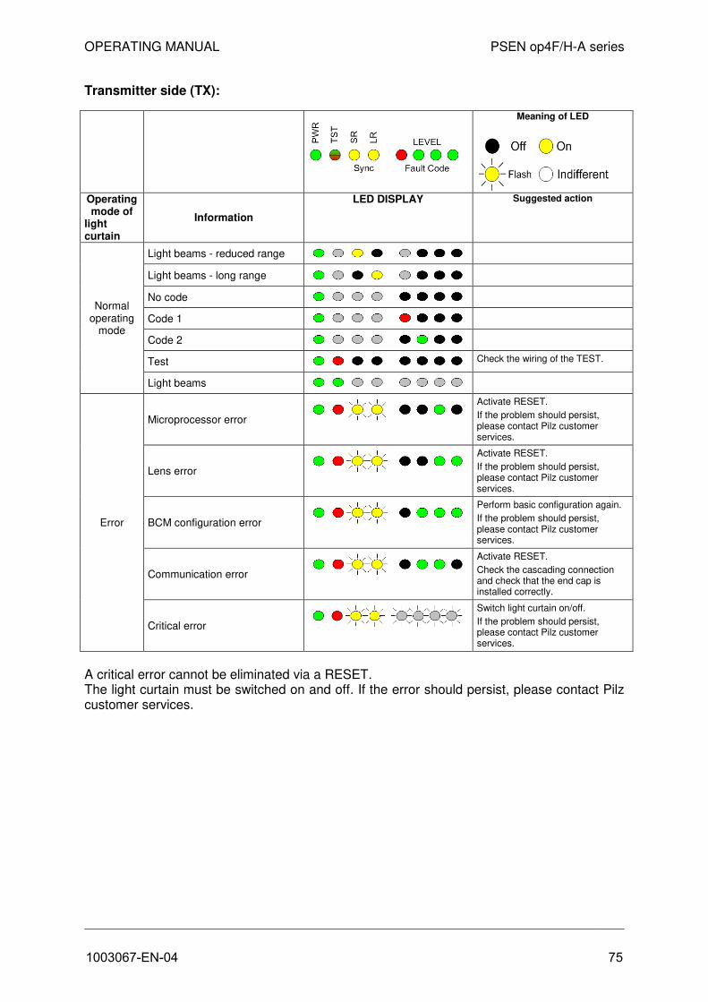
OPERATING MANUAL PSEN op4F/H-A series
Transmitter side (TX):
A critical error cannot be eliminated via a RESET. The light curtain must be switched on and off. If the error should persist, please contact Pilz customer services.
Meaning of LED
Operating mode of
light curtain
Information
LED DISPLAY Suggested action
Normal operating
mode
Light beams - reduced range
Light beams - long range
No code
Code 1
Code 2
Test Check the wiring of the TEST.
Light beams
Error
Microprocessor error
Activate RESET.
If the problem should persist, please contact Pilz customer services.
Lens error
Activate RESET.
If the problem should persist, please contact Pilz customer services.
BCM configuration error
Perform basic configuration again.
If the problem should persist, please contact Pilz customer services.
Communication error
Activate RESET.
Check the cascading connection and check that the end cap is installed correctly.
Critical error
Switch light curtain on/off.
If the problem should persist, please contact Pilz customer services.
1003067-EN-04 75

PSEN OP 4F/H-SERIE BEDIENUNGSANLEITUNG
9 REGULAR CHECKS AND MAINTENANCE
9.1 Regular checks Check the following once a day
• The light curtain is in a safe state (OSSDs off).
− The beams are interrupted across the whole area of the protected field using a test object(test rod) (TP-14 or TP-30) with an appropriate resolution, in accordance with the following diagram.
• Is the light curtain aligned correctly?
− Press gently on the side of the product in both directions. The red LED must not light duringthis process.
• Activate the TEST function on the TX side.
− The OSSD outputs are opened (red LED, OSSD on the RX side, ON and stop of thecontrolled machine).
• The response time to the status of the machine STOP, including the response time of the lightcurtain and machine, is within the limit values defined for calculating the safety distance (seeChapter 2.2).
• The safety distance between the danger zones and the light curtain complies with the detailsspecified in Chapter 2.2.
• Access and exposure of persons between the light curtain and hazardous machine componentsis prevented.
• It is impossible to access the machine’s danger zones from an unprotected side.
• In order to guarantee that the light curtain remains in NORMAL FUNCTION MODE for at least10-15 minutes and, after positioning the specific test object in the protected field, stays in aSAFE STATE for the same time span, there must be no interference from external light sources.
• Check that all additional functions comply by activating them several times under differentoperating conditions.
9.2 Maintenance The safety light curtain in the PSEN op4F/H-A series does not require any special maintenance. The front optical protective surfaces should be cleaned regularly to prevent any reduction in the operating range. Use moist cotton cloths. Do not apply excessive pressure or the surfaces may become tarnished.
The following materials should not be used to clean plastic surfaces or paintwork on the light curtain:
− Alcohol and solvents;
− Woollen cloths or synthetic materials;
− Paper or other abrasive materials.
76 1003067-EN-04

OPERATING MANUAL PSEN op4F/H-A series
10 TECHNICAL DETAILS
Electrical data
Operating voltage: 24 V DC ±20% Current consumption transmitter (TX): Max. 3 W Current consumption receiver (RX): 5 W max (without load) Outputs: 2 PNP or 2 NPN - Short circuit protection: 1.4 A max
- Output current: 0.5 A max. at each output - Output voltage – Status ON: Operating voltage – 1 V min - Output voltage – Status OFF: 0.2 V max. - Capacitive load: 2.2 uF at 24 V DC max Response times: See table below Reset time: 100 ms
Reset time when Sync interrupted: 2 Sec.
Height of protected field: 300..1800 mm
Category: Type 4 (ref. to EN 61496-1) SIL 3 (ref. to EN 61508) SIL 3 (ref. to EN 62061) PL e and Cat. 4 (ref. to EN ISO 13849-1:2008) PFHd [1/h] = 2.64E-09 MTTFd [years] = 444
Auxiliary functions: Test; manual/automatic restart; EDM; reset; muting; blanking; GUI; coding; PNP/NPN connection; cascading
Protection class: Class III (see Ch. 4.1) Current for external lamp: 20 mA min.; 300 mA max.
Connections: - M12 12-pin + M12 5-pin for receiver (mutingmodel)
- M12 12-pin for receiver (blanking model)- M12 5-pin for transmitter (for both models)
Cable length (for supply): 50 m max.
Optical data Transmitter light (λ): Infra-red, LED (950 nm)
Resolution: 14 - 30 mm
Operating range: 0.2…20 m for 30 mm 0.2…7 m for 14 mm
Ambient brightness: IEC-61496-2
Environmental data and mechanical data Operating temperature: 0…+ 50 °C
Storage temperature: - 25…+ 70 °C
Temperature class: T6 Humidity: 15…95 % (non-condensing) Protection type: IP 65 (EN 60529)
Vibration: - Amplitude 0.35 mm,- Frequency 10 … 55 Hz- 20 sweeps per axis,- 1 octave/min. (EN 60068-2-6)
Max. acceleration: 10 g (EN 60068-2-29)
Housing material: Varnished aluminium (yellow RAL 1003) Front surface material: PMMA
Terminator cap material: PBT Valox 508 (RAL 7021)
Cover material: PC LEXAN
Weight: 1.35 kg per running metre per individual unit
1003067-EN-04 77

OPERATING MANUAL PSEN op4F/H-A series
11 LIST OF AVAILABLE MODELS
Model Protected
field height (mm)
No. of beams
Response time AIC OFF
(ms)
Response time AIC ON
(ms)
Resolution (mm)
PSEN op4F-A-14-030/1 300 32 15 20 14
PSEN op4F-A-14-045/1 450 48 17 25 14 PSEN op4F-A-14-060/1 600 64 19 29 14
PSEN op4F-A-14-075/1 750 80 20 34 14
PSEN op4F-A-14-090/1 900 96 22 38 14
PSEN op4F-A-14-105/1 1050 112 24 43 14
PSEN op4F-A-14-120/1 1200 128 26 47 14
PSEN op4F-A-14-135/1 1350 144 27 52 14 PSEN op4F-A-14-150/1 1500 160 29 56 14
PSEN op4F-A-14-165/1 1650 176 31 61 14
PSEN op4F-A-14-180/1 1800 192 33 65 14
PSEN op4H-A-30-030/1 300 16 13 16 30
PSEN op4H-A-30-045/1 450 24 14 18 30
PSEN op4H-A-30-060/1 600 32 15 20 30
PSEN op4H-A-30-075/1 750 40 16 23 30
PSEN op4H-A-30-090/1 900 48 17 25 30 PSEN op4H-A-30-105/1 1050 56 18 27 30
PSEN op4H-A-30-120/1 1200 64 19 29 30
PSEN op4H-A-30-135/1 1350 72 19 32 30
PSEN op4H-A-30-150/1 1500 80 20 34 30
PSEN op4H-A-30-165/1 1650 88 21 36 30 PSEN op4H-A-30-180/1 1800 96 22 38 30
With the following formulas (and with reference to the response times stated in the tables below), users can calculate the response time of any cascading configurations they create.
AIC OFF (without code)
Tcascade [ms] = Tmaster + Tslave1 + Tslave2 + 7.5
AIC ON (with code)
Tcascade [ms] = Tmaster AIC + Tslave1 AIC + Tslave2 AIC + 7.5
Response time of Master AIC OFF
(ms) Tmaster
Response time of Slave AIC OFF
(ms) Tslave
Response time of Master AIC ON
(ms) Tmaster AIC
Response time of Slave AIC ON
(ms) Tslave AIC
PSEN op4F-A-14-030/1 13.7 13.7 19.1 19.1
PSEN op4F-A-14-045/1 15.4 15.4 23.6 23.6
PSEN op4F-A-14-060/1 17.2 17.2 28.1 28.1
PSEN op4F-A-14-075/1 18.9 18.9 32.6 32.6
PSEN op4F-A-14-090/1 20.7 20.7 37.1 37.1
PSEN op4F-A-14-105/1 22.4 22.4 41.6 41.6
PSEN op4F-A-14-120/1 24.2 24.2 46.0 46
PSEN op4F-A-14-135/1 26.0 - 50.5 -
PSEN op4F-A-14-150/1 27.7 - 55.0 -
PSEN op4F-A-14-165/1 29.5 - 59.5 -
PSEN op4F-A-14-180/1 31.2 - 64.0 -
78 1003067-EN-04

OPERATING MANUAL PSEN op4F/H-A series
Response time of Master AIC OFF
(ms) Tmaster
Response time of Slave AIC OFF
(ms) Tslave
Response time of Master AIC ON
(ms) Tmaster AIC
Response time of Slave AIC ON
(ms) Tslave AIC
PSEN op4H-A-30-030/1 11.9 11.9 14.6 15
PSEN op4H-A-30-045/1 12.8 12.8 16.8 17
PSEN op4H-A-30-060/1 13.7 13.7 19.1 19
PSEN op4H-A-30-075/1 14.5 14.5 21.3 21
PSEN op4H-A-30-090/1 15.4 15.4 23.6 24
PSEN op4H-A-30-105/1 16.3 16.3 25.8 26
PSEN op4H-A-30-120/1 17.2 17.2 28.1 28
PSEN op4H-A-30-135/1 18.0 - 30.3 -
PSEN op4H-A-30-150/1 18.9 - 32.6 -
PSEN op4H-A-30-165/1 19.8 - 34.8 -
PSEN op4H-A-30-180/1 20.7 - 37.1 -
1003067-EN-04 79

ABMESSUNGEN
13
12 DIMENSIONS
Model Lt (mm) L (mm)
PSEN op4F/H-A-xx-030-1 150 306.3
PSEN op4F/H-A-xx-045-1 300 456.3
PSEN op4F/H-A-xx-060-1 450 606.3
PSEN op4F/H-A-xx-075-1 600 756.3
PSEN op4F/H-A-xx-090-1 750 906.3
PSEN op4F/H-A-xx-105-1 900 1056.3
PSEN op4F/H-A-xx-120-1 1050 1206.3
PSEN op4F/H-A-xx-135-1 1200 1356.3
PSEN op4F/H-A-xx-150-1 1350 1506.3
PSEN op4F/H-A-xx-165-1 1500 1656.3
PSEN op4F/H-A-xx-180-1 1650 1806.3
xx = Resolution (14 mm – 30 mm)
80 1003067-EN-04

OPERATING MANUAL PSEN op4F/H-A series
13 FITTINGS
Fastening bracket
Terminator cap (fixed to the light curtain)
1003067-EN-04 81

OPERATING MANUAL PSEN op4F/H-A series
Tool for BCM configuration
When not in use, the tool for the BCM configuration can be slotted into the profile groove or into the upper section of the light curtain.
82 1003067-EN-04
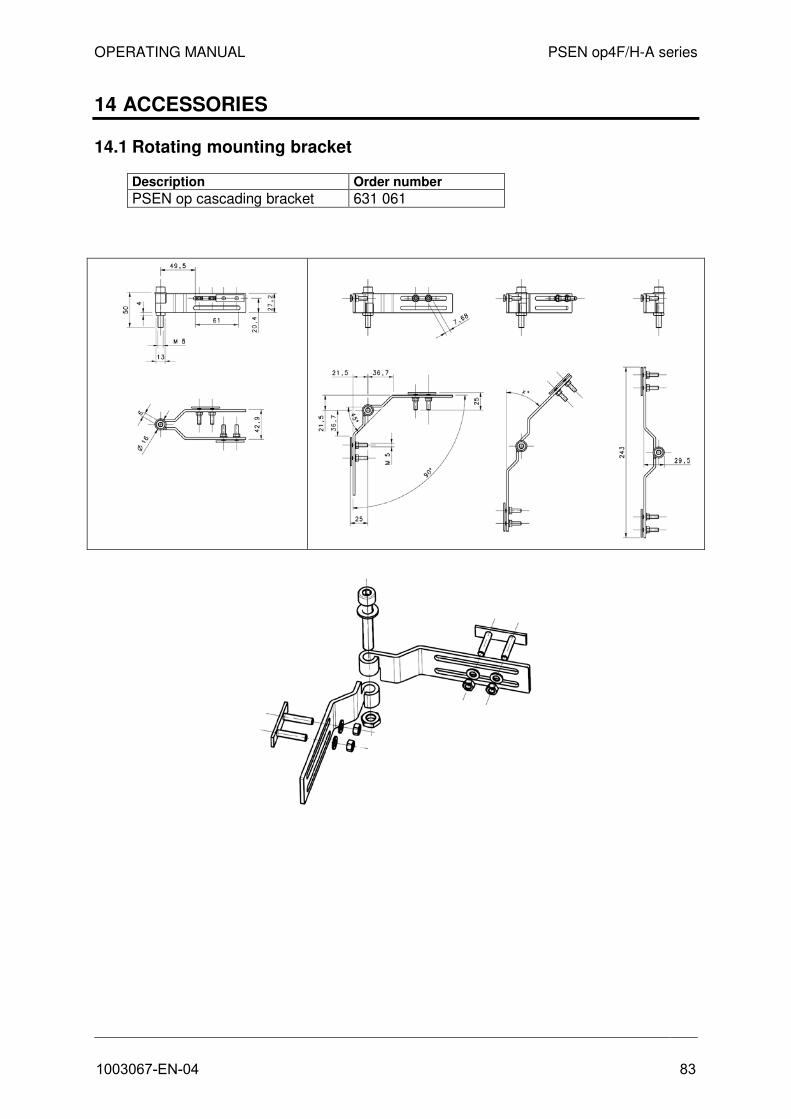
OPERATING MANUAL PSEN op4F/H-A series
14 ACCESSORIES
14.1 Rotating mounting bracket
Description Order number
PSEN op cascading bracket 631 061
1003067-EN-04 83

OPERATING MANUAL PSEN op4F/H-A series
14.2 Cascading cable
Description Order number
PSEN op cascading 0,05 m 631 058 PSEN op cascading 0,5m 631 059 PSEN op cascading 1 m 631 060
Cable length 500 mm for PSEN op cascading 0,5 m
Cable length 1000 mm for PSEN op cascading 1 m
Cable length 50 mm for PSEN op cascading 0,05 m
84 1003067-EN-04

OPERATING MANUAL PSEN op4F/H-A series
14.3 Connection cable
Description Order Number PSEN op pigtail emitter 631 055
Description Order Number PSEN op pigtail receiver b 631 056
Cable length 200 mm
Cable length 200 mm
1003067-EN-04 85

OPERATING MANUAL PSEN op4F/H-A series
Description Order Number PSEN op pigtail receiver m 631 057
14.4 PSEN op Advanced Programming Adapter
Description Order Number PSEN op Advanced Programming Adapter 631 070
Cable length 200 mm
86 1003067-EN-04
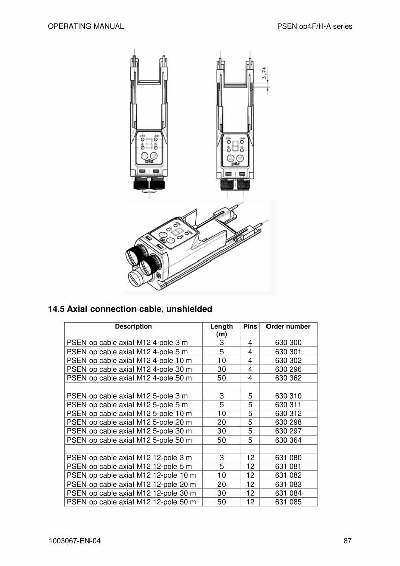
OPERATING MANUAL PSEN op4F/H-A series
14.5 Axial connection cable, unshielded
Description Length (m)
Pins Order number
PSEN op cable axial M12 4-pole 3 m 3 4 630 300 PSEN op cable axial M12 4-pole 5 m 5 4 630 301 PSEN op cable axial M12 4-pole 10 m 10 4 630 302 PSEN op cable axial M12 4-pole 30 m 30 4 630 296 PSEN op cable axial M12 4-pole 50 m 50 4 630 362
PSEN op cable axial M12 5-pole 3 m 3 5 630 310 PSEN op cable axial M12 5-pole 5 m 5 5 630 311 PSEN op cable axial M12 5-pole 10 m 10 5 630 312 PSEN op cable axial M12 5-pole 20 m 20 5 630 298 PSEN op cable axial M12 5-pole 30 m 30 5 630 297 PSEN op cable axial M12 5-pole 50 m 50 5 630 364
PSEN op cable axial M12 12-pole 3 m 3 12 631 080 PSEN op cable axial M12 12-pole 5 m 5 12 631 081 PSEN op cable axial M12 12-pole 10 m 10 12 631 082 PSEN op cable axial M12 12-pole 20 m 20 12 631 083 PSEN op cable axial M12 12-pole 30 m 30 12 631 084 PSEN op cable axial M12 12-pole 50 m 50 12 631 085
1003067-EN-04 87

OPERATING MANUAL PSEN op4F/H-A series
14.6 Ethernet cable for PSEN op Advanced Programming Adapter
Description Length (m) Connection Order number
PSEN op Ethernet cable 1 m 1 M12 / RJ45 631 071 PSEN op Ethernet cable 3 m 3 M12 / RJ45 631 072 PSEN op Ethernet cable 10 m 10 M12 / RJ45 631 073
EC declaration of conformity This product/these products meet the requirements of the directive 2006/42/EC for machinery of the European Parliament and of the Council. The complete EC Declaration of Conformity is available on the Internet at www.pilz.com/downloads.
Representative: Norbert Fröhlich, Pilz GmbH & Co. KG, Felix-Wankel-Str. 2, 73760 Ostfildern, Germany
88 1003067-EN-04

...+
49 7
11 3
409-4
44
sup
po
rt@p
ilz.c
om
Pilz
Gm
bH
& C
o. K
GF
elix
-Wankel-S
traße 2
73760 O
stfi
ldern
, Germ
any
Tele
pho
ne: +
49 7
11 3
409-0
Tele
fax:
+49 7
11 3
409-1
33
E-M
ail:
pilz
.gm
bh@
pilz
.de
Inte
rnet:
ww
w.p
ilz.c
om
Tech
nica
l sup
po
rtIn
many c
ountrie
s w
e a
re
rep
resente
d b
y o
ur s
ub
sid
iarie
s
and
sale
s p
artn
ers
.
Ple
ase re
fer to
our h
om
ep
ag
e
for fu
rther d
eta
ils o
r co
nta
ct o
ur
head
quarte
rs.
InduraNET p®, Pilz®, PIT®, PMCprotego®, PMI®, PNOZ®, Primo®, PSEN®, PSS®, PVIS®, SafetyBUS p®, SafetyEYE®, SafetyNET p®, the spirit of safety® are registered and protected trademarks
of Pilz GmbH & Co. KG in some countries. We would point out that product features may vary from the details stated in this document, depending on the status at the time of publication and the scope
of the equipment. We accept no responsibility for the validity, accuracy and entirety of the text and graphics presented in this information. Please contact our Technical Support if you have any questions.
1003067-EN-04, 2018-12 Printed in Germany© Pilz GmbH & Co. KG, 2011
Tite
lse
ite