Embed Size (px)
Citation preview

PSEG Site ESP Application
Part 3, Environmental Report
Rev. 3 3-i
CHAPTER 3
PLANT DESCRIPTION
TABLE OF CONTENTS
Section Title Page
3.0 INTRODUCTION ..............................................................................................3.0-1
3.1 EXTERNAL APPEARANCE AND PLANT LAYOUT.........................................3.1-1
3.1.1 EXISTING SITE................................................................................................3.1-1 3.1.2 PROPOSED SITE ............................................................................................3.1-2
3.2 REACTOR POWER CONVERSION SYSTEM.................................................3.2-1
3.2.1 REACTOR DESCRIPTION...............................................................................3.2-1 3.2.2 ENGINEERED SAFETY FEATURES ...............................................................3.2-1 3.2.3 POWER CONVERSION SYSTEM ...................................................................3.2-1
3.3 PLANT WATER USE........................................................................................3.3-1
3.3.1 WATER CONSUMPTION .................................................................................3.3-1 3.3.2 WATER TREATMENT ......................................................................................3.3-2
3.4 COOLING SYSTEM .........................................................................................3.4-1
3.4.1 DESCRIPTION AND OPERATIONAL MODES ................................................3.4-1 3.4.1.1 Normal Plant Cooling ....................................................................................3.4-1 3.4.1.2 Service Water System...................................................................................3.4-1 3.4.1.3 Operational Modes........................................................................................3.4-2 3.4.1.3.1 Station Load Factor .......................................................................................3.4-2 3.4.1.3.2 Delaware River Water Temperature ..............................................................3.4-2 3.4.1.3.3 Delaware River Water Level..........................................................................3.4-3 3.4.1.3.4 Anti-Fouling Treatment ..................................................................................3.4-3 3.4.2 COMPONENT DESCRIPTIONS ......................................................................3.4-3 3.4.2.1 Intake System ...............................................................................................3.4-3 3.4.2.2 Discharge System.........................................................................................3.4-4 3.4.2.3 Heat Dissipation System...............................................................................3.4-4
3.5 RADIOACTIVE WASTE MANAGEMENT SYSTEM.........................................3.5-1
3.5.1 LIQUID RADIOACTIVE WASTE MANAGEMENT SYSTEM ............................3.5-1 3.5.2 GASEOUS RADIOACTIVE WASTE MANAGEMENT SYSTEM ......................3.5-2 3.5.3 SOLID RADIOACTIVE WASTE MANAGEMENT SYSTEM .............................3.5-3
PSEG Site ESP Application
Part 3, Environmental Report
TABLE OF CONTENTS (CONTINUED)
Section Title Page
Rev. 3 3-ii
3.6 NON-RADIOACTIVE WASTE SYSTEMS ........................................................3.6-1
3.6.1 EFFLUENTS CONTAINING CHEMICALS OR BIOCIDES...............................3.6-1 3.6.2 SANITARY SYSTEM EFFLUENTS ..................................................................3.6-1 3.6.3 OTHER EFFLUENTS .......................................................................................3.6-2 3.6.3.1 Gaseous Effluents.........................................................................................3.6-2 3.6.3.2 Liquid Effluents..............................................................................................3.6-2 3.6.3.3 Solid Effluents ...............................................................................................3.6-3
3.7 POWER TRANSMISSION SYSTEM................................................................3.7-1
3.7.1 SWITCHYARD INTERFACES ..........................................................................3.7-1 3.7.2 TRANSMISSION SYSTEM ..............................................................................3.7-1 3.7.3 REFERENCES .................................................................................................3.7-2
3.8 TRANSPORTATION OF RADIOACTIVE MATERIALS....................................3.8-1
3.8.1 TRANSPORTATION OF UNIRRADIATED FUEL .............................................3.8-1 3.8.2 TRANSPORTATION OF IRRADIATED FUEL ..................................................3.8-1 3.8.3 TRANSPORTATION OF RADIOACTIVE WASTE ............................................3.8-1
PSEG Site ESP Application
Part 3, Environmental Report
Rev. 3 3-iii
LIST OF TABLES
Number Title
3.3-1 Plant Water Use
3.4-1 Circulating Water System Cooling Tower Design Specifications
3.4-2 SWS/UHS Cooling Tower Design Specifications
PSEG Site ESP Application
Part 3, Environmental Report
Rev. 3 3-iv
LIST OF FIGURES
Number Title
3.1-1 Existing Salem and Hope Creek Site
3.1-2 Site Utilization Plan
3.3-1 Plant Water Use
3.4-1 Conceptual Closed Loop Cooling Water Diagram
3.4-2 Layout View of Intake
3.4-3 Elevation View of Intake
3.4-4 Discharge System Layout
PSEG Site ESP Application
Part 3, Environmental Report
Rev. 3 3-v
ACRONYMS AND ABBREVIATIONS
Acronym Definition
ABWR Advanced Boiling Water Reactor
ac. acre
ALARA as low as reasonably achievable
AP1000 Advanced Passive 1000
BOD5 five-day biochemical oxygen demand
BOP balance of plant
Btu/hr British thermal units per hour
BWR boiling water reactor
CDF confined disposal facility
CFR Code of Federal Regulations
Ci curie
Ci/yr curies per year
COL combined license
CWS circulating water system
dBA A-weighted decibels
DOE U.S. Department of Energy
DOT Department of Transportation
DWDS demineralized water distribution system
EAB Exclusion Area Boundary
ESF engineered safety feature
ESPA early site permit application
fpm feet per minute
fps feet per second
FPS fire protection system
ft. feet
ft3 cubic feet
ft3/yr cubic feet per year
PSEG Site ESP Application
Part 3, Environmental Report
ACRONYMS AND ABBREVIATIONS (CONTINUED)
Rev. 3 3-vi
Acronym Definition
gpd gallons per day
gpm gallons per minute
HCGS Hope Creek Generating Station
hr. hour
km kilometer
kV kilovolt
lbm/hr pound mass per hour
m meter
m3 cubic meter
MBq megabecquerel
mi. mile
MW megawatt
MWd/MTU megawattdays per metric ton of uranium
MTU metric ton of uranium
MWe megawatts electric
MWt megawatts thermal
NAVD North American Vertical Datum (1988)
NJPDES New Jersey Pollutant Discharge Elimination System
NRC U.S. Nuclear Regulatory Commission
PJM PJM Interconnection, LLC
PPE plant parameter envelope
PSWS potable and sanitary water system
PWR pressurized water reactor
RTO regional transmission organization
RTP rated thermal power
SGS Salem Generating Station
SSAR Site Safety Analysis Report
PSEG Site ESP Application
Part 3, Environmental Report
ACRONYMS AND ABBREVIATIONS (CONTINUED)
Rev. 3 3-vii
Acronym Definition
SWS service water system
U-235 uranium-235
UHS ultimate heat sink
USACE U.S. Army Corps of Engineers
US-APWR U.S. Advanced Pressurized Water Reactor
U.S. EPR U.S. Evolutionary Power Reactor
yr year
PSEG Site ESP Application
Part 3, Environmental Report
Rev. 3 3.0-1
CHAPTER 3
PLANT DESCRIPTION 3.0 INTRODUCTION This chapter describes the new plant design based on the plant parameter envelope (PPE) and provides general information about the new plant on the PSEG Site, which includes the existing Salem Generating Station (SGS) and Hope Creek Generating Station (HCGS). The existing 734 acre (ac.) PSEG property is located on the southern part of Artificial Island on the east bank of the Delaware River in Lower Alloways Creek Township, Salem County New Jersey. PSEG is developing an agreement in principle with the U.S. Army Corps of Engineers (USACE) to acquire an additional 85 ac. immediately to the north of Hope Creek Generating Station (HCGS). Therefore, with the land acquisition, the site is 819 ac. The specific timing of land acquisition is not currently known and is subject to further PSEG and USACE actions. However the agreement in principle with the USACE serves to establish the basis for eventual land acquisition and Exclusion Area Boundary (EAB) control, necessary to support the issuance of a future combined license. Subsequent to the agreement in principle with the USACE, PSEG will develop a lease agreement for the USACE confined disposal facility (CDF) land to the north of the PSEG Site, depicted on the Site Utilization Plan for the concrete batch plant and temporary construction/laydown use. At the completion of construction, the leased land will be returned to the USACE, subject to any required long-term EAB control conditions. The specific reactor type has not been selected; however, bounding information from the PPE as presented in this chapter is used as a basis for the evaluation of environmental effects. The reactor types considered are the Advanced Boiling Water Reactor (ABWR), Advanced Passive 1000 (AP1000), U.S. Evolutionary Power Reactor (U.S. EPR), and U.S. Advanced Pressurized Water Reactor (US-APWR). A description of the PPE development and intended use is provided in Site Safety Analysis Report (SSAR) Section 1.3. NUREG-1555, Standard Review Plans for Environmental Reviews for Nuclear Power Plants: Environmental Standard Review Plan, identifies specific items that should be discussed in Chapter 3. However, the new plant designs have not been developed to the point where this information can be provided in the ESPA in all cases. This chapter presents detailed information about the new plant in the following sections:
• External Appearance and Plant Layout (Section 3.1) • Reactor Power Conversion System (Section 3.2) • Plant Water Use (Section 3.3) • Cooling System (Section 3.4) • Radioactive Waste Management System (Section 3.5) • Nonradioactive Waste Management System (Section 3.6) • Power Transmission System (Section 3.7) • Transportation of Radioactive Materials (Section 3.8)
PSEG Site ESP Application
Part 3, Environmental Report
Rev. 3 3.1-1
3.1 EXTERNAL APPEARANCE AND PLANT LAYOUT This section provides a general discussion of the plant layout and appearance. Subsection 3.1.1 describes the existing site, and Subsection 3.1.2 discusses the proposed site. Bounding parameters from the PPE and site-specific characteristics within the SSAR are used to establish conceptual site descriptions. 3.1.1 EXISTING SITE The existing site is located on the southern part of Artificial Island on the east bank of the Delaware River in Lower Alloways Creek Township, Salem County, NJ. The site is 15 miles (mi.) south of the Delaware Memorial Bridge, 18 mi. south of Wilmington, DE, 30 mi. southwest of Philadelphia, Pennsylvania, and 7-1/2 mi. southwest of Salem, NJ. Artificial Island was created, beginning early in the twentieth century, when the USACE began disposing of hydraulic dredge spoils within a progressively enlarged diked area established around a natural bar that projected into the river. The PSEG Site is generally developed. Surrounding habitats can best be characterized as tidal marsh and grassland. The population density of the area surrounding the site is low, and land use is primarily agricultural. The existing site consists of SGS and HCGS. Figure 3.1-1 provides an aerial photograph of the existing site. SGS consists of two pressurized water reactors (PWR) each with a rated power level of 3459 megawatts thermal (MWt) generating capacity. Unit 1 began producing electricity in 1976. Unit 2 began producing electricity in 1980. HCGS is located just north of SGS. HCGS is a single 3840 MWt boiling water reactor (BWR) nuclear plant. The plant was originally designed as a two-unit plant, but during the construction phase the project was scaled back to one unit. HCGS began operation in 1986. The combined SGS and HCGS site occupies 734 ac. The minimum distance from the SGS reactor containment buildings to the nearest exclusion area boundary formed by land is 1270 meters (m) (4166 feet [ft.]). The minimum distance from the HCGS accident release point to the nearest exclusion area boundary formed by land is 900 m (2953 ft.). Both SGS units have steel-lined concrete containment vessels consisting of a reinforced concrete cylindrical wall, a hemispherical dome, and a reinforced concrete base. Supporting structures include a common auxiliary building, service building, turbine generator building, administration building, circulating and service water intake structures, station switchyard, and separate fuel handling buildings for each unit. The HCGS primary containment is a steel shell enclosed in reinforced concrete, and interconnected to a torus type steel suppression chamber. Supporting structures for HCGS include an auxiliary building, turbine building, administration building and warehouse, service water intake structure, switchyard, and natural draft cooling tower.
PSEG Site ESP Application
Part 3, Environmental Report
Rev. 3 3.1-2
3.1.2 PROPOSED SITE Building structures and site arrangement will be designed and constructed in a manner that is both functional and aesthetically consistent, to the degree practical, with the existing site architecture. The new plant location is north of the existing HCGS plant. The new plant requires 225 ac. of permanent land impact as delineated in Figure 3.1-2 and the PPE in Section 1.3 of the SSAR. As discussed in Section 3.0, PSEG is developing an agreement with the USACE to acquire an additional 85 ac. immediately to the north of the current PSEG property line. Therefore, with the land acquisition, the site will be 819 ac. The new plant location and layout on the PSEG Site is shown on the Site Utilization Plan in Figure 3.1-2. The EAB minimum distance of 600 m (1968.5 ft.), is measured from the perimeter of the power block envelope. The new plant site center and the EAB, are shown on the Site Utilization Plan. An architectural rendering will be provided during the combined license (COL) application phase following the selection of a reactor technology. The Site Utilization Plan is prepared by first establishing site layouts for each of the four reactor technology configurations considered for the PSEG Site. The primary power generation areas (power block area, switchyard, cooling tower area, etc.) are located in the same general area on the PSEG Site for each layout considered. Once the layouts are established, the bounding footprint for each specific area (e.g., power block area) is developed by determining the maximum east/west and north/south dimensions. For example, to define the power block area, the east/west dimension of the U.S. EPR and north/south dimension of the dual unit AP1000 are used to establish the power block rectangle area. This approach provides a bounding and conservative estimate of overall land usage on the PSEG Site. Permanent land impact is indicated on the Site Utilization Plan as a cross-hatched area. The land used during construction is indicated as diagonal hatching. The specific areas used for permanent and construction support features are not defined until after a reactor technology is selected, but will be within the overall established Site Utilization Plan boundary. The possible designs are conventional-style plants, based on single-unit or dual-unit construction, with individual turbine and reactor buildings for each unit. The AP1000 is a dual-unit plant while the ABWR, U.S. EPR, and US-APWR are single-unit plants. The power block structure height varies depending upon the reactor design chosen. The bounding structure height (excluding any cooling towers) from finished grade to the top of the tallest power block structure is 234 ft. (SSAR Table 1.3-1, Item 1.1.1). In general, buildings are constructed with concrete, metal with metal siding, or wood with metal, vinyl, or other aesthetically acceptable siding. The new plant circulating water system (CWS) includes one or two natural draft, mechanical draft or fan-assisted natural draft wet cooling towers. The new plant also includes smaller mechanical draft cooling towers for service water system cooling. The Delaware River is used for make-up water for the cooling water systems. The new river intake and discharge structures are described in Section 3.4.
PSEG Site ESP Application
Part 3, Environmental Report
Rev. 3 3.1-3
Existing infrastructure will be modified to integrate the new unit(s) with the existing units; however, none of the existing units’ structures or facilities that directly support power generation are shared or modified. As described in Section 3.7, depending on the reactor technology selected, up to two new switchyards are required for the new plant, and the existing on-site transmission lines will be modified as required to incorporate the new generation capacity into the electric grid. One new off-site transmission line may be required depending on future studies and transmission improvement projects by the Regional Transmission Organization – PJM Interconnection, LLC (PJM). The existing security perimeter will be expanded to include the new plant. The existing sewage treatment facility, training, administrative buildings, warehouses, and other support facilities will be used, expanded, or replaced, to support the new plant, based on economic and operational considerations. During construction, the laydown area and temporary construction support facilities require 205 ac. (SSAR Table 1.3-1, Item 18.2). After new plant construction is complete, areas used for construction support are restored where appropriate to match the overall site appearance or used for other necessary site or industrial support purposes. These areas include equipment laydown and module fabrication areas, batch plant area, areas around completed structures, and construction parking.
PSEG Site ESP Application
Part 3, Environmental Report
Rev. 3 3.2-1
3.2 REACTOR POWER CONVERSION SYSTEM This section provides a general discussion of the reactor, engineered safety features, and the power conversion system. Reactor-specific design parameters, such as fuel assembly description, core fuel capacity, and condenser total heat transfer area will be provided during the COL application phase following reactor technology selection. Bounding parameters from the PPE and site-specific characteristics within the SSAR are used to establish conceptual reactor descriptions. 3.2.1 REACTOR DESCRIPTION The four reactor types considered for the new plant are the ABWR, the AP1000, the U.S. EPR, and the US-APWR. The AP1000 plant consists of two units and associated turbines and power conversion equipment, and the ABWR, U.S. EPR, and US-APWR consist of one unit and associated turbine and power conversion equipment. The ABWR is a boiling water reactor (BWR), and the AP1000, U.S. EPR, and US-APWR are pressurized water reactors (PWR). The design life for a new facility is 60 years (SSAR Table 1.3-1, Item 17.4), and the initial licensed operating life is 40 years based on the Atomic Energy Act and current regulations. The rated thermal power (RTP) of 4590 MWt is the bounding RTP for one unit and 6800 MWt for two units (SSAR Table 1.3-1, Item 19.11). The approximate gross and net electrical output for one unit is 1710 MWe and 1600 MWe, respectively, for the bounding design. The bounding design gross and net electrical output for two units is approximately 2400 MWe and approximately 2200 MWe, respectively. All proposed reactor designs use uranium as their fissile material. The maximum uranium enrichment is five weight percent of uranium-235 (U-235) for the initial fuel load (SSAR Table 1.3-1, Item 19.7). The maximum average assembly discharge burnup is 54,200 megawattdays per metric ton of uranium (MWd/MTU) (SSAR Table 1.3-1, Item 19.8). The peak fuel rod burnup is 62,000 MWd/MTU (SSAR Table 1.3-1, Item 19.9). As discussed in Subsection 5.7.2, these values are within acceptable NRC limits. 3.2.2 ENGINEERED SAFETY FEATURES The proposed reactor designs employ active and/or passive types of engineered safety features (ESF) systems. Active systems rely on active components, such as pumps, to move coolant to the needed locations, while passive systems use gravity and thermal convection to achieve equivalent results. Active systems are typically powered by redundant power sources, such as emergency diesel generators or gas turbine generators. Passive systems use gravity to move coolant, and valves are typically actuated by safety-related dc power. The selected design relies on an ultimate heat sink (UHS) to remove heat from safety-related systems and discharge it to the atmosphere. 3.2.3 POWER CONVERSION SYSTEM The power conversion system for each of the advanced reactor designs under consideration uses a steam turbine to generate power by converting the reactor heat to mechanical energy. The turbines reject exhaust heat to the normal plant cooling water system. The tube material for the condenser or turbine exhaust cooling heat exchangers has not been selected.
PSEG Site ESP Application
Part 3, Environmental Report
Rev. 3 3.3-1
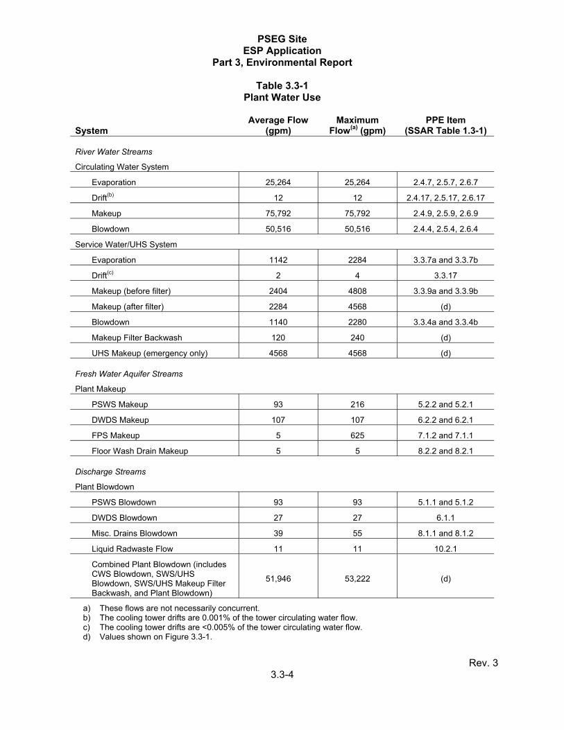
3.3 PLANT WATER USE Water is required to support the new facility during construction and operation, including the CWS, cooling water systems for plant auxiliary components (e.g., the service water system [SWS]), and makeup for the UHS cooling system. The majority of the water is withdrawn from the Delaware River via an intake structure. The bounding CWS flows were determined for site-specific Delaware River water quality and PSEG Site meteorological conditions, and the bounding SWS flows are modified for site-specific river water quality. The fresh water aquifer supplies water for general site purposes including the potable and sanitary water system (PSWS), demineralized water distribution system (DWDS), fire protection system (FPS), and other miscellaneous systems. Subsection 3.3.1 discusses water consumption and discharge by the various cooling water and consumptive water systems, including the expected monthly average and maximum water makeup and discharge flow. Monthly water consumption and water consumption by plant operating status will be provided during the COL application phase following the reactor technology selection. Water availability during periods of drought is discussed in Chapter 5. Subsection 3.3.2 discusses possible treatment methods for water used in the plant and discharged back to the receiving water body. Bounding parameters from the PPE and site-specific characteristics within the SSAR are used to establish conceptual water consumption and water treatment descriptions. 3.3.1 WATER CONSUMPTION The average and maximum water consumption and discharge by the various cooling and water systems is given in Table 3.3-1. This includes maximum and average makeup water flow rates, evaporation rates, drift rates, and blowdown rates for the CWS and SWS; and water supply for the PSWS, DWDS, and FPS. Also included is the discharge flow rate for applicable systems, including miscellaneous drains and liquid radwaste. The average values are the expected limiting values for normal plant operation and the maximum values are those expected for upset or abnormal conditions. The makeup water supply source for the CWS and the SWS/UHS is the Delaware River. Depending on the reactor technology, the UHS may not require a safety-related makeup system or an active safety-related makeup system (AP1000). For the PSWS, DWDS, FPS, and other miscellaneous systems, plant makeup flows are from an on-site freshwater aquifer. The blowdown and discharge water flow is discharged to the Delaware River. Figure 3.3-1 provides a water balance diagram. The total intake from the Delaware River is 78,196 gallons per minute (gpm) (average) and 80,600 gpm (maximum). The total intake from the fresh water aquifer is 210 gpm (average) and 953 gpm (maximum). The CWS and SWS/UHS cooling towers lose water from evaporation, blowdown, and drift. Evaporation, blowdown, and drift estimates for the CWS and SWS/UHS cooling towers are shown in Table 3.3-1. Cooling tower performance curves have not yet been generated, thus a single design point is used to determine CWS parameters. The normal operating design point for the cooling tower is based on a one percent maximum annual non-coincident wet bulb temperature of 76.6°F. No seasonal variability is evaluated in the water consumption values presented. Seasonal variability in wet and dry bulb temperature and relative humidity results in changes to cold water temperature, system flow rates and, ultimately, evaporation rates from the cooling tower. Historically, the natural draft cooling tower that provides heat dissipation for the HCGS CWS produces higher evaporation rates in the summer months than the winter
PSEG Site ESP Application
Part 3, Environmental Report
Rev. 3 3.3-2
months. The design point noted above is representative of a one percent exceedance summer condition at the PSEG Site. As such, the normal operating design values presented for water use at the new plant are conservative when considered from an annual use perspective. The combined plant blowdown consists of CWS blowdown, SWS/UHS blowdown, PSWS blowdown, DWDS blowdown, miscellaneous drains blowdown, liquid radwaste blowdown, and SWS/UHS makeup filter backwash. The combined plant blowdown flows discharge into the Delaware River at a flowrate of 51,946 gpm (average) and 53,222 gpm (maximum). The CWS functions as the heat sink for normal plant processes and is essential to power generation. It provides a continuous supply of cooling water from the normal plant heat sink to the main condensers to remove the heat rejected by the turbine cycle. The main condenser receives exhaust steam from the turbines and cooled water is pumped from the cooling tower through the main condenser and back to the cooling tower, where heat is rejected to the atmosphere by evaporation. The CWS also accommodates heat loads associated with turbine auxiliary equipment. For those plant designs that employ an active safety-related SWS and UHS cooling towers (ABWR, US-APWR, U.S. EPR), the SWS provides essential cooling to safety-related equipment and may also cool nonsafety-related auxiliary components used for normal plant operation. It removes heat from plant components by providing cooling water flow during normal operation, during safe shutdown of the reactor and following a design basis accident. Cooling water from the UHS cooling towers is provided to the component cooling water system heat exchangers, emergency diesel generator heat exchangers and pump room coolers that are necessary for normal safe shutdown and cooldown, anticipated operational events, and accident conditions. The AP1000 design does not require an active external safety-related UHS system to reach safe shutdown. It employs a nonsafety-related SWS to accommodate plant heat loads. Additional plant systems require freshwater. The PSWS supplies water needed for plant operation including potable water, sanitary water, and miscellaneous systems. The DWDS supplies makeup water of reactor coolant quality and treated water for other station operating requirements, including reactor coolant makeup. The FPS supplies water to the wet system type fire suppression systems. The plant water use during construction activities requires freshwater for potable and sanitary use, concrete mixing and curing, and dust control. The total freshwater requirement for construction is 171,932 gallons per day (gpd) or 119 gpm. Of this, the sanitary discharge is 123,000 gpd or 85 gpm. The remainder of the supply is consumed. These construction flows are bounded by the higher total freshwater requirements and potable and sanitary flows during operation. 3.3.2 WATER TREATMENT A description of expected water treatment methods and associated chemical use is described below. Detailed descriptions of these processes and points of injection will be provided during the COL application phase following the selection of a reactor technology. Treatment systems are required for systems supplied by surface water and groundwater, including circulating water makeup, reactor water makeup, service water makeup, condensate,

PSEG Site ESP Application
Part 3, Environmental Report
Rev. 3 3.3-3
potable water, radwaste, and fire protection. The majority of the water is withdrawn from the Delaware River via the intake structure. The intake structure is located at River Mile 52 and is situated in the tidal estuary zone of the Delaware River where it is subject to tidal saltwater intrusion and at the turbidity maxima on the Delaware River. The water is hard and brackish with elevated levels of total dissolved solids and chlorides, elevated levels of both calcium and magnesium, and moderately high suspended solids levels. The source of raw water makeup for the CWS is the Delaware River. Sulfuric acid is used to control calcite scale as required and acid addition maintains a slightly alkaline pH level. This is typical when using tidal estuary water makeup and is consistent with the operational experience at the adjacent HCGS. The combination of low cycles of concentration and acid addition is used so that other scale inhibitors are not anticipated. Chlorination controls microbial growth in the piping and condenser to prevent biofouling and microbiological deposits. Sodium hypochlorite solution is used to control biofouling and is limited by New Jersey Pollutant Discharge Elimination System (NJPDES) permit requirements. Dechlorination of CWS cooling tower blowdown may be required by the NJPDES permit. A sodium bisulfite solution or equivalent is injected as necessary to react with residual chlorine prior to discharge. The source of raw water makeup for the SWS/UHS is the Delaware River. The river water is treated to remove suspended solids by settling in clarifiers. The influent is coagulated and flocculated with polyelectrolyte addition to increase sedimentation rates and improve effluent quality. Settled sludge is dewatered for disposal using mechanical dewatering facilities or in a managed impoundment. Media filters, downstream of the clarifiers, and filter backwash may be used to provide additional suspended solids removal. More comprehensive chemical treatment is provided for the SWS/UHS. The river water requires control of calcite scale and control of iron and sediment deposition. Treatment chemicals include sulfuric acid, an additional blended deposit control agent, and an oxidizing biocide. Sulfuric acid is used for pH reduction to aid in calcium carbonate scale control. A deposit control agent is used to control calcium carbonate scaling, to protect against calcium phosphate scaling, and to control silt and iron deposition. Sodium hypochlorite solution is used to control biofouling. Dechlorination of SWS/UHS cooling tower blowdown may be required by the NJPDES permit. A sodium bisulfite solution or equivalent is injected as necessary to react with residual chlorine prior to discharge. The source for plant makeup flows to the PSWS, DWDS, FPS, and other miscellaneous systems is the on-site freshwater aquifer. Makeup flows to the PSWS and FPS are not treated. Chlorination is provided for the PSWS. The DWDS makeup flow uses a demineralization treatment system such as a dedicated reverse osmosis system to reduce solids, salts, organics, and colloids in the treated water.
PSEG Site ESP Application
Part 3, Environmental Report
Rev. 3 3.3-4
Table 3.3-1 Plant Water Use
System Average Flow
(gpm) Maximum
Flow(a) (gpm) PPE Item
(SSAR Table 1.3-1)
River Water Streams
Circulating Water System
Evaporation 25,264 25,264 2.4.7, 2.5.7, 2.6.7
Drift(b) 12 12 2.4.17, 2.5.17, 2.6.17
Makeup 75,792 75,792 2.4.9, 2.5.9, 2.6.9
Blowdown 50,516 50,516 2.4.4, 2.5.4, 2.6.4
Service Water/UHS System
Evaporation 1142 2284 3.3.7a and 3.3.7b
Drift(c) 2 4 3.3.17
Makeup (before filter) 2404 4808 3.3.9a and 3.3.9b
Makeup (after filter) 2284 4568 (d)
Blowdown 1140 2280 3.3.4a and 3.3.4b
Makeup Filter Backwash 120 240 (d)
UHS Makeup (emergency only) 4568 4568 (d)
Fresh Water Aquifer Streams
Plant Makeup
PSWS Makeup 93 216 5.2.2 and 5.2.1
DWDS Makeup 107 107 6.2.2 and 6.2.1
FPS Makeup 5 625 7.1.2 and 7.1.1
Floor Wash Drain Makeup 5 5 8.2.2 and 8.2.1
Discharge Streams
Plant Blowdown
PSWS Blowdown 93 93 5.1.1 and 5.1.2
DWDS Blowdown 27 27 6.1.1
Misc. Drains Blowdown 39 55 8.1.1 and 8.1.2
Liquid Radwaste Flow 11 11 10.2.1
Combined Plant Blowdown (includes CWS Blowdown, SWS/UHS Blowdown, SWS/UHS Makeup Filter Backwash, and Plant Blowdown)
51,946 53,222 (d)
a) These flows are not necessarily concurrent. b) The cooling tower drifts are 0.001% of the tower circulating water flow. c) The cooling tower drifts are <0.005% of the tower circulating water flow. d) Values shown on Figure 3.3-1.
PSEG Site ESP Application
Part 3, Environmental Report
Rev. 3 3.4-1
3.4 COOLING SYSTEM This section provides a general discussion of the cooling water system. The plant cooling system and the anticipated cooling system modes of operation are described in Subsection 3.4.1. Design data and performance characteristics for the cooling system components are presented in Subsection 3.4.2. Bounding parameters from the PPE and site-specific characteristics within the SSAR are used to establish conceptual cooling system descriptions. 3.4.1 DESCRIPTION AND OPERATIONAL MODES 3.4.1.1 Normal Plant Cooling The primary heat dissipation system is the CWS. The CWS is essential to power generation as it provides a continuous supply of cooling water to the main condenser for condensing turbine exhaust steam and cooling for other turbine auxiliaries, depending on the reactor technology. The CWS transfers this rejected heat to the environment by means of cooling towers that cool the water to an acceptable level through evaporation and subsequently returns it to the cooling tower basin (normal heat sink). The closed loop CWS is composed of pumps, a water basin, and wet cooling towers. Circulating water flowing through the tube bundles of the main condenser absorbs heat from turbine exhaust steam on the condenser shell side. The bounding CWS configuration for the new plant circulates 1,200,000 gpm (SSAR Table 1.3-1, Item 2.4.12) of water through the CWS by circulating water pumps located in the cooling tower basin pump house. The CWS is able to dissipate up to 1.508E10 British thermal units per hour (Btu/hr) of waste heat from the new plant main condensers and other turbine auxiliaries (SSAR Table 1.3-1, Item 2.3.2). The new plant cooling tower design uses either mechanical draft, natural draft, or fan-assisted natural draft wet cooling towers. Figure 3.1-2 shows the relationship of the cooling tower(s) location to the rest of the new plant. The towers use evaporative cooling to transfer up to 1.508E10 Btu/hr of heat to the atmosphere (SSAR Table 1.3-1, Items 2.4.13, 2.5.13, and 2.6.13). Subsection 3.4.2.3 provides further discussion of the CWS cooling tower operation. Cooling tower alternatives are addressed in Chapter 9. A conceptual closed loop cooling water balance diagram is provided in Figure 3.4-1. 3.4.1.2 Service Water System Waste heat from the balance of plant (BOP) auxiliary equipment and heat exchangers not cooled by the plant CWS are cooled by the plant SWS that dissipates this heat to the atmosphere by evaporation through the SWS/UHS cooling towers. All reactor technologies being considered contain a SWS, which may also perform safety-related functions. The SWS associated with the ABWR, US-APWR, and U.S. EPR performs both safety-related and nonsafety-related functions. The SWS associated with the AP1000 performs only nonsafety-related functions. The active safety-related SWS/UHS (ABWR, US-APWR, and U.S. EPR) supplies cooling water to the reactor cooling systems, structures, and components important to safety that are necessary for plant safe shutdown and cooldown, under normal operation, anticipated
PSEG Site ESP Application
Part 3, Environmental Report
Rev. 3 3.4-2
operational occurrences, and accident conditions. The system is reactor technology specific, but is generally comprised of pumps, heat exchangers, a dedicated water basin, and cooling towers. The heat transferred to the safety-related SWS for rejection to the environment in UHS heat removal devices is 2.06E8 Btu/hr (normal) and 4.72E8 Btu/hr (peak) during cooldown (SSAR Table 1.3-1, Item 3.2.2). Although a reactor technology has not been selected, for bounding purposes, it is assumed that safety-related mechanical draft cooling towers provide the UHS function for the PSEG Site. The UHS heat rejection rate to the atmosphere is 3.95E8 Btu/hr during accident operation (SSAR Table 1.3-1, Item 3.3.13b). Subsection 3.4.2.3 provides further discussion of the UHS cooling towers. The quantity of UHS blowdown is discussed in Section 3.3. The UHS associated with the AP1000 design does not require an active safety-related system to reach safe shutdown. The reactor design employs a passive UHS system using water stored in a tank above the containment structure for safety-related cooling. The passive containment cooling system does not require an active external safety-related UHS system to reach safe shutdown. The tank is filled and maintained filled with demineralized water. In the event of a Loss of Coolant Accident or Main Steam Line Break inside containment, water in the tank is dispersed over the steel containment. The passive containment cooling system has no normal plant operation function. Once filled, the storage tank above containment requires minimal demineralized water for evaporation make-up. 3.4.1.3 Operational Modes The CWS provides cooling during the power operation mode. The dissipation rate to the environment for operating modes other than full-power is less than the bounding values for the full-power operational mode. It is anticipated that the new plant is normally operating at 100 percent of its rated thermal power; therefore, bounding heat rejection rates for the CWS represent both average and maximum flows. The SWS/UHS provides heat removal during all modes of normal operation, power operation, cooldown, refueling, and plant startup. During refueling, the SWS/UHS may also support the spent fuel pool heat load during a full core offload. The power operation mode is 18 or 24 months and requires the most makeup water over its duration. Therefore, all other modes are bounded by the power operation mode. 3.4.1.3.1 Station Load Factor The anticipated maximum load factor for the new plant is 96.3 percent (SSAR Table 1.3-1, Item 17.6); however the final maximum load factor is ultimately influenced by factors such as weather conditions, plant efficiency, operating cycle performance, and outage durations. The annualized load factor is the average percentage of time that a plant is capable of providing power to the grid within a year. On a long-term basis, an average heat load of 1.45E10 Btu/hr (96.3 percent of the new plant’s rated heat load discussed in Subsection 3.4.1.1) is dissipated to the atmosphere. 3.4.1.3.2 Delaware River Water Temperature The range of Delaware River water temperatures near the new plant is discussed in SSAR Chapter 2. The intake structure contains ice mitigation features.
PSEG Site ESP Application
Part 3, Environmental Report
Rev. 3 3.4-3
3.4.1.3.3 Delaware River Water Level Depending on the reactor technology selected, the Delaware River may or may not serve as an active nuclear safety-related makeup water supply for UHS cooling. If a reactor technology is selected that requires a safety-related makeup water supply, then the safety-related makeup pumps and the safety-related portion of the intake structure design will provide for the ability to draw water from the extreme low water level defined in SSAR Chapter 2. The design basis flood level is discussed in SSAR Chapter 2. The safety-related portions of the intake structure will be designed to preclude any water impacts from the design basis floods. 3.4.1.3.4 Anti-Fouling Treatment This description is found in Subsection 3.3.2. 3.4.2 COMPONENT DESCRIPTIONS This section describes the design data and performance characteristics of the cooling system components during the anticipated system operation modes. Bounding values from the PPE are used to describe the intake system, discharge system, and heat dissipation system. 3.4.2.1 Intake System The intake structure is designed to meet the bounding makeup requirements of normal and safety-related (reactor technology dependent) cooling systems by drawing water directly from the Delaware River. Makeup water flow rates drawn into the intake structure are discussed in Section 3.3. The intake structure will be located along the east shoreline of the Delaware River, west of the plant site. This location is 2800 ft. north of the existing HCGS service water intake structure as shown in Figure 3.1-2. The approximate intake structure dimensions are 110 ft. by 200 ft. to meet the requirements of the bounding CWS and SWS/UHS demands for the different reactor technologies under consideration. The forebay for the intake extends into the river and the area in front of the intake structure will be dredged to an elevation of -19 ft. 10 in. NAVD. Figure 3.4-2 shows the plan view of the intake along the river with the bathymetry of the river around the intake. It is assumed that the river bottom will be dredged from the shoreline to the -19 ft. 10 in. NAVD river bottom contour on both sides of the intake to provide sufficient depth for the intake water withdrawal. As shown in Figure 3.4-3, the intake structure design consists of a bar rack at the inlet that prevents debris in the river from entering the intake bays. Debris on the bar rack is mechanically cleared by the trash rake, which can traverse across the track installed above the forebay along the face of the intake structure. A baffle wall in each bay is provided to prevent any floating contaminant from reaching the intake pumps. Stop logs can be inserted in the intake bays for maintenance access. To remove small debris, the intake water passes through traveling water screens. The intake structure bay and intake screens are sized so that the average intake through-screen flow velocity is less than 0.5 fps, as required by Clean Water Act, Section 316(b) Phase I requirements specified in 40 CFR 125.84. In accordance with these rules, this design value is subject to conditions of maximum flow (i.e., all pumps in the bay operating at full capacity) so as
PSEG Site ESP Application
Part 3, Environmental Report
Rev. 3 3.4-4
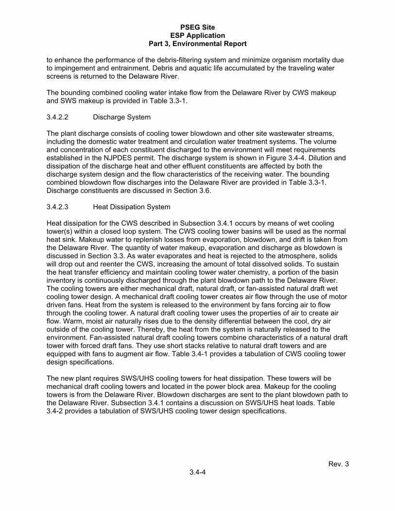
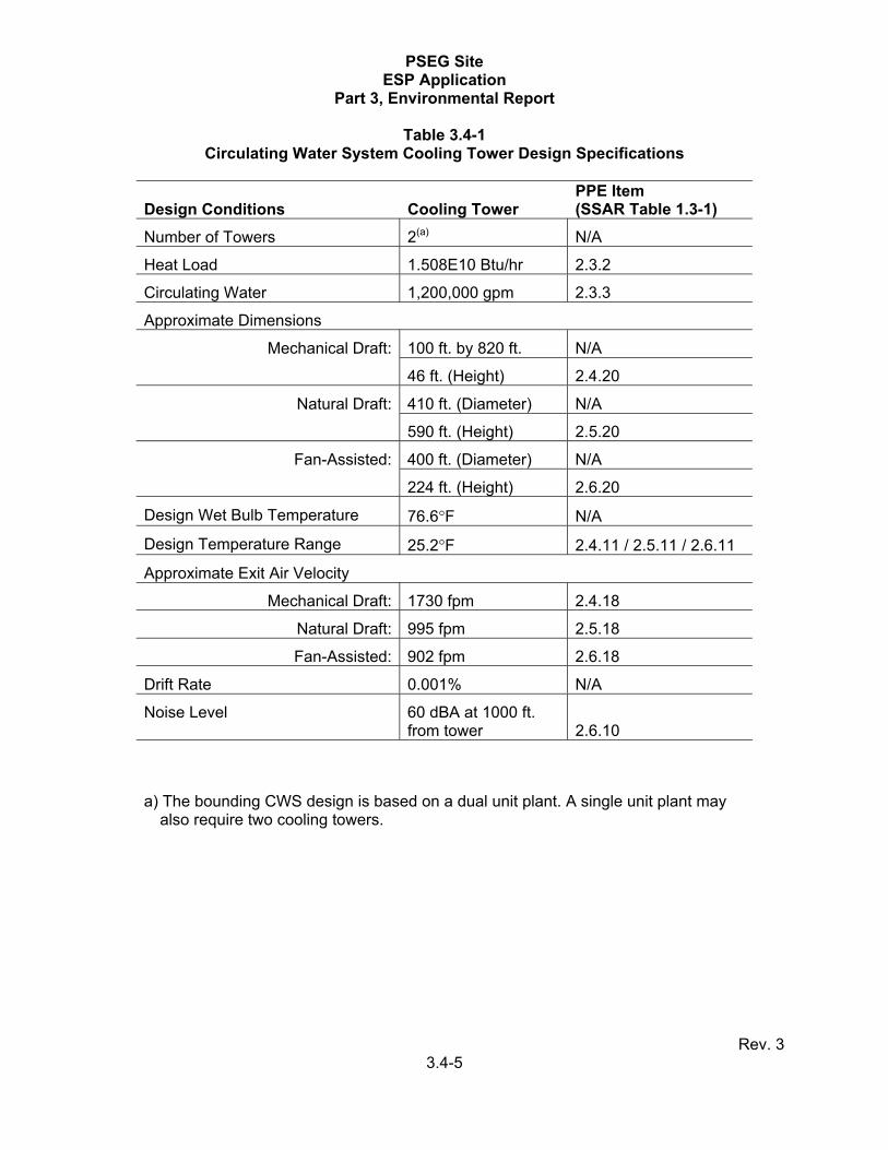
to enhance the performance of the debris-filtering system and minimize organism mortality due to impingement and entrainment. Debris and aquatic life accumulated by the traveling water screens is returned to the Delaware River. The bounding combined cooling water intake flow from the Delaware River by CWS makeup and SWS makeup is provided in Table 3.3-1. 3.4.2.2 Discharge System The plant discharge consists of cooling tower blowdown and other site wastewater streams, including the domestic water treatment and circulation water treatment systems. The volume and concentration of each constituent discharged to the environment will meet requirements established in the NJPDES permit. The discharge system is shown in Figure 3.4-4. Dilution and dissipation of the discharge heat and other effluent constituents are affected by both the discharge system design and the flow characteristics of the receiving water. The bounding combined blowdown flow discharges into the Delaware River are provided in Table 3.3-1. Discharge constituents are discussed in Section 3.6. 3.4.2.3 Heat Dissipation System Heat dissipation for the CWS described in Subsection 3.4.1 occurs by means of wet cooling tower(s) within a closed loop system. The CWS cooling tower basins will be used as the normal heat sink. Makeup water to replenish losses from evaporation, blowdown, and drift is taken from the Delaware River. The quantity of water makeup, evaporation and discharge as blowdown is discussed in Section 3.3. As water evaporates and heat is rejected to the atmosphere, solids will drop out and reenter the CWS, increasing the amount of total dissolved solids. To sustain the heat transfer efficiency and maintain cooling tower water chemistry, a portion of the basin inventory is continuously discharged through the plant blowdown path to the Delaware River. The cooling towers are either mechanical draft, natural draft, or fan-assisted natural draft wet cooling tower design. A mechanical draft cooling tower creates air flow through the use of motor driven fans. Heat from the system is released to the environment by fans forcing air to flow through the cooling tower. A natural draft cooling tower uses the properties of air to create air flow. Warm, moist air naturally rises due to the density differential between the cool, dry air outside of the cooling tower. Thereby, the heat from the system is naturally released to the environment. Fan-assisted natural draft cooling towers combine characteristics of a natural draft tower with forced draft fans. They use short stacks relative to natural draft towers and are equipped with fans to augment air flow. Table 3.4-1 provides a tabulation of CWS cooling tower design specifications. The new plant requires SWS/UHS cooling towers for heat dissipation. These towers will be mechanical draft cooling towers and located in the power block area. Makeup for the cooling towers is from the Delaware River. Blowdown discharges are sent to the plant blowdown path to the Delaware River. Subsection 3.4.1 contains a discussion on SWS/UHS heat loads. Table 3.4-2 provides a tabulation of SWS/UHS cooling tower design specifications.
PSEG Site ESP Application
Part 3, Environmental Report
Rev. 3 3.4-5
Table 3.4-1 Circulating Water System Cooling Tower Design Specifications
Design Conditions Cooling Tower PPE Item (SSAR Table 1.3-1)
Number of Towers 2(a) N/A
Heat Load 1.508E10 Btu/hr 2.3.2
Circulating Water 1,200,000 gpm 2.3.3
Approximate Dimensions
Mechanical Draft: 100 ft. by 820 ft. N/A
46 ft. (Height) 2.4.20
Natural Draft: 410 ft. (Diameter) N/A
590 ft. (Height) 2.5.20
Fan-Assisted: 400 ft. (Diameter) N/A
224 ft. (Height) 2.6.20
Design Wet Bulb Temperature 76.6°F N/A
Design Temperature Range 25.2°F 2.4.11 / 2.5.11 / 2.6.11
Approximate Exit Air Velocity
Mechanical Draft: 1730 fpm 2.4.18
Natural Draft: 995 fpm 2.5.18
Fan-Assisted: 902 fpm 2.6.18
Drift Rate 0.001% N/A
Noise Level 60 dBA at 1000 ft. from tower 2.6.10
a) The bounding CWS design is based on a dual unit plant. A single unit plant may also require two cooling towers.
PSEG Site ESP Application
Part 3, Environmental Report
Rev. 3 3.4-6
Table 3.4-2 SWS/UHS Cooling Tower Design Specifications
Design Conditions Cooling Tower PPE Item (SSAR Table 1.3-1)
Heat Load
Normal: 2.06E8 Btu/hr 3.2.2
Peak: 4.72E8 Btu/hr 3.2.2
Accident: 3.95E8 Btu/hr 3.3.13b
Approximate Dimensions
Cooling Tower Deck Height: 63 ft. 3.3.8a
Exhaust Stack Height: 35 ft. 3.3.8b
Drift 2 gpm 3.3.17
Noise Level 57 dBA at 200 ft. from tower
3.3.10
PSEG Site ESP Application
Part 3, Environmental Report
Rev. 3 3.5-1
3.5 RADIOACTIVE WASTE MANAGEMENT SYSTEM This section provides a general discussion of the new plant radioactive waste management systems. Detailed information regarding the description of the liquid and gaseous radioactive waste management and effluent control systems, instrumentation and process flow diagrams, release points, and sources of waste will be provided during the COL application phase following reactor technology selection. A description of the development and intended use of the PPE is provided in Section 1.3 of the SSAR. Bounding parameters from the PPE and site-specific characteristics within the SSAR are used to establish radioactive waste management system descriptions. Radioisotopes are produced during normal operation of a nuclear power plant, primarily through the processes of fission and activation. The radioactive waste may be liquid, solid, or gaseous. Through leakage or diffusion, fission products may enter the reactor coolant. These radioisotopes may enter the environment from plant systems designed to remove impurities, small leaks in reactor coolant or auxiliary systems, or breaching of systems for maintenance. The quantities of radioactive waste that are projected to be generated and processed and then stored or released annually as liquid or gaseous effluents or as solid waste are provided in this section. Radioactive waste management and effluent control systems are designed to minimize releases from reactor operations to values as low as reasonably achievable (ALARA). These systems are designed to meet the requirements of 10 CFR 20, Standards for Protection Against Radiation, and 10 CFR 50, Domestic Licensing of Production and Utilization Facilities, Appendix I and are maintained in accordance with ALARA principles, protective of the environment, and minimize radiological doses to the public. 3.5.1 LIQUID RADIOACTIVE WASTE MANAGEMENT SYSTEM Liquid radioisotopes are produced during the normal operation of nuclear reactors. The liquid radwaste system is designed to control, collect, process, handle, store, and dispose of liquid radioactive waste generated during normal operation, including anticipated operational occurrences. The system is designed to gather liquids that may leak from radioactive and potentially radioactive sources and store those liquids for further processing. The liquid waste sources include leakage from the reactor coolant system, detergent wastes, cleanup and purification systems, chemical wastes, and other similar sources. These sources and potential sources are identified and collected in systems designed to contain any leakage and return it to the system or transport it to a liquid waste management system collection point for treatment or disposal. The system is designed to store and process the waste to maintain radiation exposure ALARA. After processing, small quantities of radioactive effluents may be released to the environment at release points, typically in the cooling water discharge stream, and are monitored to measure the activity released. The flow rate at the discharge release point of potentially radioactive liquid effluent streams is 11 gpm (SSAR Table 1.3-1, Item 10.2.1). The following sources are considered in calculating the release of radioactivity in liquid effluents from normal operations and anticipated operational occurrences:
PSEG Site ESP Application
Part 3, Environmental Report
Rev. 3 3.5-2
• Processed liquid wastes from the equipment drain subsystems • Processed liquid wastes from the floor drain subsystems • Processed liquid wastes from the chemical waste subsystems • Processed liquid regenerant wastes • Detergent wastes
The estimated bounding annual average activity released to the environment in liquid effluents from a new plant is provided in SSAR Table 1.3-8. Additionally, a bounding annual average release of tritium is 1660 curies per year (Ci/yr) (SSAR Table 1.3-8). 3.5.2 GASEOUS RADIOACTIVE WASTE MANAGEMENT SYSTEM Gaseous radioisotopes are produced during the normal operation of nuclear reactors. The gaseous radwaste system is designed to control, collect, process, store, and dispose of potentially radioactive gases including noble gases, radioactive particulates, tritium, and iodine during normal operation. The system is designed to retain these gases and remove them in a controlled fashion through a gaseous waste collection system, which collects waste from multiple sources and then stores the gas to allow short-lived isotopes to decay. The remaining activity is released to the environment through a waste gas processing system designed to minimize the release to and the impact on the environment through a monitored release point. The system is designed to store and process released waste to maintain radiation exposure ALARA. Some hydrogen and oxygen is generated from the hydrolysis and radiolysis of the coolant water. At sufficiently high concentrations, these gases can form flammable and explosive mixtures. Therefore, applicable streams in the gaseous radwaste system are monitored for both hydrogen and oxygen concentration so a flammable limit is not reached. The gaseous radwaste system maintains hydrogen and oxygen levels through nitrogen dilution or removal by a recombiner. A small fraction of gaseous waste may leak from the plant systems into the plant atmosphere. Monitoring systems are designed to detect and quantify the leakage. These gases are released through the monitored building ventilation system release points, or in some cases, through filtration systems designed to remove particulates and selected isotopes. The ventilation and gaseous radwaste systems’ release points are designed to dilute the waste stream and release the gas at an elevated location. The bounding elevation for the normal release point is ground level for routine operational releases (SSAR Table 1.3-1, Item 9.4.2). The following sources are considered in calculating the release of radioactive materials (noble gases, radioactive particulates, tritium, and iodine) in gaseous effluents from normal operations and anticipated operational occurrences:
• Main condenser offgas system (ABWR plant) • Mechanical vacuum pumps (ABWR plant) • Ventilation exhaust air from the various plant buildings with potentially contaminated
ventilation systems • Waste gas processing and handling systems
PSEG Site ESP Application
Part 3, Environmental Report
Rev. 3 3.5-3
The estimated bounding annual average activity released to the environment in gaseous effluents, is found in SSAR Table 1.3-7. Additionally, a bounding annual average release of tritium is 350 Ci/yr (SSAR Table 1.3-7). 3.5.3 SOLID RADIOACTIVE WASTE MANAGEMENT SYSTEM Solid radioactive wastes are produced during the normal operation of nuclear reactors. Solid radioactive wastes can be either dry or wet solids. The sources are from an operational activity, maintenance, or other functions. The solid radwaste system is designed to receive, collect, and store any solid radioactive wastes prior to their processing and packaging for on-site storage or shipment off-site. The PSEG Site currently has a solid radwaste system in place for the HCGS and SGS. The low-level solid waste storage from the new plant will be coordinated with that from the existing plants. The solid radwaste system is designed to handle the following waste types: dry active waste, spent filter elements, spent resin, spent activated carbon, oil, and sludge. The system is designed to store and process the waste to maintain ALARA radiation exposure. Radiation monitors are used to monitor the area and the waste to ensure that applicable requirements are met. The system design ensures that the solid radioactive wastes are collected, monitored, segregated, stored, and packaged for shipment in a manner that minimizes exposure to plant personnel and the public in accordance with 10 CFR 20 and 10 CFR 50, Appendix I. The bounding annual volume of radioactive solid waste is 16,721.5 cubic feet per year (ft3/yr) (SSAR Table 1.3-1, Item 11.2.3). SSAR Table 1.3-3 provides the bounding annual radionuclide activities from routine plant operations.
PSEG Site ESP Application
Part 3, Environmental Report
Rev. 3 3.6-1
3.6 NON-RADIOACTIVE WASTE SYSTEMS This section provides a general discussion of typical non-radioactive waste streams expected at the new plant, including cooling water and auxiliary boiler blowdown that may contain water-treatment chemicals or biocides, water-treatment wastes, floor and equipment drains, storm water runoff, laboratory waste, trash, hazardous waste, effluents from the sanitary sewer system, and miscellaneous gaseous, liquid and solid effluents. Non-radioactive liquid wastes are collected in the wastewater treatment system. The system is designed to stop the discharge of wastewater upon detection of high radiation in the stream to the discharge point. Detailed information regarding the description of the non-radioactive waste management and effluent control systems, process/instrumentation diagrams, and system process flow diagrams will be provided during the COL application phase following reactor technology selection. Bounding parameters from the PPE and site-specific characteristics within the SSAR are used to establish conceptual non-radioactive waste system descriptions. 3.6.1 EFFLUENTS CONTAINING CHEMICALS OR BIOCIDES Proper plant water chemistry includes the treatment of water used in various secondary systems as described in Subsections 3.3.2 and 3.4.1.3.4. Effluents from these new plant water systems are processed to minimize the release of these treatments, but they may still contain some low-level chemicals and/or biocides. The chemical concentrations within new plant effluent streams are controlled through engineering and operational/administrative controls to meet NJPDES requirements, and requirements and limitations set by appropriate federal, regional, or local regulatory agencies at the time of construction and operation. The following list identifies chemicals that may be present in the permitted discharge from the new plant:
• Sodium hydroxide and sulfuric acid, which are used to regenerate resins (depending on plant design), will be neutralized; resulting effluent will contain sodium and sulfate salts.
• Sulfuric acid for calcite scale control in cooling water systems • Phosphate in cleaning solutions • Biocides used for condenser defouling • Boiler blowdown chemicals • Oil and grease from plant floor drains • Chloride • Total residual oxidants
SSAR Table 1.3-2 provides the estimated concentrations of impurities in the blowdown water. 3.6.2 SANITARY SYSTEM EFFLUENTS This section identifies anticipated volumes of sanitary effluent during the new plant construction and operation, including the nature of sanitary effluents. The sewage treatment system treats the daily flow from the new plant and the existing site. Conceptually, the facility will be a package plant equipped with an extended aeration activated sludge system. Two units, each with a capacity of 70,000 gpd, will be provided. Each unit
PSEG Site ESP Application
Part 3, Environmental Report
Rev. 3 3.6-2
includes an aeration tank and clarifier followed by a chlorine contact chamber. A single surge tank is provided to equalize variations in influent flows to the treatment units. A sludge holding tank is provided for waste sludge. Residuals are disposed off-site in a manner similar to current practices at the existing facility. Performance of the sewage treatment system will conform to NJPDES permit requirements. The sewage treatment system will also be sufficient to treat sanitary wastes during construction. The bounding influent flow to the sanitary treatment system for the new plant is an average of 93 gpm (SSAR Table 1.3-1, Item 5.2.2). This equates to an average daily flow of 134,000 gpd. The bounding influent flow during construction is 123,000 gpd (85 gpm average) based on a peak construction population of 4100 persons (SSAR Table 1.3-1, Item 18.4.1) and a flow of 30 gallons per capita per day. This flow is within the proposed design capacity of the system. New plant effluent discharges are regulated under the provisions of the Clean Water Act and the conditions of discharge, including total suspended solids and five-day biochemical oxygen demand (BOD5), will be specified in the NJPDES permit. The estimated operational normal and maximum effluent flow rate from the sanitary waste water system is 93 gpm (SSAR Table 1.3-1, Item 5.1.1 and 5.1.2). 3.6.3 OTHER EFFLUENTS This section addresses miscellaneous gaseous, liquid, and solid effluents that are non-radioactive including gaseous releases from operation of auxiliary boilers, standby diesel generators, gas turbines, cooling water blowdown, plant and mechanical drain systems, and storm drainage. 3.6.3.1 Gaseous Effluents Non-radioactive gaseous effluents result from the seasonal and intermittent operation of the auxiliary boilers, and from intermittent testing and operation of the standby power system which may be diesel and/or gas turbine generators. These effluents commonly include particulates, sulfur oxides, carbon monoxide, hydrocarbons, and nitrogen oxides. The auxiliary boiler exhausts from an elevation of 150 ft. above grade (SSAR Table 1.3-1, Item 13.1), and the emissions are provided in SSAR Table 1.3-4. The standby diesel generators’ exhaust is at an elevation of 50 ft. above grade (SSAR Table 1.3-1, Item 16.1.2), and the emissions are provided in SSAR Table 1.3-5. The gas-turbines exhaust is at an elevation of 50 ft. above grade (SSAR Table 1.3-1, Item 16.2.2), and the emissions are provided in SSAR Table 1.3-6. Gaseous effluent releases will comply with federal, state, and local emissions standards. 3.6.3.2 Liquid Effluents Non-radioactive liquid effluents that potentially drain to the Delaware River are limited under the NJPDES permit. These liquid effluents are primarily discharges of site storm drainage and other power block discharges, such as oily waste, acid/caustic wastes, and normal waste. Existing site storm drainage outfalls may be modified and new outfalls to the Delaware River may be constructed to accommodate adjusted flow paths, or volumes created by the construction and
PSEG Site ESP Application
Part 3, Environmental Report
Rev. 3 3.6-3
operation of the new plant. Liquid effluents from the power block of the new plant are combined with the cooling tower blowdown and sanitary system effluent, and routed to the common plant outfall that discharges to the Delaware River. The design of the storm water systems for the new plant will comply with relevant federal, state, and local storm water regulations. The overall plant blowdown constituents and concentrations are provided in SSAR Table 1.3-2. 3.6.3.3 Solid Effluents Non-radioactive solid wastes include typical industrial wastes such as metal, wood, and paper, as well as process wastes such as non-radioactive resins and sludge. PSEG is currently a conditionally exempt small-quantity hazardous waste generator, generating less than 100 kilograms/month (220 pounds/month). PSEG maintains the program required of a small-quantity generator and monitors the amount of hazardous waste generated each month. Hazardous waste is disposed of through licensed disposal facilities. Universal waste, such as paint waste, lead-acid batteries, used lamps, and mercury-containing switches, is segregated and disposed of through licensed disposal facilities. Normal station waste (e.g., paper, plastic, glass, river vegetation) is segregated and, as much as possible, processed for recycling. Approximately two-thirds (2/3) of the normal station waste is transferred to recycling vendors, and the remainder either incinerated or land filled. It is anticipated that there will be no change to the method for handling solid wastes created by the new plant.
PSEG Site ESP Application
Part 3, Environmental Report
Rev. 3 3.7-1
3.7 POWER TRANSMISSION SYSTEM The new plant will be located adjacent to the HCGS and SGS. The electric power systems for these plants generate and transmit power into the PJM Interconnection, LLC (PJM) power grid. PJM is a regional transmission organization (RTO) that manages the high-voltage power grid and coordinates the movement of wholesale electricity in a market that serves 13 states and the District of Columbia (Reference 3.7-1). PJM coordinates planning and operation for its members, and with adjacent nonmember utilities and power pools, under a wide range of normal and emergency conditions. 3.7.1 SWITCHYARD INTERFACES HCGS and SGS have separate, dedicated switchyards. Both switchyards operate nominally at 500 kilovolts (kV). The switching station designs at each plant incorporate a breaker-and-a-half scheme for high reliability. A new plant switchyard is required to support new plant operation. The new plant switchyard is electrically integrated with the existing switchyards via a site interposing switchyard to provide 500 kV connections. Electric power generated by the new plant is fed through isolated phase bus to a main transformer bank(s) where it is stepped up to 500 kV and delivered to the new plant switchyard. The bounding land usage required within the PSEG Site for the switchyards is 63 ac. (SSAR Table 1.3-1, Item 15.1.1). The Site Utilization Plan shown in Figure 3.1-2 depicts the relative locations of the switchyards. The configuration of the switchyards is dependent on the reactor technology, number of units, and the approach for integration with the existing HCGS and SGS switchyards. The switchyards require additional support services and structures for grounding, lightning protection, switchyard control power, and area lighting. 3.7.2 TRANSMISSION SYSTEM Presently, there are two 500 kV transmission lines to the HCGS switchyard from off-site, and one 500 kV tie line from HCGS to the SGS switchyard. One off-site line is a 17-mi. tie to the Red Lion Substation, located northwest near Newark, DE, and the other line is a 43-mi. tie to the New Freedom Switching Station, located northeast in Camden County, NJ. All three lines are physically independent sources of off-site power to HCGS. In addition, there are two 500 kV transmission lines to the SGS switchyard from off-site, and one 500 kV tie line from SGS to the HCGS switchyard. One off-site line is a 42-mi. tie to the New Freedom Switching Station, described above. The second off-site line is a 50-mi. tie to the New Freedom Switching Station. During 2008, a new substation (Orchard) was installed along this line, dividing it into two segments. All three lines are physically independent sources of off-site power to SGS and are available for either or both units. Transmission lines meet or exceed design requirements set forth by the National Electrical Safety Code and meet with Lower Delaware Valley 500-kV Transmission Design Criteria. Lines meet the USACE requirements for clearance over flood levels. The existing transmission lines servicing the PSEG Site have adequate thermal capacity to accommodate the additional new plant generation. To support the new plant, one additional off-site transmission line may be required for transient stability purposes. Formal PJM analyses are
PSEG Site ESP Application
Part 3, Environmental Report
Rev. 3 3.7-2
required to fully identify the requisite transmission system upgrades that are necessary to accommodate a new nuclear plant at the PSEG Site. These PJM analyses have not been initiated, but formal entry into the PJM generation queue and commencement of these analyses is anticipated when a reactor technology is selected. PJM will evaluate the additional new plant generation along with the regional transmission system configuration and independent projects in the planning cycle at that time (Reference 3.7-1). As is summarized in Subsection 1.2.5, PSEG completed a conceptual evaluation during development of the ESP application to identify potential transmission requirements associated with the addition of generation at the PSEG Site. This evaluation included the PJM Regional Transmission Expansion Plan, existing operational limits at HCGS and SGS, and other PJM transmission planning inputs. PJM routinely performs analyses of the regional transmission system and forecasts appropriate upgrades to the system as part of its long-term planning cycle. These evaluations are not specific to the addition of new generation at the PSEG Site. In order to capture the potential effects of developing off-site transmission, PSEG analyzed the potential effects of two new off-site macro-corridors during development of the ESP application. Information pertaining to alternative off-site transmission system corridors considered by PSEG is presented in Subsection 9.4.3. PSEG transmission lines and rights-of-way are patrolled about five times each year to ensure that the physical and electrical integrity of transmission line supports, hardware, insulators, and conductors are acceptable for safe and reliable service. This periodic transmission line patrol is conducted by helicopter and ground patrols. Climbing inspections of structures are performed approximately every three years depending on the age of the line. Additional information on maintenance of transmission corridors, electric field effects, induced current hazards, corona noise, and radio/television interference is provided in Section 5.6. 3.7.3 REFERENCES
3.7-1 PJM Interconnection, Website, http://www.pjm.com/ , accessed June 17, 2009.
PSEG Site ESP Application
Part 3, Environmental Report
Rev. 3 3.8-1
3.8 TRANSPORTATION OF RADIOACTIVE MATERIALS This section describes the transportation of unirradiated fuel, irradiated fuel (spent nuclear fuel), and radioactive waste required at the PSEG Site and alternative sites. Subsection 5.7.2 also addresses 10 CFR 51.52, Environmental Effects of Transportation of Fuel and Waste, (a)(1) through (a)(5) regarding use of Table S-4 to characterize both the impacts of radioactive materials transportation and provide an analysis of the radiological impacts from incident-free transportation of these materials. Section 7.4 addresses postulated radiological transportation accidents. 3.8.1 TRANSPORTATION OF UNIRRADIATED FUEL New fuel assemblies are transported to the PSEG Site from a fuel fabrication facility in accordance with Department of Transportation (DOT) (49 CFR Parts 173, Shippers – General Requirements for Shipments and Packagings, 178, Specifications for Packagings, and 397, Transportation of Hazardous Materials; Driving and Parking Rules) and NRC regulations (10 CFR Part 71, Packaging and Transportation of Radioactive Material). The fuel assemblies are shipped by truck to the PSEG Site shortly before they are required. The container designs, shipping procedures, and transportation routing will be in accordance with DOT and NRC regulations and depend on the requirements of the suppliers providing the fuel fabrication services. The truck shipments will not exceed 73,000 pounds as governed by federal or state gross vehicle weight restrictions. 3.8.2 TRANSPORTATION OF IRRADIATED FUEL Spent fuel assemblies are discharged from each unit and will remain in spent fuel pools associated with the new units at least five years while short half-life isotopes decay. The new plant has sufficient spent fuel capacity to ensure that irradiated fuel can be stored for at least five years before being removed from the spent fuel pool. After a sufficient decay period, the fuel will be removed from the pool and packaged in spent fuel shipping/storage casks, licensed in accordance with 10 CFR 72, Licensing Requirements for the Independent Storage of Spent Nuclear Fuel and High-Level Radioactive Waste, and Reactor-Related Greater Than Class C Waste, and transferred either to an independent spent fuel storage installation facility on-site or an off-site disposal facility. Packaging of the fuel for off-site shipment will comply with applicable DOT (49 CFR 173, 49 CFR 178, and 49 CFR 397) and NRC regulations (10 CFR 71) for transportation of radioactive material. By law, the Department of Energy (DOE) is responsible for spent fuel transportation from reactor sites to a repository (Nuclear Waste Policy Act of 1982, as amended). DOE will determine the mode of transport. 3.8.3 TRANSPORTATION OF RADIOACTIVE WASTE As described in Subsection 3.5.3, low-level radioactive waste is packaged to meet transportation and disposal site acceptance requirements. Waste packaging for off-site shipment will comply with applicable DOT (49 CFR 173 and 49 CFR 178) and NRC regulations (10 CFR 71) for transportation of radioactive material. The packaged waste will be stored on-site on an interim basis before being shipped off-site to a licensed processing, storage, or disposal facility. Radioactive waste is shipped off-site by truck.
![2016/03/16 PSEG ESP Env Docs - [External Sender] Re: Query: … · 2016. 4. 4. · 1 PSEGESPEnvDocsPEm Resource From: Mars, Steve Sent: Wednesday, March](https://img.pdfslide.us/doc/110x75/600c9ed74b8d096584242db3/20160316-pseg-esp-env-docs-external-sender-re-query-2016-4-4-1-psegespenvdocspem.jpg)


![2014/10/06 - Comment (4) E-mail regarding PSEG Site ESP – Draft … · 2014-10-16 · 1 PSEGESPCEm Resource From: Michael P. Weinstein [mweinstein_fishguy@verizon.net] Sent: Monday,](https://img.pdfslide.us/doc/110x75/5f02343a7e708231d403170e/20141006-comment-4-e-mail-regarding-pseg-site-esp-a-draft-2014-10-16-1.jpg)