Embed Size (px)
Citation preview
© Copyright 2013 Pearson Education, Inc. All rights reserved. This material is protected under all copyright laws as they currently exist. No portion of this material may be reproduced, in any form or by any means, without permission in writing from the publisher.
22-1
Conceptual Questions
22.1.
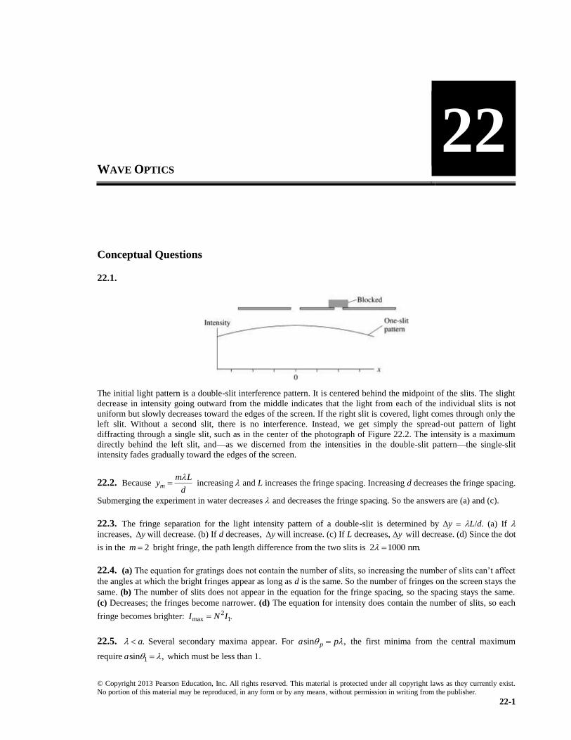
The initial light pattern is a double-slit interference pattern. It is centered behind the midpoint of the slits. The slight
decrease in intensity going outward from the middle indicates that the light from each of the individual slits is not
uniform but slowly decreases toward the edges of the screen. If the right slit is covered, light comes through only the
left slit. Without a second slit, there is no interference. Instead, we get simply the spread-out pattern of light
diffracting through a single slit, such as in the center of the photograph of Figure 22.2. The intensity is a maximum
directly behind the left slit, and—as we discerned from the intensities in the double-slit pattern—the single-slit
intensity fades gradually toward the edges of the screen.
22.2. Because m
m Ly
d
increasing and L increases the fringe spacing. Increasing d decreases the fringe spacing.
Submerging the experiment in water decreases and decreases the fringe spacing. So the answers are (a) and (c).
22.3. The fringe separation for the light intensity pattern of a double-slit is determined by y L/d. (a) If
increases, y will decrease. (b) If d decreases, y will increase. (c) If L decreases, y will decrease. (d) Since the dot
is in the 2m bright fringe, the path length difference from the two slits is 2 1000 nm
22.4. (a) The equation for gratings does not contain the number of slits, so increasing the number of slits can’t affect
the angles at which the bright fringes appear as long as d is the same. So the number of fringes on the screen stays the
same. (b) The number of slits does not appear in the equation for the fringe spacing, so the spacing stays the same.
(c) Decreases; the fringes become narrower. (d) The equation for intensity does contain the number of slits, so each
fringe becomes brighter: 2max 1I N I
22.5. .a Several secondary maxima appear. For sin ,pa p the first minima from the central maximum
require 1sin ,a which must be less than 1.
WAVE OPTICS
22
22-2 Chapter 22
© Copyright 2013 Pearson Education, Inc. All rights reserved. This material is protected under all copyright laws as they currently exist. No portion of this material may be reproduced, in any form or by any means, without permission in writing from the publisher.
22.6. (a) The width increases because 1
1 22.
D
(b) The width decreases because 1
1 22.
D
(c) Almost
uniformly gray with no minima.
22.7. When the experiment is immersed in water the frequency of the light stays the same. But the speed is slower,
so the wavelength is smaller. When the wavelength is smaller the fringes get closer together because L
yd
22.8. (a) Because the hole is so large we do not use the wave model of light. The ray model says we treat the light
as if it travels in straight lines, so increasing the hole diameter will increase the size of the spot on the screen. (b)
When the hole is smaller than 1 mm we need to consider diffraction effects; making the hole 20% larger will
decrease the diameter of the spot on the screen.
22.9. Moving a mirror by 200 nm increases or decreases the path length by 400 nm. Since one mirror is moved in
and the other out each increases the path length difference by 400 nm. The total is a path length difference of 800 nm,
so the spot will still be bright.
22.10. If the wavelength is changed to /2 there will still be crests everywhere there were crests before (plus new
crests halfway between, where there used to be troughs). If the interferometer was set up to display constructive
interference originally, then crests were arriving from each arm of the interferometer together at the detector. That
will still be true when the wavelength is halved. So the central spot remains bright.
Exercises and Problems
Section 22.2 The Interference of Light
22.1. Model: Two closely spaced slits produce a double-slit interference pattern.
Visualize: The interference pattern looks like the photograph of Figure 22.3(b). It is symmetrical with the 3m
fringes on both sides of and equally distant from the central maximum.
Solve: The bright fringes occur at angles m such that
sin 0, 1, 2, 3, md m m
9
3 36
3(600 10 m) 180sin 0 0225 0 023 rad 0 023 rad 1 3
rad(80 10 m)
22.2. Model: Two closely spaced slits produce a double-slit interference pattern.
Visualize: The interference pattern looks like the photograph of Figure 22.3(b).
Solve: The bright fringes are located at positions given by Equation 22.4, sin .md m For the m 3 bright orange
fringe, the interference condition is 93sin 3(600 10 m).d For the m 4 bright fringe the condition is 4sin 4d
Because the position of the fringes is the same, 9 93
3 4 4sin sin 4 3(600 10 m) (600 10 m) 450 nmd d
22.3. Model: Two closely spaced slits produce a double-slit interference pattern.
Visualize: The interference pattern looks like the photograph of Figure 22.3(b). It is symmetrical, with the 2m
fringes on both sides of and equally distant from the central maximum.
Solve: The two paths from the two slits to the 2m bright fringe differ by 2 1,r r r where
2 2(500 nm) 1000 nmr m
Thus, the position of the 2m bright fringe is 1000 nm farther away from the more distant slit than from the nearer slit.
Wave Optics 22-3
© Copyright 2013 Pearson Education, Inc. All rights reserved. This material is protected under all copyright laws as they currently exist. No portion of this material may be reproduced, in any form or by any means, without permission in writing from the publisher.
22.4. Model: Two closely spaced slits produce a double-slit interference pattern.
Visualize: The interference pattern looks like the photograph of Figure 22.3(b).
Solve: The formula for fringe spacing is
3 91 8 10 m (600 10 m) 3000L L L
yd d d
The wavelength is now changed to 400 nm, and / ,L d being a part of the experimental setup, stays the same.
Applying the above equation once again,
9(400 10 m)(3000) 1 2 mmL
yd
22.5. Visualize: The fringe spacing for a double slit pattern is L
yd
We are given L 2.0 m and 600 nm
We also see from the figure that 13
cmy
Solve: Solve the equation for d. 9
213
(600 10 m)(2 0 m)0 36 mm
10 m
Ld
y
Assess: 0.36 mm is a typical slit spacing.
22.6. Model: Two closely spaced slits produce a double-slit interference pattern.
Visualize: The interference pattern looks like the photograph of Figure 22.3(b).
Solve: The fringe spacing is 9 2
3
(589 10 m)(150 10 m)0 22 mm
4 0 10 m
L Ly d
d y
22.7. Model: Two closely spaced slits produce a double-slit interference pattern.
Visualize: The interference fringes are equally spaced on both sides of the central maximum. The interference
pattern looks like Figure 22.3(b).
Solve: In the small-angle approximation
1 ( 1)m m m md d d
Since 200 ,d we have
1 rad 0 286
200d
22.8. Model: Two closely spaced slits produce a double-slit interference pattern.
Visualize: The interference pattern looks like the photograph of Figure 22.3(b).
Solve: The dark fringes are located at positions given by Equation 22.9:
12
0, 1, 2, 3, m
Ly m m
d
2
31 15 1 2 2 3
4 (60 10 m)5 1 6 0 10 m 500 nm
0 20 10 m
L Ly y
d d
Section 22.3 The Diffraction Grating
22.9. Model: A diffraction grating produces an interference pattern.
Visualize: The interference pattern looks like the diagram in Figure 22.8.
Solve: The bright constructive-interference fringes are given by Equation 22.15:
sin 0, 1, 2, md m m
9
1 12
(1)(550 10 m)sin 0 0275 1 6
(4 0 10 m)/2000
Likewise, 2 2sin 0 055 and 3 2 .
22-4 Chapter 22
© Copyright 2013 Pearson Education, Inc. All rights reserved. This material is protected under all copyright laws as they currently exist. No portion of this material may be reproduced, in any form or by any means, without permission in writing from the publisher.
22.10. Model: A diffraction grating produces a series of constructive-interference fringes at values of m
determined by Equation 22.15.
Solve: We have
2sin 0, 1, 2, 3, sin20 0 1 and sin 2md m m d d
Dividing these two equations,
2 2sin 2sin20 0 0 6840 43 2
22.11. Model: A diffraction grating produces an interference pattern.
Visualize: The interference pattern looks like the diagram in Figure 22.8.
Solve: The bright constructive-interference fringes are given by Equation 22.15:
96(2)(600 10 m)
sin 1 89 10 msin sin(39 5 )
mm
md m d
The number of lines in per millimeter is 3 6(1 10 m)/(1 89 10 m) 530.
22.12. Model: A diffraction grating produces an interference pattern.
Visualize: The interference pattern looks like the diagram of Figure 22.8.
Solve: The bright interference fringes are given by
sin m 0, 1, 2, 3, md m
The slit spacing is 61 mm/500 2 00 10 md and 1.m For the red and blue light,
9 91 1
1 red 1 blue6 6
656 10 m 486 10 msin 19 15 sin 14 06
2 00 10 m 2 00 10 m
The distance between the fringes, then, is 1 red 1 bluey y y where
1 red
1 blue
(1 5 m)tan19 15 0 521 m
(1 5 m)tan14 06 0 376 m
y
y
So, 0 145 m 14 5 cmy
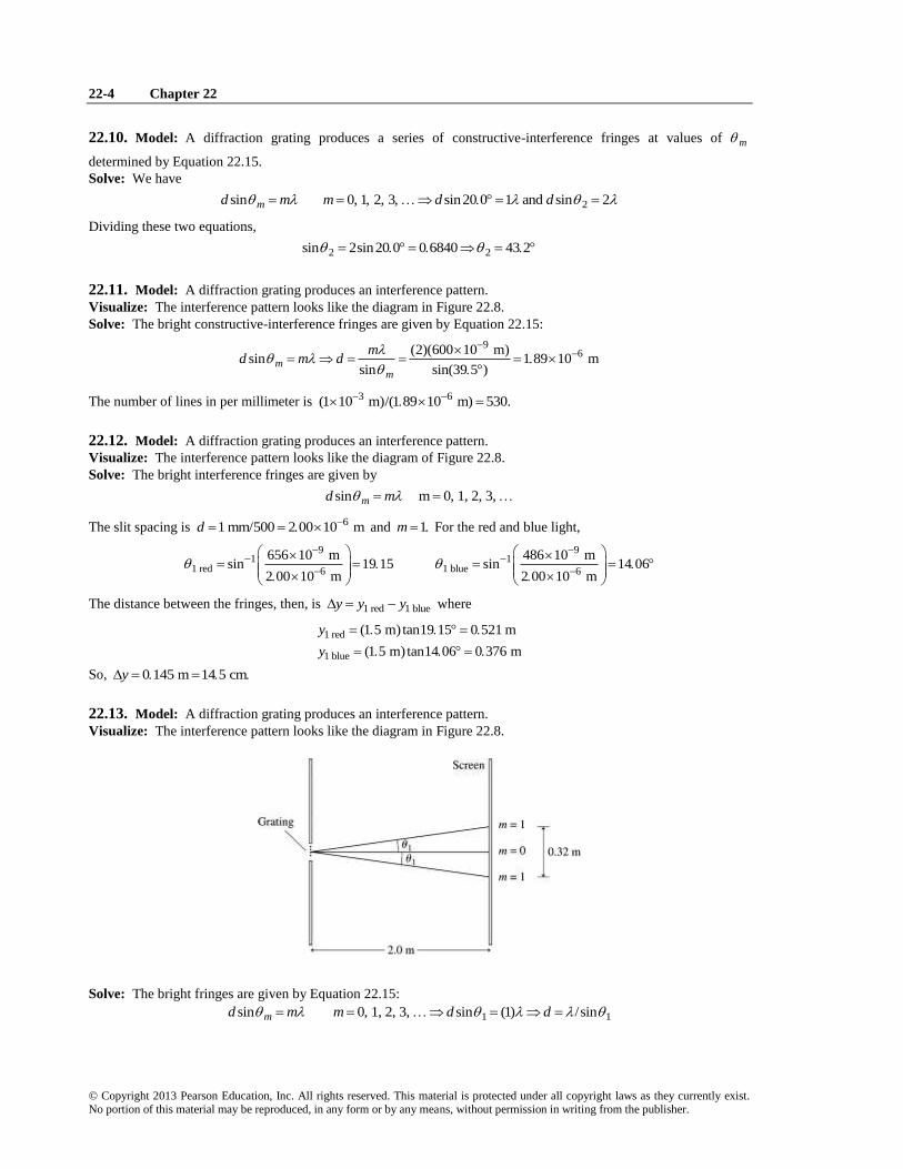
22.13. Model: A diffraction grating produces an interference pattern.
Visualize: The interference pattern looks like the diagram in Figure 22.8.
Solve: The bright fringes are given by Equation 22.15:
1 1sin 0, 1, 2, 3, sin (1) /sinmd m m d d
Wave Optics 22-5
© Copyright 2013 Pearson Education, Inc. All rights reserved. This material is protected under all copyright laws as they currently exist. No portion of this material may be reproduced, in any form or by any means, without permission in writing from the publisher.
The angle 1 can be obtained from geometry as follows:
11 1
(0 32 m)/2tan 0 080 tan (0.080) 4.57
2 0 m
Using 1sin sin4 57 0 07968,
9633 10 m7 9 m
0 07968d
22.14. Model: A diffraction grating produces a series of constructive-interference fringes at values of m that are
determined by Equation 22.15.
Solve: For the m 3 maximum of the red light and the m 5 maximum of the unknown wavelength, Equation 22.15
gives 9
3 5 unknownsin 3(660 10 m) sin 5d d
The 5m fringe and the 3m fringe have the same angular positions. This means 5 3. Dividing the two
equations, 9
unknown unknown5 3(660 10 m) 396 nm
Section 22.4 Single-Slit Diffraction
22.15. Model: A narrow single slit produces a single-slit diffraction pattern.
Visualize: The intensity pattern for single-slit diffraction will look like Figure 22.14.
Solve: The minima occur at positions
p
Ly p
a
94
2 1
2 1 (633 10 m)(1 5 m)So 2 0 10 m 0 20 mm
0 00475 m
L L L Ly y y a
a a a y
22.16. Model: A narrow slit produces a single-slit diffraction pattern.
Visualize: The intensity pattern for single-slit diffraction will look like Figure 22.14.
Solve: The width of the central maximum for a slit of width 200a is
2 2 (2 0 m)20 mm
200
Lw
a
22.17. Visualize: We are given 1 0 mL and 4000 .w
Solve: Solve 2 L
wa
for a.
2 2 (1 0 m) 1 0 m0 50 mm
4000 2000
La
w
Assess: This is a typical slit width.
22.18. Visualize: Use Equation 22.22: 2 L
wa
We are given 600 nm and L 2.0 m. We see from the figure
that 1 0 cmw
Solve: Solve the equation for a. 92 2(600 10 m)(2 0 m)
0 24 mm0 010 m
La
w
Assess: 0.24 mm is in the range of typical slit widths.
22-6 Chapter 22
© Copyright 2013 Pearson Education, Inc. All rights reserved. This material is protected under all copyright laws as they currently exist. No portion of this material may be reproduced, in any form or by any means, without permission in writing from the publisher.
22.19. Model: A narrow slit produces a single-slit diffraction pattern.
Visualize: The intensity pattern for single-slit diffraction will look like Figure 22.14.
Solve: The width of the central maximum for a slit of width 200a is 92 2(500 10 m)(2 0 m)
0 0040 m 4 0 mm0 0005 m
Lw
a
22.20. Model: The spacing between the two buildings is like a single slit and will cause the radio waves to be
diffracted.
Solve: Radio waves are electromagnetic waves that travel with the speed of light. The wavelength of the 800 MHz
waves is 8
6
3 10 m/s0 375 m
800 10 Hz
To investigate the diffraction of these waves through the spacing between the two buildings, we can use the general
condition for complete destructive interference: sin 1, 2, 3, pa p p where a is the spacing between the
buildings. Because the width of the central maximum is defined as the distance between the two 1p minima on
either side of the central maximum, we will use 1p and obtain the angular width 12 from
1 11 1
0 375 msin sin sin 1 43
15 ma
a
Thus, the angular width of the wave after it emerges from between the buildings is 2(1 43 ) 2 86 2 9
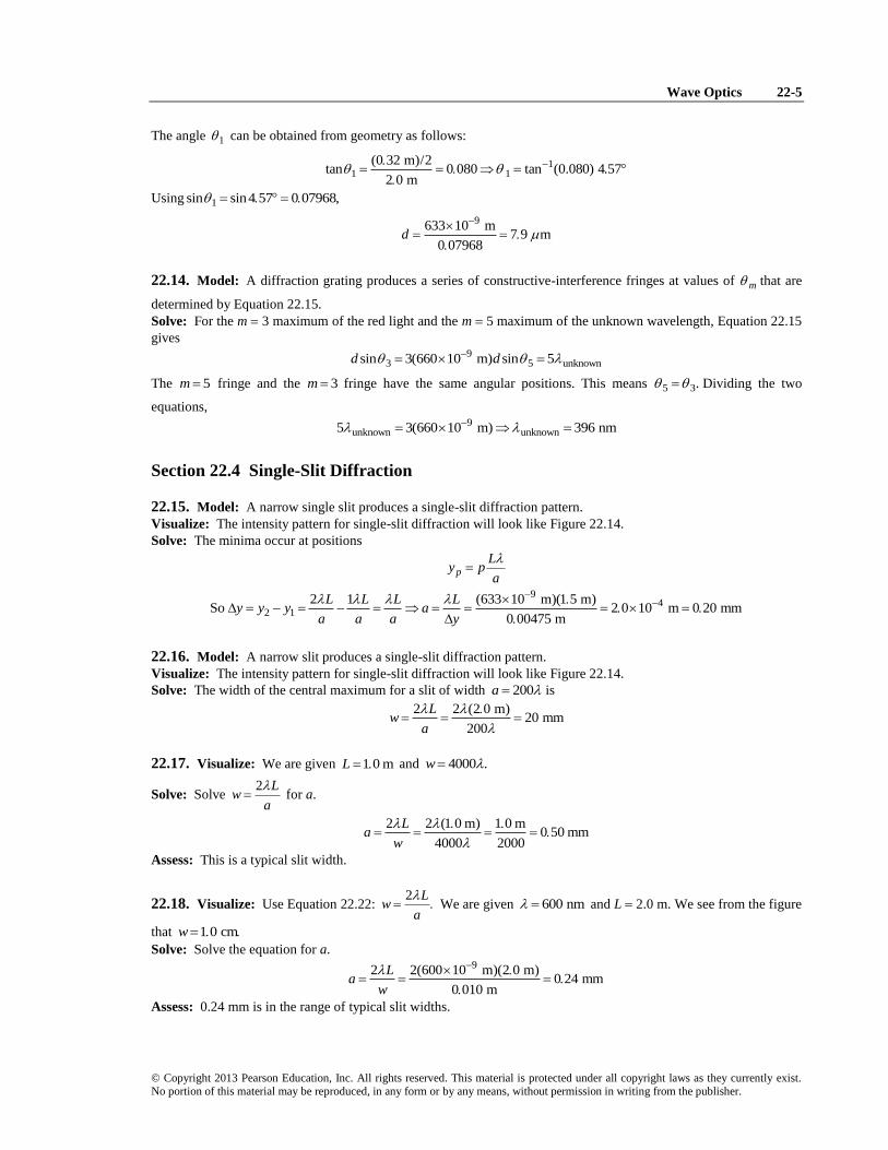
22.21. Model: The crack in the cave is like a single slit that causes the ultrasonic sound beam to diffract.
Visualize:
Solve: The wavelength of the ultrasound wave is
340 m/s0 0113 m
30 kHz
Using the condition for complete destructive interference with 1,p
11 1
0 0113 msin sin 2 165
0 30 ma
From the geometry of the diagram, the width of the sound beam is
1 12 2(100 m tan ) 200 m tan2 165 7 6 mw y
Assess: The small-angle approximation is almost always valid for the diffraction of light, but may not be valid for
the diffraction of sound waves, which have a much larger wavelength.
Section 22.5 Circular-Aperture Diffraction
22.22. Model: Light passing through a circular aperture leads to a diffraction pattern that has a circular central
maximum surrounded by a series of secondary bright fringes.
Wave Optics 22-7
© Copyright 2013 Pearson Education, Inc. All rights reserved. This material is protected under all copyright laws as they currently exist. No portion of this material may be reproduced, in any form or by any means, without permission in writing from the publisher.
Solve: The width of the central maximum for a circular aperture of diameter D is 9
3
2 44 (2 44)(500 10 m)(2 0 m)4.9 mm
0 50 10 m
Lw
D
22.23. Model: Light passing through a circular aperture leads to a diffraction pattern that has a circular central
maximum surrounded by a series of secondary bright fringes.
Visualize: The intensity pattern will look like Figure 22.15.
Solve: According to Equation 22.23, the angle that locates the first minimum in intensity is 6
1 3
1 22 (1 22)(2.5 10 m)0.01525 rad 0.874
0 20 10 mD
These should be rounded to 0.015 rad 0.87 .
22.24. Model: Light passing through a circular aperture leads to a diffraction pattern that has a circular central
maximum surrounded by a series of secondary bright fringes.
Visualize: The intensity pattern will look like Figure 22.15.
Solve: From Equation 22.24, 3 2
9
(0 12 10 m)(1 0 10 m)78 cm
2 44 2 44(633 10 m)
DwL
22.25. Model: Light passing through a circular aperture leads to a diffraction pattern that has a circular central
maximum surrounded by a series of secondary bright fringes.
Visualize: The intensity pattern will look like Figure 22.15.
Solve: From Equation 22.24, the diameter of the circular aperture is 9
2
2 44 2 44(633 10 m)(4 0 m)0 25 mm
2 5 10 m
LD
w
Section 22.6 Interferometers
22.26. Model: An interferometer produces a new maximum each time 2L increases by 12 causing the path-length
difference r to increase by .
Visualize: Please refer to the interferometer in Figure 22.20.
Solve: From Equation 22.33, the number of fringe shifts is 2
29
2 2(1 00 10 m)30,467
656 45 10 m
Lm
22.27. Model: An interferometer produces a new maximum each time 2L increases by 12 causing the path-length
difference r to increase by .
Visualize: Please refer to the interferometer in Figure 22.20.
Solve: From Equation 22.33, the wavelength is 6
722 2(100 10 m)4 0 10 m 400 nm
500
L
m
22.28. Model: An interferometer produces a new maximum each time 2L increases by 12 causing the path-length
difference r to increase by .
Visualize: Please refer to the interferometer in Figure 22.20.
Solve: From Equation 22.33, the distance the mirror moves is 9
2
(33,198)(602 446 10 m)0 0100000 m 1 00000 cm
2 2
mL
Assess: Because the wavelength is known to 6 significant figures and the fringes are counted exactly, we can
determine L to 6 significant figures.
22-8 Chapter 22
© Copyright 2013 Pearson Education, Inc. All rights reserved. This material is protected under all copyright laws as they currently exist. No portion of this material may be reproduced, in any form or by any means, without permission in writing from the publisher.
22.29. Model: An interferometer produces a new maximum each time 2L increases by 12 causing the path-length
difference r to increase by .
Visualize: Please refer to the interferometer in Figure 22.20.
Solve: For sodium light of the longer wavelength 1( ) and of the shorter wavelength 2( ),
1 2( 1)
2 2L m L m
We want the same path difference 2 12( )L L to correspond to one extra wavelength for the sodium light of shorter
wavelength 2( ). Thus, we combine the two equations to obtain:
1 2 21 2 2
1 2
589 0 nm( 1) ( ) 981 67 982
2 2 589 6 nm 589 0 nmm m m m
Thus, the distance by which 2M is to be moved is
1 589 6 nm982 0 2895 mm
2 2L m
22.30. Model: Two closely spaced slits produce a double-slit interference pattern with the intensity graph looking
like Figure 22.3(b). The intensity pattern due to a single slit diffraction looks like Figure 22.14. Both the spectra
consist of a central maximum flanked by a series of secondary maxima and dark fringes.
Solve: (a) The light intensity shown in Figure P22.30 corresponds to a double-slit aperture. This is because the
fringes are equally spaced and the decrease in intensity with increasing fringe order occurs slowly.
(b) From Figure P22.30, the fringe spacing is 21 0 cm 1 0 10 my Therefore,
9(6 00 10 m)(2 5 m)0 15 mm
0 010 m
L Ly d
d y
22.31. Model: Two closely spaced slits produce a double-slit interference pattern with the intensity graph looking
like Figure 22.3(b). The intensity pattern due to a single slit diffraction looks like Figure 22.14. Both the spectra
consist of a central maximum flanked by a series of secondary maxima and dark fringes.
Solve: (a) The light intensity shown in Figure P22.31 corresponds to a single slit aperture. This is because the
central maximum is twice the width and much brighter than the secondary maximum.
(b) From Figure P22.31, the separation between the central maximum and the first minimum is 2
1 1.0 cm 1.0 10 m.y Therefore, using the small-angle approximation, Equation 22.21 gives the condition for
the dark minimum: 9
21
(2 5 m)(600 10 m)0 15 mm
1 0 10 mp
pL Ly a
d y
22.32. Model: Two closely spaced slits produce a double-slit interference pattern.
Visualize: The interference pattern looks like the photograph of Figure 22.3(b).
Solve: In a span of 12 fringes, there are 11 gaps between them. The formula for the fringe spacing is
3 952 10 m (633 10 m)(3 0 m)d 0.40 mm
11
Ly
d d
Assess: This is a reasonable distance between the slits, ensuring 4/ 1 34 10 1.d L
22.33. Solve: According to Equation 22.7, the fringe spacing between the m fringe and the m 1 fringe is
/ .y L d y can be obtained from Figure P22.33. The separation between the 2m fringes is 2.0 cm, implying
that the separation between the two consecutive fringes is 14
(2.0 cm) 0.50 cm. Thus,
3 22
9
(0 20 10 m)(0 50 10 m)0 50 10 m 167 cm
600 10 m
L d yy L
d
Assess: A distance of 167 cm from the slits to the screen is reasonable.
Wave Optics 22-9
© Copyright 2013 Pearson Education, Inc. All rights reserved. This material is protected under all copyright laws as they currently exist. No portion of this material may be reproduced, in any form or by any means, without permission in writing from the publisher.
22.34. Solve: According to Equation 22.7, the fringe spacing between the m fringe and the m 1 fringe is
/ .y L d y can be obtained from Figure P22.33. Because the separation between the 2m fringes is 2.0 cm, two
consecutive fringes are 14
(2 0 cm) 0 50 cmy apart. Thus,
3 22 (0 20 10 m)(0 50 10 m)
0 50 10 m 500 nm2 0 m
L d yy
d L
22.35. Solve: The intensity of light of a double-slit interference pattern at a position y on the screen is
2double 14 cos
dI I y
L
where 1I is the intensity of the light from each slit alone. At the center of the screen, that is, at 0 m,y 11 double4
.I I
From Figure P22.33, doubleI at the central maximum is 212 mW/m . So, the intensity due to a single slit
is 21 3 mW/mI
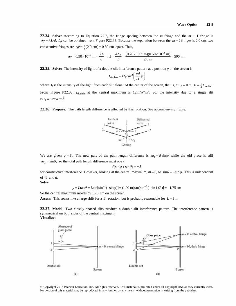
22.36. Prepare: The path length difference is affected by this rotation. See accompanying figure.
We are given 1 The new part of the path length difference is 1 sinr d while the old piece is still
2 sin ,r so the total path length difference must obey
(sin sin )d m
for constructive interference. However, looking at the central maximum, 0,m so sin sin This is independent
of and d.
Solve: 1 1tan tan[sin ( sin )] (1.00 m)tan[sin ( sin1.0 )] 1 75 cmy L L
So the central maximum moves by 1.75 cm on the screen
Assess: This seems like a large shift for a 1 rotation, but is probably reasonable for 1m.L
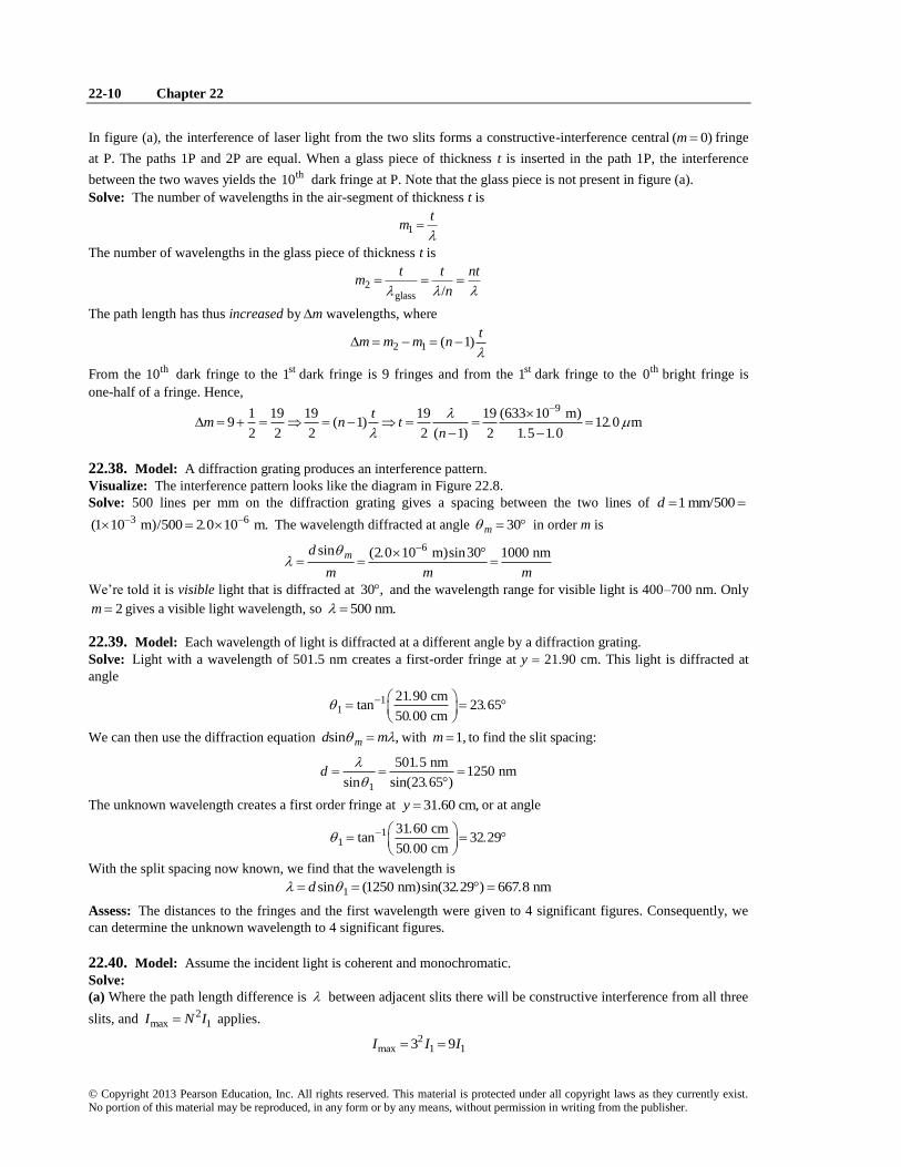
22.37. Model: Two closely spaced slits produce a double-slit interference pattern. The interference pattern is
symmetrical on both sides of the central maximum.
Visualize:
22-10 Chapter 22
© Copyright 2013 Pearson Education, Inc. All rights reserved. This material is protected under all copyright laws as they currently exist. No portion of this material may be reproduced, in any form or by any means, without permission in writing from the publisher.
In figure (a), the interference of laser light from the two slits forms a constructive-interference central ( 0)m fringe
at P. The paths 1P and 2P are equal. When a glass piece of thickness t is inserted in the path 1P, the interference
between the two waves yields the th10 dark fringe at P. Note that the glass piece is not present in figure (a).
Solve: The number of wavelengths in the air-segment of thickness t is
1
tm
The number of wavelengths in the glass piece of thickness t is
2glass /
t t ntm
n
The path length has thus increased by m wavelengths, where
2 1 ( 1)t
m m m n
From the th10 dark fringe to the st1 dark fringe is 9 fringes and from the st1 dark fringe to the th0 bright fringe is
one-half of a fringe. Hence, 91 19 19 19 19 (633 10 m)
9 ( 1) 12 0 m2 2 2 2 ( 1) 2 1 5 1 0
tm n t
n
22.38. Model: A diffraction grating produces an interference pattern.
Visualize: The interference pattern looks like the diagram in Figure 22.8.
Solve: 500 lines per mm on the diffraction grating gives a spacing between the two lines of 1 mm/500d 3 6(1 10 m)/500 2 0 10 m. The wavelength diffracted at angle 30m in order m is
6sin (2 0 10 m)sin30 1000 nmmd
m m m
We’re told it is visible light that is diffracted at 30 , and the wavelength range for visible light is 400–700 nm. Only
2m gives a visible light wavelength, so 500 nm.
22.39. Model: Each wavelength of light is diffracted at a different angle by a diffraction grating.
Solve: Light with a wavelength of 501.5 nm creates a first-order fringe at y 21.90 cm. This light is diffracted at
angle
11
21 90 cmtan 23 65
50 00 cm
We can then use the diffraction equation sin ,md m with 1,m to find the slit spacing:
1
501 5 nm1250 nm
sin sin(23 65 )d
The unknown wavelength creates a first order fringe at 31.60 cm,y or at angle
11
31 60 cmtan 32 29
50 00 cm
With the split spacing now known, we find that the wavelength is
1sin (1250 nm)sin(32 29 ) 667 8 nmd
Assess: The distances to the fringes and the first wavelength were given to 4 significant figures. Consequently, we
can determine the unknown wavelength to 4 significant figures.
22.40. Model: Assume the incident light is coherent and monochromatic.
Solve:
(a) Where the path length difference is between adjacent slits there will be constructive interference from all three
slits, and 2max 1I N I applies.
2max 1 13 9I I I
Wave Optics 22-11
© Copyright 2013 Pearson Education, Inc. All rights reserved. This material is protected under all copyright laws as they currently exist. No portion of this material may be reproduced, in any form or by any means, without permission in writing from the publisher.
(b) For the case where the path length difference is /2 adjacent slits will produce destructive interference, so the
third slit will just give a total intensity of 1.I
22.41. Model: We will assume that the listeners did not hear any other loud spots between the center and 1.4 m on
each side, 1.m We’ll use the diffraction grating equations. First solve Equation 22.16 for 1 and insert it into
Equation 22.15.
We need the wavelength of the sound waves, and we’ll use the fundamental relationship for periodic waves to get it.
340 m/s3 4 cm 0 034 m
10000 Hz
v
f
We are also given 10 mL and 1 1 4 my
Solve:
1 111
1 4 mtan tan 0 14 rad
10 m
y
L
(This may be small enough to use the small-angle approximation, but we are almost finished with the problem
without it, so maybe we can save the approximation and try it in the assess step.)
1
(1) 0 034 m0 25 m 25 cm
sin sin(0 14 rad)d
Assess: These numbers seem reasonable given the size (wavelength) of sound waves.
With the small-angle approximation, sin tan ,
1(0 034 m)24 cm
/ 1 4 m/10 mm
md
y L
This is almost the same, but rounded down to two significant figures rather than up. The 1 we computed seemed
almost small enough to use the approximation, and it would probably be OK for many applications when the angle is
this small.
22.42. Model: A diffraction grating produces an interference pattern.
Visualize: The interference pattern looks like the diagram of Figure 22.8.
Solve: (a) A grating diffracts light at angles sin / .m m d The distance between adjacent slits is 1 mm/600d
61 667 10 m 1667 nm The angle of the 1m fringe is
11
500 nmsin 17 46
1667 nm
The distance from the central maximum to the 1m bright fringe on a screen at distance L is o
1 1tan (2 m)tan17 46 0 629 my L
(Note that the small angle approximation is not valid for the maxima of diffraction gratings, which almost always
have angles 10 . ) There are two 1m bright fringes, one on either side of the central maximum. The distance
between them is 12 1 258 m 1 3 my y
(b) The maximum number of fringes is determined by the maximum value of m for which sin m does not exceed 1
because there are no physical angles for which sin 1. In this case,
(500 nm)sin
1667 nmm
m m
d
We can see by inspection that m 1, m 2, and m 3 are acceptable, but m 4 would require a physically
impossible 4sin 1 Thus, there are three bright fringes on either side of the central maximum plus the central
maximum itself for a total of seven bright fringes.
22.43. Model: Assume the screen is centered behind the slit. We actually want to solve for m, but given the other
data, it is unlikely that we will get an integer from the equations for the edge of the screen, so we will have to
truncate our answer to get the largest order fringe on the screen.
22-12 Chapter 22
© Copyright 2013 Pearson Education, Inc. All rights reserved. This material is protected under all copyright laws as they currently exist. No portion of this material may be reproduced, in any form or by any means, without permission in writing from the publisher.
Visualize: Refer to Figure 22.7. Use Equation 22.15: sin ,md m and Equation 22.16: tanm my L We are
given 510 nm, 2 0 m,L and 1500
mmd As mentioned above, we are not guaranteed that a bright fringe will
occur exactly at the edge of the screen, but we will kind of assume that one does and set 1 0 m;my if we do not get
an integer for m then the fringe was not quite at the edge of the screen and we will truncate our answer to get an
integer m.
Solve: Solve Equation 22.16 for m and insert it in Equation 22.15.
1tan mm
y
L
Solve Equation 22.15 for m
11 1500
mm 1 0 msin sin tan sin tan 1 8
510 nm 2 0 m
mm
d d ym
L
Indeed, we did not get an integer, so truncate 1.8 to get 1m This means we will see three fringes, one for 0,m
and one on each side for 1m
Assess: Our answer fits with the statement in the text: “Practical gratings, with very small values for ,d display only
a few orders.”
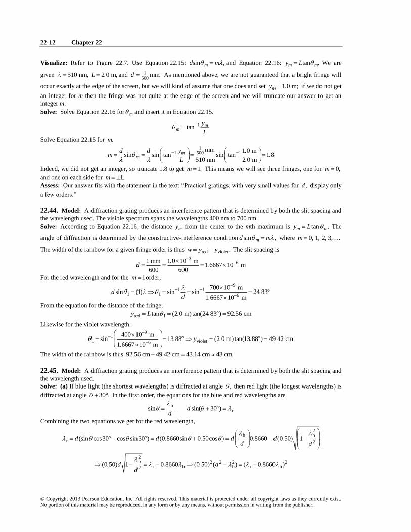
22.44. Model: A diffraction grating produces an interference pattern that is determined by both the slit spacing and
the wavelength used. The visible spectrum spans the wavelengths 400 nm to 700 nm.
Solve: According to Equation 22.16, the distance my from the center to the mth maximum is tan .m my L The
angle of diffraction is determined by the constructive-interference condition sin ,md m where 0, 1, 2, 3, m
The width of the rainbow for a given fringe order is thus red violet.w y y The slit spacing is
361 mm 1 0 10 m
1 6667 10 m600 600
d
For the red wavelength and for the 1m order, 9
1 11 1 6
700 10 msin (1) sin sin 24 83
1 6667 10 md
d
From the equation for the distance of the fringe,
red 1tan (2 0 m)tan(24 83 ) 92 56 cmy L
Likewise for the violet wavelength,
91
1 violet6
400 10 msin 13 88 (2 0 m) tan(13 88 ) 49 42 cm
1 6667 10 my
The width of the rainbow is thus 92.56 cm 49.42 cm 43.14 cm 43 cm.
22.45. Model: A diffraction grating produces an interference pattern that is determined by both the slit spacing and
the wavelength used.
Solve: (a) If blue light (the shortest wavelengths) is diffracted at angle , then red light (the longest wavelengths) is
diffracted at angle 30°. In the first order, the equations for the blue and red wavelengths are
brsin sin( 30 )d
d
Combining the two equations we get for the red wavelength,
2b b
r 2(sin cos30 cos sin30 ) (0 8660sin 0 50cos ) 0 8660 (0 50) 1d d d d
d d
2b 2 2 2 2
r b b r b2(0 50) 1 0 8660 (0 50) ( ) ( 0 8660 )d d
d
Wave Optics 22-13
© Copyright 2013 Pearson Education, Inc. All rights reserved. This material is protected under all copyright laws as they currently exist. No portion of this material may be reproduced, in any form or by any means, without permission in writing from the publisher.
2r b 2
b
0 8660
0 50d
Using 9b 400 10 m and 9
r 700 10 m, we get 78 125 10 md This value of d corresponds to
3
7
1 mm 1 0 10 m1230 lines/mm
8 125 10 md
(b) Using the value of d from part (a) and 9589 10 m, we can calculate the angle of diffraction as follows:
7 91 1 1sin (1) (8 125 10 m)sin 589 10 m 46 5d
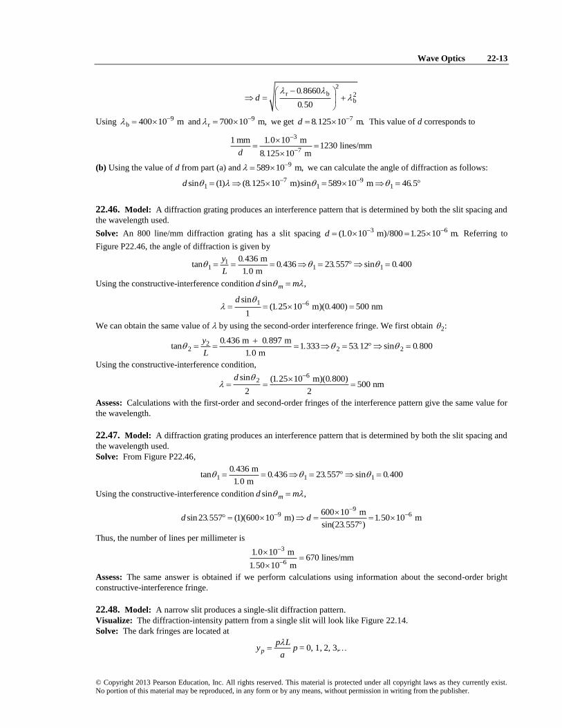
22.46. Model: A diffraction grating produces an interference pattern that is determined by both the slit spacing and
the wavelength used.
Solve: An 800 line/mm diffraction grating has a slit spacing 3 6(1 0 10 m)/800 1 25 10 md Referring to
Figure P22.46, the angle of diffraction is given by
11 1 1
0 436 mtan 0 436 23 557 sin 0 400
1 0 m
y
L
Using the constructive-interference condition sin ,md m
1 6sin
(1 25 10 m)(0 400) 500 nm1
d
We can obtain the same value of by using the second-order interference fringe. We first obtain 2:
22 2 2
0 436 m 0 897 mtan 1 333 53 12 sin 0 800
1 0 m
y
L
Using the constructive-interference condition,
62sin (1 25 10 m)(0 800)
500 nm2 2
d
Assess: Calculations with the first-order and second-order fringes of the interference pattern give the same value for
the wavelength.
22.47. Model: A diffraction grating produces an interference pattern that is determined by both the slit spacing and
the wavelength used.
Solve: From Figure P22.46,
1 1 1
0 436 mtan 0 436 23 557 sin 0 400
1 0 m
Using the constructive-interference condition sin ,md m
99 6600 10 m
sin 23 557 (1)(600 10 m) 1 50 10 msin(23 557 )
d d
Thus, the number of lines per millimeter is
3
6
1 0 10 m670 lines/mm
1 50 10 m
Assess: The same answer is obtained if we perform calculations using information about the second-order bright
constructive-interference fringe.
22.48. Model: A narrow slit produces a single-slit diffraction pattern.
Visualize: The diffraction-intensity pattern from a single slit will look like Figure 22.14.
Solve: The dark fringes are located at
0, 1, 2, 3,p
p Ly p =
a
22-14 Chapter 22
© Copyright 2013 Pearson Education, Inc. All rights reserved. This material is protected under all copyright laws as they currently exist. No portion of this material may be reproduced, in any form or by any means, without permission in writing from the publisher.
The locations of the first and third dark fringes are
1 3
3L Ly y
a a
Subtracting the two equations,
9
3 1 33 1
2 2 2(589 10 m)(0 75 m)( ) 0.12 mm
7 5 10 m
L Ly y a
a y y
22.49. Visualize: The relationship between the diffraction grating spacing d, the angle at which a particular order
of constructive interference occurs ,m the wavelength of the light, and the order of the constructive interference m
is sin .md m Also note 1/N d
Solve: The first order diffraction angle for green light is
1 1 7 6 11 sin ( / ) sin (5 5 10 m/2 0 10 m) sin (0 275) 0 278 rad 16d
Assess: This is a reasonable angle for a first order maximum.
22.50. Model: The peacock feather is acting as a reflection grating, so we may use Equation 22.15: sin ,md m
with 1m (we are told it is first-order diffraction), 470 nm, and 1 15 0 262 rad
Solve: Solve Equation 22.15 for d
9(1)(470 10 m)1 8 m
sin sin(0.262 rad)m
md
Assess: The answer is small, but plausible for the bands on the barbules.
22.51. Model: Assume the incident light is coherent and monochromatic.
Visualize: The distances given in the table are 12y since the measurement is between the two first order fringes.
Also note that 1m in this problem.
Solve: The equation for diffraction gratings is sin md m where d is the distance (in mm) between slits; we seek
1 ,d
the number of lines per mm.
1
1sin
d
From tanm my L and distance1 2
y , where “distance” is the distance between first order fringes as given in the
table, we arrive at
1 distance 1sin tan
2L d
This leads us to believe that a graph of 1 distancesin tan
2L
vs. will produce a straight line whose slope is 1
d and
whose intercept is zero.
Wave Optics 22-15
© Copyright 2013 Pearson Education, Inc. All rights reserved. This material is protected under all copyright laws as they currently exist. No portion of this material may be reproduced, in any form or by any means, without permission in writing from the publisher.
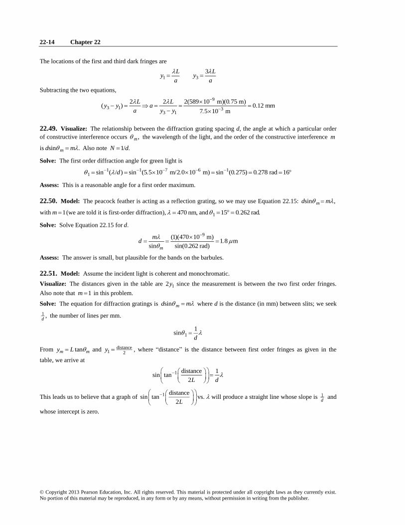
We see from the spreadsheet that the linear fit is excellent and that the slope is 1799.84 mm and the intercept is very
small. Because the number of lines per mm is always reported as an integer we round this answer to 800 lines/mm.
Assess: This number of lines per mm is a typical number for a decent grating.
22.52. Model: Small angle approximations would not apply here.
Visualize: We see from the figure that if 1y L then 1 45 .
Solve: From sin md m we get
1sind
but 1 45 , and 2
sin45 .2
2
2d
Assess: This large diffraction angle corresponds to a wavelength that is about the same size as the slit spacing.
22-16 Chapter 22
© Copyright 2013 Pearson Education, Inc. All rights reserved. This material is protected under all copyright laws as they currently exist. No portion of this material may be reproduced, in any form or by any means, without permission in writing from the publisher.
22.53. Model: A narrow slit produces a single-slit diffraction pattern.
Visualize: The diffraction-intensity pattern from a single slit will look like Figure 22.14.
Solve: These are not small angles, so we can’t use equations based on the small-angle approximation. As given by
Equation 22.19, the dark fringes in the pattern are located at sin ,pa p where 1, 2, 3, p For the first
minimum of the pattern, 1.p Thus,
1
1
sin sinp
a p
For the three given angles the slit width to wavelength ratios are
(a): 30
12,
sin30
a
(b):
60
11 15,
sin60
a
(c):
90
11
sin90
a
Assess: It is clear that the smaller the a/ ratio, the wider the diffraction pattern. This is a conclusion that is contrary
to what one might expect.
22.54. Model: A narrow slit produces a single-slit diffraction pattern.
Visualize: The diffraction-intensity pattern from a single slit will look like Figure 22.14.
Solve: As given by Equation 22.19, the dark fringes in the pattern are located at sin ,pa p where 1, 2, 3, p
For the diffraction pattern to have no minima, the first minimum must be located at least at 1 90 . From the
constructive-interference condition sin ,pa p we have
633 nmsin sin90p
pa a
22.55. Model: A narrow slit produces a single-slit diffraction pattern.
Visualize: The dark fringes in this diffraction pattern are given by Equation 22.21:
1, 2, 3,p
p Ly p
a
We note that the first minimum in the figure is 0.50 cm away from the central maximum. We are given a 0.02 nm
and 1 5 mL
Solve: Solve the above equation for 2 3(0 50 10 m)(0 20 10 m)
670 nm(1)(1 5 m)
py a
pL
Assess: 670 nm is in the visible range.
22.56. Model: A narrow slit produces a single-slit diffraction pattern.
Solve: The dark fringes in this diffraction pattern are given by Equation 22.21:
1, 2, 3,p
p Ly p
a
We note from Figure P22.55 that the first minimum is 0.50 cm away from the central maximum. Thus, 3 2
9
(0 15 10 m)(0 50 10 m)1.3 nm
(1)(600 10 m)
payL
p
Assess: This is a typical slit to screen separation.
22.57. Model: Light passing through a circular aperture leads to a diffraction pattern that has a circular central
maximum surrounded by a series of secondary bright fringes.
Solve: Within the small angle approximation, which is almost always valid for the diffraction of light, the width of
the central maximum is
12 2 44L
w yD
Wave Optics 22-17
© Copyright 2013 Pearson Education, Inc. All rights reserved. This material is protected under all copyright laws as they currently exist. No portion of this material may be reproduced, in any form or by any means, without permission in writing from the publisher.
From Figure P22.55, 1.0 cm,w so
9
2
2 44 2.44(500 10 m)(1.0 m)0.12 mm
(1.0 10 m)
LD
w
Assess: This is a typical size for an aperture to show diffraction.
22.58. Model: Light passing through a circular aperture leads to a diffraction pattern that has a circular central
maximum surrounded by a series of secondary bright fringes.
Solve: Within the small-angle approximation, the width of the central maximum is
2 44L
wD
Because ,w D we have
92 44 2 44 (2 44)(633 10 m)(0 50 m) 0 88 mmL
D D L DD
22.59. Model: Light passing through a circular aperture leads to a diffraction pattern that has a circular central
maximum surrounded by a series of secondary bright fringes.
Solve: (a) Because the visible spectrum spans wavelengths from 400 nm to 700 nm, we take the average wavelength
of sunlight to be 550 nm.
(b) Within the small-angle approximation, the width of the central maximum is 9
2 4(550 10 m)(3 m)2 44 (1 10 m) (2 44) 4 03 10 m 0 40 mm
Lw D
D D
22.60. Model: The antenna is a circular aperture through which the microwaves diffract.
Solve: (a) Within the small-angle approximation, the width of the central maximum of the diffraction pattern is
2.44 / .w L D The wavelength of the radiation is 8 3
9
3 10 m/s 2 44(0 025 m)(30 10 m)0 025 m 920 m
2 0 m12 10 Hz
cw
f
That is, the diameter of the beam has increased from 2.0 m to 915 m, a factor of 458.
(b) The average microwave intensity is 3
2
212
100 10 W0 15 W m
area (915 m)
PI /
22.61. Model: The laser light is diffracted by the circular opening of the laser from which the beam emerges.
Solve: The diameter of the laser beam is the width of the central maximum. We have 9 82 44 2 44 2 44(532 10 m)(3 84 10 m)
0 50 m1000 m
L Lw D
D w
In other words, the laser beam must emerge from a laser of diameter 50 cm.
22.62. Model: Two closely spaced slits produce a double-slit interference pattern.
22-18 Chapter 22
© Copyright 2013 Pearson Education, Inc. All rights reserved. This material is protected under all copyright laws as they currently exist. No portion of this material may be reproduced, in any form or by any means, without permission in writing from the publisher.
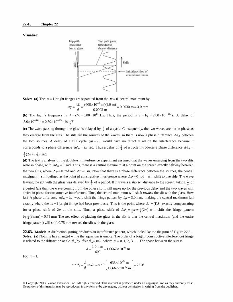
Visualize:
Solve: (a) The 1m bright fringes are separated from the 0m central maximum by 9(600 10 m)(1 0 m)
0 0030 m 3 0 mm0 0002 m
Ly
d
(b) The light’s frequency is 14/ 5.00 10 Hz.f c Thus, the period is 151/ 2.00 10 s.T f A delay of
16 15 14
5.0 10 s 0.50 10 s is .T
(c) The wave passing through the glass is delayed by 14
of a cycle. Consequently, the two waves are not in phase as
they emerge from the slits. The slits are the sources of the waves, so there is now a phase difference 0 between
the two sources. A delay of a full cycle ( )t T would have no effect at all on the interference because it
corresponds to a phase difference 0 2 rad Thus a delay of 14
of a cycle introduces a phase difference 0
1 14 2
(2 ) rad
(d) The text’s analysis of the double-slit interference experiment assumed that the waves emerging from the two slits
were in phase, with 0 0 rad. Thus, there is a central maximum at a point on the screen exactly halfway between
the two slits, where 0 rad and 0 m.r Now that there is a phase difference between the sources, the central
maximum—still defined as the point of constructive interference where 0 rad—will shift to one side. The wave
leaving the slit with the glass was delayed by 14
of a period. If it travels a shorter distance to the screen, taking 14
of
a period less than the wave coming from the other slit, it will make up for the previous delay and the two waves will
arrive in phase for constructive interference. Thus, the central maximum will shift toward the slit with the glass. How
far? A phase difference 0 2 would shift the fringe pattern by 3.0 mm,y making the central maximum fall
exactly where the 1m bright fringe had been previously. This is the point where (1) ,r exactly compensating
for a phase shift of 2π at the slits. Thus, a phase shift of 1 10 2 4
(2 ) will shift the fringe pattern
by 14
(3 mm) 0.75 mm. The net effect of placing the glass in the slit is that the central maximum (and the entire
fringe pattern) will shift 0.75 mm toward the slit with the glass.
22.63. Model: A diffraction grating produces an interference pattern, which looks like the diagram of Figure 22.8.
Solve: (a) Nothing has changed while the aquarium is empty. The order of a bright (constructive interference) fringe
is related to the diffraction angle m by sin ,md m where 0, 1, 2, 3, m The space between the slits is
61 0 mm1 6667 10 m
600d
For 1,m
91
1 1 6
633 10 msin sin 22 3
1 6667 10 md
Wave Optics 22-19
© Copyright 2013 Pearson Education, Inc. All rights reserved. This material is protected under all copyright laws as they currently exist. No portion of this material may be reproduced, in any form or by any means, without permission in writing from the publisher.
(b) The path-difference between the waves that leads to constructive interference is an integral multiple of the
wavelength in the medium in which the waves are traveling, that is, water. Thus, 7
71 16
water
633 nm 633 nm 4 759 10 m4 759 10 m sin 0 2855 16 6
1 33 1 6667 10 mn d
22.64. Model: An interferometer produces a new maximum each time 2L increases by 12 causing the path-
length difference r to increase by .
Visualize: Please refer to the interferometer in Figure 22.20.
Solve: The path-length difference between the two waves is 2 12 2 .r L L The condition for constructive
interference is ,r m hence constructive interference occurs when
1 12 1 2 1 22 2
2( ) 1200 600L L m L L m
where 632.8 nm is the wavelength of the helium-neon laser. When the mirror 2M is moved back and a hydrogen
discharge lamp is used, 1200 fringes shift again. Thus,
12 1 2
1200 600L L
where 656 5 nm Subtracting the two equations,
9 92 1 2 1( ) 600( ) 600(632 8 10 m 656 5 10 m)L L L L
62 2 14 2 10 mL L
That is, 2M is now 14.2 m closer to the beam splitter.
22.65. Model: The gas increases the number of wavelengths in one arm of the interferometer. Each additional
wavelength causes one bright-dark-bright fringe shift.
Solve: From the equation in Challenge Example 22.9, the number of fringe shifts is 2
2 1 9vac
2 (2)(2 00 10 m)( 1) (1 00028 1) 19
600 10 m
dm m m n
22.66. Model: The piece of glass increases the number of wavelengths in one arm of the interferometer. Each
additional wavelength causes one bright-dark-bright fringe shift.
Solve: We can rearrange the equation in Challenge Example 22.9 to find that the index of refraction of glass is 9
vac
3
(500 10 nm)(200)1 1 1.50
2 2(0 10 10 m)
mn
d
22.67. Model: The arms of the interferometer are of equal length, so without the crystal the output would be bright.
Visualize: We need to consider how many more wavelengths fit in the electro-optic crystal than would have
occupied that space (6.70 m) without the crystal; if it is an integer then the interferometer will produce a bright
output; if it is a half-integer then the interferometer will produce a dark output. But the wavelength we need to
consider is the wavelength inside the crystal, not the wavelength in air.
nn
We are told the initial n with no applied voltage is 1.522, and the wavelength in air is 1 000 m
Solve: The number of wavelengths that would have been in that space without the crystal is
6 70 m6 70
1 000 m
(a) With the crystal in place (and 1.522)n the number of wavelengths in the crystal is
6.70 m10.20
1.000 m/1.522
10.20 6.70 3.50
22-20 Chapter 22
© Copyright 2013 Pearson Education, Inc. All rights reserved. This material is protected under all copyright laws as they currently exist. No portion of this material may be reproduced, in any form or by any means, without permission in writing from the publisher.
which shows there are a half-integer number more wavelengths with the crystal in place than if it weren’t there.
Consequently the output is dark with the crystal in place but no applied voltage.
(b) Since the output was dark in the previous part, we want it to be bright in the new case with the voltage on. That
means we want to have just one-half more extra wavelengths in the crystal (than if it weren’t there) than we did in the
previous part. That is, we want 4.00 extra wavelengths in the crystal instead of 3.5, so we want 6.70 4.00 10.70
wavelengths in the crystal.
6 70 m 10 70(1 000 m)10 70 1 597
1 000 m/ 6 70 mn
n
Assess: It seems reasonable to be able to change the index of refraction of a crystal from 1.522 to 1.597 by applying
a voltage.
22.68. Model: A diffraction grating produces an interference pattern like the one shown in Figure 22.8. We also
assume that the small-angle approximation is valid for this grating.
Solve: (a) The general condition for constructive-interference fringes is
sin 0, 1, 2, 3, md m m
When this happens, we say that the light is diffracted at an angle .m Since it is usually easier to measure distances
rather than angles, we will consider the distance my from the center to the mth maximum. This distance is
tan .m my L In the small-angle approximation, sin tan ,m m so we can write the condition for constructive
interference as
mm
y m Ld m y
L d
The fringe separation is
1m m
Ly y y
d
(b) Now the laser light falls on a film that has a series of “slits” (i.e., bright and dark stripes), with spacing
Ld
d
Applying once again the condition for constructive interference:
sin/
mm m
y m L m Ld m d m y md
L d L d
The fringe separation is 1 .m my y y d
That is, using the film as a diffraction grating produces a diffraction pattern whose fringe spacing is d, the spacing of
the original slits.
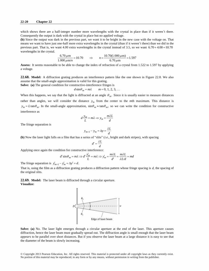
22.69. Model: The laser beam is diffracted through a circular aperture.
Visualize:
Solve: (a) No. The laser light emerges through a circular aperture at the end of the laser. This aperture causes
diffraction, hence the laser beam must gradually spread out. The diffraction angle is small enough that the laser beam
appears to be parallel over short distances. But if you observe the laser beam at a large distance it is easy to see that
the diameter of the beam is slowly increasing.
Wave Optics 22-21
© Copyright 2013 Pearson Education, Inc. All rights reserved. This material is protected under all copyright laws as they currently exist. No portion of this material may be reproduced, in any form or by any means, without permission in writing from the publisher.
(b) The position of the first minimum in the diffraction pattern is more or less the “edge” of the laser beam. For
diffraction through a circular aperture, the first minimum is at an angle 9
41
1 22 1 22(633 10 m)7 72 10 rad 0 044
0 0010 mD
(c) The diameter of the laser beam is the width of the diffraction pattern: 92 44 2 44(633 10 m)(3 0 m)
4 6 mm0 0010 m
Lw
D
(d) At 1 km 1000 m,L the diameter is
92 44 2 44(633 10 m)(1000 m)1 5 m
0 0010 m
Lw
D
22.70. Visualize: To find the location y where the intensity is 1I use Equation 22.14: 2double 14 cos .
dI I y
L
Then divide by the distance to the first minimum 0
1
2
Ly
d
to get the fraction desired.
Solve: First set double 1.I I
2double 14 cos
dI I y
L
21 14 cos
dI I y
L
21cos
4
dy
L
1cos
2
dy
L
1 1cos
2
Ly
d
Now set up the ratio that will give the desired fraction.
1
1
0
1cos
2 1 2 22cos
1 2 3 3
2
L
y d
Ly
d
Assess: The fraction must be less than 1, and 23
seems reasonable.
22.71. Model: A diffraction grating produces a series of constructive-interference fringes at values of m that are
determined by Equation 22.15.
Solve: (a) The condition for bright fringes is sin .d m If changes by a very small amount , such that
changes by , then we can approximate / as the derivative /dd
2 22 2sin cos 1 sin 1
d d d d d m d
m d m m m d m
22d
m
(b) We can now obtain the first-order and second-order angular separations for the wavelengths 589.0 nm and
589.6 nm. The slit spacing is 3
61 0 10 m1 6667 10 m
600d
22-22 Chapter 22
© Copyright 2013 Pearson Education, Inc. All rights reserved. This material is protected under all copyright laws as they currently exist. No portion of this material may be reproduced, in any form or by any means, without permission in writing from the publisher.
The first-order ( 1)m angular separation is
9 9
612 2 12 2
4
0 6 10 m 0 6 10 m
1 5589 10 m2 7778 10 m 0 3476 10 m
3 85 10 rad 0 022
The second order ( 2)m angular separation is
93
12 2 12 2
0 6 10 m1 02 10 rad 0 058
0 6945 10 m 0 3476 10 m
22.72. Model: The intensity in a double-slit interference pattern is determined by diffraction effects from the slits.
Solve: (a) For the two wavelengths and passing simultaneously through the grating, their first-order peaks
are at
1 1
( )L Ly y
d d
Subtracting the two equations gives an expression for the separation of the peaks:
1 1
Ly y y
d
(b) For a double-slit, the intensity pattern is
2double 14 cos
dI I y
L
The intensity oscillates between zero and 14 ,I so the maximum intensity is 14 .I The width is measured at the point
where the intensity is half of its maximum value. For the intensity to be 1max 12
2I I for the 1m peak:
2 21 1 half half half half
12 4 cos cos
2 4 4
d d d LI I y y y y
L L L d
The width of the fringe is twice half .y This means
half22
Lw y
d
But the location of the 1m peak is 1 / ,y L d so we get 112.w y
(c) We can extend the result obtained in (b) for two slits to 1/w y N The condition for barely resolving two
diffraction fringes or peaks is min.w y From part (a) we have an expression for the separation of the first-order
peaks and from part (b) we have an expression for the width. Thus, combining these two pieces of information,
min1 1min min
Ly y d L dy
N d LN d NL N
(d) Using the result of part (c),
9
9min
656 27 10 m3646 lines
0 18 10 mN
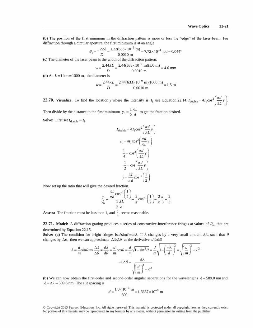
22.73. Model: A diffraction grating produces an interference pattern like the one shown in Figure 22.8, when the
incident light is normal to the grating. The equation for constructive interference will change when the light is
incident at a nonzero angle.
Wave Optics 22-23
© Copyright 2013 Pearson Education, Inc. All rights reserved. This material is protected under all copyright laws as they currently exist. No portion of this material may be reproduced, in any form or by any means, without permission in writing from the publisher.
Solve: (a) The path difference between waves 1 and 2 on the incident side is 1 sinr d The path difference between
the waves 1 and 2 on the diffracted side, however, is 2 sinr d The total path difference between waves 1 and 2 is
thus 1 2 (sin sin ).r r d Because the path difference for constructive interference must be equal to m,
(sin sin ) 0, 1, 2, d m m
(b) For 30 the angles of diffraction are
9
1 13
(1)(500 10 m)sin sin30 0 20 11 5
(1 0 10 m)/600
9
1 13
( 1)(500 10 m)sin sin30 0 80 53 1
(1 0 10 m)/600
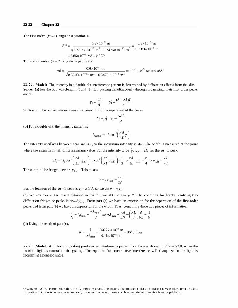
22.74. Solve: (a)
We have two incoming and two diffracted light rays at angles and and two wave fronts perpendicular to the
rays. We can see from the figure that the wave 1 travels an extra distance sinr d to reach the reflection spot.
Wave 2 travels an extra distance sinr d from the reflection spot to the outgoing wave front. The path difference
between the two waves is
1 2 (sin sin )r r r d
(b) The condition for diffraction, with all the waves in phase, is still .r m Using the results from part (a), the
diffraction condition is
sin sin 2, 1, 0, 1, 2, md m d m
Negative values of m will give a different diffraction angle than the corresponding positive values.
(c) The “zeroth order” diffraction from the reflection grating is m From the diffraction condition of part (b), this
implies 0sin sind d and hence 0 That is, the zeroth order diffraction obeys the law of reflection—the
angle of reflection equals the angle of incidence.
(d) A 700 lines per millimeter grating has spacing 61
700 mm 1 429 10 m 1429 nmd The diffraction angles
are given by
1 1 (500 nm)sin sin sin sin40
1429 nmm
m m
d
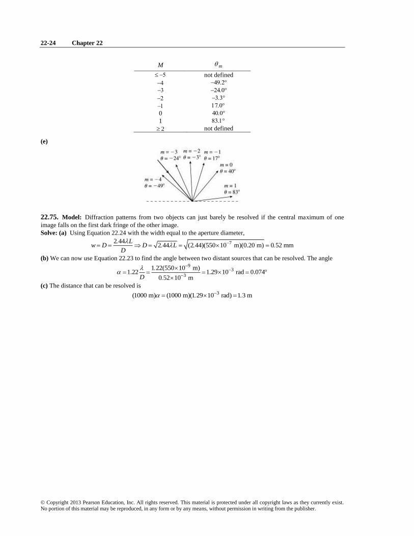
22-24 Chapter 22
© Copyright 2013 Pearson Education, Inc. All rights reserved. This material is protected under all copyright laws as they currently exist. No portion of this material may be reproduced, in any form or by any means, without permission in writing from the publisher.
M m
not defined
0
1
2 not defined
(e)
22.75. Model: Diffraction patterns from two objects can just barely be resolved if the central maximum of one
image falls on the first dark fringe of the other image.
Solve: (a) Using Equation 22.24 with the width equal to the aperture diameter,
72 442 44 (2 44)(550 10 m)(0.20 m) 0 52 mm
Lw D D L
D
(b) We can now use Equation 22.23 to find the angle between two distant sources that can be resolved. The angle 9
3
3
1 22(550 10 m)1.22 1.29 10 rad 0.074
0 52 10 mD
(c) The distance that can be resolved is 3(1000 m) (1000 m)(1 29 10 rad) 1 3 m


![User Manua Srd 16xx, 8xx English_web 0722[1]](https://img.pdfslide.us/doc/110x75/577cdc9e1a28ab9e78aaf2db/user-manua-srd-16xx-8xx-englishweb-07221.jpg)