Embed Size (px)
DESCRIPTION
Solar Power
Citation preview

CEU
191
Solar Energy
Continuing Education from the American Society of Plumbing Engineers
SEPTEMBER 2012
ASPE.ORG/ReadLearnEarn

OUR SUN Diameter: 864,000 miles (1,390,473 km)•Mass: 438 trillion, trillion, billion pounds (1.99 trillion, •trillion, billion kg)Surface temperature: 5,800°K (9,980°F)•Core temperature: 15,600,000°K (28,079,540°F) •Energy output: 386 billion, billion mega watts per sec-•ondDistance from Earth: 93,000,000 miles (149,668,992 •km)Power level at Earth: 1.4 kilowatts per square meter or •440 British thermal units (Btu) per square foot
The Sun hits Earth with enough energy every minute to meet the needs of the world’s population for an entire year.Earth is populated with more than 6.5 billion people, and the population is growing at a rapid rate, even though the rate of increase actually has been declining since the 1980s. It is estimated that the global population will reach 9 billion people around 2045. Beyond the increase in the population itself are higher rates of increase in industry to support this population and the nations that are emerging into the indus-trial age. One of the downsides to this industrial growth is its insatiable appetite for energy. Fossil resources are finite, while appetites for consumption are not.
The biggest leap in energy consumption will come from emerging economies such as China and India, where popula-tions are expected to grow by 25 percent over the next two decades and economic output and standards of living also will rise dramatically. Energy demand in China and India alone is expected to double by 2025, but the issue isn’t limited to developing countries.
Canada is the No. 1 country for use of energy per capita. The United States is in second place per capita and uses a tremendous amount of energy. The United States is home to 4 percent of the world’s population but consumes 25 percent of the world’s energy. As the more developed countries con-tinue to prosper, it is only natural that their energy needs will continue to grow accordingly.
A POSSible SOlUtiONTo reduce dependence on fossil fuels, the use of renewable energy sources must increase. Some progress is being made. For instance, solar panels are now compulsory on all new and renovated buildings in Spain as part of the country’s efforts to update its building codes and to meet the growing demand for energy.
The sun bombards Earth with an enormous amount of energy continuously. If this energy source is tapped, it could provide “free” energy.
WHAt iS SOlAR eNeRGY?The Earth bathes in a variety of energy wavelengths and par-ticles from the sun, but for the purposes of this chapter, solar energy is a renewable, environmentally friendly resource in the form of heat and light. Solar energy is available every-where on Earth, at least part of the time, and this energy is provided free of charge. It just needs to be harvested and used to provide heat, lighting, mechanical power, and electricity.
Various methods of harnessing the sun’s abundant and clean energy are available. Energy from the sun, for these purposes, can be categorized in two ways:
Thermal energy (heat)•Light energy (photovoltaics)•
Solar thermal technologies use the sun’s heat energy to heat substances (such as transfer fluids or panels) for ap-plications such as space heating, pool heating, and domestic water heating. Many products are on the market that utilize thermal energy. Often the products used for this applica-tion are called solar thermal collectors and can be mounted on the roof of a building or in some other sunny location. The sun’s heat also can be used to produce electricity on a large utility-scale by converting the sun’s heat energy into mechanical energy.
Light energy can be converted directly into electrical current through photovoltaic devices. Photovoltaics (PV) is a technology often confused with solar thermal and is in fact what many people mean when they refer to “solar en-ergy.” Photovoltaics (photo = light, voltaics = electricity) is a semiconductor-based technology (similar to the microchip) that converts light energy directly into an electric current that can be used either immediately or stored, such as in a battery or capacitor, for later use. PV panels and modules are very versatile and can be mounted in a variety of sizes and applications (e.g., on a roof or awning of a building, on roadside emergency phones, or as very large arrays consisting of multiple panels and modules). Currently they are being integrated into building materials, such as PV roofing mate-rial, which replaces conventional roofing shingles.
How much energy is needed to heat water?1 kilowatt will raise 4.1 gallons of water 100 degrees in •one hour (4.1 gph at 100˚T).1 watt is approximately 3.41 Btuh. •1 kilowatt is 3,412 Btuh.•1,000 Btuh is approximately 293 watts. •1 Btu will heat 1 pound of water 1• ˚F.
Reprinted from Plumbing Engineering Design Handbook, Volume 3. © 2011, American Society of Plumbing Engineers.
Note: In determining your answers to the CE questions, use only the material presented in the corresponding continuing education article. Using information from other materials may result in a wrong answer.
2 Read, Learn, Earn SEPTEMBER 2012
READ, LEARN, EARN
How Can Solar Help?Research shows that an average household with an electric water heater spends about 25 percent of its home energy costs on heating water. Solar water heaters offer the largest potential savings, with solar water heater owners saving as much as 50 percent to 85 percent annually on their utility bills over the cost of electric water heating. A simple payback of four to eight years can be expected on a well-designed and properly installed solar water heater. (Simple payback is the length of time required to recover the investment through reduced or avoided energy costs.)
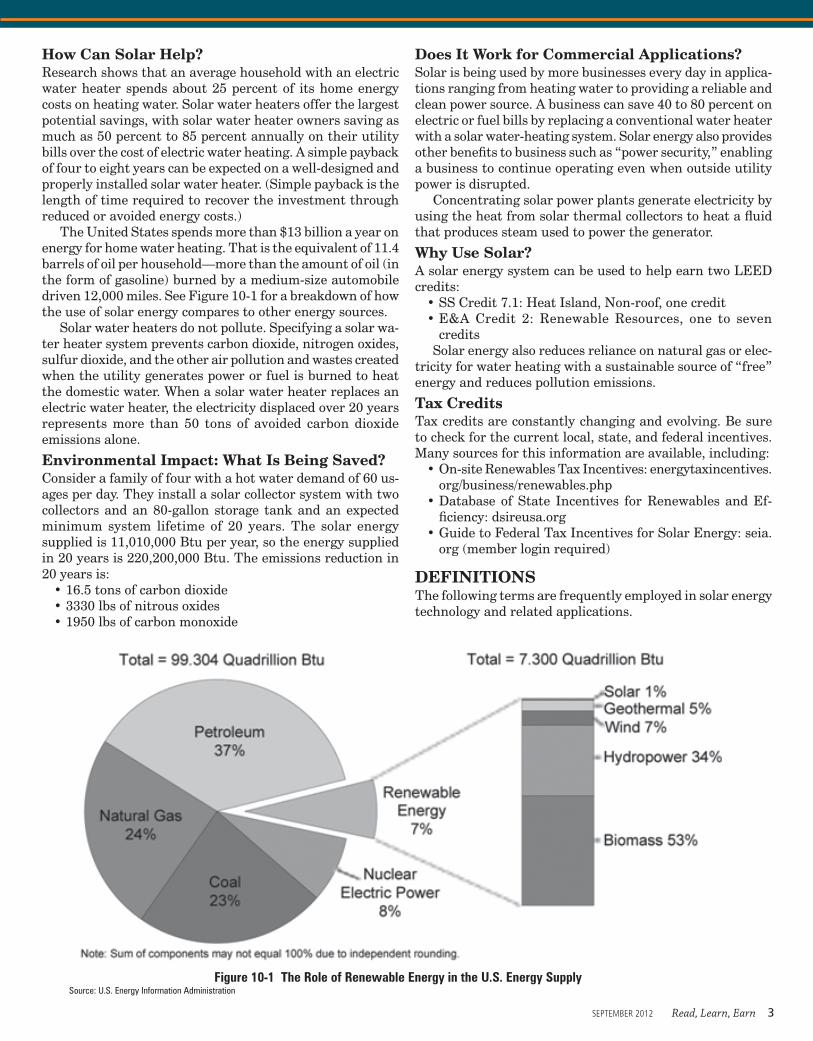
The United States spends more than $13 billion a year on energy for home water heating. That is the equivalent of 11.4 barrels of oil per household—more than the amount of oil (in the form of gasoline) burned by a medium-size automobile driven 12,000 miles. See Figure 10-1 for a breakdown of how the use of solar energy compares to other energy sources.
Solar water heaters do not pollute. Specifying a solar wa-ter heater system prevents carbon dioxide, nitrogen oxides, sulfur dioxide, and the other air pollution and wastes created when the utility generates power or fuel is burned to heat the domestic water. When a solar water heater replaces an electric water heater, the electricity displaced over 20 years represents more than 50 tons of avoided carbon dioxide emissions alone.
environmental impact: What is being Saved?Consider a family of four with a hot water demand of 60 us-ages per day. They install a solar collector system with two collectors and an 80-gallon storage tank and an expected minimum system lifetime of 20 years. The solar energy supplied is 11,010,000 Btu per year, so the energy supplied in 20 years is 220,200,000 Btu. The emissions reduction in 20 years is:
16.5 tons of carbon dioxide•3330 lbs of nitrous oxides•1950 lbs of carbon monoxide•
Does it Work for Commercial Applications?Solar is being used by more businesses every day in applica-tions ranging from heating water to providing a reliable and clean power source. A business can save 40 to 80 percent on electric or fuel bills by replacing a conventional water heater with a solar water-heating system. Solar energy also provides other benefits to business such as “power security,” enabling a business to continue operating even when outside utility power is disrupted.
Concentrating solar power plants generate electricity by using the heat from solar thermal collectors to heat a fluid that produces steam used to power the generator.
Why Use Solar?A solar energy system can be used to help earn two LEED credits:
SS Credit 7.1: Heat Island, Non-roof, one credit•E&A Credit 2: Renewable Resources, one to seven •credits
Solar energy also reduces reliance on natural gas or elec-tricity for water heating with a sustainable source of “free” energy and reduces pollution emissions.
tax Credits Tax credits are constantly changing and evolving. Be sure to check for the current local, state, and federal incentives. Many sources for this information are available, including:
On-site Renewables Tax Incentives: energytaxincentives.•org/business/renewables.phpDatabase of State Incentives for Renewables and Ef-•ficiency: dsireusa.orgGuide to Federal Tax Incentives for Solar Energy: seia.•org (member login required)
DeFiNitiONSThe following terms are frequently employed in solar energy technology and related applications.
Figure 10-1 The Role of Renewable Energy in the U.S. Energy SupplySource: U.S. Energy Information Administration
SEPTEMBER 2012 Read, Learn, Earn 3

Collector, transpired A south-facing exterior wall covered by a dark sheet-metal collector. The collector heats outside air, which is then drawn into the building’s ventilation system through perforations in the collector. They have been used for preheating ventilation air and crop drying. They are inexpensive to make, and commercially have achieved efficiencies of more than 70 percent.
Collector, trickle A flat-plate collector over which non-pressurized liquids flow
Collector efficiency The ratio of the energy collected (or absorbed) to the total solar energy incident on the collec-tor, expressed in percent
Collector subsystem That portion or assembly of the solar system used for absorbing incident solar radiation, con-verting it to thermal energy and transferring this thermal energy to a heat-transfer fluid. The collector subsystem includes the solar collectors, related piping or ducts, and regulating devices.
Collector tilt The angle above the horizontal plane at which a solar collector is mounted, in degrees
Concentrating ratio The ratio of the aperture area to the absorber of a solar collector
Concentrator A reflector, lens, or other optical device in concentration solar collectors used to focus the incident solar energy on the reduced absorber area
Conduction A heat-transfer process by which heat flows from a region of higher temperature to a region of lower temperature within a solid, liquid, or gaseous medium by molecular contact or between different media having a direct physical contact
Convection A heat-transfer process in which heat is trans-ferred from one region to another by motion of a fluid
Convection, forced A convection transfer process caused by mechanical devices, such as fans and injectors
Convection, free A convection transfer process caused by density differential within a fluid, without involvement of any mechanical devices
Cooling system The complete assembly of subsystems re-quired to convert solar energy into other forms of energy for space cooling purposes
Cover, collector The transparent material placed over the aperture or absorber area of a solar collector to provide protection from the environment and reduce thermal losses from radiation or convection
Distribution subsystem The portion of a solar system from the storage subsystem to the point of ultimate use, includ-ing the related piping or ducts and regulating devices
emittance The fraction of heat radiated by the solar col-lector, measured in percent of the absorbed energy by the panel
emissivity The ratio of the radiation emitted by a surface to the radiation emitted by a black body at the same temperature
energy transport subsystem The portion of a solar system that contains the heat-transfer media and transports the energy throughout the solar system, including related piping and regulating devices
Heat exchanger A device designed for transferring heat between two physically separated fluids
Absorber area The total heat transfer area from which the absorbed solar radiation heats the transfer fluid or the absorber media if both transfer fluid and solid surfaces jointly perform the absorbing function, in square feet
(m2)Absorber (plate) The part of the solar collector that re-
ceives the incident solar radiation energy and transforms it into thermal energy. In some cases, the heat transfer fluid itself could be the absorber.
Absorptance The ratio of the absorbed flux to the total incident flux, measured in terms of percent
Angle of incidence The angle between the line of direct solar irradiation and the perpendicular to the aperture plane, in degrees
Angle of reflection The angle between the reflected rays’ propagation direction and the perpendicular to the surface at the point of reflection, in degrees
Angle of refraction The angle between the refracted rays’ propagation direction and the perpendicular to the inter-face at the point of refraction, in degrees
Area, aperture The maximum projected area of a solar collector through which un-concentrated solar radiant energy is admitted, in square feet (m2)
Area, gross collector The maximum projected area of a solar collector module including any integral mounting devices, in square feet (m2)
Auxiliary energy subsystem A configuration of equip-ment and components, utilizing conventional energy sources, to supplement the output of the solar system
Collector A device used to absorb the sun’s energyCollector, concentrating A collector that uses reflectors,
lenses, or other optical devices to concentrate the radi-ant solar energy passing through the aperture onto an absorber of which the surface area is smaller than the aperture area. Parabolic trough-shaped reflectors concen-trate sunlight onto an absorber or receiver to provide hot water and steam, usually for industrial and commercial applications.
Collector, flat plate A non-concentrating collector in which the absorbing surface is essentially planar and usually with approximately the same area as the aperture. Small tubes run through the box and carry fluid—either water or another fluid such as an antifreeze solution. The tubes attach to a black absorber plate. As heat builds up in the collector, the fluid passing through the tubes is heated. The hot transfer liquid goes to a storage tank, and water is heated as it passes through a tube inside the storage tank full of hot fluid. This is the most common type of collector for solar water heating.
Collector, evacuated tube (vacuum tube) A collector consisting of rows of parallel transparent glass tubes, each containing an absorber and covered with a selective coating. Sunlight enters the tube, strikes the absorber, and heats the liquid flowing through the absorber. These collectors are manufactured with a vacuum between the tubes, which helps them achieve extremely high tempera-tures (170–350˚F). Their high efficiency makes them a good choice for commercial uses.
4 Read, Learn, Earn SEPTEMBER 2012
READ, LEARN, EARN: Solar Energy

Heat pump A device designed to simultaneously or alter-nately use the heat extracted at a low temperature and the heat rejected at a high temperature for cooling and heating purposes
Heat-transfer medium A fluid used in the transport of thermal energy
Heating and cooling system The complete assembly of subsystems required to convert solar energy into ther-mal energy and utilize this energy, in combination with auxiliary energy (if necessary), for combined heating and cooling purposes
Heating system The complete assembly of subsystems required to convert solar energy into thermal energy and utilize this energy, in combination with auxiliary energy (if necessary), for heating purposes
Hot water system The complete assembly of subsystems required to convert solar energy into thermal energy and utilize this energy, in combination with auxiliary energy (if necessary), for service water heating
infrared radiation Radiation with wavelengths greater than 70 millionths centimeter (7,000 Angstrom units) but less than radio waves, about 5.5 centimeters
irradiation (insolation), instantaneous The quantity of solar radiation incident on a unit surface area in a unit of time, in Btuh per square foot (W/m2)
insolation The solar radiation striking the surface of Earth or another planet. Also the rate of delivery of solar radia-tion per unit of horizontal surface (see irradiation).
Performance factor efficiency The ratio of the useful output capacity of a system to the input required to obtain it
Radiant emittance (exitance) The quotient of the radi-ant flux leaving an element of the surface containing the point by the area of that element
Radiant flux Power emitted, transferred, or received in the form of electromagnetic waves or photons
Radiant intensity The quotient of the radiant flux emitted by a source (or by an element of a source in an infini-tesimal cone containing the given direction) by the solid angle of the cone
Radiation The heat-transfer process by which heat flows from a body at a higher temperature to a body at a lower temperature, when the bodies are separated in space or when a vacuum exists between them (emission or transfer of energy in the form of electromagnetic waves or photons)
Selective surface A coating applied to a solar collector, or its absorber area, having a high absorptance and a low emittance
Solar absorptance The fraction of the solar irradiance that is absorbed
Solar constant The solar radiation intensity that is incident on a surface normal to the sun’s rays, outside the Earth’s atmosphere, at a distance from the sun equal to the mean distance between the Earth and the sun. The accepted valued of the solar constant is equal to 428.8 Btuh per square foot (1,353 W/m2).
Solar degradation The process by which exposure to sun-light deteriorates the properties of materials
Solar energy The photon (electromagnetic) energy origi-nating from the sun
Solar system Equipment and components arranged in a manner to collect, convey, store, and convert solar en-ergy
Solar system, air A solar system that uses air as the pri-mary heat-transfer fluid
Solar system, active A solar system in which the inci-dent solar radiation is absorbed by the solar collectors, transferred to an independent thermal storage unit, and distributed to the point of ultimate use by means of mechanical devices powered by conventional fuels (i.e., pumps and fans)
Solar system, closed A solar system that has a completely enclosed collector subsystem circulating the heat-transfer fluid under pressure above atmospheric and shut off from the atmosphere, except for an expansion tank
Solar system, liquid A solar system that uses liquid as the primary heat-transfer fluid
Solar system, open A solar system that exchanges heat directly with the end-use application
Solar system, passive A solar system in which solar energy utilization becomes the prime objective of engineering and architectural design. The flow of heat is achieved by natural convention, conduction, and radiation
Solar system, thermosyphon A passive solar system in which fluids circulate due to their temperature differen-tials, rather than under the influence of pumps or fans
Storage device (thermal) The containers, including all contents of such containers, used for storing thermal energy. Heat-transfer fluid, heat exchangers, flow-control devices, valves, baffles, etc. that are integral with the thermal storage container are regarded as parts of the storage device.
Storage medium (thermal) The material in the thermal storage device, independent of the containing structure, in which the major portion of the energy is stored
Storage subsystem The assembly of components neces-sary for storing energy so it can be used when required, including all related regulating devices used in connec-tion thereof
Subsystem A major, separable, and functional assembly or portion of a system
thermosyphon The natural circulation of a fluid caused by temperature differentials within the fluid system
transfer fluid, heat The medium that flows through a solar collector and carries the absorbed energy away from the collector
transmittance The ratio of flux transmitted through a material to the incident flux
Ultraviolet radiation Radiation with wavelengths from 180 to 400 µm (Angstrom units)
Watt An energy per second unit (1 watt = 1 joule per sec-ond)
SOMe QUiCK eStiMAtiNG CAlCUlAtiONSFollowing are some estimates that can be used in calcula-tions:
SEPTEMBER 2012 Read, Learn, Earn 5

One direct hour of sunlight = 1 kilowatt-•hour per square meter 1 kilowatt-hour = 3,412 Btu•1 gallon of #2 fuel oil = 150,000 Btu•1 square meter = 10.6 square feet•One 4x8 collector (approximately) = 3 •square metersOne 4x8 collector (approximately) = •12–15 kilowatt-hours per day
QUiCK COSt COMPARiSONSTables 10-1 and 10-2 illustrate two simple spreadsheets used to estimate costs for differ-ent solar systems. Many variables and other project-specific items are not taken into ac-count within these calculations, so the actual cost of a system will be higher. This is only to provide a general idea of the magnitude of the differences among the systems.
A plethora of information is available via the Internet, books, and magazines to assist in the design of solar systems. Some of this information can be found within this chapter; however, a more complete understanding will come only through further research.
SYSteM SiZiNG RUleS OF tHUMbApproximately 440 Btuh per square foot of energy generated by the sun could potentially reach the Earth (see Figure 10-2). Of that potential energy, 30 to 60 percent is lost in the journey through the atmosphere, and 170 to 315 Btuh per square foot eventually reaches the surface.
For example, Chicago receives 1,260 to 1,575 Btu per square foot per day of energy from the sun. For optimum output, panels should be installed at a 45-degree angle and face south. The optimum output from a panel is roughly 220 Btuh per square foot. The amount of energy disbursed by the sun fluctuates with sunspot ac-tivity and solar storms, but the maximum available energy from a collector is generally considered to be 220 Btuh per square foot.
SOlAR iRRADiAtiON COlleCtiON MetHODSThe solar collector is the main component of the active solar irradiation collection subsystem (see Figure 10-3). It is the device that absorbs the incoming solar energy, converts it to heat, and transfers this heat to a fluid (liquid or air) flowing through the solar collector. To absorb or collect this energy, several different panel or collector styles are available, which can be classified into three general categories:
Flat-plate solar collectors: Non-concentrating collectors •in which the absorbing surface is essentially planar and is approximately equal to the gross collector areaConcentrating solar collectors: Collectors that use •mirrors, lenses, reflectors, or other optical devices to
concentrate the radiant solar energy passing through the collector’s aperture onto an absorber of which the absorber area is smaller than the aperture areaVacuum tube solar collectors: Collectors that use sealed •vacuum tubes, which operate via a self-contained vapor reaction to heat a condenser at the end of the tube and transmit heat through a small, integral heat exchanger through a manifold through which the fluid (water and/or glycol) circulates
Flat-plate Solar CollectorsA typical flat-plate solar collector unit consists of the follow-ing basic elements:
One or more collector covers (glazing), transparent to •the incoming incident solar radiation and opaque to the infrared radiation from the absorber plate. These are intended to protect the absorber plate from the environment and to act as a shield to reduce radiative and convective heat losses from the absorbing surface. Glass and plastic typically are the materials utilized for collector covers.An absorber plate (surface), usually incorporating chan-•nels (conduits) containing the heat-transfer fluid, used to absorb the sun’s incident radiation and to transfer
Table 10-1 Solar Cost Comparison, Method A
Solar Collector (Flat Plate) Cost Total Cost
Total kilowatts Watts per square foot
Square feet Cost per watt
200 63 3,200 1 $200,000
PV Panel Cost Total Cost
Total kilowatts Watts per square foot
Square feet Cost per watt
200 16 12,500 10 $2,000,000
PV Roof Material Cost Total Cost
Total kilowatts Watts per square foot
Square feet Cost per watt
200 4 50,000 10 $2,000,000
Table 10-2 Solar Cost Comparison, Method B
Solar Collector (Flat Plate) Cost Total Cost
Square feet Watts per square foot
Total kilowatts Cost per watt
3,200 63 200 1 $200,000
PV Panel Cost Total Cost
Square feet Watts per square foot
Total kilowatts Cost per watt
12,500 16 200 10 $2,000,000
PV Roof Material Cost Total Cost
Square feet Watts per square foot
Total kilowatts Cost per watt
50,000 4 200 10 $2,000,000
6 Read, Learn, Earn SEPTEMBER 2012
READ, LEARN, EARN: Solar Energy

the energy (heat) to the fluid medium in the channels. Metals and plastics have been used in the construction of absorber plates, which are sometimes coated with a selective surface finish having high-absorptivity and low-emissivity factors. Extreme care should be exercised when selecting a metal for the construction of the ab-sorber plates. Each material has its own characteristics, which may induce galvanic corrosion. Also, it should be noted that the thermal conductivities of plastics are less than those of metals. Therefore, plastic materials should be limited to low-temperature applications (e.g., swim-ming pool heating).Thermal insulation, placed behind the absorber plate •and channel assembly and surrounding the perimeter of the solar collector module, used to reduce heat losses and increase radiation on the absorber plates and chan-nel assemblyA backplate, which is placed behind the insulation and •acts as a reflector surface, used to reduce heat losses and increase radiation on the absorber plates and channel assembly. Aluminum and foil reflectors are the materials generally used in the construction of backplates.Headers (manifolds), which are used to convey the •absorbed energy. To ensure steady flow conditions, the headers should have a cross-sectional area larger than the area served by the channels. Metals and plastics are the materials commonly utilized in the construction of the headers.A frame, including angle-fixing and mounting devices, •etc., enclosing the complete solar collector module
Many configurations of flat-plate solar collectors are avail-able. For example, the absorber plate/channel assembly could be of fin design or corrugated sheets, with channels above, channels below, or channels as integral parts with the absorber plate. Also, flat-plate modules used in swimming pool heat-ing applications (low temperature/high water volume) do not normally require a covers, backplate, or insulation by design. The absorber plate, channel assembly, and headers are the only elements necessary.
The amount of incident solar energy (radiation) collected is governed by the following criteria:
Transmittance of the collectors covers, which should •exceed 90 percent of the solar spectrumAbsorptivity factor of the absorber plate to the incident •solar radiation, which should exceed 95 percentEmissivity factor of the absorber plate in the infrared •spectrumThermal resistance between the absorber plate and the •heat-transfer mediumReduction of the conductive, convective, and radiative •heat (thermal) losses from the panel, which depends on the operating temperature of the panel, usually ranging from 90–210˚F (32.2–98.8˚C) or higher
The most widely used measure of the performance of flat-plate collectors is thermal efficiency (q), which is defined as the ratio of delivered heat to the incident solar radiation. However, it should be noted that the thermal efficiency of a flat-plate solar collector is not a sufficiently descriptive index to select a unit module. The most important proper-
ties of a flat-plate solar collector are the collector operating temperature, type of collector surface, and type and number of collector covers.
The steps for determining the thermal efficiency of a flat-plate solar collector, including the necessary data, are as follows:
To calculate the incident beam component of insolation •normal to the collector (Ib,coll) and the diffuse com-ponent of insolation (Ih,d), obtain the insolation on a horizontal surface (Ih), cloud cover (CC), solar altitude angle (a), collector tilt angle (E), and latitude (L).To calculate the absorbed radiation (Icoll), obtain the •number of collector covers (n).To calculate the delivered energy to working fluid (qa), •obtain the wind speed (v) in knots (m/s), collector temper-ature (Tcoll) in ˚R, and collector physical properties.
The following equations should be used in calculating the thermal efficiency:
Equation 10-1lb,coll = Ih,b(cos i)/sin a
Equation 10-2Ih,d = 0.78 + (1.07) a + (6.17) CC
Equation 10-3Icoll = Ib,coll(l – Pbn) αs,b + Ih,d (l – Pd) αs,d
Equation 10-4qa = Icoll – Lt
Equation 10-5η = q/(Ib,coll + Ih,d)
where:Ib,coll = Incident beam component of insolation normal to
the collector surface, Btuh per square foot (W/m2)Ih,b = Horizontal beam component of insolation, Btuh per
square foot (W/m2)i = Angle of incidence, degreesa = Solar altitude angle, degreesIh,d = Diffuse component of insolation, Btuh per square
foot (W/m2)CC = Cloud cover, tenths (1/10) of sky coveredIcoll = Absorbed radiation, Btuh per square foot (W/m2)Pbn = Reflectance from several covered sourcesαs,b = Absorptance (beam) Pd = Diffuse reflectanceαs,d = Absorptance (diffuse) qa = Energy delivered to working fluid, Btuh per square
foot (W/m2)Lt = Thermal losses of collectors, Btuh per square foot (W/
m2)η = Thermal efficiency, percent
Concentrating CollectorsThe advantages of using concentrating collectors in solar systems have long been recognized. Several thermal processes require much higher temperatures than those that can be reached by flat-plate solar collectors; therefore, concentrators must be employed. However, although many concentrating solar systems have successfully operated over the years, the
Table 10-1 Solar Cost Comparison, Method A
Solar Collector (Flat Plate) Cost Total Cost
Total kilowatts Watts per square foot
Square feet Cost per watt
200 63 3,200 1 $200,000
PV Panel Cost Total Cost
Total kilowatts Watts per square foot
Square feet Cost per watt
200 16 12,500 10 $2,000,000
PV Roof Material Cost Total Cost
Total kilowatts Watts per square foot
Square feet Cost per watt
200 4 50,000 10 $2,000,000
Table 10-2 Solar Cost Comparison, Method B
Solar Collector (Flat Plate) Cost Total Cost
Square feet Watts per square foot
Total kilowatts Cost per watt
3,200 63 200 1 $200,000
PV Panel Cost Total Cost
Square feet Watts per square foot
Total kilowatts Cost per watt
12,500 16 200 10 $2,000,000
PV Roof Material Cost Total Cost
Square feet Watts per square foot
Total kilowatts Cost per watt
50,000 4 200 10 $2,000,000
SEPTEMBER 2012 Read, Learn, Earn 7

economics have played a very important role. The flat-plate solar collectors that do not require sun-tracking devices have taken predominance because of their lower manufacturing and installation costs.
Some of the advantages of concentrating collectors over flat-plate collectors are as follows:
The reflecting surfaces require less material and are •structurally simpler than flat-plate units.The absorber area is significantly smaller than that of •a flat-plate unit. Therefore, the radiation intensity is much greater.The working fluid can attain higher temperatures.•Little or no antifreeze solution is required. •Some of the disadvantages are:•The concentrating collectors only collect on the direct •component of the radiation.Maintenance and operating costs are higher.•Reflecting surfaces may deteriorate.•The diffuse component of radiation plays a very small •role in the heating of the fluid.
Among the concentrating collector systems, particular notice should be paid to the following.Stationary Reflector Tracking Absorber The stationary reflector tracking absorber (SRTA) system was developed by W. Gene Steward (Environmental Consult-ing Services in Boulder, Colorado) and J. L. Russel (General Atomics in San Diego, California). The Steward SRTA is a compound curvature collector, whereas the Russel SRTA is a single curvature collector. Both SRTA systems are for electric power generation (photovoltaic application). This collector system is based on optical principles showing that, regardless of the position of the sun, a fixed mirror can focus
most of the incoming solar radiation on a line parallel to the rays of the sun.
The size of the SRTA absorber is based on the width of the solar image and the maximum absorber length necessary to capture all reflected rays.
A theoretical average geometric concentration factor (Fc) is defined as the ratio of the projected surface area of a concentrator (Ap) to the area of the sun’s image (Ai) on the collecting surface. The temporal average for a day is obtained from the following relation:
Equation 10-6
F̄c =Ap = I ∫°
θ1 F̄cdiAi θ1
where: θ = Incidence angle i at mirror sunrise
The value of the concentration factor obtained from Equa-tion 10-6 does not take into account surface irregularities in the reflecting mirror. In actual practice, the absorber may be five or six times greater than the theoretical value to compen-sate for surface irregularities in the reflecting mirror and to absorb some diffuse radiation on cloudy or hazy days.
When comparing a flat-plate collector system and a SRTA system, it is imperative that a complete system analysis be performed. One does not pay for the surface area, but rather for the amount of heat or useful energy delivered per unit surface area. A cost comparison between a flat-plate collector and a SRTA system can be made on the following:
Equation 10-7
( Afp ) (cost per ft2 of flat-plate collector)ηfp
Equation 10-8πd2
a × cost per ft2 of mirror surfaceηSRTA frontal area per mirror area
where:Afp = Surface area of flat-plate collector, square feet (m2)ηfp = Diameter of flat-plate collector, percentda = Diameter of aperture area of SRTA collector, feet (m)ηSRTA = Efficiency of stationary reflector tracking absorber
collector, percent
Figure 10-3 How Solar Energy Is Collected
Figure 10-2 Amount of Sun’s Energy that Reaches the Earth
8 Read, Learn, Earn SEPTEMBER 2012
READ, LEARN, EARN: Solar Energy

The cost of the SRTA absorber is prorated on a mirror sur-face area basis. For complete cost comparisons, the cost of the entire solar system for each design should be considered.Compound Parabolic Concentrator The compound parabolic concentrator (CPC) system was de-veloped by Roland Winston (Argonne National Laboratories in Argonne, Illinois). The CPC is a non-tracking solar collec-tor consisting of two sections of a parabola of second degree, symmetrically located about the mid-plane of a collector. The two sections form a single curvature solar concentrator with an angular acceptance of 2 (θmax). The acceptance depends on the ratio of aperture area (Wc) to the absorber area (Wa) and is expressed by the relation:
Equation 10-9
θmax = sin-1( Wa )Wc
whereθmax = Maximum acceptanceWa = Absorber area, square feet (m2)Wc = Aperture area, square feet (m2)
The concentration ratio (CR) of the CPC system can be determined by the expression:
Equation 10-10
CR = WeWa
This collector system should be oriented in an east-west direction and tilted toward the south at an angle (E) from the horizontal plane. When the angle (y) is less than Amax, the CPC collector accepts both direct and diffuse components of sunlight. When the angle is greater than Amax, the CPC collector accepts only diffuse sunlight over the portion of the aperture area equal to the absorber area. Beam insolation incident on a CPC collector outside the acceptance angle does not reach the absorber area, but is reflected from the side walls back through the aperture.
The theoretical depth of the CPC collector (dcoll) depends on the concentration ratio and is defined by the expres-sion:
Equation 10-11
dcoll = Wa[ (CR+1) ][(CR−1)½]2
In actual practice, it has been found advantageous to use a value of dcoll that is one-third smaller than that calculated from Equation 10-11.
SYSteM SiZiNG AND CAlCUlAtiONSSeveral computer simulation design programs are cur-rently available for sizing solar-assisted service water- and space-heating systems. In this chapter, the f-chart method developed by the University of Wisconsin is used for sizing such systems. The f, expressed in terms of percent, is the fraction of the heating load supplied by solar energy or the percentage of the total heating load furnished by the solar system. These design charts are calculated utilizing double-glazed, selective-surface collector panels. Other types of solar
collectors (e.g., single-glazed selective surface; double-glazed non-selective surface; single-glazed non-selective surface) could be used. However, the data for developing the charts must be varied accordingly.
The following data is required when employing the f-chart method in the sizing procedures: number of degree days, ambient temperature, building heat loss (if space heating is being considered), hot water demand, collector orientation, and design parameters of the system.
Solar-assisted Service Water HeatingSolar-assisted service water-heating systems generally provide maximum savings when the system is designed to deliver 45 to 70 percent of the load (f = 45 to 70 percent). To determine the amount of energy required to heat the service water, the following information is needed:
Hot water supply temperature•Cold water supply temperature•Daily hot water demand•
To meet the requirements set forth in the Federal Housing Administration’s Minimum Property Standards, the hot water supply temperature must be 140˚F (60˚C) minimum. This also helps reduce waterborne pathogens such as Legionella. Depending on the season and geographical location, the cold water supply temperature may vary from 40˚F to 70˚F (4.4˚C to 21.1˚C), although it is possible to have lower or higher tem-peratures. This should always be considered when calculating water heating or cooling applications.
Although many system types, applications, and design techniques may be considered for various service water-heating requirements, a few basic guidelines should be followed in all cases.
Systems should be designed to be as simple and as fea-•sible as possible for each specific application.Match system design to load patterns and magnitude, •and avoid misuse of design rules of thumb.Consider system efficiency, as well as collector effi-•ciency.All phases of a system’s control cycle should be examined •for potential operational and energy waste problems.Plan for component expansion, movement, and service •during system design.
Sizing Procedure for Service Water HeatingThe following steps should be followed when sizing a solar-assisted service water-heating system.
1. Determine the daily hot water demand.
2. Determine the hot water supply temperature. Generally, this temperature can be taken as 140°F (60°C).
3. Determine the cold water supply temperature. This temperature typically ranges from 40°F to 70°F (4.4°C to 21.1°C), depending on the season and geographical loca-tion. In the absence of such data, assume this temperature to be 45°F (7.2°C) as a year-round average.
4. Determine the closest weather station location and pre-pare an f-chart. A sample f-chart is illustrated in Figure 10-4. Data on degree days and percent f at the collection point may be obtained from the ASHRAE Handbook of Fundamentals and the Solar Decision Handbook.
SEPTEMBER 2012 Read, Learn, Earn 9
5. Determine the percent f to be delivered by the solar system.
6. Using the f-chart, determine the size of the collector array (in square feet [m2]) required to provide the de-sired percent f. The following calculations will provide approximate values, as indicated.To determine the flow rate of the heat-transfer fluid in •the collector loop, multiply the collector area by 0.039 (0.027 in SI units). To determine the maximum heat transfer to the heat •exchanger, multiply the collector area by 225 (709.6 in SI units).To determine the size of the preheater tank, multiply •the collector area by 2 (81.4 in SI units).
7. Determine the pump head in the collector loop.
8. Determine the pump head in the storage loop.
9. Determine the volume of heat-transfer fluid required.
10. To determine the size of the expansion tank needed, multiply the volume of the heat-transfer fluid by 10 percent.
Figures 10-5 and 10-6 illustrate typical installations of solar-assisted service water-heating systems.
Example 10-1
Location: Memphis, Tennessee•Family of four, standard kitchen and bathroom•
Step 1: Determine the daily hot water demand, approxi-mated as 15 gallons per person per day (56.8 L per person per day). For four persons, the daily hot water demand would be 60 gallons (227.2 L).
Step 2: Determine the hot water supply temperature. To meet FHA requirements, this temperature should be 140°F (60°C).
Step 3: Determine the cold water supply temperature. This temperature can be assumed to be 45°F (7.2°C).
Step 4: Develop an f-chart. See Figure 10-7.If 60 percent of the load is to be supplied by the solar
system, approximately 35 square feet (3.3 m2) of collector area is required. The flow rate of the heat-transfer fluid in the collector loop would be 35 ft2 × 0.039 = 1.4 gpm (3.3 m2 × 0.027 = 0.09 L/s). The maximum heat transfer to the heat exchanger would be 35 ft2 × 225 = 7,875 Btuh (3.3 m2
× 709.6 = 2,341.7 W).Sizing Procedure for Service Water and Space HeatingThe following steps should be followed when sizing a combined solar-assisted service water- and space-heating system.
1. Calculate the building heat loss. ASHRAE-recommended methods should be used.
2. Determine the building’s design temperature. This tem-perature is the lowest outside air temperature, in °F (°C), at which the building must be heated to 65°F (18.3°C).
3. Calculate the building’s design load. This load is the product of the building’s heat loss and the building’s design temperature.
4. Determine the daily hot water demand, hot water sup-ply temperature, and cold water supply temperature. Follow steps 1, 2, and 3 given for service water-heating systems.
5. Determine the closest weather station and prepare an f-chart.
6. Determine the percent f to be delivered by the solar system.
7. Determine the size of the collector array, in square feet (m2), required to provide the desired percent f using the chart.
8. Determine the flow rate of the heat-transfer fluid in the collector loop, maximum heat-transfer fluid in the collec-tor loop, maximum heat transfer to the heat exchanger, and the size of the storage tank. Use step 6 of the service water-heating procedure.
9. Determine the pump head in the collector loop and stor-age loop.
10. Determine the pump head for the entire heat-delivery loop (preheater, to and from storage tank, etc.).
11. Determine the fan coil size. The output of the fan coil should be equal to or greater than the building’s design load.
12. Select a heat pump with an output equal to or greater than the building’s design load.
13. Select an auxiliary heater with an output equal to or greater than the building’s design load.
Figure 10-8 provides illustrations of combined systems.
Keys to SizingBuilding load: What is the daily water demand?•Building occupancy: On average, how many days per •week is the building occupied? Location•Safety measures/devices•
Example 10-2
An apartment building occupied at all times has 64 units using 30 gpd each (1,920 gpd total). If one 30-square-foot panel generates 30,000 Btu per day in the summer, how many panels are needed?
30,000 Btu / 8.34 pounds per gallon / (120°F – 60°F) = •60 gallons at a 60°F rise per panel1,920 gpd / 60 = 32 solar panels•
Example 10-3
For the same apartment building, how much storage is needed?
30,000 Btu / 8.34 pounds per gallon / (150°F – 60°F) = •40 gallons at a 90°F rise per panel40 x 32 panels = 1,280 gallons of storage•
Keys to PerformanceWhen laying out the panels, consider the following to ensure peak performance.
What is the flow rate through a panel?•How do off-peak loads affect temperature and control?•What temperature does the sensor see?•
10 Read, Learn, Earn SEPTEMBER 2012
READ, LEARN, EARN: Solar Energy

How big is the piping (heat loss, installation cost)?•How efficient is the system?•
PANel lAYOUtS AND PiPiNG ARRANGeMeNtSPanels in Parallel/Arrays in Parallel
32 panels = Eight arrays (see Figure 10-9)•1–1.5 gpm per panel = 32–48 gpm total•2–2½-inch pipe•Vents on cold water•Sensor low at end•10°F band in summer; 2–4°F in lower months•
Panels in Series/Arrays in Parallel32 panels = Eight arrays (see Figure 10-10)•1–1.5 gpm per panel = 32–48 gpm total•2–2½-inch pipe•One vent on hot water•Sensor high at end•10°F band in summer; 2–4°F in lower months•
Panels in Series/Arrays in Series32 panels = Eight arrays (see Figure 10-11)•1–1.5 gpm per panel = 8–12 gpm total•1–1¼-inch pipe•Vents at high points•Sensor high at end•40°F band in summer; 10–20°F in lower months•
illustrationsFigures 10-12, 10-13, and 10-14 illustrate a dual water heater installation with one storage tank, a dual water heater installation with two storage tanks, and a detail of the solar panel array.
SPeCiFiCAtiONSThe specifications are an important part of any system design. Several formats are used today. Always coordinate and verify the specification format that is to be used for a project.
In the current Construction Specifications Institute (CSI) format, plumbing is found in the 220000 sections. Some of the sections that may be included in a solar water heater system specification follow. Note that a system may require sections other than those listed. These are only listed as an example.
220500 Common Work Results for Plumbing•22053 General Duty Valves for Plumbing•220529 Hangers and Supports for Plumbing•220533 Freeze Protection for Plumbing Piping •220548 Vibration and Seismic Controls for Plumbing •Piping and Equipment220553 Identification for Plumbing Pipe and Equip-•ment230993.13 Controls Point List•
Regardless of the format used, the basic objectives and requirements are the same. The following may serve as a guideline to writing specifications for a solar system.
CollectorsManufacturer and model number•Number of covers•Performance characteristics•Testing agency and test method followed•Stagnation conditions•Recommended flow rate•Operating temperatures•Pressure drop at maximum flow rate•Materials•Glazing•Gaskets•Insulation•Absorber plate•Selective coating•Recommended heat-transfer fluid•Physical dimensions•Module size•Aperture area•Weight•Expected collector life•Warranty•
Heat exchangersManufacturer and model number•Construction•Recommended heat-transfer fluid•Warranty•Expected life•Materials•Physical dimensions•Performance•Testing agency and test method followed•Operating conditions•Flow rate•
SQUARE FEET (M2) OF COLLECTOR
50(4.7)
100(9.3)
150(13.9)
200(18.8)
250(23.2)
10
20
30
40
50
60
70
80
90
100
60 GALL
ONS (22
7.1 L)
80 GALLONS (3
02.8 L)
120 GALLONS 454.28 L)
% F
Figure 10-4 Sample f-chart, Service Water Heating Application
SEPTEMBER 2012 Read, Learn, Earn 11

Pressure drop•Temperature•Pressure•Pumps•Manufacturer and model number•Motor coupling•Mechanical seal•Warranty•Estimated life•
Pump body and impeller MaterialGasketing materials•Motor voltage•Amperage•Operating conditions•Flow rate•Pressure drop•Temperatures•Pressure•Pump curves•Flange connections•Preheater tanks•Manufacturer and model number•Storage capacity•Body material•Lining•Insulation•Plumbing connections•Jacket•Sacrificial anode•Physical size•Auxiliary heater•Pressures•Weight•Warranty•Estimated life•Operating temperatures•
Storage tanksManufacturer and model number•Capacity•Operating temperatures•Storage medium•Freezing precautions•Lining•Working pressure•Materials of construction•Insulation•Plumbing connections•Jacket•Physical dimensions•Pressures•Weight•Drain valves•Manhole•Live and dead loads•Warranty•Estimated life•
SOLAR RADIATION
1. SOLAR COLLECTORS2. CIRCULATING PUMP3. TEMPERATURE/PRESSURE
RELIEF VALVE4. PUMP CONTROLLER5. SENSOR: COLLECTOR
TEMPERATURE6. SENSOR: TANK TEMPERATURE
7. CHECK VALVE8. HEAT EXCHANGER9. STORAGE TANK10. AUXILLARY HEAT SOURCE11. WATER SUPPLY12. TO BUILDING
1
3
9
12
11
10
3
LEGEND
7
5
8
64
2
Figure 10-6 Pump Circulating System, Service Water Heating Application, Direct
SOLAR RADIATION
1. SOLAR COLLECTORS2. TEMPERATURE/PRESSURE
RELIEF VALVE3. STORAGE TANK4. HEAT EXCHANGER
5. WATER SUPPLY6. AUXILLARY HEAT SOURCE7. TO BUILDING
1
2
4 3
7
5
6
2
LEGEND
Figure 10-5 Thermosyphon System, Service Water Heating Application, Indirect
12 Read, Learn, Earn SEPTEMBER 2012
READ, LEARN, EARN: Solar Energy

Controls•Manufacturer and model number•Differential thermostat•Sensor•Available functions•Power input•Approvals and listings•Ground provisions•Warranty•Estimated life•
Heat PumpsManufacturer and model number•Pump type•Rated heat and cooling output•Rated heat and cooling coefficient of performance and •energy-efficiency ratioAuxiliary heaters•Filters•Operating voltage and amperage•Condenser coil operating range and flow rate•Physical dimensions•Weight•Operating sequence•Warranty•Estimated life•
insulationManufacturer and type (material)•Heat transfer characteristics/thickness•Flame spread and smoke-developed characteristics•Vapor barrier/cover•Method of application•Warranty•
ADDitiONAl ReADiNG AND OtHeR ReSOURCeSA bounty of information is available to assist in the de-sign of solar systems. A more complete understanding will come through further research.
The Solar Hydrogen Civilization• by Roy McAlisterSolar Energy Industries Association: seia.org •Energy Star: energystar.gov •Internal Revenue Service: irs.gov •TIAP: energytaxincentives.org •Solar Rating Certification Corporation (SRCC): •
solar-rating.org U.S. Department of Energy, Energy Efficiency and •
Renewable Energy: eere.energy.gov Solar and Sustainable Energy Society of Canada: •
sesci.ca Canadian Solar Industries Association: cansia.ca •Kortright Centre for Conservation: kortright.org •
ReFeReNCeSASHRAE Handbook — 1989 Fundamentals, American Society of Heating, Refrigerating, and Air-Conditioning Engineers, Atlanta, GA.
Duffie, J. A. and Beckman, W. A., Solar Energy Thermal Processes, Interscience Publishers, New York, NY, 1974.
Kreider, J. F. and Kreith, J., Solar Heating and Cooling, McGraw-Hill, New York, NY, 1975.
ASHRAE 93: Standard of Testing to Determine the Performance of Solar Collections, American Society of Heating, Refrig-erating, and Air-Conditioning Engineers, Atlanta, GA, 1986.
Montgomery, R. H. and Budnick, J., Solar Decision Book, Dow Coming Corporation, Midland, MI,1978.
ASHRAE 90A: Energy Conservation in New Building Design, American Society of Heating, Refrigerating, and Air-Con-ditioning Engineers, Atlanta,GA, 1975.
Beckman, W. A., Klein, S. A., and Duffie, J. A., Solar Heating Design by the f-Chart Method, Wiley-Interscience, New York, NY, 1977.
Kreider, J. F., The Solar Heating Design Process, McGraw-Hill, New York, NY, 1982.
Solar Design Workbook, Solar Energy Research Institute, Golden, CO, 1981.
Solar Energy System Design, American Society of Plumbing Engineers, Westlake, CA, 1980.
Tully, G. F., Solar Heating Systems, McGraw-Hill, New York, NY, 1981.
U. S. Department of Energy, Active Solar Energy System Design Practice Manual, Solar/0802-79/01, NITS, Springfield, VA, 1979.
ASHRAE Handbook — 1988 Equipment, American Society of Heating, Refrigerating, and Air-Conditioning Engineers, Atlanta, GA.
ASHRAE Handbook — 1987 Systems and Applications, Ameri-can Society of Heating, Refrigerating, and Air-Conditioning Engineers, Atlanta, GA.
Solar Water Heater’s: A Buyer’s Guide” Natural Resources Canada, Ottawa: Minister of Supply and Services, 1987.
SQUARE FEET (M2) OF COLLECTOR
50(4.7)
100(9.3)
150(13.9)
200(18.8)
250(23.2)
10
20
30
40
50
60
70
80
90
100PE
RCEN
T OF
LOAD
PRO
VIDE
D BY
SO
LAR
SYST
EM, %
F
Figure 10-7 f-chart for Memphis, Tennessee
SEPTEMBER 2012 Read, Learn, Earn 13

SOLAR RADIATION
1
3
9
12
10
31. SOLAR COLLECTORS2. CIRCULATING PUMP3. TEMPERATURE/PRESSURE RELIEF VALVE4. PUMP SWITCH5. SENSOR: COLLECTOR TEMPERATURE6. SENSOR: TANK TEMPERATURE7. HEAT EXCHANGER8. STORAGE TANK9. WATER SUPPLY10. AUXILLARY HEAT SOURCE11. HOT WATER TO BUILDING12. FORCED AIR FURNACE13. HEATING COIL14. DUCT15. WARM AIR TO BUILDING16. SERVICE WATER HEATER
LEGEND
7
6
8
54
2
3
109
7 16 11
7
132
Figure 10-8 Pump Circulating System, Combined Space and Service Water Heating Applications
14 Read, Learn, Earn SEPTEMBER 2012
READ, LEARN, EARN: Solar Energy

Noble, Duncan and Robert K. Swartman, The Canadian Renew-able Energy Guide, Burnstown: General Store Publishing House, 1995.
Figure 10-9 Panels in Parallel/Arrays in Parallel
Figure 10-10 Panels in Series/Arrays in Series
Figure 10-11 Panels in Series/Arrays in Series
SEPTEMBER 2012 Read, Learn, Earn 15

READ, LEARN, EARN: Solar Energy
Figure 10-12 Dual Water Heater with Solar Tank
Figure 10-13 Dual Water Heater with Dual Solar Tanks
16 Read, Learn, Earn SEPTEMBER 2012

Figure 10-14 Solar Panel Array Installation
SEPTEMBER 2012 Read, Learn, Earn 17

READ, LEARN, EARN: Solar Energy
CE Questions — “Solar Energy” (CEU 191)
Energy from the sun can be categorized 1. as ________.
thermal energya. light energyb. fossil fuelc. both a and bd.
Solar represents what percent of the total 2. U.S. energy supply?
8a. 7b. 5c. 1d.
Which type of collector has achieved 3. efficiencies of 70 percent or more commercially?
flat platea. evacuated tubeb. transpiredc. concentratingd.
_______ is power emitted, transferred, or 4. received in the form of electromagnetic waves or photons.
radiationa. radiant fluxb. emittancec. insolationd.
Which of the following is an important 5. property of a flat-plate solar collector?
collector operating temperaturea. type of collector surfaceb. type and number of collector coversc. all of the aboved.
An advantage of the concentrating 6. collector over the flat-plate collector is ________.
lower maintenance costsa. smaller absorber areab. lower operating costsc. none of the aboved.
Solar-assisted service water-heating 7. systems generally provide maximum savings when f = ________.
Reading the article and completing the form will allow you to apply to ASPE for CEU credit. If you earn a grade of 90 percent or higher on the test, you will be notified that you have logged 0.1 CEU, which can be applied toward CPD renewal or numerous regulatory-agency CE programs. (Please note that it is your responsibility to deter-mine the acceptance policy of a particular agency.) CEU information will be kept on file at the ASPE office for three years.
ASPE Continuing Education Application FormThis form is valid up to one year from date of publication. Expiration date: Continuing education credit will be given for this examination through September 30, 2013. Applications received after that date will not be processed.Submit this form with payment via mail (ASPE Read, Learn, Earn, 2980 S. River Road, Des Plaines, IL 60018), fax (847-296-2963), or email [email protected].
Please print or type; this information will be used to process your credits.
Name ______________________________________________________________________ ASPE Membership No. ______________
Organization ___________________________________________________ Daytime telephone _____________________________
Billing Address ________________________________________________________________________________________________
City _________________________________________ State/Province ________________________ Zip ______________________
E-mail _______________________________________________________________________ Fax ____________________________
PE State _____________________________________________ PE No. _________________________________________________Notice for North Carolina Professional Engineers: State regulations for registered PEs in North Carolina now require you to complete ASPE’s online CEU validation form to be eligible for continuing education credits. After successfully completing this quiz, just visit ASPE’s CEU Validation Center at aspe.org/CEUValidationCenter.
I certify that I have read the article indicated above.
Signature
Payment: ❏ Member: Free ❏ Nonmember: Each examination: $35❏ Personal Check (payable to ASPE) ❏ Business or government check ❏ DiscoverCard ❏ VISA ❏ MasterCard ❏ AMEX
If rebilling of a credit card charge is necessary, a $25 processing fee will be charged.
ASPE is hereby authorized to charge my CE examination fee to my credit card
Account Number
Expiration date
Signature
Cardholder’s name (Please print)
40a. percent45–70 percentb. 40c. –75 percent100 percentd.
When sizing a solar-assisted service 8. water-heating system, multiply the collector area by what to determine the size of the preheater tank?
2a. 10b. 15c. 20d.
A pump circulating system for a direct 9. service water-heating application includes which of the following components?
air venta. heating coilb. heat exchangerc. none of the aboved.
When sizing a combined solar-assisted 10. service water- and space-heating system, the output of the fan coil should be equal to or greater than what?
flow rate of heat transfer fluida. building design loadb. size of collector arrayc. hot water demandd.
A pump circulating system for combined 11. space and service water-heating applications includes which of the following components?
heat exchangera. temperature/pressure relief valveb. storage tankc. all of the aboved.
Which of the following should be 12. included in the specification for the storage tanks?
capacitya. working pressureb. operating sequencec. both a and bd.
Circle the correct answers below.
18 Read, Learn, Earn SEPTEMBER 2012