Embed Size (px)
Citation preview

®PUMPSMARTCONTROL SOLUTIONS
PS751-150 HP US
0.75-90 kW IEC
Set Up Configuration & Operation
Guide
PS75guide 3/22/05 9:13 AM Page 1

Page 2 of 5
Trademark / Registration Recognition
PumpSmart is a registered trademark of ITT Industries.
The IndustrialIT wordmark and Product names in the form DriveIT are registered or pending trademarks of ABB.
CANopen is a registered trademark of CAN in Automation e.V.
ControlNet is a registered trademark of ControlNet International.
DeviceNet is a registered trademark of Open DeviceNet Vendor Association.
DRIVECOM is a registered trademark of DRIVECOM User Organization.
Interbus is a registered trademark of Interbus Club.
LonWorks is a registered trademark of Echelon Corp.
Metasys is a registered trademark of Johnson Controls Inc.
Modbus and Modbus Plus are registered trademarks of Schneider Automation Inc.
Profibus is a registered trademark of Profibus Trade Org.
Profibus-DP is a registered trademark of Siemens AG.
PumpSmart PS75 (U1/01) Set-up & Configuration Guide - Installation - Configuration - Options & Features - Diagnostics / Troubleshooting - Maintenance - Technical Data - Parameter listing - Installation / Wiring Diagrams
PumpSmart PS75 Embedded Fieldbus ManualAvailable at www.pumpsmart.com/products/ps75
PumpSmart PS75 Fieldbus Adaptor ManualAvailable at www.pumpsmart.com/products/ps75
PumpSmart PS75 Advanced Parameters ListAvailable at www.pumpsmart.com/products/ps75

Safety
Warnings & Notes
There are two types of safety instructions throughout this manual:
NOTE(s) draw attention to a particular condition or fact, or give information on a subject.
WARNING(s) caution you about conditions which can result in serious injury or death and/or damage to the equipment. They also tell you how to avoid the danger. The warning symbols are used as follows:
Dangerous voltage WARNING warns of high voltage which can cause physical injury and/or damage to the equipment.
General WARNING warns about conditions, other than those caused by electricity, which can result in physical injury and/or damage to the equipment

Saftey Notes - Must add graphic
WARNING! The PS75 adjustable speed AC drive should ONLY be installed by a qualified electrician.
WARNING! Even when the motor is stopped, dangerous voltage is present at the Power Circuit terminals U1, V1, W1 and U2, V2, W2 and, depending on the frame size, UDC+ and UDC-, or BRK+ and BRK-.
WARNING! Dangerous voltage is present when input power is connected. After disconnecting the supply, wait at least 5 minutes (to let the intermediate circuit capacitors discharge) before removing the cover.
WARNING! Even when power is removed from the input terminals of the PS75, there may be dangerous voltage (from external sources) on the terminals of the relay outputs R01…R03.
WARNING! When the control terminals of two or more drive units are connected in parallel, the auxiliary voltage for these control connections must be taken from a single source which can either be one of the units or an external supply.
WARNING! The PS75-01/U1 is not a field repairable unit. Never attempt to repair a malfunctioning unit; contact the factory or your local Authorized Service Center for replacement
WARNING! The PS75 will start up automatically after an input voltage interruption if the external run command is on.
WARNING! The heat sink may reach a high temperature. See "Technical Data" on page 7-1
WARNING! If the drive will be used in a floating network, remove screws at EM1 and EM3 (Frame size R1…R4), or F1 and F2 (Frame size R5 or R6). See diagrams on page 1-9 and page 1-10 respectively. Also see "Unsymmetrically Grounded Networks" and "Floating Networks" on page 7-8.
WARNING! Do not attempt to install or remove EM1, EM3, F1 or F2 screws while power is applied to the drive’s input terminals
NOTE! For more technical information, contact your local PumpSmart sales representative

PumpSmart PS75 Installation-Configuration-Operation Guide
Table of Contents
S - Safety
1- Installation
Installation Flow Chart 1-1
Site selection / Mounting 1-2
Wiring, power 1-7
Wiring, control 1-11
2 - Configuration Wizards
Overview 2-1
Start-up 2-2
Process Control 2-3
Tune 2-4
Pump Protection 2-5
Others 2-6
3 - Options & Features
Analog Output Configuration 3-2
Critical Speed Windows 3-2
Digital Fault Reset 3-3
Language 3-3
Locking 3-4
Minimum Speed Options 3-5
Permissive 3-6
PID Sleep Function 3-7
Pump Protect Limit 3-8
Regulation Mode 3-9
Relay Outputs 3-10
Secondary Protection 3-12
Sensor / Keypad Failure 3-14
Setpoints, Dual 3-15
Setpoints, Variable 3-16
Stall Function 3-17
Stop Function 3-17
Torque-based Pump Protection 3-18
Tuning, PID 3-22
4 - Control Panel
5 - Diagnostics / Trouble shooting
6 - Maintenance
7 - Technical Data
8 - Parameter Listing
9 - Control Wiring Diagrams

PumpSmart PumpSmart PS75 Installation-Configuration-Operation Guide
INSTALLATION
1-1
INSTALLATION Study these installation instructions carefully before proceeding. Failure to observe the
warnings and instructions may cause a malfunction or personal hazard.
!!WARNING!!
Before you begin, read "SAFETY" on the beginning pages of this guide..
Installation Flow Chart
The installation of the PS75 Pump Control System follows the steps outlined below. The steps must be carried out in the sequence shown. At the right of each step are references to the detailed information needed for the correct installation of the unit.
TASK SEE
1 PREPARE for Installation "Preparing for Installation" on page 1-2.
2 PREPARE the Mounting Location Prepare the Mounting Location" on page 1-5.
3 REMOVE the front cover "Remove Front Cover" on page 1-5.
4 MOUNT the drive "Mount the Drive" on page 1-6.
5 INSTALL wiring "Wiring Overview" on page 1-7 and "Install the Wiring" on page 1-12.
6 CHECK installation "Check Installation" on page 1-17.
7 RE-INSTALL the cover "Re-install Cover" on page 1-18.
8 APPLY power "Apply Power" on page 1-18.
9 START-UP "Start-Up" in the section BASIC CONFIGURATION.

PumpSmart PumpSmart PS75 Installation-Configuration-Operation Guide
INSTALLATION
1-2
Preparing For Installation
LIFTING THE DRIVE
Lift the drive only by the metal chassis.
UNPACK THE DRIVE
1. Unpack the drive.
2. Check for any damage and notify the shipper immediately if damaged components are found.
3. Check the contents against the order and the shipping label to verify that all parts have been received.
DRIVE IDENTIFICATION
Drive Labels
To determine the type of drive you are installing, refer to either:
- Serial number label attached on upper part of the chokeplate between the mounting holes.
ACH550-ITT-08A8-4
U1
3~ 380...480 V
I2N
/ I2hd
8.8 A / 6.9 A
PN
/ Phd
4 / 3 kwSerno * 1234567890*
- Type code label attached on the heat sink – on the right side of the unit cover.
ACH550-ITT-08A8-4Serno * 1234567890*
Manufactured for
ITT PumpSmart by ABB
Made in USA
IP21, UL type 1, NEMA 1Input
Output
U1 3~ 380...480V
I1N 8.8 A
f1 48...63Hz
U2 3~ 0...UInput V
I2N
/ I2hd
8.8 A / 6.9A A
f 0...500Hz
LISTED 45Y1
IND CONT EQ
C USUL
Motor PN/P
hd 4 / 3 kW
Type Code
Use the following chart to interpret the type code found on either label.
ACH550 - ITT - 08A8 - 4 + ....
ABB Drive HW Identifier
Construction (region Specific)
Output Current RatingSee ratings chart in TECHNICAL DATA section
Voltage Rating2: 208...240 VAC4: 380...480 VAC
Enclosure ClassNo identifier - IP21 / UL Type 1B055 - IP54 / UL Type 12

PumpSmart PumpSmart PS75 Installation-Configuration-Operation Guide
INSTALLATION
1-3
Ratings and Frame Size
The chart in "Ratings" on page 7-1 lists technical specifications, and identifies the drive’s frame size – significant, since some instructions in this document, vary, depending on the drive’s frame size. To read the Ratings table, you need the “Output current rating” entry from the type code. Also, when using the Ratings table, note that the table is broken into sections based on the drive’s “Voltage rating”.
MOTOR COMPATIBILITY
The motor, drive, and supply power must be compatible:
Motor Specification Verify Reference
Motor Type 3 Phase Induction Motor
Nominal Current (Motor Full-Load Amps)
Motor value is within this range: 0.2…2.0 x I2HD
(I2HD is the heavy duty drive current rating)
- Type code label on drive, entry for Output I2hd, or
- Type code on drive and rating table in "Technical Data" on page 7-1.
Nominal Frequency 10…500 Hz
Voltage Range Motor is compatible with the PS75 voltage range
208…240 VAC (for ACH550-ITT-XXXX-2) or
380…480 VAC (for ACH50-ITT-XXXX-4)
TOOLS REQUIRED
To install the PS75 you need the following:
- Screwdrivers (as appropriate for the mounting hardware used)
- Wire stripper
- Tape measure
- Drill
- For installations involving PS75-US, frame sizes R5 or R6 and IP 54 / UL type 12 enclosures: A punch for creating conduit mounting holes.
- For installations involving PS75-US, frame size R6: The appropriate crimping tool for power cable lugs. See "Power Terminal Considerations – R6 Frame Size".
- Mounting hardware: screws or nuts and bolts, four each. The type of hardware depends on the mounting surface and the frame size:
Frame Size Mounting Hardware
R1…R4 M5 #10
R5 M6 1/4 inch
R6 M8 5/16 inch
SUITABLE ENVIRONMENT AND ENCLOSURE
Confirm that the site meets the environmental requirements. To prevent damage prior to installation, store and transport the drive according to the environmental requirements specified for storage and transportation. See "Ambient Conditions" on page 7-24.
Confirm that the enclosure is appropriate, based on the site contamination level:
- IP 21 / UL type 1 enclosure. The site must be free of airborne dust, corrosive gases or liquids, and conductive contaminants such as condensation, carbon dust, and metallic particles.
- IP 54 / UL type 12 enclosure. This enclosure provides protection from airborne dust and light sprays or splashing water from all directions.

PumpSmart PumpSmart PS75 Installation-Configuration-Operation Guide
INSTALLATION
1-4
SUITABLE MOUNTING LOCATION
Confirm that the mounting location meets the following constraints:
- The drive must be mounted vertically on a smooth, solid surface, and in a suitable environment as defined above.
- The minimum space requirements for the drive are the outside dimensions (see "Outside Dimensions" on page 7-21), plus air flow space around the unit (see "Cooling" on page 7-18).
- The distance between the motor and the drive is limited by the maximum motor cable length. See either "Motor Connection Specifications" on page 7-11, or "Motor Cable Requirements for CE & C-Tick Compliance" on page 7-12.
- The mounting site must support the drive’s modest weight. See "Weight" on page 7-22.

PumpSmart PumpSmart PS75 Installation-Configuration-Operation Guide
INSTALLATION
1-5
Installing The Drive
!!WARNING!!
Before installing the PumpSmart PS75, ensure the input power supply to the drive is off.
PREPARE THE MOUNTING LOCATION
The PumpSmart PS75 should only be mounted where all of the requirements defined in "Preparing for Installation" on page 1-2 are met.
1. Mark the position of the mounting holes.
2. Drill the holes.
NOTE(S) - Frame sizes R3 and R4 have four holes along the top. Use only two. If possible, use the two outside holes (to allow room to remove the fan for maintenance).
REMOVE FRONT COVER
IP 21 / UL Type 1
1. Remove the control panel, if attached.
2. Loosen the captive screw at the top.
3. Pull near the top to remove the cover.
1

PumpSmart PumpSmart PS75 Installation-Configuration-Operation Guide
INSTALLATION
1-6
IP 54 / UL Type 12
1. If hood is present: Remove screws (2) holding hood in place.
2. If hood is present: Slide hood up and off of the cover.
3. Loosen the captive screws around the edge of the cover.
4. Remove the cover.
MOUNT THE DRIVE
IP 21 / UL Type 1
1. Position the PS75 onto the mounting screws or bolts and securely tighten in all four corners.
NOTE(S) - Lift the PS75 by its metal chassis.
2. Non-English speaking locations: Add a warning sticker in the appropriate language over the existing warning on the top of the module.
IP 54 / UL Type 12
For the IP54 / UL Type 12 enclosures, rubber plugs are required in the holes provided for access to the drive mounting slots.
1. As required for access, remove the rubber plugs. Push plugs out from the back of the drive.
2. R5 & R6: Align the sheet metal hood (not shown) in front of the drive’s top mounting holes. (Attach as part of next step.)
3. Position the PS75 onto the mounting screws or bolts and securely tighten in all four corners.
NOTE(S) - Lift the PS75 by its metal chassis.
4. Re-install the rubber plugs.
5. Non-English speaking locations: Add a warning sticker in the appropriate language over the existing warning on the top of the module.

PumpSmart PumpSmart PS75 Installation-Configuration-Operation Guide
INSTALLATION
1-7
Wiring Overview
CONDUIT/GLAND KIT
Wiring drives with the IP 21 / UL type 1 Enclosure requires a conduit/gland kit with the following items:
- Conduit/gland box
- Five (5) cable clamps (PS75-IEC only)
- Screws
- Cover
The kit is included with IP 21 / UL type 1 Enclosures.
WIRING REQUIREMENTS
!!WARNING!!
Ensure the motor is compatible for use with the PS75. The PS75 must be installed by a competent person in accordance with the considerations defined in "Preparing for Installation" on page 1-2. If in doubt, contact your local PumpSmart Sales Representative or service office.
As you install the wiring, observe the following:
- There are four sets of wiring instructions – one set for each combination of drive enclosure type (IP 21 / UL type and IP 54 / UL type 12), and wiring type (conduit or cable). Be sure to select the appropriate procedure.
- Determine electro-magnetic compliance (EMC) requirements per local codes. See "Motor Cable Requirements for CE & C-Tick Compliance" on page 7-12. In general:
- Follow local codes for cable size.
- Keep these four classes of wiring separated: input power wiring, motor wiring,
control/communications wiring, and braking unit wiring.
- When installing input power and motor wiring, refer to the following, as appropriate:
Terminal Description Specifications and Notes
U1, V1, W11 3-phase power supply input "Input Power Connections" on page 7-4
PE Protective Ground "Ground Connections" on page 7-7
U2, V2, W2 Power output to motor "Motor Connections" on page 7-11.
- To locate input power and motor connection terminals, see "Power Connection Diagrams" starting on page 1-9. For specifications on power terminals, see "Drive’s Power Connection Terminals" on page 7-8.
- For frame sizes R1…R4 in unsymmetrically grounded networks, see "Unsymmetrically Grounded Networks" on page 7-7.
- For floating (or impedance grounded) networks, see "Floating Networks" on page 7-8.
- For frame size R6, see "Power Terminal Considerations – R6 Frame Size" on page 7-9 to install the appropriate cable lugs.
1 The ACH550-ITT -x1-xxxx-2 (208…240V series) can be used with a single phase supply, if output current is derated by 50%. For singlephase supply voltage, connect power at U1 and W1

PumpSmart PumpSmart PS75 Installation-Configuration-Operation Guide
INSTALLATION
1-8
- When installing control wiring, refer to the following, as appropriate:
Topic Page / Source
Control Terminals Table 1-10
Control Connections 1-10
Configuration Assistants Section 2
Complete Parameter Descriptions Section 8
Start-up and Process Control Wiring Diagrams Section 9
Embedded Fieldbus Electronic manual - EFB
Fieldbus Adapter Electronic Manual - FA
Advanced Parameter Descriptions Electronic Manual -AP

PumpSmart PumpSmart PS75 Installation-Configuration-Operation Guide
INSTALLATION
1-9
Power Connection Diagrams
The following diagram shows the terminal layout for frame size R3, which, in general, applies to frame sizes R1…R6, except for the R5/R6 power and ground terminals.
!!WARNING!!
For floating, impedance grounded, or unsymmetrically grounded networks, disconnect the internal RFI filter by removing:
- On PS75-IEC: screws EM1 and EM3.
- On PS75-US: screw EM1 (drive is shipped with EM3 already removed).
See "Floating Networks" on page 7-8.

PumpSmart PumpSmart PS75 Installation-Configuration-Operation Guide
INSTALLATION
1-10
The following diagram shows the power and ground terminal layout for frame sizes R5 and R6
!!WARNING!!
For floating, impedance grounded, or unsymmetrically grounded networks, disconnect the internal RFI filter by removing screws: F1 and F2.
See "Floating Networks" on page 7-8.

PumpSmart PumpSmart PS75 Installation-Configuration-Operation Guide
INSTALLATION
1-11
Control Terminals Table
The following provides information for connecting control wiring at X1 on the drive. Refer to the basic wiring diagram at the back of this guide for additional wiring details.
An
alo
g I/O
Dig
ital I/O
an
d A
uxi
liary
Po
wer
Rela
y O
utp
uts
X1 Terminal Block
Signal cable shield connected internally to chassis ground
OP
TIO
N
SCR1
AGND (-)3
+10V4
Analog Input 1 Ground
AI Reference Voltage: 10V+ 2%, 10mA maxused for AI1 2-10VDC signals 1K ohm < R <10K ohm
Analog Input 1, ProgrammableExternal SetpointJ1:AI1 off 2..10VDC defaultJ1:AI1 on 4..20mAO
PTIO
N
AI1 (+)2
OPTIO
N
AI2 (+)5
ON
ON
Analog Input 2, ProgrammablePrimary Process TransmitterJ1:AI2 off 2..10VDCJ1:AI2 on 4..20mA default(Process Control Only)
ON
ON
OPTIO
NAO1 (+)7
AO2 (+)8
Analog Output 1, programmable 4-20mAOutput assigned in parameter 1501. Default is speed
Analog Output 2, programmable 4-20mAOutput assigned in parameter 1507. Default is current
AGND (-)9 Analog Output Ground
+24VDC10
GND11
DCOM12
Process Transmitter / DI power source24VDC / 250mA (reference to GND)Used if PumpSmart is powering the process transmitter and / ordigital inputs
AGND (-)6 Analog Input 2 Ground
DI 1132 - Wire Start / StopChange parameter 1002 to 2W DI 1 (1).Default is Keypad Start /Stop
DI 214 Used with 3- Wire Start / Stop
DI 315 Programmable Digital Input
Programmable Digital InputDI 416
DI 517Fault ResetInput assigned in parameter 1604
DI 618Run Enable (Default: Not Used)Input assigned in parameter 1601
RO1CCOM
19
RO1NC
20
RO2NO
21
RO2CCOM
22
RO2NC
23
RO2NO
24
RO3CCOM
25
RO3NC
26
RO3NO
27
OPTIO
N
Assignable Relay (RO1)The output of this relay is assignable byparameter 1401
Default: Ready (19 and 21 connected)
Assignable Relay (RO2)The output of this relay is assignable byparameter 1402Default: Run (22 and 24 connected)
Assignable Relay (RO3)The output of this relay is assignable byparameter 1403Default: Fault (25 and 27 connected)
ON
ON
Power
Fault
PE
InternalFan
SLOT 1
J2
SLOT 2
View of I/O Connection board (OMIO)
J1Dip switches for Analog
Inputs
ACH 550
NOTE(s): Digital input impedence is 1.5k . Maximum voltage for digital inputs is 30V.
NOTE(s): Terminals 3,6, and 9 are at the same potential
NOTE(s): For safety reasons, the fault relay signals a "Fault" when the PS75 is powered down.

PumpSmart PumpSmart PS75 Installation-Configuration-Operation Guide
INSTALLATION
1-12
T1T2
T3
Motor
3
GG
PE
Ohm
meter
You can wire the digital input terminals in either a PNP or NPN configuration
PNP Connection (Source)
Terminal Block X1
PNP Connection (Source)
Dig
ital I/O
an
d A
uxi
liary
Po
wer
+24VDC10
GND11
DCOM12
DI 113
DI 214
DI 315
DI 416
DI 517
DI 618
OPTIO
N
Process Transmitter / DI power source24VDC / 250mA (reference to GND)Used if PumpSmart is powering the processtransmitter and / or digital inputs
2 - Wire Start / Stopset parameter 1002 to 2W DI1(1).Default is Keypad
Used with 3- Wire Start / Stop
Programmable Digital Input
Programmable Digital Input
Fault ResetInput assigned in parameter 1604
Run Enable (Default: Not used)Input assigned in parameter 1601
NPN Connection (Sink)
Terminal Block X1
NPN Connection (Sink)
Dig
ital I/O
an
d A
uxi
liary
Po
wer
+24VDC10
GND11
DCOM12
DI 113
DI 214
DI 315
DI 416
DI 517
DI 618
OPTIO
N
Process Transmitter / DI power source24VDC / 250mA (reference to GND)Used if PumpSmart is powering the processtransmitter and / or digital inputs
2 - Wire Start / Stopset parameter 1002 to 2W DI1(1).Default is Keypad
Used with 3- Wire Start / Stop
Programmable Digital Input
Programmable Digital Input
Fault ResetInput assigned in parameter 1604
Run Enable (Default: Not used)Input assigned in parameter 1601
INSTALL THE WIRING
Checking Motor and Motor Cable Insulation
!!WARNING!!
Check the motor and motor cable insulation before connecting the drive to input power. For this test, make sure that motor cables are NOT connected to the drive.
1. Complete motor cable connections to the motor, but NOT to the drive output terminals (U2, V2, W2).
2. At the drive end of the motor cable, measure the insulation resistance between each motor cable phase and Protective Earth (PE): Apply a voltage of 1 kV DC and verify that resistance is greater than 1 Mohm.

PumpSmart PumpSmart PS75 Installation-Configuration-Operation Guide
INSTALLATION
1-13
Wiring IP 21 / UL type 1 Enclosure with Cables
1. Open the appropriate knockouts in the conduit/gland box. (See "Conduit/Gland Kit" above.)
2. Install the cable clamps for the power/motor cables.
3. On the input power cable, strip the sheathing back far enough to route individual wires.
4. On the motor cable, strip the sheathing back far enough to expose the copper wire screen so that the screen can be twisted into a pig-tail. Keep the short pig-tail short to minimize noise radiation.
5. Route both cables through the clamps.
6. Strip and connect the power/motor wires, and the power ground wire to the drive terminals.
Note! For R5 frame size, the minimum power cable size is 25 mm2 (4 AWG).
For R6 frame size, refer to "Power Terminal Considerations – R6 Frame Size" on page 7-9.
7. Connect the pig-tail created from the motor cable screen.
8. Install conduit/gland box and tighten the cable clamps.
9. Install the cable clamp(s) for the control cable(s). (Power/motor cables and clamps not shown in figure.)
10. Strip control cable sheathing and twist the copper screen into a pig-tail.
11. Route control cable(s) through clamp(s) and tighten clamp(s).
12. Connect the ground screen pig-tail for digital and analog I/O cables at X1-1. (Ground only at drive end.)
13. Connect the ground screen pig-tail for RS485 cables at X1-28 or X1-32. (Ground only at drive end.)
14. Strip and connect the individual control wires to the drive terminals. See "Control Terminals Table" on page 1-11.
15. Install the conduit/gland box cover (1 screw).

PumpSmart PumpSmart PS75 Installation-Configuration-Operation Guide
INSTALLATION
1-14
Wiring IP 21 / UL Type 1 Enclosure with Conduit
1. Open the appropriate knockouts in the conduit/gland box. (See "Conduit/Gland Kit" above.)
2. Install thin-wall conduit clamps (not supplied).
3. Install conduit/gland box.
4. Connect conduit runs to box.
5. Route input power and motor wiring through conduits (must be separate conduit runs).
6. Strip wires.
7. Connect power, motor, and ground wires to the drive terminals.
NOTE(S) For R5 frame size, the minimum power cable size is 25 mm2 (4 AWG). For R6 frame size, refer to "Power Terminal Considerations – R6 Frame Size" on page 7-9.
8. Route the control cable through the conduit (must be separate from input power and motor conduit runs).
9. Strip the control cable sheathing and twist the copper screen into a pig-tail.
10. Connect the ground screen pig-tail for digital and analog I/O cables at X1-1. (Ground only at drive end.)
11. Connect the ground screen pig-tail for RS485 cables at X1-28 or X1-32. (Ground only at drive end.)
12. Strip and connect the individual control wires to the drive terminals. See "Control Terminals Table" on page 1-11.
13. Install the conduit/gland box cover (1 screw).

PumpSmart PumpSmart PS75 Installation-Configuration-Operation Guide
INSTALLATION
1-15
Wiring IP 54 / UL Type 12 Enclosure with Cables
1. Cut the cable seals as needed for the power, motor, and control cables. (The cable seals are cone-shaped, rubber seals on the bottom of the drive.)
2. On the input power cable, strip the sheathing back far enough to route individual wires.
3. On the motor cable, strip the sheathing back far enough to expose the copper wire screen so that the screen can be twisted into a pig-tail. Keep the short pig-tail short to minimize noise radiation.
4. Route both cables through the clamps and tighten the clamps.
5. Strip and connect the power/motor wires, and the power ground wire to the drive terminals.
Note! For R5 frame size, the minimum power cable size is 25 mm2 (4 AWG). For R6 frame size, refer to "Power Terminal Considerations – R6 Frame Size" on page 7-9.
6. Connect the pig-tail created from the motor cable screen.
7. Strip control cable sheathing and twist the copper screen into a pig-tail.
8. Route control cable(s) through clamp(s) and tighten clamp(s).
9. Connect the ground screen pig-tail for digital and analog I/O cables at X1-1. (Ground only at drive end.)
10. Connect the ground screen pig-tail for RS485 cables at X1-28 or X1-32. (Ground only at drive end.)
11. Strip and connect the individual control wires to the drive terminals. See "Control Terminals Table" on page 1-11.

PumpSmart PumpSmart PS75 Installation-Configuration-Operation Guide
INSTALLATION
1-16
Wiring IP 54 / UL Type 12 Enclosure with Conduit
1. Depends on Frame Size:
- R1…R4: Remove and discard the cable seals where conduit will be installed. (The cable seals are cone-shaped, rubber seals on the bottom of the drive.)
- R5 and R6: Use punch to create holes for conduit connections as needed.
2. For each conduit run, install water tight conduit connectors (not supplied).
3. Route the power wiring through the conduit.
4. Route the motor wiring through the conduit.
5. Strip the wires.
6. Connect the power, motor, and ground wires to the drive terminals.
NOTE(S) For R5 frame size, the minimum power cable size is 25 mm2 (4 AWG).
For R6 frame size, refer to "Power Terminal Considerations – R6 Frame Size" on page 7-9.
7. Route the control cable through the conduit.
8. Strip the control cable sheathing and twist the copper screen into a pig-tail.
9. Connect the ground screen pig-tail for digital and analog I/O cables at X1-1. (Ground only at drive end.)
10. Connect the ground screen pig-tail for RS485 cables at X1-28 or X1-32. (Ground only at drive end.)
11. Strip and connect the individual control wires to the drive terminals. See "Control Terminals Table" on page 1-11.

PumpSmart PumpSmart PS75 Installation-Configuration-Operation Guide
INSTALLATION
1-17
Check Installation
Before applying power, perform the following checks.
Check
Installation environment conforms to the drive’s specifications for ambient conditions.
The drive is mounted securely.
Space around the drive meets the drive’s specifications for cooling
The motor and driven equipment are ready for start
For floating networks: The internal RFI filter is disconnected (screws EM1 & EM3 or F1 & F2).
The drive is properly grounded
The input power (mains) voltage matches the drive nominal input voltage
The input power (mains) connections at U1, V1, and W1 are connected and tightened as specified
The input power (mains) fuses are installed
The motor connections at U2, V2, and W2 are connected and tightened as specified
The motor cable is routed away from other cables
NO power factor compensation capacitors are in the motor cable
The control connections are connected and tightened as specified
NO tools or foreign objects (such as drill shavings) are inside the drive
NO alternate power source for the motor (such as a bypass connection) is connected – no voltage is applied to the output of the drive

PumpSmart PumpSmart PS75 Installation-Configuration-Operation Guide
INSTALLATION
1-18
RE-INSTALL COVER
IP 21 / UL Type 1
1. Align the cover and slide it on.
2. Tighten the captive screw.
3. Re-install the control panel.
IP 54 / UL Type 12
1. Align the cover and slide it on.
2. Tighten the captive screws around the edge of the cover.
3. R1…R4: Slide the hood down over the top of the cover.
4. R1…R4: Install the two screws that attach the hood.
5. Install the control panel.
NOTE(S) - The control panel window must be closed to comply with IP 54/UL type 12.
6. Optional: Add a lock (not supplied) to secure the control panel window.
APPLY POWER
Always re-install the front cover before turning power on.
!!WARNING!!
! The PS75 will start up automatically at power up, if the external run command is on..
1. Apply input power.
NOTE(S) - When power is applied to the PS75, the green LED comes on.
2. Configure the drive using the PumpSmart PS75 Assistants (Next Section)

PumpSmart PumpSmart PS75 Installation-Configuration-Operation Guide
BASIC CONFIGURATION
2-1
BASIC CONFIGURATION
PS75 Assistants
The basic set-up of the PumpSmart PS75 is achieved through the use of the integrated assistant's that guide you through the parameters required for operation. The PS75 assistants automatically activate when the drive system is powered for the first time and can be accessed anytime through the keypad by selecting MENU then ASSISTANTS.
This section outlines the flow of the PumpSmart PS75 wizards. Advanced functionality and additional options are detailed in the OPTIONS & FEATURES section.
The ? button can be used to access help text at any time.
Assistant Overview
Upon initial powering of the PumpSmart PS75, the setup assistant will be displayed.
START-UP (Mandatory)- The objective of this wizard is to configure the drive for basic operation and check rotation of the motor. When this assistant is complete, the pump will be ready to run in speed control and be capable of Right-Sizing through speed trimming. This step is required whether the PS75 will ultimately be setup in Speed Control or in Process Control.
PROCESS CONTROL (Optional)- This assistant will configure the PS75 to automatically regulate to a user-defined setpoint when provided with a process transmitter.
TUNE (Optional) - This assistant allows the user to adjust the Gain and Integration time settings when process control is selected.
PUMP PROTECTION (Highly Recommended)- This assistant will configure the PumpSmart Torque-Based Pump Protection (TPP) function to provide dry-running, min-flow, and runout-flow protection without the need for external sensors.
INITIAL DEFAULTS - This assistant will restore all the factory default settings.
START-UP
PROCESS CONTROL
TUNE
PUMP PROTECTION
VIEWABLE PARAMETERS
INITIAL DEFAULTS
ASSISTANTS
PARAMETERS
CHANGED PAR
FAULT LOGGER
CLOCK SET
PAR BACKUP
I/O SETTINGS
LOC
REM ?
LOC 400RPM
1200 RPM
12.4 A
100 PSIDIR MENU12:45
EXIT
EXIT
MENU
SEL
Power-up1st
Welcome to thePumpSmart PS75
Do you want to use theStart-Up assistant
YES

PumpSmart PumpSmart PS75 Installation-Configuration-Operation Guide
BASIC CONFIGURATION
2-2
Start-up Assistant
The PumpSmart PS75 Start-up Assistant is used to configure the drive for basic operation. The end objectives of this assistant are to set motor rotation and to start the pump for operation at desired speed.
1LANGUAGE - The PumpSmart PS75 is capable of setup in a variety of different languages, including German, French, and Spanish.
2 MOTOR NOM VOLTAGE - Enter the value for motor voltage as found on the motor nameplate.
3
MOTOR FL CURRENT - Enter the actual full load amps (FLA) of the motor here. Refer to the motor nameplate for the correct value.
Default value is based upon current rating of the PS75
drive. This must be updated to the motor nameplate FL
current
4MOTOR NOM FREQ - Enter the nominal frequency of the motor.
Default(s): US - 60Hz , IEC - 50Hz
5MOTOR NOM SPEED - Enter the full load RPM of the motor. Please note this is the nameplate value of the full load RPM and not the synchronous speed of the motor.
6 MOTOR NOM POWER - Enter the nominal power (HP or kW) of the motor as found on the motor nameplate.
7EXT1 COMMANDS - Select how you would like to start and stop the pump. Common selections are through the KEYPAD, external switch (2W DI1) or FIELDBUS.
8
MOTOR ID - This step must be performed before starting the pump for the first time. With the motor connected to the leads, select YES and the motor ID will be commence. A warning FIRST START will flash until the ID is completed.
9 MOTOR JOG - The step allows the motor to be jogged at 60 RPM for 15 seconds.
10
MOTOR ROTATION CORRECT - If the motor rotation is correct, press YES. If the motor rotation is not correct, de-power the PumpSmart PS75, wait 5 minutes to allow the drive to discharge, and switch any 2 motor phases at either the drive or the motor.
11
CONTINUE TO PROCESS CONTROL (Yes / No) - If using the PS75 for basic starting and Right-Sizing, select NO. If using an external process transmitter to regulate to a setpoint, select YES. The keypad up/down arrows can be used to set the desired running speed.
NOTE - When a motor ID is performed, a warning message will occur:
ALARM 2025
FIRST START
This alarm indicates that PumpSmart PS75 is performing the model test on the motor. Wait until the FIRST START alarm stops flashing before proceding
NOTE(s): The motor jog function may also be accessed by selecting parameter 1004 when in parameter mode (refer to page 4-4)
Initial Start-Up Only
INITIAL DEFAULTS
VIEWABLE PARAMETERS
PUMP PROTECTION
TUNELANGUAGEENGLISH
AM (Default U1/U2)
ENGLISH (Default 01/02)
YES
MOTOR NOM VOLTDefault based upon drive config
MOTOR FL CURRENTDefault based upon drive rating
MOTOR NOM FREQ60 HZ (Default U1/U2)
50 HZ (Default 01/02)
MOTOR NOM POWER1 HP (Default U1/U2)1 kW (Default 01/02)
MOTOR NOM SPEED0 RPM (Default)
MOTOR IDYES / NO
START-UP
MOTOR JOGYES / NO
IS MOTOR ROTATIONCORRECT?
YES / NO
CONTINUE TO PROCESSCONTROL
YES / NO
NO
Show Start-UpAssistant at Next
BootYes/No
PROCESS CONTROL
NO
NO
LOC
REM ?
LOC 400RPM
1200 RPM
12.4 A
0 RPMDIR MENU12:45

PumpSmart PumpSmart PS75 Installation-Configuration-Operation Guide
BASIC CONFIGURATION
2-3
TRANSMITTER LOCATIONDischarge Side (Standard)
Suction Side (Inverse)
TRANSMITTER UNITS% (Default)
Select other units
0% TX UNITSEnter the transmitter scaling when at 4
mA0 % (Default)
100% TX UNITSEnter the transmitter scaling when at 20
mA100% (Default)
SETPOINT SOURCEHow will you enter the setpoint?
Keypad (Default)Options: Analog Input, Fieldbus
SETUP COMPLETE
Initial Start-Up Only
Show Start-UpAssistant at Next
BootYes/No
LOC
REM ?
LOC 400RPM
0 % sp
12.4 A
0 % acDIR MENU12:45
INITIAL DEFAULTS
VIEWABLE PARAMETERS
PUMP PROTECTION
TUNE
PROCESS CONTROL
START UP
PROCESS CONTROL ASSISTANT (OPTIONAL)
The PumpSmart PS75 Process Control Assistant can be used to configure the drive for automatically controlling of the pump to maintain a set process condition. The objective of this activity is to configure scaling of the analog inputs monitoring the process condition, assigning units, and setting the desired operating condition (setpoint).
1
TRANSMITTER LOCATION - By selecting DISCHARGE SIDE, the user will be setting up the PS75 in STANDARD control. This is the most common setting and is used where an increase in pump speed is intended to increase the process condition. SUCTION SIDE is to set the pump up in INVERSE control, where a decrease in pump speed will cause an increase in the process condition.
2
TRANSMITTER UNITS - Unit selection makes operating the drive system easier by displaying the process condition in a recognizable unit. The default selection is "%" however numerous other selections are available such as FT, M, PSIG, GPM, M3/Hr, etc…
3
0% TX UNITS - This entry configures the PumpSmart PS75 to recognize a 4 mA signal from process transmitter as the low measurement range.
For Example: A pressure transmitter with a range of 0 to 300 psig would send a current signal of 4 mA when it is
reading 0 psig pressure. Enter 0 in this case.
4
100% TX UNITS - This entry configures the PumpSmart PS75 to recognize a 20 mA signal from process transmitter as the high measurement range.
For Example: A pressure transmitter with a range of 0 to
300 psig would send a current signal of 20 mA when it is
reading 300 psig pressure. Enter 300 in this case.
5
SET POINT SEL - The PumpSmart PS75 is can accept a setpoint from three sources; the keypad, from an external analog signal wired into AI-1, or from an external fieldbus signal using the imbedded Modbus™ or other fieldbus communication protocol.
Upon completing this assistant for the first time, you will end at the normal operation screen (Referred to as the "ACTUAL screen"). From here, the setpoint may be entered by the selected source (e.g. keypad, AI-1, fieldbus).
If the assistant is run an additional time, it will complete and return to the ASSISTANT menu. To get to the ACTUAL screen, press EXIT twice.
Note(s): If the setpoint is entered via the keypad, the current value is indicated in the upper right-hand corner as a % of the transmitter full scale. This is converted to a process setpoint and is shown on the keypad with the suffix "SP"

PumpSmart PumpSmart PS75 Installation-Configuration-Operation Guide
BASIC CONFIGURATION
2-4
PUMP PROTECTION (RECOMMENDED)
The PumpSmart PS75 incorporates advanced pump protection capabilities in the form of the PumpSmart Torque-Based Pump Protection (TPP) logic. This functionality protects the pump against dry-run, minflow/dead head, and run-out conditions by carefully monitoring load and can warn, slow the pump down, or fault when these conditions are detected.
The PumpSmart PS75 assistants make setting up this functionality easy by automatically setting default values based upon the normal operating conditions of the pump.
Note(s): The pump should be running at its normal operating condition and at normal process conditions (temperature, SG, etc…). If multiple setpoints are being used, select the manual set-up option. Refer to the section, "Torque-based Pump Protection (TPP)" in OPTIONS & FEATURES, page 3-17 for details.
1
AUTO SET - PumpSmart TPP may be set up in two ways; AUTO SET (select "yes") is where current operating information is used to automatically set defaults. MANUAL (select "no") is where information from the pumps' performance curve is manually entered.
2
RUNNING AT SETPOINT - For the AUTO SET functionality to work, the pump must be running at its normal operating conditions (rating, temperature, SG, viscosity, etc…), otherwise the default values will be incorrect and PumpSmart TPP will not function properly. Once your pump is operating at its normal operating condition, select YES.
3 AUTO SET COMPLETE - Setup is complete and protection is enabled.
Upon completing this assistant, it will return to the ASSISTANT menu. To get to the ACTUAL screen, press EXIT twice.
Note(s): The AUTO SET assistant sets the following defaults for protection:
Dry Run: 80% - FAULT Min Flow: 95% - WARNING Runout: 110% - WARNING
For further details on PumpSmart TPP, refer to the OPTIONS & FEATURES section
PUMP RUNNINGYes/No
AUTO SETYes/No
SETUP COMPLETE
INITIAL DEFAULTS
VIEWABLE PARAMETERS
TUNE
PUMP PROTECTION
PROCESS CONTROL
START UP
MANUAL SETUP
BEP PowerBEP SpeedPower OffsetProtection DelayMIN Flow CTRLMIN Flow TRQDry Run CTRLDry Run TRQRunout CTRLRunout TRQRunout Ramp
YES
NO

PumpSmart PumpSmart PS75 Installation-Configuration-Operation Guide
BASIC CONFIGURATION
2-5
GAIN
INTEGRATION TIME
TUNE COMPLETE
INTIAL DEFAULTS
VIEWABLE PARAMETERS
PUMP PROTECT
TUNE
PROCESS CONTROL
START UP
TUNE (OPTIONAL)
The TUNE assistant allows the user to enter PI (Proportional - Integral) Control settings without having to navigate through the entire PumpSmart parameter listing.
1
GAIN - The entry selects the proportional response constant (GAIN) in the PI controller. Recommended settings:
Pressure: 1.0 Flow Control: 0.7 Level / Temperature: 25
Increase GAIN if:
- Pump controls to the setpoint too slowly
Decrease GAIN if:
- The pump oscillates excessively
2 INTEGRATION TIME - The entry selects the integral response in the PI controller. Recommended settings:
Pressure: 0.7 Flow Control: 1.0 Level / Temperature: 150
Increase INTEGRATION TIME if: - Pump speed or process variable oscillates excessively.
- There is unacceptable overshoot during start-up
Decrease INTEGRATION TIME if:
- It the pump controls to the setpoint too slowly
3 TUNE COMPLETE - If the pump is running, then changes to the tuning should be noticeable. If the pump is not running, start and check its control performance. Re-run this assistant again if necessary.
Upon completing this assistant, it will return to the ASSISTANT menu. To get to the ACTUAL screen, press EXIT twice.

PumpSmart PumpSmart PS75 Installation-Configuration-Operation Guide
BASIC CONFIGURATION
2-6
OTHER ASSISTANTS
VIEWABLE PARAMETERS - This assistant allows the user to access advanced level parameters for more complex set-ups. Once selected, the user must exit the assistant menu and enter the PARMETERS menu to configure specific parameters.
NOTE(s): This assistant cannot be used while the pump is running.
INITIAL DEFAULTS - This assistant allows the user to set all of the parameters back to the initial factory defaults. Motor data is NOT reset.
NOTE(s): This assistant cannot be used while the pump is running.

PumpSmart PS75 Installation-Configuration-Operation Guide
OPTIONS & FEATURES
3-1
OPTIONS & FEATURES
Analog Output Configuration 3-2
Auto Restart 3-2
Critical Speed Windows 3-2
Digital Fault Reset 3-3
Language 3-3
Locking 3-4
Minimum Speed Options 3-5
Permissive 3-6
PID Sleep 3-7
Pump Protect Limit 3-8
Regulation Mode 3-9
Relay Outputs 3-10
Restart Options 3-11
Secondary Protection 3-11
Sensor / Keypad Failure 3-13
Setpoints, Dual 3-15
Setpoints, Variable 3-15
Stall Function 3-16
Stop Function 3-16
Torque-based Pump Protection 3-17
Tuning, PID 3-22

PumpSmart PS75 Installation-Configuration-Operation Guide
OPTIONS & FEATURES
3-2
Analog Outputs
The PumpSmart PS75 has two 4-20 mA analog outputs. These outputs may be any of the Group 01 OPERATING DATA selections. Parameter group 15 is used to configure these outputs. Reference the detailed wiring diagrams in the appendix.
Parameter Name Value/Range Note
1501 AO1 CONFIG SPEED[default]
Refer to BASIC PARAMETERS
for Group 01 selections
1507 AO2 CONFIG CURRENT [default]
Refer to BASIC PARAMETERS
for Group 01 selections
NOTE(s): Advanced parameters 1502 AO1 CONTENT MIN and 1508 AO2 CONTENT MIN are used to set the minimum value of the parameter selected for the analog output. Advanced parameters 1503 AO1 CONTENT MAX and 1509 AO2 CONTENT MAX are used to set the maximum value of the parameter selected for the analog output.
Auto Restart
The PumpSmart PS75 will automatically restart following a power failure and/or interruption when using a 2-wire switch (ON/OFF) and the switch is set to ON. The PS75 will not automatically restart if using a 3 wire switch or the Control Panel START/STOP.
Critical Speed Windows
PumpSmart can be configured to avoid certain operating speed ranges to avoid undesirable resonances while in the Speed Control Macro. These resonances, or critical speeds, are more common to multistage pumps such as vertical turbine pumps.
Refer to the pump’s manufacturer to determine if the pump being controlled by PumpSmart has a critical speed within your defined operating speed range (between 2001 MIN SPEED and 2002 MAX SPEED).
If the function is selected, PumpSmart will respond in the following manner when confronted with operation within the critical speed window:
- If the commanded speed falls within the critical speed bandwidth and the drive is accelerating it will run at a speed just below the critical speed window until the commanded speed rises above the window.
- If the commanded speed falls within the critical speed bandwidth and the drive is decelerating it will run at a speed just above the critical speed window until the commanded speed falls below the window.
Parameter Name Value/Range Note(s)
2501 Critical Speed SEL OFF [default] ON
Enables or disables the critical speed function
2502 CRIT SPEED 1 LO 0 – 30000 Rpm 0 - 500 Hz 0- Disabled [default]
Sets the lower window limit for critical speed 1
2503 CRIT SPEED 1 HI 0 – 30000 Rpm 0 - 500 Hz 0- Disabled [default]
Sets the upper window limit for critical speed 1
2504 CRIT SPEED 2 LO 0 – 30000 Rpm 0 - 500 Hz 0- Disabled [default]
Sets the lower window limit for critical speed 2
2505 CRIT SPEED 2 HI 0 – 30000 Rpm 0 - 500 Hz 0- Disabled [default]
Sets the upper window limit for critical speed 2

PumpSmart PS75 Installation-Configuration-Operation Guide
OPTIONS & FEATURES
3-3
Digital Fault Reset
There are several ways faults can be reset on the PS75. Methods include reset via the Keypad, by Fieldbus, or by an external digital input.
- KEYPAD - Faults are reset only using the keypad RESET button. - DI5 - Faults are reset by the momentary closure of digital input 5 (DI5) OR the keypad
RESET button (default).- START/STOP - Faults are reset by stopping the pump and then restarting OR the keypad
RESET button. - COMM - Faults are reset using a digital fieldbus OR the keypad RESET button.
- DI5(INV) - Deactivating the digital input resets the fault.
Parameter Name Value/Range Note(s)
1604 FAULT RESET SEL KEYPAD DI5 (default)
START/STOP COMM DI5(INV)
Selects the source for the fault reset signal. The signal resets the fault if the condition that caused the fault no longer exists. Note fault reset is always possible through the keypad.
Language
The PumpSmart system fully supports 4 languages; English (AM), French, German, and Spanish.
English(AM) refers to English language parameter listings with English units (example: HP). This is the default setting for U1 and U2 drive systems. English without the (AM) notation refers to English parameter listings, with SI units of power (kW) and is the default for 01/02 Units.
Parameter Name Value/Range Note(s)
9901 LANGUAGE ENGLISH ENGLISH(AM) DEUTSCH ESPANOL FRANCAIS
ENGLISH (AM) is default setting for US units.ENGLISH is the default setting for IEC units.

PumpSmart PS75 Installation-Configuration-Operation Guide
OPTIONS & FEATURES
3-4
Locking(see also PERMISSIVE)
PumpSmart has two levels of keypad locking; LOCAL LOCK and PARAMETER LOCK.
1. PARAMETER LOCK - In parameter lock, parameters may be viewed, however they cannot be changed using the keypad. Starting, Stopping, setpoint changes and drive fault resets may still be performed using the keypad. This parameter can only be changed by entering a valid pass code in parameter 1603. Note parameter changes can still be written by fieldbus input.
2. LOCAL LOCK - In local lock, starting, stopping using the keypad are prevented unless parameters 1001 and 1103 are set to “Keypad” and the drive is in REM mode. Resetting of drive faults and reference (setpoint) changes are still possible.
To change the drive parameters, including 1606 LOCAL LOCK, the parameter lock must be opened. Go to parameter 1603 PASS CODE and scroll to the number 358 and press ENTER. Next go to Parameter 1602 PARAMETER LOCK and change to OPEN.
Parameter Name Value/Range Note(s)
1602 PARAMETER LOCK LOCKED OPEN [default] NOT SAVED
This parameter displays the status of the parameter lock and is used to lock the parameters when necessary. Prior to LOCKING or OPENING the PARAMETER LOCK, the pass code must be entered in parameter 1603. When NOT SAVED is selected parameter changes are allowed but they will not be saved to permanent memory.
1603 PASS CODE -0--65535 Using the arrow keys, scroll to the number "358" and press enter. This will permit the parameter lock to be changed. Note - The number entry will revert back to “0” once ENTER has been pressed.
1606 LOCAL LOCK NOT SEL [default] ON
This parameter disables local control of the drive (Start/Stop).
!!WARNING!!
It is not possible to stop the drive through the keypad with LOCAL LOCK set to ON unless parameters 1001 and 1103 are set to “Keypad” and drive is in REM mode. - Use LOCAL LOCK only with a remote stop/start method. - Keypad must be set in REMOTE before enabling LOCAL LOCK.

PumpSmart PS75 Installation-Configuration-Operation Guide
OPTIONS & FEATURES
3-5
Minimum Speed Options
LOW DEMAND CONDITIONS
When PumpSmart reaches the minimum speed that is set in parameter 2001 MINIMUM SPEED, it will remain at that minimum speed indefinitely, unless manually shut-down. This reaction applies to conditions where PumpSmart is trying to regulate to a setpoint where there is little or no process demand. However, once process demand is restored PumpSmart will resume regulation to the setpoint.
If a speed signal is sent which is less than the minimum speed setting PumpSmart will run at the minimum speed setting. Once the speed signal rises above the minimum speed PumpSmart will run at that speed. The speed signal can be sent by the Keypad, analog input or fieldbus command.
ALARM AND CONTROL CONDITIONS
If parameter 1901 CONFIG SPEED MIN is set to SPD=MINSPD and 3101 ERROR RESET is enabled, the drive will drop to minimum speed when in an Alarm and Control condition unless PumpSmart is shutdown manually, or a fault occurs forcing it to shutdown. This reaction will occur if in a Pump Protect or Torque Pump Protect Minimum Flow or Runout condition.
If a Pump Protect, Minimum Flow or Runout condition exists and CONFIG SPEED MIN is set to SPD=MINSPD, PumpSmart will try to reset the fault while at minimum speed if parameter 3101 ERROR RESET is set for the desired number of attempts. If the fault has not cleared after the selected number of resets has been attempted, the pump will fault and shut down for a PUMP PROTECT or minimum flow condition. A Reset Delay time in seconds (parameter 3103) can be set to delay the time between resets. If parameter 3101 ERROR RESET = 0, the pump will be shut down upon a Pump Protect or Minimum Flow fault.
If parameter 1901 CONFIG SPD MIN is set to SPD=0, the drive will stop the pump for a Pump Protect or Minimum Flow condition. If a Pump Protect or Minimum Flow condition exists and/or the pump stops due to a CONFIG SPEED MIN setting of Spd=0, it will try to restart a set number of times before faulting and shutting off completely. The number of restarts and the period between these restarts can be modified. Note 3101 ERROR RESET must be set for this function to work.
Parameter Name Value/Range Notes
1901 CONFIG SPEED MIN SPD=MINSPD SPD=0 [default]
Selecting SPD=MINSPD will result in the drive staying at minimum speed until it is manually shut-off, process demand increases or a pump protection fault forces it to shutdown. If SPD=0 is selected, the drive will stop.
3101 ERROR RESET 1- 5 0 [default]
If the PumpSmart unit faults on Pump Protection, this parameter will reset the fault up to the selected number of times before completely shutting off the drive.
3103 RESET DELAY 0 -120 seconds 60 [default]
The automatic reset of protection faults can be delayed.

PumpSmart PS75 Installation-Configuration-Operation Guide
OPTIONS & FEATURES
3-6
Permissive
The PS75 digital input DI6 can be configured as a run-enable switch that must be closed in order for the drive to run. The default setting for the PS75 is that this functionality is disabled.
Parameter Name Value/Range Notes
1601 RUN ENABLE NOT SEL[Default]
DI6 COMM DI6(INV)
The RUN ENABLE source may be though digital input DI6 using a normally closed switch to indicate a run authorization, an normally open switch may be used if DI6(INV) is selected. COMM is to receive a command from a fieldbus command word.
PumpSmart PS75 Installation-Configuration-Operation Guide
OPTIONS & FEATURES
3-7
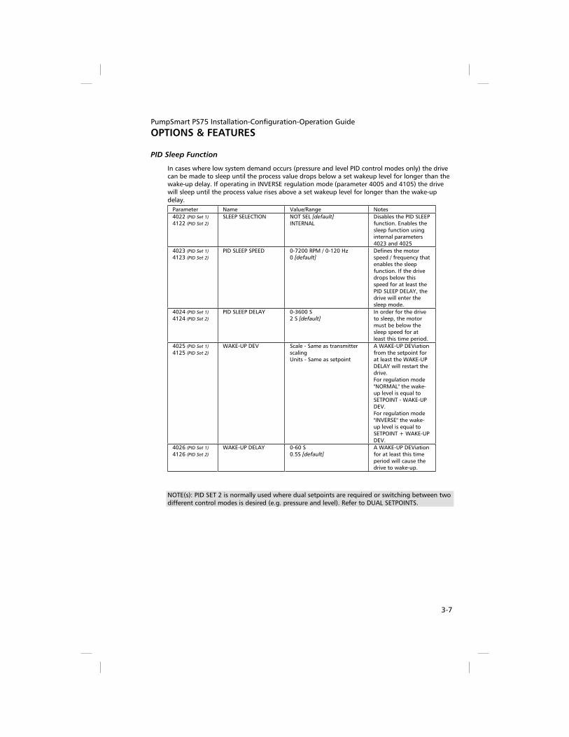
PID Sleep Function
In cases where low system demand occurs (pressure and level PID control modes only) the drive can be made to sleep until the process value drops below a set wakeup level for longer than the wake-up delay. If operating in INVERSE regulation mode (parameter 4005 and 4105) the drive will sleep until the process value rises above a set wakeup level for longer than the wake-up delay.
Parameter Name Value/Range Notes
4022 (PID Set 1)
4122 (PID Set 2)
SLEEP SELECTION NOT SEL [default]
INTERNAL Disables the PID SLEEP function. Enables the sleep function using internal parameters 4023 and 4025
4023 (PID Set 1)
4123 (PID Set 2)
PID SLEEP SPEED 0-7200 RPM / 0-120 Hz 0 [default]
Defines the motor speed / frequency that enables the sleep function. If the drive drops below this speed for at least the PID SLEEP DELAY, the drive will enter the sleep mode.
4024 (PID Set 1)
4124 (PID Set 2)
PID SLEEP DELAY 0-3600 S 2 S [default]
In order for the drive to sleep, the motor must be below the sleep speed for at least this time period.
4025 (PID Set 1)
4125 (PID Set 2)
WAKE-UP DEV Scale - Same as transmitter scalingUnits - Same as setpoint
A WAKE-UP DEViation from the setpoint for at least the WAKE-UP DELAY will restart the drive.For regulation mode "NORMAL" the wake-up level is equal to SETPOINT - WAKE-UP DEV. For regulation mode "INVERSE" the wake-up level is equal to SETPOINT + WAKE-UP DEV.
4026 (PID Set 1)
4126 (PID Set 2)
WAKE-UP DELAY 0-60 S 0.5S [default]
A WAKE-UP DEViation for at least this time period will cause the drive to wake-up.
NOTE(s): PID SET 2 is normally used where dual setpoints are required or switching between two different control modes is desired (e.g. pressure and level). Refer to DUAL SETPOINTS.

PumpSmart PS75 Installation-Configuration-Operation Guide
OPTIONS & FEATURES
3-8
Pump Protect
The Pump Protection Limit adds significant protection to the PumpSmart system. With the protection limit enabled, the PumpSmart system will be able to provide dry run (loss of or blocked suction) protection in pressure and flow control. It will also be able to provide run-out flow protection when in pressure control mode and min flow protection when in flow control.
The pump protection limit works by identifying conditions where the pump is unable to meet the protection limit while at parameter 2002 Maximum Speed. The protection limit setting should be just below your minimum acceptable setpoint value. Goulds recommends 2-3% below your setpoint for the initial setting.
The Pump Protection Limit is expressed in terms of % of setpoint.
Example – If you have a setpoint of 100 PSIG (or GPM, or FT, etc.) the recommended protection limit would be 97%. The Pump Protection warning/fault would occur if the pump was at maximum speed and the pressure fell below 97 PSIG.
NOTE(S) - A delay can be set so that PumpSmart waits to respond if the process variable falls below the protection limit. This will prevent the PumpSmart unit from shutting down prematurely due to momentary system upsets.
The final step in enabling the Pump Protection function is to select how you would prefer PumpSmart to respond if a pump Protect condition occurs. There are three choices:
1. ALARM & CONTROL (recommended) – In this response, PumpSmart will issue a warning and then either shutdown or reduce speed depending upon the desired setting. See Minimum Speed Options above.
2. ALARM only – In this response, PumpSmart will simply issue an alarm/warning, but continue to operate. The alarm only mode may result in damage to the pump if a pump protection condition occurs and no manual intervention is taken.
3. DISABLED (Default Setting) – In this response, there is no protection limit functionality. If a closed suction valve (or similar) condition exists there may be damage to the pump and there will be no warning to the user.
Parameter Name Value/Range Notes
1902 PUMP PROTECT DISABLED (Default) ALARM ALARM & CTRL
Actual process value is lower than protection limit (1903) for protection delay (1904) and “PumpSmart” is at (2002) max speed for the protection delay.
1903 PROTECTION LIMIT 0-100% 97% (Default)
The process condition, expressed as % of the Setpoint, that represents an upset condition when the pump is at maximum speed (2002)
1904 PROTECTION DELAY The delay period after the pump is operating at maximum speed AND at/below the Protection Limit before a fault is registered.
NOTE(S) - The PumpSmart Keypad will display an ALARM 2050 or FAULT 50 message “PUMP PROTECT” when the condition exists. The Pump Protection feature may also be configured to warn via DCS or audible or visual alarms via a digital relay output. See Fieldbus or Relay Outputs section for details.

PumpSmart PS75 Installation-Configuration-Operation Guide
OPTIONS & FEATURES
3-9
Regulation Mode
The PID regulation mode can either be NORMAL or INVERSE. The common selection is NORMAL, where the drive anticipates an increase in the process condition when pump speed is increased. If the regulation mode is set to INVERSE, the process condition is expected to increase with a decrease in pump speed.
EXAMPLE – If a PumpSmart unit is trying to control the level in a suction-side tank or sump, the regulation mode
would be set to INVERSE. As the level in the sump increased, PumpSmart would respond by increasing pump
speed to maintain a constant level.
Parameter Name Value/Range Notes
4005 PIDSET1 4105 PIDSET2
REGULATION MODE NORMAL [default] INVERSE
Inverse is normally used for control of suction side systems.
NOTE(S) - PID Set 2 is normally used where dual setpoints are required or switching between two different control modes is desired (e.g. pressure and flow). Refer to Dual Setpoints.

PumpSmart PS75 Installation-Configuration-Operation Guide
OPTIONS & FEATURES
3-10
Relay Outputs
PumpSmart has three relay outputs as standard that are configurable for different operating and fault conditions. For a complete listing refer to the parameter descriptions. Relays will revert to original states once alarms or faults are reset or cleared.
Relay Output Technical Information Switching capacity 6 A at 30 VDC or 1500 VA at 250 VAC
0.4 at 120 VDC
Maximum continuous current 2 A RMS (cos =1), 1 A RMS (cos = 0.4)
Refer to Technical Data Section “Control Connections” for complete specifications.
Parameter Name Value/Range NOTES
FAULT RUNNING READY
Default for RO3 Default for RO2 Default for RO1
FAULT (-1) Relay energizes when power is applied to drive. De-energizes on a fault.
FAULT Relay energizes when a fault is active.
ALARM Relay energizes when an alarm is active
FAULT (RST) Relay energizes when drive is faulted and is waiting to reset
FAULT/ALARM Relay energizes when a fault or alarm occurs
OVERCURRENT Relay energizes when an overcurrent alarm or fault occurs
OVERVOLTAGE Relay energizes when an overvoltage alarm or fault occurs
DRIVE TEMP Relay energizes when an overtemperature alarm or fault occurs
SENS ERR AI1 Relay energizes when AI1 signal is lost
SENS ERR AI2 Relay energizes when AI2 signal is lost
MOTOR TEMP Relay energizes when a motor overtemperature alarm or fault occurs
STALL Relay energizes when a stall alarm or fault occurs
UNDERLOAD Relay energizes when an underload alarm or fault occurs
PID SLEEP Relay energizes when sleep function is active.
PFC Relay is used to start/stop motor in PFC control
1401 1402 1403
RELAY R01 OUTPUT RELAY R02 OUTPUT RELAY R03 OUTPUT
NOT SEL
NOTE(S) - if the relay is set to detect a fault condition and the drive is in auto reset the relay will not change state until all resets have been exhausted and drive final faults. To activate a relay when the drive is in a fault condition and auto reset is active use the Fault (RST) setting.

PumpSmart PS75 Installation-Configuration-Operation Guide
OPTIONS & FEATURES
3-11
Restart Options
See MINIMUM SPEED OPTIONS
Secondary Protection
To provide protection from dry-running and operating against a closed discharge valve in process and speed control modes, the PumpSmart secondary protection feature may be used. In these cases, additional system condition inputs (e.g. level switch, pressure switch, flow switch, etc…) are used to alert PumpSmart of conditions that require protection of the pump.
Discharge Header
1Flow Switch
Speed Signal
SPEED CONTROL SECONDARY PROTECTION
In the above example, a unit is being controlled by an external speed signal. A flow switch is added to the pump installation and wired into the PumpSmart controller. This provides dry run and shutoff protection. A secondary protect fault will cause the drive to coast to a stop. The drive will display a message “Secondary Protect A FAULT 14 or B FAULT 15”. If PumpSmart is stopped due to a Secondary Protect fault, it will remain in a fault condition until the condition clears. Once the condition clears the fault can be either manually reset or auto reset. The AUTO RESET function is activated by enabling parameters 3101 ERROR RESET, 3103 RESET DELAY and 3108 ER SECONDARY PROTECT functions. However, once the set number of resets is exhausted the drive must be manually restarted. If the auto reset function is not enabled the drive must be restarted manually.
Parameter 3003 SECONDARY PROTECT A or 3004 SECONDARY PROTECT B must be wired and set to the location of the digital signal input. Any open digital input can be used.

PumpSmart PS75 Installation-Configuration-Operation Guide
OPTIONS & FEATURES
3-12
Parameter Name Value/Range Notes
3003 3004
SECONDARY PROTECT ASECONDARY PROTECT B
NOT SEL [default]
DI1 through DI6 DI1(INV) through DI6 (INV) Select any open digital input.
This is the location of the signal input for Secondary Protect A or B. Activation of DI1 through DI6 displays a Secondary Protect fault and the drive coasts to a stop. De-activating DI1(INV) through DI6(INV) displays a Secondary Protect fault and the drive coasts to a stop.
3101 ERROR RESET 1- 5 0 [default]
If the PumpSmart unit faults on Secondary Protection, this parameter will reset the fault up to the selected number of times before completely shutting off the drive.
3103 RESET DELAY 0 -120 seconds 60 [default]
The automatic reset of protection faults can be delayed.
3108 ER SECONDARY PROTECT
Disable [default] Enable
Enables the auto reset of a secondary protect condition if 3101 Error Reset is set >0 .

PumpSmart PS75 Installation-Configuration-Operation Guide
OPTIONS & FEATURES
3-13
Sensor or Keypad Failure
In the event of a process transmitter failure or a keypad failure, PumpSmart has been configured to run the pump at an average speed of the 10 seconds preceding the instrument failure. This functionality can be disabled (sensor failure only), or configured to result in a drive fault.
A sensor failure is determined when:
- A 2-10 VDC Voltage Signal is <1.5 VDC
- A 4 – 20 mA Current Signal is <3 mA
- Keypad Communication with keypad is interrupted
Available failure response settings:
- LAST SPEED - PumpSmart will average the pump speed of the 10 seconds prior to the instrument failing and run at the calculated speed and issue a warning message.
- DISABLED - No protection is provided and PumpSmart will attempt to run as close to the failed sensor signal as possible. Warning if the transmitter fails “low” the pump may
accelerate to Maximum Speed (2002).
- FAULT - Upon sensing an instrument failure, PumpSmart will trip (stop) the drive and issue a fault message
Parameter Name Value/Range Notes
3001 SENSOR FAILURE NOT SEL FAULT LAST SPEED[default]
Applies to process transmitter inputs and analog setpoint inputs. Failure messages indicate which transmitter channel has failed: Sensor ERR AI1 – transmitter on AI1 has failed.Sensor ERR AI2 - transmitter on AI2 has failed.
3002 KEYPAD FAILURE FAULT LAST SPEED[default]
Fault message - "KEYPAD FAIL"
!!!WARNING!!
Do not select Last Speed for parameter 3002 Keypad Failure unless the drive is in REM mode and can be stopped by an external switch, E-stop or fieldbus command
NOTE(S) - a sensor failure can be automatically reset by setting parameter 3107 ER SENSOR FAILURE to “Enable” and parameter 3101 ERROR RESET to the desired number of resets.

PumpSmart PS75 Installation-Configuration-Operation Guide
OPTIONS & FEATURES
3-14
Setpoints, Dual
PumpSmart can toggle between two fixed setpoints or one fixed setpoint and one variable setpoint. The toggling between setpoints may be accomplished using a digital switch or through Fieldbus control. The parameter setup differs between Speed Control (Standard) and Process PID Control.
Speed Control (Standard)
Example - An application requires a fixed speed of 3000 RPM for one setpoint and 1800 RPM via an analog input for a second setpoint. PumpSmart configuration would be:
Parameter Name Value/Range
1103 SPD REF 1 SEL AI1
1104 SPD REF 1 MIN 0 RPM
1105 SPD REF 1 MAX 3600 RPM
1201 CONST SPD SEL DI3
1202 CONST SPD 1 3000 RPM
If it was desired to have 3000 RPM as SETPOINT 1 and 1800 RPM as SETPOINT 2, then set parameter 1201 CONST SPD SEL to DI3(INV). This will select the constant speed setpoint (e.g. 3000 RPM) when DI3 is open/low and the AI1 signal (e.g. 1800 RPM analog input) when DI3 is closed/high.
Process PID
Example - An application requires 150 GPM for wash-down in one case and 100 GPM in another case. The flowmeter is a magmeter have a 4-20 mA signal scaled for 0-200 GPM. PumpSmart configuration would be:
PID SET 1
SETPOINT 1
PID SET 2
SETPOINT 2 Name Value/Range
4001 4101 GAIN 0.7
4002 4102 INTEGRATION TIME 1.0
4006 4106 UNITS Gpm
4008 4108 0% PV SCALE 0
4009 4109 100% PV SCALE 200
4010 4110 SETPOINT SEL KEYPAD [default]
4016 4116 PV ACT 1 INPUT AI2 [default]
4027 -- PID SET1/SET2 SEL DI3
The setpoint is shown as a % in the upper right of the keypad display. In the example above a setting of 75% represents a setpoint of 150 GPM. To set a value for SETPOINT 2
(100 Gpm) toggle (close/high) the switch wired to DI3 and enter 50% via the keypad pushbutton.

PumpSmart PS75 Installation-Configuration-Operation Guide
OPTIONS & FEATURES
3-15
Setpoints, Variable
Variable setpoints are possible with the PumpSmart system using a 2-10 VDC or 4-20 mA input signal. The signal affects only the setpoint. Motor speed continues to be varied by the primary transducer reading the demand change. A example application is sending a setpoint from a control room to the PumpSmart unit using a 2-10VDC or 4-20 mA signal.
2 VDC
10 VDC20 mA
4 mA
An
alo
g In
pu
t 1
[A
I1]
% Setpoint (AI2)
0 % 100%
Straight Relatio
nship
50%
12 mA
75%
16 mA
The effect is a straight relationship with the maximum setpoint value corresponds to the maximum signal [i.e. 20 mA or 10 VDC] while the minimum setpoint value corresponds to the minimum signal [4mA or 2 VDC].
Speed Control (Standard)
Parameter Name Value/Range NOTES
1103 SPEED REF 1 SEL KEYPAD [default]
AI1AI2COMM
Change to AI1 or AI2 if using an analog signal. Select COMM if a variable setpoint is being introduced through a DCS system
1104 SPEED REF 1 MIN Range: 0-30,000 0 [default]
Enter value of the speed that corresponds to a 4mA or 2 VDC signal as read from AI1 or AI2
1105 SPED REF 1 MAX Range: 0-30,000 PAR 9908 Setting [default]
Enter value the speed that corresponds to a 20mA or 10 VDC signal as read from AI1 or AI2

PumpSmart PS75 Installation-Configuration-Operation Guide
OPTIONS & FEATURES
3-16
Process PID
Parameter Name Value/Range NOTES
4010 SETPOINT SEL KEYPAD [default]
AI1COMM
Change to AI1 if using an analog signal. Select COMM if a variable setpoint is being introduced through a DCS system
4009 100% PV SCALE Range: 0-3275 100 [default]
Enter the value from the process transmitter that corresponds to a 20mA or 10 VDC signal as read from AI-2
4008 0% PV SCALE Range: 0-3275 0 [default]
Enter value from the process transmitter that corresponds to a 4mA or 2 VDC signal as read from AI2
4006 UNIT % [default]
FT PSI GPM LB/m LB/h (See parameter list for
complete listing)
Selects the units to display on the keypad for the primary process transmitter.
Stall Function (Locked Rotor Protection)
The stall function selects how the motor will react in a locked rotor condition. A locked rotor condition can occur if operating the pump in reverse rotation (threaded impeller spins off), binding of parts (due to misalignment) or foreign debris.
NOTE(S) - The Stall function can be found in Group 30 Fault Functions
Parameter Name Value/Range Notes
3010 STALL FUNCTION Warning FaultNOT SEL [default]
PumpSmart reaction when a locked rotor condition occurs for the stall time
3011 STALL FREQUENCY 0.5 – 50 HZ 20 HZ [default]
Default setting recommended
3012 STALL TIME 10 – 400 sec 10 sec [default]
Recommended setting is 10 sec
NOTE(s): The stall function activates when operating at, or above, 95% of the torque value set in parameter 2017 MAX TORQUE 1 (default 300%) and if the actual frequency is less than the stall frequency for at least the STALL TIME.
Stop Function
Parameter 2102 selects how the motor will stop when the stop button is pushed. If a fault occurs the PumpSmart will coast stop.
Parameter Name Value/Range Notes
2102 STOP FUNCTION RAMP STOP COAST STOP[default]
Selects how the motor will stop. Ramp Stop uses the parameter 2203 deceleration ramp. Coast Stop cuts the motor power as the stop method.

PumpSmart PS75 Installation-Configuration-Operation Guide
OPTIONS & FEATURES
3-17
Torque Based Pump Protection [TPP]1
The PumpSmart Torque Based Pump Protection logic protects the pump from operating in underload conditions [e.g. dry-run, minimum flow] or in overload conditions [e.g. run-out] without the need for external sensors to monitor the system. The PumpSmart TPP monitors the torque of the pump and compares it to underload and overload setpoints. A key feature of the PumpSmart TPP is its ability to compensate for changes in speed and mechanical losses [e.g. mechanical seal drag].
There are three steps to manually enabling PumpSmart TPP:
1. Determining the Reference Operating Point
2. Establishing underload and overload setpoints
3. Entering mechanical load offsets
For automatic set-up of PumpSmart TPP, refer to the Pump Protection Assistant
REFERENCE OPERATING POINT
The reference operating point serves as the reference torque from which the underload and overload conditions are compared to. This point is normally the Best Efficiency Point [BEP] of the pump at its maximum speed. The PumpSmart logic will calculate the reference operating point based upon the BEP power and speed.
The following chart depicts a typical ANSI pump performance and power curve:
6570
7578
78
75
50 hp
40 hp
30 hp
20 hp
13 in
12 in
11 in
10 in
9 in
200
180
160
140
120
100
80
60
40
20
00 200 400 600 800 1000 1200 1400 1600 GPM
Ft
ANSI 4x6-13RPM: 1780
0
10
20
30
40
50
60
0 200 400 600 800 1000 1200 1400 1600 GPM
hp
Minimum FlowExample: 34 hp
BEP PowerExample: 56 hp
Closed DischargeExample: 26 hp
MinimumFlow
Runout PowerExample: 62 hp
1 Patent Pending

PumpSmart PS75 Installation-Configuration-Operation Guide
OPTIONS & FEATURES
3-18
NOTE – Application of the Torque Pump protect functionality is limited to pumps having power curves that are constantly rising from a closed valve operating condition. These pumps typically have specific speeds of 2000 or under.
The BEP may easily be determined two ways; interpolation of the performance curves or calculation using the basic equation of:
PBEP
=Q
GPM x H
FT
3960 x Efficiencyx S.G.
If the power is interpolated from the performance curve, specific gravity (SG) and viscosity must be accounted for.
NOTE - PumpSmart TPP assumes that specific gravity and viscosity remain constant during operation. It is recommended that these fluctuations do not exceed + - 5%. The power at BEP is only useful if the speed is also known. The speed is used for factoring the reference point and setpoints according to the Affinity Laws.
Parameter Name Value/Range Note
1905 BEP POWER 0-9999 This is the power at the Best Efficiency Point of the pump (at installed impeller diameter) with specific gravity and viscosity effects considered. The default of this entry is 90% of the motor power, as defined by 9909 MOTOR NOM POWER
1907 BEP SPEED 0-9999 This is the speed that the BEP POWER is expressed. The default value for this entry is 9908 MOTOR NOM SPEED. This value should be based upon your performance curve calculations.
ESTABLISHING LOAD SETPOINTS
There are three general conditions that the PumpSmart TPP logic can protect against; Operation below minimum flow, dry running, and run-out conditions. Conditions such as cavitation will also be identified, however the response of the PumpSmart system to these conditions will be based upon how severe their impact is on the pump loading.
The first underload setpoint to set is Minimum Flow. The MINIMUM FLOW TORQUE is expressed as a percentage (%) of the BEP Power. The load at minimum flow may be determined prior to operation by graphical interpolation of the pump performance curve. PumpSmart parameter 1915 CALC TEST TRQ% may also be used when the pump is operating. This parameter will display the current torque, as a percentage of the speed corrected BEP torque, and may be used directly to set 1909 MIN FLOW TORQUE.
Example: An ANSI 4x6-13 operating on water has a BEP POWER of 56 HP when at 1780 RPM. The minimum flow power is estimated at 34 HP at 1780 RPM. The MIN FLOW TORQUE setpoint would be 34HP/56 HP, or 61%. Enter this value in parameter 1909 MIN FLOW TRQ. This value
could be verified by checking parameter 1915 CALC TEST TRQ% when running the pump at 1780 RPM and throttling it to minimum flow.

PumpSmart PS75 Installation-Configuration-Operation Guide
OPTIONS & FEATURES
3-19
The second underload setpoint identifies Dry Running conditions. A dry run condition could be operating with no fluid in the suction, or in a severely cavitating state. Dry run conditions can normally be estimated as 10% below the power at shut-off (zero flow). This value can be estimated by interpolating the pump performance curve.
!!! WARNING !!
Do not attempt to determine the dry running setpoint by operating the pump in dry-run or severe cavitation states. Permanent damage or failure
to the pump may occur.
Example: An ANSI 4x6-13 operating on water has a BEP POWER of 56 HP when at 1780 RPM. The power at shut-off is estimated at 26 HP when at 1780 RPM. The DRY RUN TORQUE setpoint would be (26HP/56 HP) x 0.9, or 42%. This value is entered in parameter 1911 DRY RUN TRQ
The last setpoint to configure is the run-out load. In this condition, pump power is increasing as the pump runs out in flow. PumpSmart can identify this condition and slow the pump down to an acceptable loading condition. This condition may be determined through performance curve interpolation, calculation, or through actual operation at the run-out condition. The RUNOUT TORQUE setpoint is entered into parameter 1913 RUNOUT TRQ.
Parameter Name Value/Range Note
1908 MIN FLOW CTRL DISABLED [default]
WARNING ALARM & CTRL
Selects the response of the drive to a minimum flow condition. Warning will issue a keypad warning and effect relay change (if configured). Alarm & Control will slow the pump to minimum speed or fault (depending how configured) and attempt resets according to parameter 3101 ERROR RESET
1909 MIN FLOW TRQ 0-200% 0 %[default]
The load, as percentage of BEP loads, when at a minimum flow condition.
1910 DRY RUN CTL DISABLED [default]
WARNING FAULT
Selects the response of the drive to a dry-running condition. Warning will issue a keypad warning and effect relay change (if configured). Fault will shut the pump down until it is manually reset.
1911 DRY RUN TRQ 0-200% 0 %[default]
The load, as percentage of BEP load, when at a dry run condition.

PumpSmart PS75 Installation-Configuration-Operation Guide
OPTIONS & FEATURES
3-20
Parameter Name Value/Range Note
1912 RUNOUT CTL DISABLED [default]
WARNING ALARM & CTRL
Selects the response of the drive to a run-out condition. Warning will issue a keypad warning and effect relay change (if configured). Alarm & control will decrease pump speed so as not to exceed the runout torque limit. If the unit reaches Minimum Speed it will attempt resets according to parameter 3101 ERROR RESET.
1913 RUNOUT TRQ 0-200% 200 % [default]
The load, as percentage of BEP load, when at a run-out condition.
1914 RUNOUT RAMP 5-100 seconds 20 seconds [default]
The deceleration ramp rate when decreasing speed due to a run-out condition.
1915 CALC TEST TRQ % The current load, as a percentage of the speed corrected BEP load.
MECHANICAL POWER OFFSETS
The hydraulic power in a centrifugal pump at varying speeds can normally be determined using the pump Affinity Laws. At reduced speeds, this estimation may be affected by mechanical losses. The mechanical offset parameter allows for such losses to be accounted for.
The mechanical power offset is expressed as hp or kW, depending upon the drive model number and units of parameter 9909 Motor Nom Power. US Drive models are expressed in hp; IEC models are expressed in kW. Power Offset is applied when the pump is being operated at speeds below 1/3 of its full speed.
Parameter Name Value/Range Note
1906 PWR OFFSET -20.0 to 20.0 The power offset is used to correct the load setpoints when at low speeds. The units are the same as expressed in parameter 9909 MOTOR NOM POWER (HP or kW).

PumpSmart PS75 Installation-Configuration-Operation Guide
OPTIONS & FEATURES
3-21
Mechanical seal losses are the most common form of offset. The following table may be used as a starting point:
Nominal Mechanical Seal Size per Pump Shaft Diameter (in)
Single Inside Seal Losses Hp (kW) RPM
1.375 1.75 2.125 2.50 2.75 3.00 3.75
3560 0.38
(0.28) 0.44
(0.33) 0.52
(0.39) 0.62
(0.46) 0.70
(0.52) - -
2900 0.31
(0.23) 0.36
(0.27) 0.43
(0.32) 0.51
(0.38) 0.57
(0.43) - -
1780 0.19
(0.14) 0.22
(0.16) 0.26
(0.19) 0.31
(0.23) 0.35
(0.26) 0.39
(0.29) 0.54
(0.40)
1470 0.16
(0.12) 0.18
(0.13) 0.22
(0.16) 0.26
(0.19) 0.29
(0.22) 0.32
(0.24) 0.44
(0.33)
1180 - 0.15
(0.11) 0.17
(0.13) 0.21
(0.16) 0.23
(0.17) 0.26
(0.19) 0.35
(0.26)
960 - 0.12
(0.09) 0.14
(0.10) 0.17
(0.13) 0.19
(0.14) 0.21
(0.16) 0.29
(0.22)
885-
- - - - 0.19
(0.14) 0.27
(0.20)
740-
- - - -
0.16 (0.12)
0.22 (0.16)
Double Inside Seal Losses Hp (kW) RPM
1.375 1.75 2.125 2.50 2.75 3.00 3.75
3560 0.68 (0.51)
0.8 (0.60)
0.94 (0.70)
1.12 (0.84)
1.25 (0.93)
- -
2900 0.56 (0.42)
0.65 (0.48)
0.77 (0.57)
0.91 (0.68)
1.02 (0.76)
- -
1780 0.34 (0.25)
0.40 (0.30)
0.47 (0.35)
0.56 (0.42)
0.63 (0.47)
0.70 (0.52)
0.96 (0.72)
1470 0.28 (0.21)
0.33 (0.25)
0.39 (0.29)
0.46 (0.34)
0.52 (0.39)
0.58 (0.43)
0.80 (0.60)
1180 -
0.26 (0.19)
0.31 (0.23)
0.37 (0.28)
0.42 (0.31)
0.46 (0.34)
0.64 (0.48)
960-
0.22 (0.16)
(0.25 (0.19)
0.31 (0.23)
0.34 (0.25)
0.38 (0.28)
0.52 (0.39)
885-
- - - -
0.35 (0.26)
0.48 (0.36)
740-
- - - -
0.29 (0.22)
0.40 (0.30)
For between bearing pumps, double the above values.
The final Power Offset value can be determined by viewing the value of parameter 1915 CALC TEST TRQ % while the pump is operating. The recommended procedure is as follows:
1. Check the value of 1915 CALC TEST TRQ % while operating at the normal process setpoint.
2. Next reduce the pump speed to 2001 MINIMUM SPEED. To do this in single pump control lower the setpoint until the minimum speed is reached. Check the value of 1915 CALC TEST TRQ % again. Important: do not change any valve or system settings during this process.
3. If the value of 1915 CALC TEST TRQ % is greater than in Step 1 increase the power offset value until the Calc Test Trq % has approximately the same value as in Step 1.
4. Return PumpSmart to normal process control by re-setting the setpoint.
Note: for some large hp motors the value of 1915 CALC TEST TRQ % as viewed in step 3 may be less than in step1. In this case a small negative value of power offset should be used.
Helpful Hint: to avoid nuisance trips during system transients set a protection delay (parameter 1904).

PumpSmart PS75 Installation-Configuration-Operation Guide
OPTIONS & FEATURES
3-22
Tuning (Process Control)
If the pump appears to oscillate in speed (i.e. hunting), cannot maintain a uniform setpoint, has a constant setpoint offset, or shuts off too quickly or too slowly it may need to have the integral time or proportional gain settings tuned to the system.
PumpSmart uses default values for normal and inverse regulation mode. In many pressure or level control applications, these settings will not require adjustment. The most common exceptions are complex systems, process instruments with slow response times, large full-scale value compared to setpoint or level control applications where variables such as tank size have a significant effect on tuning response. Typical values for flow, pressure, level, and temperature applications are shown on page 3-23.
When the PumpSmart system is adjusting speed to meet the setpoint, it does so using a Proportional Gain and Integral Time (PI) setting. The proportional gain setting adds corrective action that is proportional to the difference between the setpoint and the process condition. This difference is commonly referred to as error. A low gain setting will yield a small corrective action that may stabilize at a position that is offset from the setpoint. Conversely, if the gain setting is too high, speed oscillations may occur.
The integral time setting makes corrective actions to compensate for the offset created by the proportional control. The corrective action of the integral function accounts for the error present over a period of time (Integral Time). The smaller the Integral time, the faster speed adjustments are made, at the risk of speed oscillations occurring. If the Integral time is set too long, prolonged offsets are likely.
It is important to note that the final values for the Proportional gain and Integral time should be determined not only for system changes but also for startup conditions. For example, a system tuned for system operating changes may be out of tune during startup conditions.
NOTE - Air in the system may cause a condition that looks like oscillation or hunting. Be sure all air is purged from the system before attempting tuning.
ACCEL TIME
ACCELeration TIME is the rate at which motor speed is increased when a control correction is required. ACCEL TIME is expressed as the time, in seconds, it would take to reach maximum speed (parameter 2002) from zero speed. The drive response can be made slower by increasing the ACCEL TIME
Parameter Name Value/Range Notes
2202 ACCEL TIME 1 0-1800 Seconds 5 [default]
DECEL TIME
Deceleration time is the rate at which motor speed is decreased when a control correction is required or upon shutting down. DECEL TIME is expressed as the time, in seconds, it would take to reach zero speed from maximum speed (parameter 2002). As with ACCEL TIME, drive response may be slowed using this parameter.
Parameter Name Value/Range Notes
2203 DECEL TIME 1 0-1800 Seconds 5 [default]
PROPORTIONAL GAIN
The PROPORTIONAL GAIN setting adds corrective action that is proportional to the error. A low gain setting will yield a small corrective action that may stabilize at a position that is offset from the setpoint. A high gain setting may result in speed oscillations.
Parameter Name Value/Range Notes
4001 / 4101 GAIN 0.1-100 1 [default NORMAL]
25 [default INVERSE]

PumpSmart PS75 Installation-Configuration-Operation Guide
OPTIONS & FEATURES
3-23
INTEGRAL TIME
The integral time setting compensates for offset between the process variable and the setpoint. The integral time produces a rate of change in output speed that is proportional to the deviation in process variable from the setpoint. The smaller the integral time the faster the speed adjustments are made. If the integral time is set too short speed oscillations may occur, if set too long a prolonged time period is likely prior to achieving the setpoint value.
Parameter Name Value/Range Notes
4002 / 4102 INTEGRATION TIME 0-3600 Sec 0.7s [default NORMAL]
150s [default INVERSE]
A setting of 0 seconds turns off the integration function and makes the PI controller behave as a Proportional-only controller.
Typical starting values for parameters 4001/4101 and 4002/4102 are shown below. The derivative time (parameter 4003/4103) is initially defaulted to zero for all operating modes. The ACCEL TIME 1 (2202) and DECEL TIME 1 (2203) are default set at 5 seconds.
Operating Mode
ACCEL TIME 1 Seconds
DECEL TIME 1 Seconds
GAIN INTEGRATION TIME
Flow 5 5 0.7 1.0
Pressure 5 5 1.0 0.7
Level 5 5 25 150
Temperature 5 5 25 150
NOTE(s) - There are two PID groups; Group 40 is for PROCESS PID SET 1, Group 41 is for PROCESS PID SET 2. Setting group 41 parameters are required if toggling between two setpoints while in PID control or if dual control modes are selected.
RECOMMENDED GUIDELINES
Although there is no tuning procedure that will give optimum results for every system, there are certain guidelines that will facilitate the tuning process in the event the default settings require adjustment. The following figures show both normally tuned systems and improperly tuned systems. The first two figures “Normally Tuned” and “Tuned” show examples of properly tuned systems. Note the second figure, “Tuned” has a better dynamic response then the first system, but at the expense of a small overshoot in the setpoint. The last two figures show examples of poorly tuned systems that result in an unstable undesirable response.
Normally the default settings for ACCEL TIME 1 and DECEL TIME 1 do not require adjustment unless the drive response during ramp up or ramp down to the setpoint is unsatisfactory for the particular process.
If the default settings result in an unsatisfactory drive response the following rules of thumb can be applied:
- If rapid oscillations occur about the setpoint try increasing the value of the integral time (parameter 4002/4102) first. If the oscillations still continue or the time to drop to the setpoint is too long the proportional gain (parameter 4001/4101) should also be lowered.
- If the amount of overshoot is unacceptable increase the integral time and lower the proportional gain.
- If there is a low offset in the setpoint the proportional gain should be increased.
- If there is a lengthy time period before achieving the final setpoint the integral time should be decreased.
- In level control applications if speed oscillations occur increase the integral time.
- Once the tuning is fairly close several iterations between the values of proportional gain and integral time may be required to obtain optimum results.
- It is important to note that the final values for the proportional gain and integral time should be determined not only for system changes but also for startup conditions.

PumpSmart PS75 Installation-Configuration-Operation Guide
OPTIONS & FEATURES
3-24
Setpoint
Pro
cess
Vari
ab
le
Time
Normally tuned system: This system has appropriate gain and integration times resulting in a smooth transition towards the setpoint.
Setpoint
Pro
cess
Vari
ab
le
Time
Tuned system: This system tuning is also acceptable. There is a slight overshoot to the setpoint, however the response rate is better than the previous “Normally Tuned” system.

PumpSmart PS75 Installation-Configuration-Operation Guide
OPTIONS & FEATURES
3-25
Setpoint
Pro
cess
Vari
ab
le
Time
Over-Compensated system: In this case, the drive is over-compensating to the error in the setpoint resulting in an oscillation. The proportional gain is too high and the integration time is too short.
Setpoint
Pro
cess
Vari
ab
le
Time
Under-Compensated system: In this case, the drive is under-compensating to the error in the setpoint. The integration time in this case is too long.

PumpSmart PS75 Installation-Configuration-Operation Guide
OPTIONS & FEATURES
3-26
DERIVATIVE RESPONSE
NOTE(S) - The Derivative function can be found in the Advanced Parameter section accessible in the viewable parameters assistant.
Derivative action completes the PID controller capability and is useful in systems where there is a sudden change in process variable. Derivative action will respond to a sudden change in process variable with a response similar to a high proportional gain but after this initial response behaves similar to a PI controller. Derivative action will respond to a sudden change in process variable faster then by just using PI control. In most pump applications PI control will be sufficient. However, PID control may be very useful in some level and temperature control applications.
Parameter Name Value/Range Notes
4003 4103
DERIVATIVE TIME 0-10 sec 0 [default]
Defines the derivation time of the PID controller.
4004 4104
PID DERIV FILTER 0-10 sec 1 [default]
Defines the time constant of the filter used to smooth the derivative component of the process PID controller
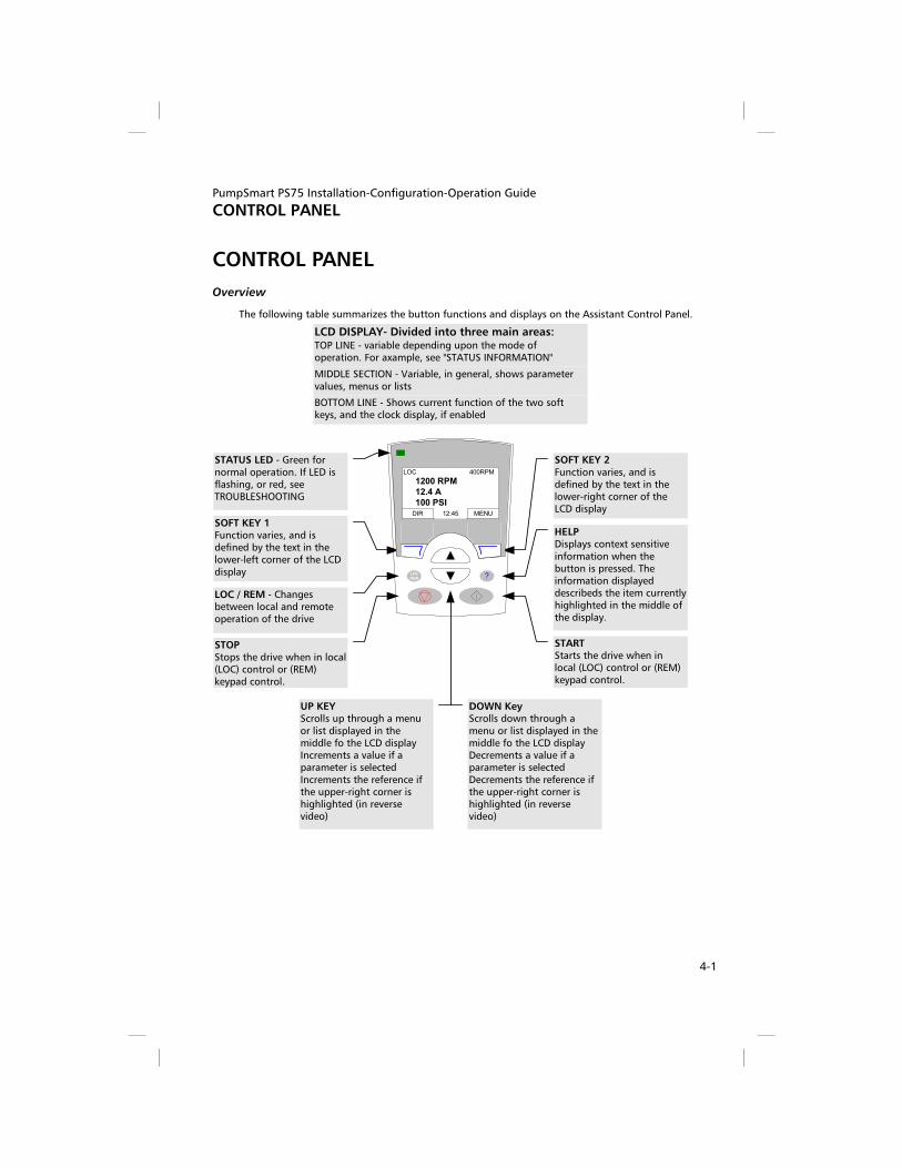
PumpSmart PS75 Installation-Configuration-Operation Guide
CONTROL PANEL
4-1
CONTROL PANEL
Overview
The following table summarizes the button functions and displays on the Assistant Control Panel.
STATUS LED - Green fornormal operation. If LED isflashing, or red, seeTROUBLESHOOTING
SOFT KEY 1Function varies, and isdefined by the text in thelower-left corner of the LCDdisplay
SOFT KEY 2Function varies, and isdefined by the text in thelower-right corner of theLCD display
LOC / REM - Changesbetween local and remoteoperation of the drive
STOPStops the drive when in local(LOC) control or (REM)keypad control.
STARTStarts the drive when inlocal (LOC) control or (REM)keypad control.
HELPDisplays context sensitiveinformation when thebutton is pressed. Theinformation displayeddescribeds the item currentlyhighlighted in the middle ofthe display.
UP KEYScrolls up through a menuor list displayed in themiddle fo the LCD displayIncrements a value if aparameter is selectedIncrements the reference ifthe upper-right corner ishighlighted (in reversevideo)
DOWN KeyScrolls down through amenu or list displayed in themiddle fo the LCD displayDecrements a value if aparameter is selectedDecrements the reference ifthe upper-right corner ishighlighted (in reversevideo)
LCD DISPLAY- Divided into three main areas:
BOTTOM LINE - Shows current function of the two softkeys, and the clock display, if enabled
TOP LINE - variable depending upon the mode ofoperation. For axample, see "STATUS INFORMATION"
MIDDLE SECTION - Variable, in general, shows parametervalues, menus or lists
LOC
REM ?
LOC 400RPM
1200 RPM
12.4 A
100 PSIDIR MENU12:45

PumpSmart PS75 Installation-Configuration-Operation Guide
CONTROL PANEL
4-2
GENERAL DISPLAY FEATURES
Soft Key Functions
The soft key functions are defined by text displayed just above each key.
Display Contrast
To adjust display contrast, simultaneously press the MENU key and UP or DOWN, as appropriate.
OUTPUT MODE
Use the Output mode to read information on the drive’s status and to operate the drive. To reach the Output mode, press EXIT until the LCD display shows status information as described below.
Status Information
TOP. The top line of the LCD display shows the basic status information of the drive.
- LOC – indicates that the drive control is local, that is, from the control panel.
- REM – indicates that the drive control is remote, such as the basic I/O (X1) or fieldbus.
- indicates the drive and motor rotation status as follows:
Control Panel Display Significance
Rotating arrow (clockwise or counter clockwise) – Drive is running and at setpoint
– Shaft direction is forward or reverse
Rotating dotted blinking arrow Drive is running but not at setpoint.
Stationary dotted arrow Start command is present, but motor is not running. E.g. start enable is missing.
- Upper right – shows the active reference.
MIDDLE. Using parameter Group 34, the middle of the LCD display can be configured
to display:
- Up to three parameter values.
– By default, the display shows three parameters. The particular parameters depend on the assistant selected. For example, PROCESS CONTROL assistant displays PID 1 Setpoint (0128) Speed (0102) and PID 1 FDBK (0130)
– Use parameters 3401, 3408, and 3415 to select the parameters (from Group 01) to display. Entering “parameter” 0100 results in no parameter displayed. For example, if 3401 = 0100 and 3415 = 0100, then only the parameter specified by 3408 appears in the Control Panel display.
– You can also scale each parameter in the display, for example, to convert the motor speed to a display of conveyor speed. Parameters 3402…3405 scale the parameter specified by 3401, parameters 3409…3412 scale the parameter specified by 3408, etc…
– A bar graph rather than any of the parameter values.
– – Enable bar graph displays using parameters 3404, 3411 and 3418.
LOC 15Hz
15.0 HZ
3.7 AFout
DIR MENU12:45
29%
LOC 15Hz
15.0 HZ
3.7 A
17.3%DIR MENU12:45

PumpSmart PS75 Installation-Configuration-Operation Guide
CONTROL PANEL
4-3
BOTTOM. The bottom of the LCD display shows:
– Lower corners – show the functions currently assigned to the two soft keys.
– Lower middle – displays the current time (if configured to show the time).
Operating the Drive
LOC/REM – The very first time the drive is powered up, it is in the remote control (REM) mode, and is controlled from the Control Terminal Block X1.
To switch to local control (LOC) and control the drive using the control panel, press and hold the LOC/REM button until first, LOCAL CONTROL, or later, LOCAL, KEEP RUN, is displayed:
– • Release the button while LOCAL CONTROL is displayed to set the panel reference to the current external reference. The drive stops.
– • Release the button when LOCAL, KEEP RUN is displayed, to copy the current run/stop status and the reference from the user I/O.
To switch back to remote control (REM) press and hold the LOC/REM button until REMOTE CONTROL is displayed.
Start/Stop – To start and stop the drive press the START and STOP buttons.
Shaft direction – To change the shaft direction press DIR (parameter 1003 must be set to 3 (REQUEST)).
Reference – To modify the reference (only possible if the display in the upper right corner is highlighted) press the UP or DOWN buttons (the reference changes immediately).
The reference can be modified when in local control (LOC), and can be parameterized (using Group 11: Reference Select) to also allow modification when in remote control (REM).
NOTE(S): The default arrangement for the PS75 is to start/stop the drive via the keypad in REM mode for both the startup and process control assistants.
OTHER MODES
Besides the Output mode, the Assistant Control Panel has:
– Other operating modes that are available through the main menu.
– A fault mode that is triggered by faults. The fault mode includes a diagnostic assistant mode.
– An alarm mode that is triggered by drive alarms.
Access to Main Menu and the Other Modes
To reach the main menu:
1. Press EXIT, as necessary, to step back through the menus or lists associated with a particular mode. Continue until you are back to the Output mode.
2. Press MENU from the Output mode. (At this point, the middle of the display is a listing of the other modes, and the top-right text says “Main menu”)
3. Press UP/DOWN to scroll to the desired mode.
4. Press ENTER to enter the mode that is highlighted.
The following sections describe each of the other modes.
PARAMETERS
CHANGED PAR
ASSISTANTS
LOC MAIN MENU ---------1
EXIT ENTER

PumpSmart PS75 Installation-Configuration-Operation Guide
CONTROL PANEL
4-4
PARAMETERS MODE
Use the Parameters mode to view and edit parameter values:
1. Select PARAMETERS in the Main Menu.
2. Press UP/DOWN to highlight the appropriate parameter group, then press SEL.
3. Press UP/DOWN to highlight the appropriate parameter in a group.
NOTE(S) The current parameter value appears below the highlighted parameter.
4. Press EDIT.
5. Press UP/DOWN to step to the desired parameter value.
NOTE(S) To view the parameter default value: In the set mode, press UP/DOWN simultaneously.
6. Press SAVE to store the modified value or press CANCEL to leave the set mode. Any modifications not saved are cancelled.
7. Press EXIT to return to the listing of parameter groups, and again to return to the main menu.
START-UP ASSISTANT MODE
When the drive is first powered up, the Start-up Assistant guides you through the setup of a few basic parameters. For example, at the first start, the drive automatically suggests entering the first task, Language Select.
The Start-up Assistant is divided into assistants:
1. Start-up
2. Process Control
3. Tune
4. Pump Protection
When first setting up your PumpSmart PS75, begin with the START-UP assistant. This will configure the drive for basic operation, including rotation checks. Once you have completed this, you may move on to PROCESS CONTROL or PUMP PROTECTION. You are not required to use the assistant, you may use instead, the parameter mode to set the drive parameters. For more information, refer to the section titled CONFIGURATION ASSISTANTS.
PARAMETERS
CHANGED PAR
ASSISTANTS
LOC MAIN MENU ---------1
EXIT ENTER
01 OPERATING DATA99 START-UP DATA
04 FAULT HISTORY10 START / STOP DIR11 REFERENCE SELECT
LOC MAIN MENU ---------1
EXIT ENTER
1102 EXT1/ EXT 2 SEL
EXT 1
1101 KEYPAD REF SEL
1103 REF 1 SELECT1104 REF1 MIN
LOC MAIN MENU ---------1
EXIT ENTER
LOC PAR EDIT -------------
1102 EXT1/EXT2 SEL
EXT1
CANCEL SAVE

PumpSmart PS75 Installation-Configuration-Operation Guide
CONTROL PANEL
4-5
CHANGED PARAMETERS MODE
Use the Changed Parameters mode to view (and edit) a listing of all parameters that have been changed from macro default values.
Procedure:
1. Select CHANGED PAR in the Main Menu. The display lists all changed parameters.
2. Press ENTER.
3. Press UP/DOWN to select a changed parameter. As each parameter is highlighted, the parameter value appears.
4. Press EDIT to edit the parameter value.
5. Press UP/DOWN to select a new value / edit the parameter value. (Pressing both keys at the same time sets a parameter to its default value.)
6. Press SAVE to save the new parameter value. (If the new value is the default value, the parameter will no longer appear on the Changed Parameters listing.)
FAULT LOGGER MODE
Use the Fault Logger Mode to see drive fault history, fault state details and help for the faults.
1. Select FAULT LOGGER in the Main Menu.
2. Press ENTER to see the latest faults (up to 10 faults, maximum).
3. Press DETAIL to see details for the selected fault.
– Details are available for the three latest faults.
4. Press DIAG to see the help description for the fault. See "Diagnostics" section.
NOTE(S) If a power off occurs, only the three latest faults will remain (with details only for the most recent fault).
CLOCK SET MODE
Use the Clock Set mode to:
- Enable/disable the clock function.
- Set date and time.
- Select display format.
1. Select CLOCK SET in the Main Menu.
2. Press UP/DOWN to step to the desired option.
3. Press EDIT.
4. Press UP/DOWN to select the desired setting.
5. Press SAVE to save setting.

PumpSmart PS75 Installation-Configuration-Operation Guide
CONTROL PANEL
4-6
PAR BACKUP MODE
The Assistant Control Panel can store a full set of drive parameters.
The Par Backup mode has these functions:
- Upload to Panel – Copies all parameters from the drive to the Control Panel. This includes user sets of parameters (if defined) and internal parameters such as those created by the Motor Id Run. The Control Panel memory is non-volatile and does not depend on the panel’s battery.
- Download Full Set – Restores the full parameter set from the Control Panel to the drive. Use this option to restore a drive, or to configure identical drives. This download does not include user sets of parameters.
NOTE(S) - Download Full Set writes all parameters to the drive, including motor parameters. Only use this function to restore a drive, or to transfer parameters to systems that are identical to the original system.
- Download Application – Copies a partial parameter set from the Control Panel to a drive. The partial set does not include internal motor parameters, parameters 9905…9909, 1605, 1607, 5201, nor any Group 51 and 53 parameters. Use this option to transfer parameters to systems that use similar configurations – the drive and motor sizes do not need to be the same.
- Download User Set 1 - Copies USER S1 parameters (user sets are saved using parameter 9902 APPLIC MACRO) from the Control Panel to the drive.
- Download User Set 2 - Copies USER S2 parameters from the Control Panel to the drive.
The general procedure for parameter backup operations is:
1. Select PAR BACKUP in the Main Menu.
2. Press UP/DOWN to step to the desired option.
3. Press ENTER.
The parameter set is transferred as directed. During the transfer, the display shows the transfer status as a percent of completion.
4. Press EXIT to step back to the Output mode.
Handling Inexact Downloads
In some situations, an exact copy of the download is not appropriate for the target
drive. Some examples:
- A download to an old drive specifies parameters/values that are not available on the old drive.
- A download (from an old drive) to a new drive does not have definitions for the new parameters – parameters that did not originally exist.
- A download can include an illegal value for the target drive, e.g. a backup from a small drive can have a switching frequency of 12 kHz whereas a big drive can only handle 8 kHz.
As a default, the control panel handles these situations by:
- Discarding parameters/values not available on the target drive.
- Using parameter default values when the download provides no values or invalid values.
- Providing a Differences List – A listing of the type and number of items that the target cannot accept exactly as specified.
VALUES OVER MAX 2VALUES UNDER MIN 3
INVALID VALUES 1EXTRA PARS 5MISSING VALUES 7
LOC DIFFERENCES ---
READY SEL

PumpSmart PS75 Installation-Configuration-Operation Guide
CONTROL PANEL
4-7
You can either accept the default edits by pressing READY, or view and edit each item as follows:
1. Highlight an item type in the Differences List (left screen below) and press SEL to see the details for the selected type (right screen below).
VALUES OVER MAX 2VALUES UNDER MIN 3
INVALID VALUES 1EXTRA PARS 5MISSING VALUES 7
LOC DIFFERENCES ---
READY SEL
9902 APLIC MACRO2606 SWITCHING FREQ
12 KhZ
8 KhZMISSING VALUES 7
LOC DIFFERENCES ---
READY SEL
In the above-right “details” screen:
- The first item that requires editing is automatically highlighted and includes details: In general, the first item listed in the details is the value defined by the backup file. The second item listed is the “default edit.”
- For tracking purposes, an asterisk initially appears by each item. As edits are made, the asterisks disappear.
2. In the illustrated example, the backup specifies a switching frequency of 12 kHz, but the target drive is limited to 8 kHz.
3. Press EDIT to edit the parameter. The display is the target drive’s standard edit screen for the selected parameter.
4. Highlight the desired value for the target drive.
5. Press SAVE to save setting.
6. Press EXIT to step back to the differences view and continue for each remaining exception.
7. When your editing is complete, press READY in the Differences List and then select “Yes, save parameters.”
Download Failures
In some situations, the drive may be unable to accept a download. In those cases, the control panel display is: “Parameter download failed” plus one of the following causes:
- Set not found – You are attempting to download a data set that was not defined in the backup. The remedy is to manually define the set, or upload the set from a drive that has the desired set definitions.
- Par lock – The remedy is to unlock the parameter set (parameter 1602).
- Incompat drive/model – The remedy is to perform backups only between drives of the same type (ACS/industrial or ACH/HVAC) and the same model (all ACS550).
- Too many differences – The remedy is to manually define a new set, or upload the set from a drive that more closely resembles the target drive.
I/O SETTINGS MODE
Use the I/O Setting mode to check (and edit) the setting at any I/O terminal.
1. Select I/O SETTINGS in the Main Menu.
2. Press UP/DOWN to step to the desired I/O group, for example, digital inputs.
3. Press ENTER.
4. Press UP/DOWN to step to a particular item, for example DI1. After a brief pause, the displays shows the current setting for the selection.
5. Press EDIT.
6. Press UP/DOWN to select a new setting.
7. Press SAVE to save.

PumpSmart PS75 Installation-Configuration-Operation Guide
TROUBLESHOOTING
5-1
TROUBLESHOOTING !!WARNING!!
Do not attempt any measurement, parts replacement or other service procedure not described in this manual. Such action will void the warranty, may endanger correct operation, and increase downtime and expense.
!!WARNING!!
All electrical installation and maintenance work described in this chapter should only be undertaken by qualified service personnel. The Safety instructions on the first pages of this manual must be followed.
Diagnostic Displays
The drive detects error situations and reports them using:
- The green and red LED on the body of the drive
- The status LED on the control panel (if an Assistant control panel is attached to the drive)
- The control panel display (if a control panel is attached to the drive)
- The Fault Word and Alarm Word parameter bits (parameters 0305 to 0309). See "Group 03: FB Actual Signals" in the electronic file, "PS75 Advanced Parameter List" for the bit definitions.
The form of the display depends on the severity of the error. You can specify the severity for many errors by directing the drive to:
- Ignore the error situation.
- Report the situation as an alarm.
- Report the situation as a fault.
RED – FAULTS
The drive signals that it has detected a severe error, or fault, by:
- Enabling the red LED on the drive (LED is either steady on or blinking).
- Setting an appropriate bit in a Fault Word parameter (0305 to 0307).
- Overriding the control panel display with the display of a fault code.
- Stopping the motor (if it was on).
The fault code on the control panel display is temporary. Pressing any of the following buttons removes the fault message: MENU, ENTER, UP button, or DOWN button. The message reappears after a few seconds if the control panel is not touched and the fault is still active.
FLASHING GREEN – ALARMS
For less severe errors, called alarms, the diagnostic display is advisory. For these situations, the drive is simply reporting that it had detected something “unusual.” In these situations, the drive:
- Flashes the green LED on the drive (does not apply to alarms that arise from control panel operation errors).
- Sets an appropriate bit in an Alarm Word parameter (0308 or 0309). See "Group 03: FB Actual Signals" in the electronic file, "PS75 Advanced Parameter List" for the bit definitions.
- Overrides the control panel display with the display of an alarm code and/or name.
Alarm messages disappear from the control panel display after a few seconds. The message returns periodically as long as the alarm condition exists.

PumpSmart PS75 Installation-Configuration-Operation Guide
TROUBLESHOOTING
5-2
Correcting Faults
The recommended corrective action for faults is:
- Use the "Fault Listing" table below to find and address the root cause of the problem.
- Reset the drive. See "Fault Resetting" on 5-7.
FAULT LISTING
Fault Code
Fault Name in Panel Description and Recommended Corrective Action
1 OVERCURRENT Output current is excessive. Check for and correct:
– Excessive motor load.
– Insufficient acceleration time (parameters 2202 ACCELER TIME 1 and 2205 ACCELER TIME 2).
– Faulty motor, motor cables or connections
2 DC OVERVOLT Intermediate circuit DC voltage is excessive. Check for and correct:
– Static or transient overvoltages in the input power supply.
– Insufficient deceleration time (parameters 2203 DECELER TIME 1 and 2206 DECELER TIME 2).
– Verify that overvoltage controller is ON (using parameter 2005).
3 DEV OVERTEMP Drive heatsink is overheated. Temperature is at or above limit.
– R1…R4 & R7/R8: 115 °C (239 °F)
– R5/R6: 125 °C (257 °F)
– Check for and correct:
– Fan failure.
– Obstructions in the air flow.
– Dirt or dust coating on the heat sink.
– Excessive ambient temperature.
– Excessive motor load.
4 SHORT CIRC Fault current. Check for and correct:
– A short-circuit in the motor cable(s) or motor.
– Supply disturbances
5 RESERVED
6 DC UNDERVOLT Intermediate circuit DC voltage is not sufficient. Check for and correct:
– Missing phase in the input power supply.
– Blown fuse.
– Undervoltage on mains
7 SENSOR ERR AI1 Analog input 1 loss. Analog input value is less than AI1FLT LIMIT (3021). Check for and correct:
– Source and connection for analog input.
– Parameter settings for AI1FLT LIMIT (3021) and 3001 SENSOR FAILURE
8 SENSOR ERR AI2 Analog input 2 loss. Analog input value is less than AI2FLT LIMIT (3022).
Check for and correct:
– Source and connection for analog input.
– Parameter settings for AI2FLT LIMIT (3022) and 3001 SENSOR FAILURE
9 MOT TEMP Motor is too hot, based on either the drive’s estimate or on temperature feedback.
– Check for overloaded motor.
– Adjust the parameters used for the estimate (3005…3009).
– Check the temperature sensors and Group 35 parameters.

PumpSmart PS75 Installation-Configuration-Operation Guide
TROUBLESHOOTING
5-3
Fault Code
Fault Name in Panel Description and Recommended Corrective Action
10 KEYPAD FAIL Panel communication is lost and either:
– Drive is in local control mode (the control panel displays LOC), or
– Drive is in remote control mode (REM) and is parameterized to accept start/stop, direction or reference from the control panel.
To correct check:
– Communication lines and connections
– Parameter 3002 KEYPAD FAILURE.
– Parameters in Group 10: Command Inputs and Group 11: Reference Select (if drive operation is REM).
11 ID RUN FAIL The motor ID Run was not completed successfully. Check for and correct:
- Motor connections - Motor parameters 9905…9909
12 MOTOR STALL Motor or process stall. Motor is operating in the stall region. Check for and correct:
– Excessive load.
– Insufficient motor power.
– Parameters 3010…3012.
13 RESERVED
14
15
SECND PROTECT A FAULT SECND PROTECT B FAULT
Digital input defined to report SECONDARY PROTECT A/B fault is active. See parameter 3003/3004.
To correct:
- Instrumentation wired to configured digital input(s) (pressure switch, level switch, flow switch, temperature switch, etc) has tripped.
- If Level Switch, Pressure Switch or Flow Switch is used : - Open the suction valve. - Check suction conditions (dry running, low level). - Check suction line for blockages (clogged strainer, debris, check
valve not open). - If Flow Switch is used: - Open the discharge valve. - Check discharge line for blockages (debris, check valve closed). - If Temperature Switch is used: - Check for excessive process temperature.
16 EARTH FAULT Possible ground fault detected in the motor or motor cables. The drive monitors for ground faults while the drive is running and while the drive is not running. Detection is more sensitive when the drive is not running and can produce false positives.
Possible corrections:
- Check for/correct faults in the input wiring. - Verify that motor cable does not exceed maximum specified
length.- A delta grounded input power supply and motor cables with
high capacitance may result in erroneous error reports during non-running tests. To disable response to fault monitoring when the drive is not running, use parameter 3023 WIRING FAULT. To disable response to all ground fault monitoring, use parameter 3017 EARTH FAULT.
17 UNDERLOAD Motor load is lower than expected. Check for and correct:
- Disconnected load. - Parameters 3013 UNDERLOAD FUNCTION…3015 UNDERLOAD
CURVE.

PumpSmart PS75 Installation-Configuration-Operation Guide
TROUBLESHOOTING
5-4
Fault Code
Fault Name in Panel Description and Recommended Corrective Action
18 THERM FAIL Internal fault. The thermistor measuring the internal temperature of the drive is open or shorted. Contact your PumpSmart representative.
19 OPEX LINK Internal fault. A communication-related problem has been detected on the fiber optic link between the OITF and OINT boards. Contact your local PumpSmart representative.
20 OPEX PWR Internal fault. Low voltage condition detected on OINT power supply. Contact your local PumpSmart representative.
21 CURR MEAS Internal fault. Current measurement is out of range. Contact your local PumpSmart representative.
22 SUPPLY PHASE Ripple voltage in the DC link is too high. Check for and correct:
– • Missing mains phase.
– • Blown fuse.
23 If this alarm appears, refer to the appropriate accessory manual
24 OVERSPEED Motor speed is greater than 120% of the larger (in magnitude) of 2001 MINIMUM SPEED or 2002 MAXIMUM SPEED. Check for and correct:
– Parameter settings for 2001 and 2002.
– Adequacy of motor braking torque.
25 RESERVED Not Used
26 DRIVE ID Internal fault. Configuration Block Drive ID is not valid. Contact your local PumpSmart representative.
27 CONFIG FILE Internal configuration file has an error. Contact your local PumpSmart representative.
28 SERIAL 1 ERR Fieldbus communication has timed out. Check for and correct:
– Fault setup (3018 COMM FAIL CTRL and 3019 COMM LOSS).
– Communication settings (Group 51 or 53 as appropriate).
– Poor connections and/or noise on line.
29 EFB CONFIG FILE Error in reading the configuration file for the embedded fieldbus
30 FORCE TRIP Fault trip forced by the fieldbus. See the fieldbus User’s Manual
31 EFB 1
32 EFB 2
33 EFB 3
Fault code reserved for the embedded fieldbus (EFB) protocol application. The meaning is protocol dependent
34 MOTOR PHASE Fault in the motor circuit. One of the motor phases is lost. Check for and correct:
– Motor fault.
– Motor cable fault.
– Thermal relay fault (if used).
– Internal fault.
35 OUTPUT WIRING Possible power wiring error detected. When the drive is not running it monitors for an improper connection between the drive input power and the drive output. Check for and correct:
– Proper input wiring – line voltage is NOT connected to drive output.
– The fault can be erroneously declared if the input power is a delta grounded system and motor cable capacitance is large. This fault can be disabled using parameter 3023 WIRING FAULT.

PumpSmart PS75 Installation-Configuration-Operation Guide
TROUBLESHOOTING
5-5
Fault Code
Fault Name in Panel Description and Recommended Corrective Action
36 INCOMP SWTYPE The drive cannot use the software.
– Internal Fault.
– The loaded software is not compatible with the drive.
– Call support representative.
50 PUMP PROTECT FAULT The actual process value is lower than protection limit (1903) for protection delay (1904) and PumpSmart is at max speed (2002) for the protection delay.
To correct: - Open the suction valve. - Open the discharge valve. - Check suction conditions (dry running, low level). - Check suction line for blockages (clogged strainer, debris, check
valve not open). - Check discharge line for blockages (debris, check valve closed). - Check if flow rate is excessive (cavitation condition). - Check for operation below minimum flow
51 MIN FLOW FAULT The pump is operating below the safe continuous flow rate. To correct: - Open the discharge check valve - Check discharge line for blockages (debris, check valve not
opened). - Check setting of parameter 1909.
52 DRY RUN FAULT The pump is operating in a dry running condition (loss of suction). To correct: - Open the suction valve - Check tank level - Check suction line or conditions (debris, clogged strainer, check
valve not opened). - Check setting of parameter 1911
101 SERF CORRUPT
102 RESERVED
103 SERF MACRO
104 RESERVED
105 RESERVED
Error internal to the drive. Contact your local PumpSmart representative and report the error number
201 DSP T1 OVERLOAD
202 DSP T2 OVERLOAD
203 DSP T3 OVERLOAD
204 DSP STACK ERROR
205 RESERVED (OBSOLETE)
206 OMIO ID ERROR
207 EFB LOAD ERROR
Error in the system. Contact your local PumpSmart representative and report the error number.

PumpSmart PS75 Installation-Configuration-Operation Guide
TROUBLESHOOTING
5-6
Fault Code
Fault Name in Panel Description and Recommended Corrective Action
1000 PAR HZRPM Parameter values are inconsistent. Check for any of the following:
– 2001 MINIMUM SPEED > 2002 MAXIMUM SPEED.
– 2007 MINIMUM FREQ > 2008 MAXIMUM FREQ.
– 2001 MINIMUM SPEED / 9908 MOTOR NOM SPEED is outside proper range (> 50)
– 2002 MAXIMUM SPEED / 9908 MOTOR NOM SPEED is outside proper range (> 50)
– 2007 MINIMUM FREQ / 9907 MOTOR NOM FREQ is outside proper range (> 50)
– 2008 MAXIMUM FREQ / 9907 MOTOR NOM FREQ is outside proper range (> 50)
1001 PAR PFCREFNG Parameter values are inconsistent. Check for the following:
– 2007 MINIMUM FREQ is negative, when 8123 PFC ENABLE is active.
1003 PAR AI SCALE Parameter values are inconsistent. Check for any of the following:
– 1301 MINIMUM AI1 > 1302 MAXIMUM AI1.
– 1304 MINIMUM AI2 > 1305 MAXIMUM AI2.
1004 PAR AO SCALE Parameter values are inconsistent. Check for any of the following:
– 1504 MINIMUM AO1 > 1505 MAXIMUM AO1.
– 1510 MINIMUM AO2 > 1511 MAXIMUM AO2.
1005 PAR PCU 2 Parameter values for power control are inconsistent: Improper motor nominal kVA or motor nominal power. Check for the following:
– 1.1 < (9906 MOTOR FL CURR * 9905 MOTOR NOM VOLT * 1.73 / PN) < 3.0
– Where: PN = 1000 * 9909 MOTOR NOM POWER (if units are kW) or PN = 746 * 9909 MOTOR NOM POWER (if units are HP, e.g. in US)
1006 PAR EXTROMISSING Parameter values are inconsistent. Check for the following:
– Extension relay module not connected and
– 1410…1412 RELAY OUTPUTS 4…6 have non-zero values.
1007 PAR FBUSMISSING Parameter values are inconsistent. Check for and correct:
– A parameter is set for fieldbus control (e.g. 1001 EXT1 COMMANDS = 10 (COMM)), but 9802 COMM PROT SEL = 0.
1008 PAR PFCWOSCALAR Parameter values are inconsistent – 9904 MOTOR CTRL MODE must be = 3 (SCALAR: SPEED), when 8123 PFC ENABLE is activated.
1009 PAR PCU1 Parameter values for power control are inconsistent: Improper motor nominal frequency or speed. Check for both of the following:
– 1 < (60 * 9907 MOTOR NOM FREQ / 9908 MOTOR NOM SPEED < 16
– 0.8 < 9908 MOTOR NOM SPEED / (120 * 9907 MOTOR NOM FREQ / Motor Poles) < 0.992
1012 PAR PFC IO 1 IO configuration is not complete – not enough relays are parameterized to PFC. Or, a conflict exists between Group 14, parameter 8117, NR OF AUX MOT, and parameter 8118, AUTOCHNG INTERV.
1013 PAR PFC IO 2 IO configuration is not complete – the actual number of PFC motors (parameter 8127, MOTORS) does not match the PFC motors in Group 14 and parameter 8118 AUTOCHNG INTERV.
1014 PAR PFC IO 3 IO configuration is not complete – the drive is unable to allocate a digital input (interlock) for each PFC motor (parameters 8120 INTERLOCKS and 8127 MOTORS).

PumpSmart PS75 Installation-Configuration-Operation Guide
TROUBLESHOOTING
5-7
FAULT RESETTING
The PS75 can be configured to automatically reset certain faults. Refer to parameter Group 31: Automatic Reset.
!!WARNING!!
If an external source for start command is selected and it is active, the PumpSmart PS75 may start immediately after fault reset.
Flashing Red LED
To reset the drive for faults indicated by a flashing red LED:
– Turn the power off for 5 minutes.
Red LED
To reset the drive for faults indicated by a red LED (on, not flashing), correct the problem and do one of the following:
– From the control panel: Press RESET
– Turn the power off for 5 minutes.
Depending on the value of 1604, FAULT RESET SELECT, the following could also be used to reset the drive:
– Digital input
– Serial communication
When the fault has been corrected, the motor can be started.
HISTORY
For reference, the last three fault codes are stored into parameters 0401, 0412, 0413. For the most recent fault (identified by parameter 0401), the drive stores additional data (in parameters 0402…0411) to aid in troubleshooting a problem. For example, parameter 0404 stores the motor speed at the time of the fault.
To clear the fault history (all of the Group 04, Fault History parameters):
1. Using the control panel in Parameters mode, select parameter 0401.
2. Press EDIT (or ENTER on the Basic control panel).
3. Press UP and Down at the same time.
4. Press SAVE.

PumpSmart PS75 Installation-Configuration-Operation Guide
TROUBLESHOOTING
5-8
Correcting Alarms
The recommended corrective action for alarms is:
– Determine if the Alarm requires any corrective action (action is not always required).
– Use "Alarm Listing" below to find and address the root cause of the problem.
Alarm Code
Alarm Name in Panel Description and Recommended Corrective Action
2001 OVERCURRENT Current limiting controller is active. Check for and correct:
– Excessive motor load.
– Insufficient acceleration time (parameters 2202 ACCELER TIME 1 and 2205 ACCELER TIME 2).
– Faulty motor, motor cables or connections.
2002 OVERVOLTAGE Over voltage controller is active. Check for and correct:
– Static or transient overvoltages in the input power supply.
– Insufficient deceleration time (parameters 2203 DECELER TIME 1 and 2206 DECELER TIME 2).
2003 UNDERVOLTAGE Under voltage controller is active. Check for and correct:
– Undervoltage on mains.
2004 DIR LOCK The change in direction being attempted is not allowed. Either:
– Do not attempt to change the direction of motor rotation, or
– Change parameter 1003 DIRECTION to allow direction change (if reverse operation is safe).
2005 I/O COMM Fieldbus communication has timed out. Check for and correct:
– Fault setup (3018 COMM FAIL CTRL and 3019 COMM LOSS TIME).
– Communication settings (Group 51 or 53 as appropriate).
– Poor connections and/or noise on line.
2006 SENSOR ERR AI1 Analog input 1 is lost, or value is less than the minimum setting. Check:
– Input source and connections
– Parameter that sets the minimum (3021)
– Parameter that sets the Alarm/Fault operation (3001)
2007 SENSOR ERR AI2 Analog input 2 is lost, or value is less than the minimum setting. Check:
– Input source and connections – Parameter that sets the minimum (3022) – Parameter that sets the Alarm/Fault operation (3001)
2008 KEYPAD FAIL Panel communication is lost and either:
– Drive is in local control mode (the control panel displays LOC), or
– Drive is in remote control mode (REM) and is parameterized to accept start/stop, direction or reference from the control panel.
To correct check:
– Communication lines and connections – Parameter 3002 KEYPAD FAILURE. – Parameters in groups 10 COMMAND INPUTS and 11
REFERENCE SELECT (if drive operation is REM).
2009 DEVICE OVERTEMP Drive heatsink is hot. This alarm warns that a DEVICE OVERTEMP fault may be near.
R1…R4 & R7/R8: 100 °C (212 °F) R5/R6: 110 °C (230 °F) Check for and correct:
– Fan failure.
– Obstructions in the air flow.
– Dirt or dust coating on the heat sink.
– Excessive ambient temperature.
– Excessive motor load.

PumpSmart PS75 Installation-Configuration-Operation Guide
TROUBLESHOOTING
5-9
Alarm Code
Alarm Name in Panel Description and Recommended Corrective Action
2010 MOT OVERTEMP Motor is hot, based on either the drive’s estimate or on temperature feedback. This alarm warns that a Motor Underload fault trip may be near. Check:
– Check for overloaded motor.
– Adjust the parameters used for the estimate (3005…3009).
– Check the temperature sensors and Group 35 parameters.
2011 UNDERLOAD Motor load is lower than expected. This alarm warns that a Motor Underload fault trip may be near. Check:
– Motor and drive ratings match (motor is NOT undersized for the drive)
– Settings on parameters 3013 to 3015
2012 MOTOR STALL Motor is operating in the stall region. This alarm warns that a Motor Stall fault trip may be near.
2013 (Note 1)
AUTORESET This alarm warns that the drive is about to perform an automatic fault reset, which may start the motor.
– To control automatic reset, use parameter group 31 AUTOMATIC RESET.
2014 (Note 1)
AUTOCHANGE This alarm warns that the PFC autochange function is active.
– To control PFC, use parameter group 81 PFC CONTROL and "Application Macro: PFC".
2015 PFC INTERLOC This alarm warns that the PFC interlocks are active, which means that the drive cannot start the following:
– Any motor (when Autochange is used),
– The speed regulated motor (when Autochange is not used).
2016 RESERVED
2017 RESERVED
2018 (Note 1)
PID SLEEP This alarm warns that the PID sleep function is active, which means that the motor could accelerate when the PID sleep function ends.
– To control PID sleep, use parameters 4022…4026 or 4122…4126.
2019 ID RUN Performing ID Run
2020 RESERVED
2021 START ENABLED 1 MISSING
This alarm warns that the Start Enable 1 signal is missing.
– To control Start Enable 1 function, use parameter 1608.
To correct, check:
– Digital input configuration.
– Communication settings.
2022 START ENABLE 2 MISSING This alarm warns that the Start Enable 2 signal is missing.
– To control Start Enable 2 function, use parameter 1609.
To correct, check:
– Digital input configuration.
– Communication settings.
2023 EMERGENCY STOP Emergency stop activated.
2024 If this alarm appears, refer to the appropriate accessory manual
2025 FIRST START Signals that a the drive is performing a First Start evaluation of motor characteristics. This is normal the first time the motor is run after motor parameters are entered or changed. See parameter 9910 (MOTOR ID RUN) for a description of motor models.
Note 1 - Even when the relay output is configured to indicate alarm conditions (e.g. parameter 1401 RELAY OUTPUT 1 = 5(Alarm) or 16 (FIT/Alarm), this type of alarm is not indicated by a relay output.

PumpSmart PS75 Installation-Configuration-Operation Guide
TROUBLESHOOTING
5-10
Alarm
CodeAlarm Name in Panel Description and Recommended Corrective Action
2023 EMERGENCY STOP Emergency stop activated.
2024 If this alarm appears, refer to the appropriate accessory manual
2025 FIRST START Signals that a the drive is performing a First Start evaluation of motor characteristics. This is normal the first time the motor is run after motor parameters are entered or changed. See parameter 9910 (MOTOR ID RUN) for a description of motor models.
2050 PUMP PROTECT ALARM The actual process value is lower than protection limit (1903) for protection delay (1904) and PumpSmart is at max speed (2002) for the protection delay.
To correct: - Open the suction valve. - Open the discharge valve. - Check suction conditions (dry running, low level). - Check suction line for blockages (clogged strainer, debris, check
valve not open). - Check discharge line for blockages (debris, check valve closed). - Check if flow rate is excessive (cavitation condition). - Check for operation below minimum flow
2051 MIN FLOW ALARM The pump is operating below the safe continuous flow rate. To correct: - Open the discharge check valve - Check discharge line for blockages (debris, check valve not
opened). - Check setting of parameter 1909.
2052 DRY RUN FAULT The pump is operating in a dry running condition (loss of suction). To correct: - Open the suction valve - Check tank level - Check suction line or conditions (debris, clogged strainer, check
valve not opened). - Check setting of parameter 1911
2053 RUNOUT ALARM The pump is operating at an excessive flow rate.
To correct:
- Check if discharge valves are opened excessively - Check system resistance curve - Check setting of parameter 1913

PumpSmart PS75 Installation-Configuration-Operation Guide
MAINTENANCE
6-1
MAINTENANCE!!WARNING!!
Read "Safety" on the beginning pages of this guide before performing any maintenance on the equipment. Ignoring the safety instructions can cause injury or death.
Maintenance Intervals
If installed in an appropriate environment, the drive requires very little maintenance. This table lists the routine maintenance intervals recommended by PumpSmart:
Maintenance Interval Instruction
Heatsink temperature check and cleaning
Depends on the dustiness of environment (every 6…12 months)
See "Heatsink" on page 6-1
Main cooling fan replacement Every five years See "Main Fan Replacement" on page 6-2.
Internal enclosure cooling fan replacement (IP 54/UL Type 12 units)
Every three years See "Internal Enclosure Fan Replacement" on 6-3.
Capacitor change (Frame sizes R5 and R6)
Every ten years See "Capacitors" on page 6-3.
Replace battery in the Assistant control panel
Every ten years See “Battery” on page 6-4.
Heatsink
The heatsink fins accumulate dust from the cooling air. Since a dusty heatsink is less efficient at cooling the drive, overtemperature faults become more likely. In a “normal” environment (not dusty, not clean) check the heatsink annually, in a dusty environment check more often.
Clean the heatsink as follows (when necessary):
1. Remove power from drive.
2. Remove the cooling fan (see section "Main Fan Replacement" on page 6-2).
3. Blow clean compressed air (not humid) from bottom to top and simultaneously use a vacuum cleaner at the air outlet to trap the dust.
NOTE(S): If there is a risk of the dust entering adjoining equipment, perform the cleaning in another room.
4. Replace the cooling fan.
5. Restore power.

PumpSmart PS75 Installation-Configuration-Operation Guide
MAINTENANCE
6-2
2
3
4
3 2
2
4
Bottom View (R5)
Bottom View (R6)
Main Fan Replacement
The drive’s main cooling fan has a life span of about 60,000 operating hours at maximum rated operating temperature and drive load. The expected life span doubles for each 10 °C (18 °F) drop in the fan temperature (fan temperature is a function of ambient temperatures and drive loads).
Fan failure can be predicted by the increasing noise from fan bearings and the gradual rise in the heatsink temperature in spite of heatsink cleaning. If the drive is operated in a critical part of a process, fan replacement is recommended once these symptoms start appearing. Replacement fans are available from PumpSmart. Do not use other than PumpSmart / ABB specified spare parts.
FRAME SIZES R1…R4
To replace the fan:
1. Remove power from drive.
2. Remove drive cover.
3. For Frame Size:
- R1, R2: Press together the retaining clips on the fan cover sides, and lift.
- R3, R4: Press in on the lever located on the left side of the fan mount, and rotate the fan up and out.
4. Disconnect the fan cable.
5. Install the fan in reverse order.
6. Restore power.
FRAME SIZES R5 AND R6
To replace the fan:
1. Remove power from drive.
2. Remove the screws attaching the fan.
3. Remove the fan:
- R5: Swing the fan out on its hinges.
- R6: Pull the fan out.
4. Disconnect the fan cable.
5. Install the fan in reverse order.
6. Restore power.
PumpSmart PS75 Installation-Configuration-Operation Guide
MAINTENANCE
6-3
Internal Enclosure Fan Replacement
IP 54 / UL Type 12 enclosures have an additional internal fan to circulate air inside the enclosure.
FRAME SIZES R1…R4
To replace the internal enclosure fan in frame sizes R1 to R4:
1. Remove power from drive.
2. Remove the front cover.
3. The housing that holds the fan in place has barbed retaining clips at each corner. Press all four clips toward the center to release the barbs.
4. When the clips/barbs are free, pull the housing up to remove from the drive.
5. Disconnect the fan cable.
6. Install the fan in reverse order, noting that:
- The fan airflow is up (refer to arrow on fan).
- The fan wire harness is toward the front.
- The notched housing barb is located in the right-rear corner.
- The fan cable connects just forward of the fan at the top of the drive.
FRAME SIZES R5 AND R6
To replace the internal enclosure fan in frame sizes R5 or R6:
- Remove power from drive.
- Remove the front cover.
- Lift the fan out and disconnect the cable.
- Install the fan in reverse order.
- Restore power.
Capacitors
The drive intermediate circuit employs several electrolytic capacitors. Their life span is from 35,000…90,000 hours depending on drive loading and ambient temperature. Capacitor life can be prolonged by lowering the ambient temperature.
It is not possible to predict a capacitor failure. Capacitor failure is usually followed by a input power fuse failure or a fault trip. Contact PumpSmart Control Solutions if capacitor failure is suspected. Replacements for frame size R5 and R6 are available from PumpSmart Control Solutions. Do not use other than PumpSmart / ABB specified spare parts.
PumpSmart PS75 Installation-Configuration-Operation Guide
MAINTENANCE
6-4
Control Panel
CLEANING
Use a soft damp cloth to clean the control panel. Avoid harsh cleaners which could scratch the display window.
BATTERY
A battery is only used in Assistant control panels that have the clock function available and enabled. The battery keeps the clock operating in memory during power interruptions.
The expected life for the battery is greater than ten years. To remove the battery, use a coin to rotate the battery holder on the back of the control panel. Replace the battery with type CR2032.
NOTE(S) - The battery is NOT required for any control panel or drive function, except the clock.

PumpSmart PS75 Installation-Configuration-Operation Guide
TECHNICAL DATA
7-1
TECHNICAL DATA
Ratings
By type code, the table below provides ratings for the PumpSmart PS75 adjustable speed AC drive, including:
- IEC ratings
- NEMA ratings (shaded columns)
- Frame size
DRIVE IDENTIFICATION
Drive Labels
To determine the type of drive you are installing, refer to either:
- Serial number label attached on upper part of the chokeplate between the mounting holes.
ACH550-ITT-08A8-4
U1
3~ 380...480 V
I2N
/ I2hd
8.8 A / 6.9 A
PN
/ Phd
4 / 3 kwSerno * 1234567890*
- Type code label attached on the heat sink – on the right side of the unit cover.
ACH550-ITT-08A8-4Serno * 1234567890*
Manufactured for
ITT PumpSmart by ABB
Made in USA
IP21, UL type 1, NEMA 1Input
Output
U1 3~ 380...480V
I1N 8.8 A
f1 48...63Hz
U2 3~ 0...UInput V
I2N
/ I2hd
8.8 A / 6.9A A
f 0...500Hz
LISTED 45Y1
IND CONT EQ
C USUL
Motor PN/P
hd 4 / 3 kW
Type Code
Use the following chart to interpret the type code found on either label.
ACH550 - ITT - 08A8 - 4 + ....
ABB Drive HW Identifier
Construction (region Specific)
Output Current RatingSee ratings chart in TECHNICAL DATA section
Voltage Rating2: 208...240 VAC4: 380...480 VAC
Enclosure ClassNo identifier - IP21 / UL Type 1B055 - IP54 / UL Type 12

PumpSmart PS75 Installation-Configuration-Operation Guide
TECHNICAL DATA
7-2
Ratings and Frame Size
These charts detail the PumpSmart PS75 ratings. Abbreviations used in the column headers may be found on the following page.
Three-phase supply voltage, 208…240 VAC
Normal Duty Use Heavy Duty Use
Rating ID I2N
Amps
PN
kW
PN
HP
I2HD
Amps
Phd
kW
Phd
HP
Frame Size
-04A6-2 4.6 0.75 1.0 3.5 0.55 0.75 R1
06A6-2 6.6 1.1 1.5 4.6 0.75 1.0 R1
-07A5-2 7.5 1.5 2.0 6.6 1.1 1.5 R1
-012A-2 11.8 2.2 3.0 7.5 1.5 2.0 R1
-017A-2 16.7 4.0 5.0 11.8 2.2 3.0 R1
-024A-2 24.2 5.5 7.5 16.7 4.0 5.0 R2
-031A-2 30.8 7.5 10.0 24.2 5.5 7.5 R2
-046A-2 46.2 11.0 15.0 30.8 7.5 10.0 R3
-059A-2 59.4 15.0 20.0 46.2 11.0 15.0 R3
-075A-2 74.8 18.5 25.0 59.4 15.0 20.0 R4
-088A-2 88.0 22.0 30.0 74.8 18.5 25.0 R4
-114A-2 114 30.0 40.0 88.0 22.0 30.0 R4
-143A-2 143 37.0 50.0 114 30.0 40.0 R6
-178A-2 178 45.0 60.0 150 37.0 50.0 R6
-221A-2 221 55.0 75.0 178 45.0 60.0 R6
-248A-2 248 75.0 100.0 192 55.0 75.0 R6
Three-phase supply voltage, 380-480 VAC
Normal Duty Use Heavy Duty Use
Rating ID I2N
Amps
PN
kW
PN
HP
I2HD
Amps
Phd
kW
Phd
HP
Frame Size
-03A3-4 3.3 1.1 1.5 2.4 0.75 1 R1
-04A1-4 4.1 1.5 2 3.3 1.1 1.5 R1
-05A4-4 5.4 2.2 Note 1 4.1 1.5 Note 1 R1
-06A9-4 6.9 3 3 5.4 2.2 2 R1
-08A8-4 8.8 4 5 6.9 3 3 R1
-012A-4 11.9 5.5 7.5 8.8 4 5 R1
-015A-4 15.4 7.5 10 11.9 5.5 7.5 R2
-023A-4 23 11 15 15.4 7.5 10 R2
-031A-4 31 15 20 23 11 15 R3
-038A-4 38 18.5 25 31 15 20 R3
-044A-4 44 22 30 38 18.5 25 R4
-059A-4 59 30 40 44 22 30 R4
-072A-4 72 37 50 59 30 40 R4
-077A-4 77 Note 2 60 65 Note 2 50 R5
-096A-4 96 45 75 77 37 60 R5
-124A-4 124 55 100 96 45 75 R6
-157A-4 157 75 125 124 55 100 R6
-180A-4 180 90 150 156 75 125 R6
-195A-4 195 110 Note 1 162 90 Note 1 R6

PumpSmart PS75 Installation-Configuration-Operation Guide
TECHNICAL DATA
7-3
NOTE 1 - Not available in the PS75 US Series
NOTE 2 - Not available in the PS75 IEC Series
SYMBOLS / ABBREVIATIONS
Typical ratings (Typical Centrifugal Pump)
I2N - Continuous rms current. 10% overload is allowed for one minute in every 10 minutes
PN - Typical motor power in normal use. The kilowatt power ratings apply to most IEC, 4-pole motors. The Horsepower ratings apply to most 4 pole NEMA motors.
Heavy duty use (Typical PD pumps, Vertical Turbines)
I2hd - Continuous rms current. 50% overload is allowed for one minute in every 10 minutes
Phd - Typical motor power in heavy duty use. The kilowatt power ratings apply to most IEC, 4-pole motors. The Horsepower ratings apply to most 4 pole NEMA motors.
SIZING
The current ratings are the same regardless of the supply voltage within one voltage range. To achieve the rated motor power given in the table, the rated current of the drive must be higher than or equal to the rated motor current. Also note that:
- The ratings apply for ambient temperature of 40 °C (104 °F).
- The maximum allowed motor shaft power is limited to 1.5 · Phd. If the limit is exceeded, motor
torque and current are automatically restricted. The function protects the input bridge of the drive against overload.
DERATING
The load capacity (current and power) decreases for certain situations, as defined below. In such situations, where full motor power is required, oversize the drive so that the derated value provides sufficient capacity.
Example: If your application requires 15.4 A of motor current and a 8 kHz switching frequency, calculate the appropriate drive size requirement as follows:
The minimum size required = 15.4 A / 0.80 = 19.25 A
Where: 0.80 is the derating for 8 kHz switching frequency (see "Switching Frequency Derating"
below).
Referring to I2N in the ratings tables, the following drives exceed the I2N requirement of 19.25 A: ACH550-ITT-023A-4, or ACH550-ITT-024A-2
Temperature Derating
In the temperature range +40 °C…50 °C (+104 °F…122 °F) the rated output current is decreased 1%
for every 1 °C (1.8 °F) above +40 °C (+104 °F). The output current is calculated by multiplying the current given in the rating table by the derating factor.
Example If the ambient temperature is 50 °C (+122 °F) the derating factor is
100% - 1%/°C x 10 °C = 90% or 0.90.
The output current is then 0.90 x I2N or 0.90 x I2hd.
Altitude Derating
In altitudes from 1000…4000 m (3300…13,200 ft) above sea level, the derating is 1% for every 100
m (330 ft). If the installation site is higher than 2000 m (6600 ft) above sea level, please contact your local PumpSmart distributor or office for further information.
PumpSmart PS75 Installation-Configuration-Operation Guide
TECHNICAL DATA
7-4
Single Phase Supply Derating
For 208…240 Volt series drives, a single phase supply can be used. In that case, the current and power derating is 50%.
Switching Frequency Derating
If the 8 kHz switching frequency (parameter 2606) is used, either:
- Derate PN/Phd and I2N/I2hd to 80% or
- Set parameter 2607 SW FREQ CTRL = 1 (ON) which allows the drive to reduce the switching frequency if/when the drive’s internal temperature exceeds 90 °C. See the parameter description for 2607 for details.
If the 12 kHz switching frequency (parameter 2606) is used, either:
- Derate PN/Phd and I2N/I2hd to 65%, and derate ambient temperature maximum to 30 °C (86 °F),
and note that the current is limited to a maximum value of I2hd, or
- Set parameter 2607 SW FREQ CTRL = 1 (ON) which allows the drive to reduce the switching frequency if/when the drive’s internal temperature exceeds 80 °C. See the description for parameter 2607 for details.
INPUT POWER CONNECTIONS
!!WARNING!!
Do not operate the drive outside the nominal input line voltage range. Over-voltage can result in permanent damage to the drive.
Input Power (Mains) Connection Specifications
Voltage (U1) 208/220/230/240 VAC 3-phase (or 1-phase) +10% -15% for ACH550-ITT-xxxx-2.
400/415/440/460/480 VAC 3-phase +10% -15% for ACH550-ITT-xxxx-4.
Prospective shortcircuit current (IEC 629) Maximum allowed prospective short-circuit current in the supply is 100 kA in a second providing that the mains cable of the drive is protected with appropriate fuses. US: 100,000 AIC.
Frequency 48…63 Hz
Imbalance Max. ± 3% of nominal phase to phase input voltage
Fundamental power factor (cos 1) 0.98 (at nominal load)
Cable Temperature Rating 90 °C (194 °F) rating minimum.
DISCONNECT DEVICE
The PS75 does not include a disconnect device as standard. A means to disconnect input power must be installed between the AC power source and the PS75. This disconnect device must:
- Be sized to conform to applicable safety regulations, including, but not limited to, both national and local electrical codes.
- Be locked in the open position during installation and maintenance work. The disconnect device must not be used to control the motor. Instead use the control panel, or commands to the I/O terminals for motor control.

PumpSmart PS75 Installation-Configuration-Operation Guide
TECHNICAL DATA
7-5
FUSES
Branch circuit protection must be provided by the end-user, and sized per national and local electric codes. The following tables provide fuse recommendations for short circuit protection on the drive’s input power.
Fuses, 208…240 VAC drives
Mains Fuses Rating ID Input Current
Amps IEC269 gG (A) UL Class T (A) Bussman Type
04A6-2 4.6
06A6-2 6.6
07A5-2 7.5
10 10 JJS-10
012A-2 11.8 16 15 JJS-15
017A-2 16.7 25 JJS-25
024A-2 24.2
25
30 JJS-30
031A-2 30.8 40 40 JJS-40
046A-2 46.2 60 JJS-60
059A-2 59.4
63
80 JJS-80
075A-2 74.8 80 100 JJS-100
088A-2 88 100 110 JJS-110
114A-2 114 125 150 JJS-150
143A-2 143 200 200 JJS-200
178A-2 178 250 250 JJS-250
221A-2 221 300 JJS-300
248A-2 248
315
350 JJS-350
Fuses, 380…480 VAC drives
Mains Fuses Rating ID Input Current
Amps IEC269 gG (A) UL Class T (A) Bussman Type
03A3-4 3.3
04A1-4 4.1
05A4-4 5.4
06A9-4 6.9
10 JJS-10
08A8-4 8.8
10
012A-4 11.9
15 JJS-15
015A-4 15.4
16
20 JJS-20
023A-4 23 25 30 JJS-30
031A-4 31 35 40 JJS-40
038A-4 38 50 JJS-50
044A-4 44
50
60 JJS-60
059A-4 59 63 80 JJS-80
072A-4 72 90 JJS-90
077A-4 77
80
100 JJS-100
096A-4 96 125 125 JJS-125
124A-4 124 160 175 JJS-175
157A-4 157 200 200 JJS-200
180A-4 180 250 250 JJS-250
195A-4 195 250 250 JJS-250

PumpSmart PS75 Installation-Configuration-Operation Guide
TECHNICAL DATA
7-6
EMERGENCY STOP DEVICES
The overall design of the installation must include emergency stop devices and any other safety equipment that may be needed. Pressing STOP on the drive’s control panel does NOT:
- Generate an emergency stop of the motor.
- Separate the drive from dangerous potential.
INPUT POWER CABLES/ WIRING
Input wiring can be any of:
- A four conductor cable (three phases and ground/protective earth). Shielding is not required.
- Four insulated conductors routed through conduit.
Size wiring according to local safety regulations, appropriate input voltage and the drive’s load current. In any case, the conductor must be less than the maximum limit defined by the terminal size (see "Drive’s Power Connection Terminals" on page 7-8).
The table below lists copper and aluminum cable types for different load currents. These recommendations apply only for the conditions listed at the top of the table.
IEC NEC
Based on:
- EN 60204-1 and IEC 60364-5-2/2001
- PVC insulation
- 30 °C (86 °F) ambient temperature
- 70 °C (158 °F) surface temperature
- Cables with concentric copper shield
- Not more than nine cables laid on cable ladder side by side.
Based on:
- NEC Table 310-16 for copper wires
- 90 °C (194 °F) wire insulation
- 40 °C (104 °F) ambient temperature
- Not more than three current-carrying conductors in raceway or cable, or earth (directly buried).
- Copper cables with concentric copper shield
Max Load Current
(A)
Cu Cable
(mm2)
Max Load Current(A)
Cu Cable
(mm2)
Max Load Current (A)
Cu Wire Size
(AWG/kcmil)
14 3x1.5 22.8 14
20 3x2.5 27.3 12
27 3x4 36.4 10
34 3x6 50.1 8
47 3x10 68.3 6
62 3x16 86.5 4
79 3x25
Do not use aluminum cable with frame sizes
R1…R4
100 3
98 3x35 91 3x50 118 2
119 3x50 117 3x70 137 1
153 3x70 143 3x95 155 1/0
186 3x95 165 3x120 178 2/0
215 3x120 191 3x150 205 3/0
249 3x150 218 3x185 237 4/0
284 3x185 257 3x240 264 250 MCM or 2 x1
274 3 x (3x50) 291 300 MCM or 2 x 1/0
285 2x (3x95) 319 350 MCM or 2 x 2/0

PumpSmart PS75 Installation-Configuration-Operation Guide
TECHNICAL DATA
7-7
GROUND CONNECTIONS
For personnel safety, proper operation and to reduce electromagnetic emission/pickup, the drive and the motor must be grounded at the installation site.
- Conductors must be adequately sized as required by safety regulations.
- Power cable shields must be connected to the drive PE terminal in order to meet safety regulations.
- Power cable shields are suitable for use as equipment grounding conductors only when the shield conductors are adequately sized as required by safety regulations.
- In multiple drive installations, do not connect drive terminals in series.
Unsymmetrically Grounded Networks
!!WARNING!!
Do not attempt to install or remove EM1 or EM3 screws while power is applied to the drive’s input terminals.
Unsymmetrically grounded networks are defined in the following table. In such networks, the internal connection provided by the EM3 screw (on frame sizes R1…R4 only) must be disconnected by removing EM3. If the grounding configuration of the network is unknown, remove EM3. Note that:
- ACH550-US drives are shipped with the screw installed.
- ACH550-IEC drives are shipped with the screw removed (but included in the conduit box).
Unsymmetrically Grounded Networks – EM3 Must Be Out
Grounded at the corner of the delta
L2L3
L1 Grounded at the mid point of a delta leg
L2L3
L1
Single phase, grounded at an end point
L1
N
Three phase “Variac” without solidly grounded neutral
L1
L1
L2
L2
L3
L3
EM3 (an M4x16 screw) makes an internal ground connection that reduces electro-magnetic emission. Where EMC (electromagnetic compatibility) is a concern, and the network is symmetrically grounded, EM3 may be installed. For reference, the diagram at right illustrates a symmetrically grounded network.
L2
L3
L1

PumpSmart PS75 Installation-Configuration-Operation Guide
TECHNICAL DATA
7-8
Floating Networks
!!WARNING!!
Do not attempt to install or remove EM1, EM3, F1 or F2 screws while power is applied to the drive’s input terminals.
For floating networks (also known as IT, ungrounded, or impedance/resistance grounded networks):
- Disconnect the ground connection to the internal RFI filters:
– PS75-IEC, frame sizes R1…R4: Remove both the EM1 and EM3 screws (see "Power Connection Diagrams" on page 1-9).
– PS75-US, frame sizes R1…R4: Remove the EM1 screw (unit is shipped with EM3 removed, see "Power Connection Diagrams" on page 1-9).
– Frame sizes R5…R6: Remove both the F1 and F2 screws (see page 1-10).
– Where EMC requirements exist, check for excessive emission propagated to neighboring low voltage networks. In some cases, the natural suppression in transformers and cables is sufficient. If in doubt, use a supply transformer with static screening between the primary and secondary windings.
– Do NOT install an external RFI/EMC filter, such as one of the kits listed in "EN 61800-3 Compliant Motor Cables" on page 7-14. Using an RFI filter grounds the input power through the filter capacitors, which could be dangerous and could damage the unit.
DRIVE’S POWER CONNECTION TERMINALS
The following table provides specifications for the drive’s power connection terminals.
U1, V1, W1
U2, V2, W2
BRK , UDC Terminals
Earthing PE Terminal
Min Wire Size Max Wire Size Torque Max Wire Size Torque
Frame Size
mm2 AWG mm2 AWG Nm lb-ft mm2 AWG Nm lb-ft
R11 0.75 18 16 6 1.3 1 16 6 1.3 1
R21 0.75 18 16 6 1.3 1 16 6 1.3 1
R31 2.5 14 25 3 2.7 2 25 3 2.7 2
R41 10 8 50 1/0 5.6 4 50 1/0 5.6 4
R5 16 6 70 2/0 15 11 70 2/0 15 11
R695 3/0 185 350
MCM40 30 185 350
MCM40 30
1- Do not use aluminum cable with frame sizes R1…R4

PumpSmart PS75 Installation-Configuration-Operation Guide
TECHNICAL DATA
7-9
2
3
4
Power Terminal Considerations R6 Frame Size
!!WARNING!!
For R6 power terminals, if compression lugs are supplied, they can only be used for wire sizes that are 95 mm2 (3/0 AWG) or larger. Smaller wires will loosen and may damage the drive, and require ring lugs as described below.
Ring Lugs
On the R6 frame size, if the cable size used is less than 95 mm2
(3/0 AWG) or if no compression lugs are supplied, use ring lugs according to the following procedure.
1. Select appropriate ring lugs from the following table.
2. Attach the supplied terminal lugs to the drive end of the cables.
3. Isolate the ends of the ring lugs with insulating tape or shrink tubing.
4. Attach terminal lug to the drive.
Wire Size
mm2 kcmil / AWG
Manufacturer Ring Lug Crimping Tool No. of Crimps
Burndy YAV6C-L2 MY29-3 1 16 6
Ilsco CCL-6-38 ILC-10 2
Burndy YA4C-L4BOX MY29-3 1 25 4
Ilsco CCL-4-38 MT-25 1
Burndy YA2C-L4BOX MY29-3 2
Ilsco CRC-2 IDT-12 1 35 2
Ilsco CCL-2-38 MT-25 1
Burndy YA1C-L4BOX MY29-3 2
Ilsco CRA-1-38 IDT-12 1
Ilsco CCL-1-38 MT-25 1 50 1
Thomas & Betts 54148 TBM-8 3
Burndy YA25-L4BOX MY29-3 2
Ilsco CRB-0 IDT-12 1
Ilsco CCL-1/0-38 MT-25 1 55 1/0
Thomas & Betts 54109 TBM-8 3
Burndy YAL26T38 MY29-3 2
Ilsco CRA-2/0 IDT-12 1
Ilsco CCL-2/0-38 MT-25 1 70 2/0
Thomas & Betts 54110 TBM-8 3
Burndy YAL27T38 MY29-3 2
Ilsco CRA-3/0 IDT-12 1
Ilsco CCL-3/0-38 MT-25 1 95 3/0
Thomas & Betts 54111 TBM-8 3
Burndy YA28R4 MY29-3 2
Ilsco CRA-4/0 IDT-12 1
Ilsco CCL-4/0-38 MT-25 2 95 3/0
Thomas & Betts 54112 TBM-8 4

PumpSmart PS75 Installation-Configuration-Operation Guide
TECHNICAL DATA
7-10
Compression Lugs
Use the following procedure to attach cables if compression lugs are supplied and can be used.
1. Attach the supplied compression lugs to the drive end of the cables.
2. Attach compression lug to the drive. 1
2

PumpSmart PS75 Installation-Configuration-Operation Guide
TECHNICAL DATA
7-11
Motor Connections
!!WARNING!!
Never connect line power to the drive output terminals: U2, V2 or W2. Line voltage applied to the output can result in permanent damage to the unit. If frequent bypassing is required, use mechanically interlocked switches or contactors.
!!WARNING!!
Do not connect any motor with a nominal voltage less than one half of the drive’s nominal input voltage.
!!WARNING!!
Disconnect the drive before conducting any voltage tolerance (Hi- Pot) test or insulation resistance (Megger) test on the motor or motor cables. Do not conduct these tests on the drive.
MOTOR CONNECTION SPECIFICATIONS
Motor Connection Specifications
Voltage (U2) 0…U1, 3-phase symmetrical, Umax at the field weakening point
Frequency 0…500 Hz
Frequency Resolution 0.01 Hz
Current See "Ratings" on page 7-2.
Field Weakening Point 10…500 Hz
Switching Frequency (fsw) Selectable: 1, 4, 8, or 12 kHz (Parameter 2606)
Cable Temperature Rating 90 °C (194 °F) rating minimum.
Max. Motor Cable LengthSEE WARNING
Frame Size fsw = 1 or 4 kHz fsw = 8 or 12 kHz
R1 100 m 330 ft 100 m 330 ft
R2…R4 200 m 650 ft 100 m 330 ft
Maximum Motor Cable length
R5…R6 300 m 980 ft 150 m 490 ft
The maximum allowable motor lead lengths can be increased by adding an output choke for 380-480 VAC units as follows:
fsw = 1 or 4 kHz
R1 Frame: 150m (500 Ft)
R2-R3 Frame: 250m (825 Ft)
R4 Frame: 300m (980 Ft)
!!WARNING!!
Using a motor cable longer than specified in the chart above may cause permanent damage to the drive..

PumpSmart PS75 Installation-Configuration-Operation Guide
TECHNICAL DATA
7-12
GROUD FAULT PROTECTION
PumpSmart PS75 internal fault logic detects ground faults in the drive, motor, or motor cable. This fault logic:
– Is NOT a personal safety or fire protection feature.
– Can be disabled using parameter 3017 EARTH FAULT.
– Could be tripped by leakage currents (input power to ground) associated with long high capacitance motor cables.
GROUNDING AND ROUTING
Motor Cable Shielding
Motor cables require shielding using conduit, armored cable or shielded cable.
– Conduit – When using conduit:
– Bridge joints with a ground conductor bonded to the conduit on each side of the joint.
– Bond conduit run to the drive enclosure.
– Use a separate conduit run for motor cables (also separate input power and control cables).
– Use a separate conduit run for each drive.
– Armored Cable – When using armored cable:
– Use six-conductor (3 phases and 3 grounds), type MC continuous corrugated aluminum armor cable with symmetrical grounds.
– Armored motor cable can share a cable tray with input power cables, but not with control cables.
– Shielded Cable – For shielded cable details, see "Motor Cable Requirements for CE & C-Tick Compliance" below.
Grounding
See "Ground Connections" in "Input Power Connections" above.
For CE compliant installations and installations where EMC emissions must be minimized, see "Effective Motor Cable Screens" below.
DRIVE’S MOTOR CONNECTION TERMINALS
The drive’s motor and input power terminals have the same specifications. See "Drive’s Power Connection Terminals" above.

PumpSmart PS75 Installation-Configuration-Operation Guide
TECHNICAL DATA
7-13
MOTOR CABLE REQUIREMENTS FOR CE & C-TICK COMPLIANCE
The requirements in this section apply for CE or C-Tick compliance.
Minimum Requirement (CE & C-Tick)
The motor cable must be a symmetrical three conductor cable with a concentric PE conductor or a four conductor cable with a concentric shield, however, a symmetrical constructed PE conductor is always recommended. The following figure shows the minimum requirement for the motor cable screen (for example, MCMK, NK Cables).
Insulation Jacket Copper Wire Screen
Helix of Copper Tape
Inner Insulation
Cable Core

PumpSmart PS75 Installation-Configuration-Operation Guide
TECHNICAL DATA
7-14
Recommendation for Conductor Layout
The following figure compares conductor layout features in motor cables.
Recommended (CE & C-Tick)
Symmetrical shielded cable: three phase conductors and a concentric or otherwise symmetrically constructed PE conductor, and a shield
PE Conductorand Shield
Shield
Not Allowed for Motor Cables (CE & C-Tick)
A four-conductor system: three phase conductors and a protective conductor, without a shield.
PE
Allowed (CE & C-Tick)
A separate PE conductor is required if the conductivity of the cable shield is < 50% of the conductivity of the phase conductor.
Shield
Shield
PE
Allowed for motor cables with phase conductor cross section up to 10 mm2.
Effective Motor Cable Screens
The general rule for cable screen effectiveness is: the better and tighter the cable’s screen, the lower the radiated emission level. The following figure shows an example of an effective construction (for example Ölflex-Servo-FD 780 CP, Lappkabel or MCCMK, NK Cables).
Insulation Jacket Braided Metallic Screen
Inner Insulation
Cable Core
EN 61800-3 Compliant Motor Cables
To comply with EN 61800-3 requirements:
– Motor cables must have an effective screen as described in "Effective Motor Cable Screens" on page 7-14.
– Motor cable screen wires must be twisted together into a bundle (the bundle length must be
less than five times its width) and connected it to the terminal marked (at the bottom right-hand corner of the drive).
– Motor cables must be grounded, at the motor end, with an EMC cable gland. The ground must contact the cable screen all the way around the cable.
– For EN 61800-3 First Environment, Restricted Distribution (CISPR11 Class A), and EN 61800-3 Second Environment compliance, the drive includes an internal filter that provides compliance for at least 30 m (100 ft.) motor cable lengths. For some drives, longer cable lengths require an additional, external RFI/EMC filter as specified in the table below. The RFI/EMC filters are separate options and installation must conform to the instructions in the filter package for all cable screen connections.

PumpSmart PS75 Installation-Configuration-Operation Guide
TECHNICAL DATA
7-15
Note A - For any motor cable length (up to the100 m maximum length limit) compliance does not require an additional filter.
Note B - Data not available at time of publication.
!!WARNING!!
Do not use RFI/EMC filters in a floating, or impedance grounded network.
– For EN 61800-3 First Environment, Unrestricted Distribution, (CISPR11 Class B) compliance with conducted emission limits, all drives require an additional, external RFI/EMC filter, and cable lengths are limited as specified in the table below. The RFI/EMC filters are separate options and installation must conform to the instructions in the filter package for all cable screen connections.
NOTE(s): The filter does not assure compliance with radiated emissions limits.
Maximum Cable Length for EN 61800-3 First Environment, Restricted Distribution (CISPR11 Class A) Compliance (Radiated and Conducted Emissions)
Switching Frequency (Parameter 2606)
1 or 4 kHz (2606 = 1 or 4) 8 kHz (2606 = 8) Drive Typ
Max Length /
Internal Filter
Max Length /
RFI/EMC Filter
Max Length /
Internal Filter
Max Length /
RFI/EMC Filter
ACH550-ITT-03A3-4
ACH550-ITT-04A1-4
ACH550-ITT-06A9-4
ACH550-ITT-08A8-4
ACH550-ITT-012A-4
R1100 m (330 Ft) / Internal
Note A 100 m (330 Ft) / Internal
Note A
ACH550-ITT-015A-4
ACH550-ITT-023A-4 R2
30 m (100 Ft) / Internal
100 m (330 Ft) / ACH400-
IF21-3
30 m (100 Ft) / Internal
100 m (330 Ft) / ACH400-
IF21-3
ACH550-ITT-031A-4
ACH550-ITT-038A-4 R3
30 m (100 Ft) / Internal
100 m (330 Ft) / ACH400-
IF31-3
30 m (100 Ft) / Internal
100 m (330 Ft) / ACH400-
IF31-3
ACH550-ITT-044A-4
ACH550-ITT-059A-4
ACH550-ITT-072A-4
R430 m (100 Ft) /
Internal
100 m (330 Ft) / ACH400-
IF41-3
30 m (100 Ft) / Internal
100 m (330 Ft) / ACH400-
IF41-3
ACH550-ITT-077A-4
ACH550-ITT-096A-4 R5
100 m (330 Ft) / Internal
Note A 100 m (330 Ft) / Internal
Note A
ACH550-ITT-124A-4
ACH550-ITT-157A-4
ACH550-ITT-180A-4
ACH550-ITT-195A-4
R6100 m (330 Ft) / Internal
Note A Note B Note B

PumpSmart PS75 Installation-Configuration-Operation Guide
TECHNICAL DATA
7-16
!!WARNING!!
Do not use RFI/EMC filters in a floating, or impedance grounded network.
Maximum Cable Length for EN 61800-3 CE First Environment, Unrestricted Distribution (CISPR11 Class B) Compliance (Conducted Emissions Only)
Switching Frequency (Parameter 2606)
1 or 4 kHz (2606 = 1 or 4) 8 kHz (2606 = 8) Drive Typ
Max Length / RFI/EMC Filter Max Length / RFI/EMC
Filter
ACH550-ITT-03A3-4
ACH550-ITT-04A1-4
ACH550-ITT-06A9-4
ACH550-ITT-08A8-4
ACH550-ITT-012A-4
R1 10 m (33 Ft) / ACH400-IF11-3 10 m (33 Ft) / ACH400-
IF11-3
ACH550-ITT-015A-4
ACH550-ITT-023A-4 R2 10 m (33 Ft) / ACH400-IF21-3
10 m (33 Ft) / ACH400-IF21-3
ACH550-ITT-031A-4
ACH550-ITT-038A-4 R3 10 m (33 Ft) / ACH400-IF31-3
10 m (33 Ft) / ACH400-IF31-3
ACH550-ITT-044A-4
ACH550-ITT-059A-4
ACH550-ITT-072A-4
R4 10 m (33 Ft) / ACH400-IF41-3 10 m (33Ft) / ACH400-
IF41-3

PumpSmart PS75 Installation-Configuration-Operation Guide
TECHNICAL DATA
7-17
Control Connections
CONTROL CONNECTION SPECIFICATIONS
Control Connection Specifications
Analog Inputs and
Outputs
See Control Connections on page 1-11.
Digital Inputs Digital input impedance 1.5 k . Maximum voltage for digital inputs is 30 V.
Relays
(Digital Outputs)
– Max. contact voltage: 30 V DC, 250 V AC
– Max. contact current / power: 6 A, 30 V DC; 1500 VA, 250 V AC
– Max. continuous current: 2 A rms (cos = 1), 1 A rms
(cos = 0.4)
– Minimum load: 500 mW (12 V, 10 mA)
– Contact material: Silver-nickel (AgN)
– Isolation between relay digital outputs, test voltage: 2.5 kV rms, 1 minute
Cable Specifications See Control Connections on page 1-11.
CONTROL CABLES
General Recommendations
Use multi-core cables with a braided copper wire screen, temperature rated at 60 °C (140 °F) or above:
Double ShieldedExample: JAMAK by DRAKA NK CABLES
Single ShieldedExample: NOMAK by DRAKA NK CABLES
At the drive end, twist the screen together into a bundle not longer than five times its width and connected to terminal X1-1 (for digital and analog I/O cables) or to either X1-28 or X1-32 (for RS485 cables). Leave the other end of the cable shield unconnected.
Route control cables to minimize radiation to the cable:
– Route as far away as possible from the input power and motor cables (at least 20 cm (8 in)).
– Where control cables must cross power cables make sure they are at an angle as near 90° as possible.
– Stay at least 20 cm (8 in) from the sides of the drive.
Use care in mixing signal types on the same cable:
– Do not mix analog and digital input signals on the same cable.
– Run relay-controlled signals as twisted pairs (especially if voltage > 48 V). Relay controlled signals using less than 48 V can be run in the same cables as digital input signals.
NOTE(S) - Never mix 24 VDC and 115/230 VAC signals in the same cable.

PumpSmart PS75 Installation-Configuration-Operation Guide
TECHNICAL DATA
7-18
Analog Cables
Recommendations for analog signal runs:
– Use double shielded, twisted pair cable.
– Use one individually shielded pair for each signal.
– Do not use a common return for different analog signals.
Digital Cables
Recommendation for digital signal runs: A double shielded cable is the best alternative, but single-shielded, twisted, multi-pair cable is also usable.
Control Panel Cable
If the control panel is connected to the drive with a cable, use only Category 5 Patch Ethernet cable. The maximum length that is tested to meet EMC specifications is 3 m (9.8 ft). Longer cables are susceptible to electromagnetic noise and must be user- tested to verify that EMC requirements are met. Where long runs are required (especially for runs longer than about 12 m (40 ft)), use a RS232/RS485 converter at each end and run RS485 cable.
DRIVE’S CONTROL CONNECTION TERMINALS
The following table provides specifications for the drive’s control terminals
Control
Maximum Wire Size Torque Frame Size
mm2 AWG Nm Lb-ft
All 1.5 mm 16 0.4 0.3
EFFICIENCY
Approximately 98% at nominal power level.
COOLING
Cooling Specifications
Method Internal fan, flow direction from bottom to top
Requirement
Free space above and below the PS75 drive: 200 mm (8 in).
Free space is not required on the drive’s sides – PS75 units can be mounted side-by-side.

PumpSmart PS75 Installation-Configuration-Operation Guide
TECHNICAL DATA
7-19
Air Flow, 208…240 Volt Drives
The following table lists heat loss and air flow data for 208…240 Volt drives.
Drive Heat Loss Air Flow
Rating ID Frame Size W BTU/Hr m3 / h Ft3/min
-04A6-2 R1 55 189 44 26
-06A6-2 R1 73 249 44 26
-07A5-2 R1 81 276 44 26
-012A-2 R1 116 404 44 26
-017A-2 R1 161 551 44 26
-024A-2 R2 227 776 88 52
-031A-2 R2 285 373 88 52
-046A-2 R3 420 1434 134 79
-059A-2 R3 536 1829 134 79
-075A-2 R4 671 2290 280 165
-088A-2 R4 786 2685 280 165
-114A-2 R4 1014 3463 280 165
-143A-2 R6 1268 4431 405 238
-178A-2 R6 1575 5379 405 238
-221A-2 R6 1952 6666 405 238
-248A-2 R6 2189 7474 405 238
Air Flow, 380…480 Volt Drives
The following table lists heat loss and air flow data for 380…480 Volt drives
Drive Heat Loss Air Flow
Rating ID Frame Size W BTU/Hr m3 / h Ft3/min
-03A3-4 R1 40 137 44 26
-04A1-4 R1 52 177 44 26
-05A4-4 R1 73 249 44 26
-06A9-4 R1 97 331 44 26
-08A8-4 R1 127 433 44 26
-012A-4 R1 172 587 44 26
-015A-4 R2 232 792 88 52
-023A-4 R2 337 1150 88 52
-031A-4 R3 457 1560 134 79
-038A-4 R3 562 1918 134 79
-044A-4 R4 667 2276 280 165
-059A-4 R4 907 3096 280 165
-072A-4 R4 1120 3820 280 165
-077A-4 R5 1295 4420 168 99
-096A-4 R5 1440 4915 168 99
-124A-4 R6 1940 6621 405 238
-157A-4 R6 2310 7884 405 238
-180A-4 R6 2810 9590 405 238
-195A-4 R6 3050 10416 405 238

PumpSmart PS75 Installation-Configuration-Operation Guide
TECHNICAL DATA
7-20
Dimensions and Weights
The dimensions and mass for the PumpSmart PS75 depend on the frame size and enclosure type. If unsure of frame size, first, find the “Type” code on the drive labels. Then look up that type code in the "Technical Data" on page 7-2, to determine the frame size.
MOUNTING DIMENSIONS
Conduit Box Location
W1
W2
H1
See Detail A
See Detail BDetail B
d
Detail A
a
b
c
IP 21 / UL type 1 and IP 54 / UL type 12 – Dimensions for each Frame Size
R1 R2 R3 R4 R5 R6 Ref
mm in mm in mm in mm in mm in Mm in
W1** 98 3.9 98 3.9 160 6.3 160 6.3 238 9.4 263 10.4
W2** -- -- -- -- 98 3.9 98 3.9 -- -- -- --
H1** 318 12.5 418 16.4 473 18.6 578 22.8 588 23.2 675 26.6
a 5.5 0.2 5.5 0.2 6.5 0.25 6.5 0.25 6.5 0.25 9 0.35
b 10 0.4 10 0.4 13 0.5 13 0.5 14 0.55 14 0.55
c 5.5 0.2 5.5 0.2 8 0.3 8 0.3 8.5 0.3 8.5 0.3
d 5.5 0.2 5.5 0.2 6.5 0.25 6.5 0.25 6.5 0.25 9 0.35 **- Center to center dimension

PumpSmart PS75 Installation-Configuration-Operation Guide
TECHNICAL DATA
7-21
OUTSIDE DIMENSION
Units with IP21 / UL Type 1 Enclosures
D W
H3
LOC
REM ?
H2H
IP 21 / UL type 1– Dimensions for each Frame Size
R1 R2 R3 R4 R5 R6 Ref
mm in mm in mm in mm in mm in Mm in
W 125 4.9 125 4.9 203 8 203 8 265 10.4 300 11.8
H 330 13 430 16.9 490 19.3 596 23.4 602 23.7 700 27.6
H2 315 12.4 415 16.3 478 18.8 583 23 578 22.8 698 27.5
H3 369 14.5 469 18.5 583 23 689 27.1 739 29.1 880 34.6
D 212 8.3 222 8.7 231 9.1 262 10.3 286 11.3 400 15.8

PumpSmart PS75 Installation-Configuration-Operation Guide
TECHNICAL DATA
7-22
Units with IP54 / UL Type 12 Enclosures
D W2
H3
LOC
REM ?
W
IP 54 / UL type 12 – Dimensions for each Frame Size
R1 R2 R3 R4 R5 R6 Ref
mm in mm in mm in mm in mm in Mm in
W 215 8.5 215 8.5 257 10.1 257 10.1 369 14.5 410 16.1
W2 225 8.9 225 8.9 267 10.5 267 10.5 369 14.5 410 16.1
H3 441 17.4 541 21.3 604 23.8 723 28.5 776 30.5 924 36.4
D 238 9.37 245 9.6 276 10.9 306 12.0 309 12.2 423 16.6
WEIGHT
The following table lists typical maximum weights for each frame size. Variations within each frame size (due to components associated with voltage/current ratings, and options) are minor.
IP 54 / UL type 12 – Dimensions for each Frame Size
R1 R2 R3 R4 R5 R6 Enclosure
kg lb kg lb kg lb kg lb kg lb kg lb
IP21 / UL Type 1
6.5 14 9 20 16 35 24 53 34 75 69 152
IP54 / UL Type 12
8.2 18 11 25 19 41 27 58 39 85 86 190
PumpSmart PS75 Installation-Configuration-Operation Guide
TECHNICAL DATA
7-23
DEGREES OF PROTECTION
Available enclosures:
– IP 21 / UL type 1 enclosure. The site must be free of airborne dust, corrosive gases or liquids, and conductive contaminants such as condensation, carbon dust, and metallic particles.
– IP 54 / UL type 12 enclosure. This enclosure provides protection from airborne dust and light sprays or splashing water from all directions.
Compared to the IP 21 / UL type 1 enclosure, the IP 54 / UL type 12 enclosure has:
– The same internal plastic shell as the IP 21 enclosure
– A different outer plastic cover
– An additional internal fan to improve cooling.
– Larger dimensions
--- The same rating (does not require a derating).

PumpSmart PS75 Installation-Configuration-Operation Guide
TECHNICAL DATA
7-24
Ambient Conditions
Ambient Environment Requirements
Installation Site Storage and Transportation in the
protective package
Altitude
- 0…1000 m (0…3,300 ft)
- 1000…2000 m (3,300…6,600 ft) if PN and I2 derated 1% every 100 m above 1000 m (300 ft above 3,300 ft)
Ambient temperature
- Min. -15 ºC (5 ºF) – no frost allowed
- Max. (fsw = 1 or 4) 40 ºC (104 ºF); 50 ºC (122 ºF) if PN and I2 derated to 90%
- Max. (fsw = 8) 40 ºC (104 ºF) if PN andI2 derated to 80%
- Max. (fsw = 12) 30 ºC (86 ºF) if PN
and I2 derated to 65%
-40…70 ºC (-40…158 ºF)
Relative humidity < 95% (non-condensing)
Contamination levels
(IEC 721-3-3)
- No conductive dust allowed.
- The PS75 should be installed in clean air according to enclosure classification.
- Cooling air must be clean, free from corrosive materials and free from electrically conductive dust.
- Chemical gases: Class 3C2
- Solid particles: Class 3S2
Storage
- No conductive dust allowed.
- Chemical gases: Class 1C2
- Solid particles: Class 1S2
Transportation
- No conductive dust allowed.
- Chemical gases: Class 2C2
- Solid particles: Class 2S2
fsw - Switching frequency
The following table lists the standard stress testing that the PS75 passes.
Stress Tests
Without Shipping Package Inside Shipping Package
Sinusoidal vibration
Mechanical conditions: In accordance with IEC 60721-3-3, Class 3M4
- 2…9 Hz 3.0 mm (0.12 in)
- 9…200 Hz 10 m/s2 (33 ft/s2)
In accordance with ISTA 1A and 1B specifications.
Shock
Not allowed In accordance with IEC 68-2-29:
- Max. 100 m/s2 (330 ft/s2), 11ms (36 fts)
Free fall
Not allowed - 76 cm (30 in), frame size R1
- 61cm (24 in), frame size R2
- 46 cm (18 in), frame size R3
- 31 cm (12 in), frame size R4
- 25 cm (10 in), frame size R5
- 15 cm (6 in), frame size R6

PumpSmart PS75 Installation-Configuration-Operation Guide
TECHNICAL DATA
7-25
Materials
Material Specifications
Drive Enclosure
- PC/ABS 2.5 mm, color NCS 1502-Y (RAL 90021 / PMS 420 C and 425 C)
- Hot-dip zinc coated steel sheet 1.5…2 mm, thickness of coating 20 micrometers
- Cast aluminum AlSi
- Extruded aluminum AlSi
PackageCorrugated board, expanded polystyrene, plywood, raw wood (heat dried). Package wrap consists of one or more of the following: PE-LD plastic wrap, PP or steel bands.
Disposal
The drive contains raw materials that should be recycled to preserve energy and natural resources. The package materials are environmentally compatible and recyclable. All metal parts can be recycled. The plastic parts can either be recycled or burned under controlled circumstances, according to local regulations. Most recyclable parts are marked with recycling marks.
If recycling is not feasible, all parts excluding electrolytic capacitors and printed circuit boards can be landfilled. The DC capacitors contain electrolyte and the printed circuit boards contain lead, both of which will be classified as hazardous waste within the EU. They must be removed and handled according to local regulations.
For further information on environmental aspects and more detailed recycling instructions, please contact your local PumpSmart representative.
Applicable Standards
Drive compliance with the following standards is identified by the standards “marks” on the type code label.
Mark Applicable Standards
EN 50178 (1997) Electronic equipment for use in power installations
EN 60204-1 (1997 + corrigendum Sep. 1998)
Safety of machinery. Electrical equipment of machines. Part 1:
General requirements. Provisions for compliance: The final assembler of the machine is responsible for installing:
- An emergency-stop device
- A supply disconnecting device
EN 60529 (1991 + corrigendum May 1993 + amendment A1:2000)
Degrees of protection provided by enclosures (IP code)
EN 61800-3 (1996) + Amendment A11 (2000)
EMC product standard including specific test methods
EN 61800-3 (1996) + Amendment A11 (2000)
EMC product standard including specific test methods
C USUL
UL 508C UL Standard for Safety, Power Conversion Equipment, second edition
Compliance is valid with the following provisions:
- The motor and control cables are chosen as specified in this manual.
- The installation rules of this manual are followed.

PumpSmart PS75 Installation-Configuration-Operation Guide
TECHNICAL DATA
7-26
UL MARKINGS
When a UL mark is attached to the PS75 AC drive, it verifies that the drive follows the provisions of UL 508C. The PS75 is UL listed to 100 KAIC without use of input fuses or circuit breaker. For end-users convenience, the section "Fuses" provides fuse recommendations. Branch circuit protection must to be provided per local code.
The PS75 has an electronic motor protection feature that complies with the requirements of UL 508C. When this feature is selected and properly adjusted, additional overload protection is not required unless more than one motor is connected to the drive or unless additional protection is required by applicable safety regulations. See parameters 3005 (MOT THERM PROT) and 3006 (MOT THERM TIME).
The drives are to be used in a controlled environment. See section "Ambient Conditions" on page 7-24 for specific limits.
For open type enclosures, units must be mounted inside an enclosure per National Electrical Code and local electrical codes. Open type enclosures are IP21 / UL type 1 units without the conduit box and/or cover, or IP54 / UL type 12 units without the conduit plate and/or top cover.
EMC (EUROPE, AUSTRALIA, AND NEW ZEALAND)
This section describes conformance with EMC requirements (in Europe, Australia, and New Zealand).
CE Marking
When a CE mark is attached to the PS75 AC drive, it verifies that the drive follows the provisions of the European Low Voltage and EMC Directives (Directive 73/23/EEC, as amended by 93/68/EEC and Directive 89/336/EEC, as amended by 93/68/EEC). The corresponding declarations are available on request and can be found using the Internet at http://www.abb.com.
The EMC Directive defines the requirements for immunity and emissions of electrical equipment used in European Economic Area. The EMC product standard EN 61800-3 covers the requirements stated for drives, such as the PS75. The drive complies with the First environment (restricted distribution) and Second Environment limits of EN/IEC 61800-3.
C-Tick Marking
When a C-Tick mark is attached to the PS75 drive, it verifies compliance with the relevant standard, IEC 61800-3 (1996) – Adjustable speed electrical power drive systems – Part 3: EMC product standard including specific test methods, mandated by the Trans-Tasman Electromagnetic Compatibility Scheme. The drive complies with the First environment (restricted distribution) and Second Environment limits of EN/IEC 61800-3.
Electromagnetic Environments
Product standard EN 61800-3 (Adjustable speed electrical power drive systems -Part 3: EMC product standard including specific test methods) defines First Environment as environment that includes domestic premises. It also includes establishments directly connected without intermediate transformers to a low voltage power supply network which supplies buildings used for domestic purposes.
Second Environment includes establishments other than those directly connected to a low voltage power supply network which supplies buildings used for domestic purposes.

PumpSmart PS75 Installation-Configuration-Operation Guide
TECHNICAL DATA
7-27
LIABILITY LIMITS
The manufacturer is not responsible for:
- Any costs resulting from a failure if the installation, commissioning, repair, alteration, or ambient conditions of the drive do not fulfil the requirements specified in the documentation delivered with the unit and other relevant documentation.
- Units subjected to misuse, negligence or accident.
- Units comprised of materials provided or designs stipulated by the purchaser.
In no event shall the manufacturer, its suppliers or subcontractors be liable for special, indirect, incidental or consequential damages, losses or penalties.
If you have any questions concerning your PumpSmart system, please contact the local distributor or PumpSmart Applications Group. The technical data, information and specifications are valid at the time of printing. The manufacturer reserves the right to make modifications without prior notice.
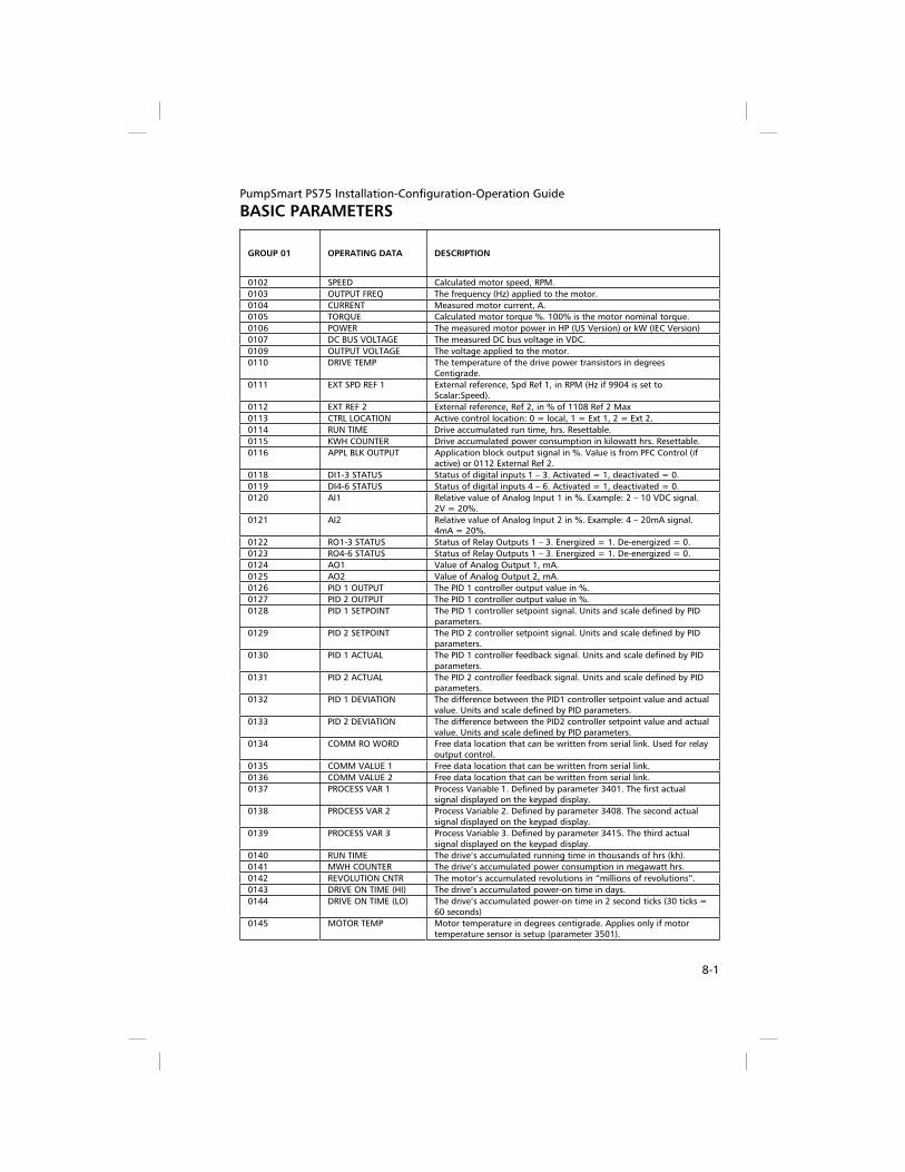
PumpSmart PS75 Installation-Configuration-Operation Guide
BASIC PARAMETERS
8-1
GROUP 01 OPERATING DATA DESCRIPTION
0102 SPEED Calculated motor speed, RPM.
0103 OUTPUT FREQ The frequency (Hz) applied to the motor.
0104 CURRENT Measured motor current, A.
0105 TORQUE Calculated motor torque %. 100% is the motor nominal torque.
0106 POWER The measured motor power in HP (US Version) or kW (IEC Version)
0107 DC BUS VOLTAGE The measured DC bus voltage in VDC.
0109 OUTPUT VOLTAGE The voltage applied to the motor.
0110 DRIVE TEMP The temperature of the drive power transistors in degrees Centigrade.
0111 EXT SPD REF 1 External reference, Spd Ref 1, in RPM (Hz if 9904 is set to Scalar:Speed).
0112 EXT REF 2 External reference, Ref 2, in % of 1108 Ref 2 Max
0113 CTRL LOCATION Active control location: 0 = local, 1 = Ext 1, 2 = Ext 2.
0114 RUN TIME Drive accumulated run time, hrs. Resettable.
0115 KWH COUNTER Drive accumulated power consumption in kilowatt hrs. Resettable.
0116 APPL BLK OUTPUT Application block output signal in %. Value is from PFC Control (if active) or 0112 External Ref 2.
0118 DI1-3 STATUS Status of digital inputs 1 – 3. Activated = 1, deactivated = 0.
0119 DI4-6 STATUS Status of digital inputs 4 – 6. Activated = 1, deactivated = 0.
0120 AI1 Relative value of Analog Input 1 in %. Example: 2 – 10 VDC signal. 2V = 20%.
0121 AI2 Relative value of Analog Input 2 in %. Example: 4 – 20mA signal. 4mA = 20%.
0122 RO1-3 STATUS Status of Relay Outputs 1 – 3. Energized = 1. De-energized = 0.
0123 RO4-6 STATUS Status of Relay Outputs 1 – 3. Energized = 1. De-energized = 0.
0124 AO1 Value of Analog Output 1, mA.
0125 AO2 Value of Analog Output 2, mA.
0126 PID 1 OUTPUT The PID 1 controller output value in %.
0127 PID 2 OUTPUT The PID 1 controller output value in %.
0128 PID 1 SETPOINT The PID 1 controller setpoint signal. Units and scale defined by PID parameters.
0129 PID 2 SETPOINT The PID 2 controller setpoint signal. Units and scale defined by PID parameters.
0130 PID 1 ACTUAL The PID 1 controller feedback signal. Units and scale defined by PID parameters.
0131 PID 2 ACTUAL The PID 2 controller feedback signal. Units and scale defined by PID parameters.
0132 PID 1 DEVIATION The difference between the PID1 controller setpoint value and actual value. Units and scale defined by PID parameters.
0133 PID 2 DEVIATION The difference between the PID2 controller setpoint value and actual value. Units and scale defined by PID parameters.
0134 COMM RO WORD Free data location that can be written from serial link. Used for relay output control.
0135 COMM VALUE 1 Free data location that can be written from serial link.
0136 COMM VALUE 2 Free data location that can be written from serial link.
0137 PROCESS VAR 1 Process Variable 1. Defined by parameter 3401. The first actual signal displayed on the keypad display.
0138 PROCESS VAR 2 Process Variable 2. Defined by parameter 3408. The second actual signal displayed on the keypad display.
0139 PROCESS VAR 3 Process Variable 3. Defined by parameter 3415. The third actual signal displayed on the keypad display.
0140 RUN TIME The drive’s accumulated running time in thousands of hrs (kh).
0141 MWH COUNTER The drive’s accumulated power consumption in megawatt hrs.
0142 REVOLUTION CNTR The motor’s accumulated revolutions in “millions of revolutions”.
0143 DRIVE ON TIME (HI) The drive’s accumulated power-on time in days.
0144 DRIVE ON TIME (LO) The drive’s accumulated power-on time in 2 second ticks (30 ticks = 60 seconds)
0145 MOTOR TEMP Motor temperature in degrees centigrade. Applies only if motor temperature sensor is setup (parameter 3501).

PumpSmart PS75 Installation-Configuration-Operation Guide
BASIC PARAMETERS
8-2
GROUP 04 FAULT HISTORY DESCRIPTION
0401 LAST FAULT Fault code of the last fault
0402 FAULT TIME 1 The day on which the last fault occurred. Either as: a date if real time clock is operating or number of days after power on – if real time clock is not used or set.
0403 FAULT TIME 2 The day on which the last fault occurred. Either as: hh:mm:ss if real time clock is operating or the time since power on (less the whole days in 0402) in format hh:mm:ss – if real time clock is not used or set.
0404 SPEED AT FAULT Motor speed (Rpm) at time last fault occurred.
0405 FREQ AT FAULT The frequency (Hz) at time last fault occurred.
0406 VOLTAGE AT FAULT The DC bus voltage (V) at time last fault occurred.
0407 CURRENT AT FAULT The motor current (A) at time last fault occurred.
0408 TORQUE AT FAULT The motor torque (%) at time last fault occurred.
0409 STATUS AT FAULT The drive status (hex code word) at time last fault occurred.
0410 DI1-3 AT FAULT The status of digital inputs 1-3 at time last fault occurred.
0411 DI4-6 AT FAULT The status of digital inputs 4-6 at time last fault occurred.
0412 PREVIOUS FAULT 1 Fault code of the second last fault.
0413 PREVIOUS FAULT 2 Fault code of third last fault.
GROUP 10 START/STOP/DIR DESCRIPTION
EXT 1 COMMANDS Defines the configuration of start/stop for external control location 1 (EXT 1) used for Start-Up “Speed Control Mode”. PS75 selections are:
0=Not Sel Not Selected.
1=2W DI1 2 wire start/stop through DI1
3=3W DI1P,2P 3-wire pulse start through DI1: 0>1 Start. Pulse stop through DI2: 1>0: Stop
8=Keypad Start/stop from the keypad in (REM) mode. [default for Startup “Speed Control”]
1001
10=Comm Start/stop via fieldbus control word
EXT 2 COMMANDS Defines the configuration of start/stop for external control location 2 (EXT 2) used for “Process Control Mode”. PS75 selections are:
0=Not Sel Not Selected.
1=2W DI1 2 wire start/stop through DI1
3=3W DI1P,2P 3-wire pulse start through DI1: 0>1 Start. Pulse stop through DI2: 1>0: Stop
8=Keypad Start/stop from the keypad in (REM) mode. [default for “Process
Control”]
1002
10=Comm Start/stop via fieldbus control word
DIRECTION Defines the control of motor rotation direction.
1= Forward [default] Rotation is fixed in forward direction
2= Reverse Rotation is fixed in reverse direction
1003
3= Request Rotation direction can be changed on command. Applies to (LOC) control and (REM) Keypad control only.
MOTOR JOG Motor jogs at 60 RPM for 15 seconds
Disabled [Default] Motor jog is not active
1004
Jog Jogs motor for 15 sec at 60 rpm. After jog is complete this parameter returns to disabled.

PumpSmart PS75 Installation-Configuration-Operation Guide
BASIC PARAMETERS
8-3
GRP 11 REFERENCE SELECT DESCRIPTION
SPD REF 1 SEL Selects the source of the speed reference (setpoint). PS75 selections are:
0=Keypad [default] The setpoint is set from the keypad.
1=AI1 The setpoint is set from analog input 1
2=AI2 The setpoint is set from analog input 2
1103
8=Comm The setpoint is sent via fieldbus control word
1104 SPD REF I MIN Sets the minimum speed in Rpm or Hz (in scalar speed mode) for the reference source. If sending an analog signal the minimum analog input signal (mA or V) corresponds to Spd Ref 1 Min. [Default is 0]
1105 SPD REF 1 MAX Sets the maximum speed in Rpm or Hz (in scalar speed mode) for the reference source. If sending an analog signal the maximum analog input signal (mA or V) corresponds to Spd Ref 1 Max. [Default is
9908 Motor Nominal Speed]
REF 2 SELECT Selects the signal source for external reference Ref 2 Min and Ref 2 Max.
0=Keypad The setpoint is set from the keypad.
1=AI1 The setpoint is set from analog input 1
2=AI2 The setpoint is set from analog input 2
8=Comm The setpoint is sent via fieldbus control word
1106
19=PID1 OUT The reference is taken from PID 1 Output. Refer to Group 40. [default Process Control].
1107 REF 2 MIN Sets the minimum for External Reference 2. The minimum analog input signal corresponds to Ref 2 Min in %. The value is a % of maximum speed (frequency) or maximum process reference. [Default
is 0%]
1108 REF 2 MAX Sets the maximum for External Reference 2. The maximum analog input signal corresponds to Ref 2 Max in %. The value is a % of maximum speed (frequency) or maximum process reference. [Default
is 100%]
GRP 12 CONSTANT SPEEDS DESCRIPTION
CONST SPEED SEL Defines the digital inputs to select Constant Speeds
0=Not Sel Not Selected.
1201
9=DI3/DI4 Selects one of three Constant Speeds using DI3 and DI4. If both digital inputs are deactivated there is no constant speed selected. Activation of DI3 selects constant speed 1 (1201). Activation of DI4 selects constant speed 2 (1203). Activation of DI3 and DI4 selects constant speed 3 (1204). [default for Startup “Speed Control”]
1202 CONST SPEED 1 Sets value range for Constant Speed 1. [Default 2001 Minimum
Speed]
1203 CONST SPEED 2 Sets value range for Constant Speed 2. [Default 2001 Minimum
Speed]
1204 CONST SPEED 3 Sets value range for Constant Speed 3. [Default 2001 Minimum
Speed]

PumpSmart PS75 Installation-Configuration-Operation Guide
BASIC PARAMETERS
8-4
GRP 13 ANALOG INPUTS DESCRIPTION
1301 MINIMUM AI1 Defines the minimum value of analog input 1. Defines the value as a % of the full analog signal range. Example: 4 mA is 20% (4 mA/20 mA * 100). The minimum analog input signal corresponds to 1104 Spd Ref 1 Min and 1107 Ref 2 Min. [Default is 20%]
1304 MINIMUM AI2 Defines the minimum value of analog input 2. Defines the value as a % of the full analog signal range. Example: 4 mA is 20% (4 mA/20 mA * 100). The minimum analog input signal corresponds to 1104 Spd Ref 1 Min and 1107 Ref 2 Min. [Default is 20%]

PumpSmart PS75 Installation-Configuration-Operation Guide
BASIC PARAMETERS
8-5
GRP 14 RELAY OUTPUTS DESCRIPTION
RELAY OUTPUT 1 Defines the condition that activates relay 1. Selections are:
0= Not Sel Relay is not used and is de-energized.
1=Ready [default] Relay energizes when drive is ready to run. Run enable is present, no faults exist, supply voltage is within range and E-Stop is satisfied (if present).
2=Run Energize relay when the drive is running.
3=Fault(-1) Energize relay when power is applied. De-energizes when a fault occurs.
4=Fault Relay energizes when a fault occurs.
5=Alarm Relay energizes when an alarm is active.
15=Fault (Rst) The relay energizes when the drive is in a fault condition and will reset after the Reset Delay (3103).
16=Flt/Alarm The relay energizes when a fault or alarm occurs.
21=Overcurrent Energize the relay after an Overcurrent alarm or fault occurs.
22=Overvoltage Energize the relay after an Overvoltage alarm or fault occurs.
23=Drive Temp Energize the relay when a Drive Overtemperature alarm or fault occurs.
24=Undervoltage Energize the relay after an Undervoltage alarm or fault occurs.
25=Sens Err AI1 Energize relay when AI1 signal is lost.
26=Sens Err AI2 Energize relay when AI2 signal is lost.
27=Motor Temp Energize the relay when a Motor Overtemperature alarm or fault occurs.
28=Stall Energize relay when a stall alarm or fault occurs.
29=Underload Energize the relay when a Underload alarm or fault occurs.
30=PID Sleep Energize relay when PID sleep function is active.
1401
31=PFC Use relay to start/stop the motor in PFC Control.
RELAY OUTPUT 2 Defines the condition that activates relay 2. Selections are:
0= Not Sel Relay is not used and is de-energized.
1=Ready Relay energizes when drive is ready to run. Run enable is present, no faults exist, supply voltage is within range and E-Stop is satisfied (if present).
2=Run [default] Energize relay when the drive is running.
3=Fault(-1) Energize relay when power is applied. De-energizes when a fault occurs.
4=Fault Relay energizes when a fault occurs.
5=Alarm Relay energizes when an alarm is active.
15=Fault (Rst) The relay energizes when the drive is in a fault condition and will reset after the Reset Delay (3103).
16=Flt/Alarm The relay energizes when a fault or alarm occurs.
21=Overcurrent Energize the relay after an Overcurrent alarm or fault occurs.
22=Overvoltage Energize the relay after an Overvoltage alarm or fault occurs.
23=Drive Temp Energize the relay when a Drive Overtemperature alarm or fault occurs.
24=Undervoltage Energize the relay after an Undervoltage alarm or fault occurs.
25= Sens Err AI1 Energize relay when AI1 signal is lost.
26= Sens Err AI2 Energize relay when AI2 signal is lost.
27=Motor Temp Energize the relay when a Motor Overtemperature alarm or fault occurs.
28=Stall Energize relay when a stall alarm or fault occurs.
29=Underload Energize the relay when a Underload alarm or fault occurs.
30=PID Sleep Energize relay when PID sleep function is active.
1402
31=PFC Use relay to start/stop the motor in PFC Control.

PumpSmart PS75 Installation-Configuration-Operation Guide
BASIC PARAMETERS
8-6
GRP 14 RELAY OUTPUTS DESCRIPTION
RELAY OUTPUT 3 Defines the condition that activates relay 3. Selections are:
0= Not Sel Relay is not used and is de-energized.
1=Ready Relay energizes when drive is ready to run. Run enable is present, no faults exist, supply voltage is within range and E-Stop is satisfied (if present).
2=Run Energize relay when the drive is running.
3=Fault(-1) Energize relay when power is applied. De-energizes when a fault occurs.
4=Fault [default] Relay energizes when a fault occurs.
5=Alarm Relay energizes when an alarm is active.
15=Fault (Rst) The relay energizes when the drive is in a fault condition and will reset after the Reset Delay (3103).
16=Flt/Alarm The relay energizes when a fault or alarm occurs.
21=Overcurrent Energize the relay after an Overcurrent alarm or fault occurs.
22=Overvoltage Energize the relay after an Overvoltage alarm or fault occurs.
23=Drive Temp Energize the relay when a Drive Overtemperature alarm or fault occurs.
24=Undervoltage Energize the relay after an Undervoltage alarm or fault occurs.
25= Sens Err AI1 Energize relay when AI1 signal is lost.
26= Sens Err AI2 Energize relay when AI2 signal is lost.
27=Motor Temp Energize the relay when a Motor Overtemperature alarm or fault occurs.
28=Stall Energize relay when a stall alarm or fault occurs.
29=Underload Energize the relay when a Underload alarm or fault occurs.
30=PID Sleep Energize relay when PID sleep function is active.
1403
31=PFC Use relay to start/stop the motor in PFC Control.
GRP 15 ANALOG OUTPUTS DESCRIPTION
AO1 CONFIG Configures a PS75 signal to analog output 1 (AO1)
102…145 Output corresponds to any parameter in Grp 01 Operating Data. [Default is 0102 Speed].
99 Excite PTC Provides a current source for sensor type PTC. Output =1.6 mA.
1501
100 Excite PT100 Provides a current source for sensor type Pt100. Output =9.1 mA.
AO2 CONFIG Configures a PS75 signal to analog output 1 (AO2)
102…145 Output corresponds to any parameter in Grp 01 Operating Data. [Default is 0104 Current].
99 Excite PTC Provides a current source for sensor type PTC. Output =1.6 mA.
1507
100 Excite PT100 Provides a current source for sensor type Pt100. Output =9.1 mA.
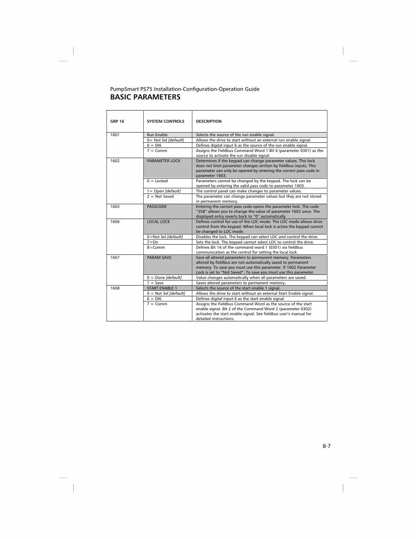
PumpSmart PS75 Installation-Configuration-Operation Guide
BASIC PARAMETERS
8-7
GRP 16 SYSTEM CONTROLS DESCRIPTION
Run Enable Selects the source of the run enable signal.
0= Not Sel [default] Allows the drive to start without an external run enable signal.
6 = DI6 Defines digital input 6 as the source of the run enable signal.
1601
7 = Comm Assigns the Fieldbus Command Word 1 Bit 6 (parameter 0301) as the source to activate the run disable signal.
PARAMETER LOCK Determines if the keypad can change parameter values. This lock does not limit parameter changes written by fieldbus inputs. This parameter can only be opened by entering the correct pass code in parameter 1603.
0 = Locked Parameters cannot be changed by the keypad. The lock can be opened by entering the valid pass code to parameter 1603.
1= Open [default] The control panel can make changes to parameter values.
1602
2 = Not Saved The parameter can change parameter values but they are not stored in permanent memory.
1603 PASSCODE Entering the correct pass code opens the parameter lock. The code “358” allows you to change the value of parameter 1602 once. The displayed entry reverts back to “0” automatically
LOCAL LOCK Defines control for use of the LOC mode. The LOC mode allows drive control from the keypad. When local lock is active the keypad cannot be changed to LOC mode.
0=Not Sel [default] Disables the lock. The keypad can select LOC and control the drive.
7=On Sets the lock. The keypad cannot select LOC to control the drive.
1606
8=Comm Defines Bit 14 of the command word 1 (0301) via fieldbus communication as the control for setting the local lock.
PARAM SAVE Save all altered parameters to permanent memory. Parameters altered by fieldbus are not automatically saved to permanent memory. To save you must use this parameter. If 1602 Parameter Lock is set to “Not Saved”. To save you must use this parameter.
0 = Done [default] Value changes automatically when all parameters are saved.
1607
1 = Save Saves altered parameters to permanent memory.
START ENABLE 1 Selects the source of the start enable 1 signal.
0 = Not Sel [default] Allows the drive to start without an external Start Enable signal.
6 = DI6 Defines digital input 6 as the start enable signal.
1608
7 = Comm Assigns the Fieldbus Command Word as the source of the start enable signal. Bit 2 of the Command Word 2 (parameter 0302) activates the start enable signal. See fieldbus user’s manual for detailed instructions.

PumpSmart PS75 Installation-Configuration-Operation Guide
BASIC PARAMETERS
8-8
GRP 19 PROTECTION DESCRIPTION
CONFIG_SPD_MIN Defines the reaction of the drive during a Pump Protect or Min Flow “Alarm and Control” condition.
Spd=Min Spd
If an “Alarm and Control” condition is detected the PS75 will drop to parameter 2001 Minimum Speed between parameter 3101 Error Resets. If the condition is not corrected and all reset trials have been exhausted the drive will fault. If parameter 3101 Error Reset is set to zero the drive will fault once an “Alarm and Control” condition is detected.
1901
Spd=0 [default]
The PS75 will shutdown and fault if an “Alarm and Control” condition is detected. If parameter 3101 Error Reset is set to “n” resets then the drive will restart after the parameter 3103 Reset Delay Time. If the condition is not corrected and all reset trials have been exhausted the drive will fault. If parameter 3101 Error Reset is set to zero the drive will fault once an “Alarm and Control” condition is detected.
PUMP_PROTECT
If parameter 4005 is set to “Normal“ and actual process value is lower than protection limit (1903) for protection delay (1904) and PS75 is at (2002) max speed for the protection delay a pump protect condition occurs. If parameter 4005 is set to “Inverse” and actual process value is >= [1/protection limit * PV ref] for the protection delay a pump protect condition occurs.
Disabled (default) Protection is disabled
AlarmThe PS75 generates a warning only “Pump Protect”; no other action is taken unless Group 14 Relay Outputs are configured.
1902
Alarm & Ctrl The PS75 generates a warning “Pump Protect” and controls according to the setting of Config Speed Min (1901).
1903
PROTECT_LIMIT
This is the protection limit for the process value at which Pump Protect (1902) activates when pump is at (2002) max speed for the protection delay (1904). Setting range: 0 – 100% of setpoint. The default setting is 97%.
1904 PROTECT_DELAY
This is the protection delay period prior to activation of Pump Protect (1902). Setting = 0 – 200 sec. Default setting is “0 sec”.
1905 BEP_POWER
Value range setting is 0 - 9999. Defines the power at best efficiency point of the pump. The default is 90% of the motor nominal power
HP or kW (parameter 9909).
1906 PWR_OFFSET
This is a mechanical power loss offset value (e.g. seal losses). Default
value is 0.5 hp/0.0 kW. Units are same as in 9909. (Hp or kW).
1907 BEP_SPEED
Value range setting is 50 – 18000. Defines the pump speed associated with the Bep power. The default is Motor Nom Rpm
(parameter 9908).
MIN_FLOW_CTLIf enabled and the actual torque is less than the min flow torque (corrected for speed) for the protection delay 1904 a minimum flow condition is detected.
Disabled [default] Protection is disabled
WarningThe PS75 generates a “Min Flow Warning” only; no other action is taken unless Group 14 Relay Outputs are configured.
1908
Alarm & Control The PS75 generates a “Min Flow” warning or fault and controls according to the setting of Config Spd Min (1901). The fault is resettable if Error Reset (3101) is active.
1909 MIN_FLOW_TRQ
Value range setting is 0 – 200%. The default is 0%. This is the min flow torque expressed as a % of Bep Torque.
DRY _RUN_CTL If enabled and the actual torque is less than the dry run torque (corrected for speed) for the protection delay 1904 a dry run condition is detected.
Disabled [default] Protection is disabled
WarningThe PS75 generates a “Dry Run Warning” only; no other action is taken unless Group 14 Relay Outputs are configured.
1910
FaultThe drive trips on fault and the motor coasts to a stop. A fault message is generated “Dry Run”. This fault is not resettable by Error Reset (3101)

PumpSmart PS75 Installation-Configuration-Operation Guide
BASIC PARAMETERS
8-9

PumpSmart PS75 Installation-Configuration-Operation Guide
BASIC PARAMETERS
8-10
GRP 19 PROTECTION DESCRIPTION
1911 DRY_RUN_TRQ
Value range setting is 0 – 200%. The default is 0%. This is the Dry Run Torque expressed as a % of Bep Torque.
RUNOUT_CTLIf enabled and the actual torque is greater than the run out torque (corrected for speed) for the protection delay 1904 a run out condition is detected.
Disabled [default] Protection is disabled
WarningThe PS75 generates a “Run Out Warning” only; no other action is taken unless Group 14 Relay Outputs are configured.
1912
Alarm & Control
The unit will issue a warning and decrease speed enough so the actual torque is equal to the runout torque (corrected for speed). The ramp rate can be adjusted by setting of parameter 1914. This warning is resettable by Error Reset (3101) and Reset Delay (3103) after the unit has reached min speed (2001). Once all parameter 3101 Error Resets have been exhausted the drive will remain at (2001) Min Speed until manually shutdown (unless a fault occurs).
1913 RUNOUT_TRQ
Value range setting is 0 – 200%. Default is 200%. This is the Runout torque expressed as a % of Bep torque.
1914 RUNOUT_ RAMP
Settable deceleration ramp during Runout warning. Default is 20
sec. Range equals 5 - 100 sec.
1915 CALC_ TEST_ TRQ
The actual Torque/Corr BEP Trq expressed as a %. This is the operating % which is compared to the 1909, 1911 and 1913 settings. Useful during setup. Viewable only. Write Protected.
GRP 20 LIMITS DESCRIPTION
2001 MINIMUM SPEED Defines the allowable minimum speed. The default setting is 25% of
9908 motor nominal speed.
2002 MAXIMUM SPEED Defines the maximum allowable speed. The default is 9908 Motor
Nominal Speed.
GRP 21 START/STOP DESCRIPTION
STOP FUNCTION Selects how the motor should stop under normal conditions.
1 = Coast [default] Power is cut immediately to the motor allowing it to coast to a stop.
2102
2= Ramp Pump shutsdown using the ramp rate defined in parameter 2203 DECELER TIME 1.
GRP 22 ACCEL/DECEL DESCRIPTION
2202 ACCELER TIME 1 Sets the acceleration time for zero to maximum speed for ramp pair 1. Range 0-1800 sec. Default is 5 sec.
2203 DECELER TIME 1 Sets the deceleration time from maximum speed to zero for ramp pair 1. Range 0-1800 sec. Default is 5 sec.

PumpSmart PS75 Installation-Configuration-Operation Guide
BASIC PARAMETERS
8-11
GRP 25 CRITICAL SPEEDS DESCRIPTION
CRIT SPEED SEL Sets the critical speed function on or off. The critical speed function avoids specified speed ranges. Used for speed control mode only.
0 = Off [default] Disables the critical speed function.
2501
1= On Enables the critical speed function.
2502 CRIT SPEED 1 LO Sets the minimum limit for critical speed range 1. The value must be less than or equal to 2503 Crit Spd 1 Hi. Units are in rpm unless parameter 9904 is set to scalar: speed mode. Range is 0 – 30000 rpm (0 – 500 Hz). Default value is 0.
2503 CRIT SPEED 1 HI Sets the maximum limit for critical speed range 1. The value must be greater than or equal to 2502 Crit Spd 1 Lo. Units are in rpm unless parameter 9904 is set to scalar: speed mode. Range is 0 – 30000 rpm (0 – 500 Hz). Default value is 0.
2504 CRIT SPEED 2 LO Sets the minimum limit for critical speed range 2. The value must be less than or equal to 2505 Crit Spd 2 Hi. Units are rpm unless parameter 9904 is set to scalar: speed mode. Range is 0 – 30000 rpm (0 – 500 Hz). Default value is 0.
2505 CRIT SPEED 2 HI Sets the maximum limit for critical speed range 2. The value must be greater than or equal to 2504 Crit Spd 2 Lo. Units are in rpm unless parameter 9904 is set to scalar: speed mode. Range is 0 – 30000 rpm (0 – 500 Hz). Default value is 0.

PumpSmart PS75 Installation-Configuration-Operation Guide
BASIC PARAMETERS
8-12
GRP 30 FAULT FUNCTIONS DESCRIPTION
SENSOR FAILURE Defines the drive response if the analog input signal drops below 3 mA or 1.5 VDC. Parameters 3021 AI1 Fault Limit and 3022 AI2 Fault Limit set the fault limits.
0=Not Sel Disables response.
1 = Fault Displays a fault “Sensor Err AI1 or Sensor Err AI2” and the drive coasts to a stop.
3001
3 = Last Speed [default]
Displays a warning “Sensor Err AI1 or Sensor Err AI2” and the drive runs at an average speed over the last 10 seconds.
KEYPAD FAILURE Defines the drive response to a keypad failure.
1 = Fault Displays a fault “Keypad Fail” and the drive coasts to a stop.
3002
3 = Last Speed [default]
Displays a warning “Keypad Fail” and the drive runs at an average speed over the last 10 seconds. Warning! If you select Last Speed,
make sure that continued operation is safe when the keypad communication is lost.
SECONDARY PROT A Defines the Secondary Protect A signal input and the drive response to a Secondary Protect fault.
0 = Not Sel [default] The Secondary Protect function is not used.
1= DI3 4= DI4 5= DI5
Defines digital input 3, 4 or 5 as the Secondary Protect A function. Although any available digital input can be used. Activating the digital input indicates a fault. The drive displays a Secnd Protect A fault and the drive coasts to a stop. This function can be auto reset by parameter 3108 ER Secnd Protect.
3003
-1= DI3 (INV) -4= DI4 (INV) -5= DI5 (INV)
Defines an inverted digital input 3, 4 or 5 as the Secondary Protect A function. Although any available digital input can be used. De-activating the digital input indicates a fault. The drive displays a Secnd Protect A fault and the drive coasts to a stop. This function can be auto reset by parameter 3108 ER Secnd Protect.
SECONDARY PROT B Defines the Secondary Protect B signal input and the drive response to a Secondary Protect fault.
0 = Not Sel [default] The Secondary Protect function is not used.
1= DI3 4= DI4 5= DI5
Defines digital input 3, 4 or 5 as the Secondary Protect B function. Although any available digital input can be used. Activating the digital input indicates a fault. The drive displays a Secnd Protect B fault and the drive coasts to a stop. This function can be auto reset by parameter 3108 ER Secnd Protect.
3004
-1= DI3 (INV) -4= DI4 (INV) -5= DI5 (INV)
Defines an inverted digital input 3, 4 or 5 as the Secondary Protect B function. Although any available digital input can be used. De-activating the digital input indicates a fault. The drive displays a Secnd Protect B fault and the drive coasts to a stop. This function can be auto reset by parameter 3108 ER Secnd Protect.
GRP 31 AUTOMATIC RESET DESCRIPTION
3101 ERROR RESET Sets the number of allowed automatic resets. The selection range is 0 – 5. The zero setting disables this function [default]. The time between resets is set by parameter 3103 Reset Delay. Parameter 3102 Trial Time sets the time period for counting and limiting the number of resets [default is 60 sec]. Manual intervention is required if fault is still active after set number of resets has been achieved. Error Reset is applicable to parameters 1902, 1908, 1912 and 3104 – 3108.
3103 RESET DELAY Sets the delay time between a fault detection and attempted drive restart. Setting range is 120 sec. Default is 60 sec.

PumpSmart PS75 Installation-Configuration-Operation Guide
BASIC PARAMETERS
8-13
GRP 33 INFORMATION DESCRIPTION
3301 PS75 VERSION Contains the version of the drive’s firmware. Current version is V2.0
3302 LP VERSION Contains the version of the loading package
3303 TEST DATE Contains the test date (yy.ww)
3304 DRIVE RATING Indicates the drive’s current and voltage rating. The format is XXXY, where: XXX = the normal current rating of the drive in amps. If present an “A” indicates a decimal point in the rating for the current. For example, XXX = 8A8 indicates a nominal current rating of 8.8 amps. Y = the voltage rating of the drive, where: 2 indicates a 208…240 volt rating. 4 indicates a 380 …480 volt rating.
GRP 34 PANEL DISPLAY PROCESS VARIABLES
DESCRIPTION
SIGNAL 1 PARAM Selects the first parameter (by parameter number) displayed on the keypad. Any Grp 01 parameter can be displayed. Using parameters 3402 – 3407, the display can be scaled, converted to other units and/or displayed as a bar graph. The default for Startup “Speed
Control” and Process Control modes is 0102 Speed in Rpm.
100 Not selected. The first parameter is not displayed.
3401
101….145 Selection displays the selected Grp 01 parameter.
SIGNAL 2 PARAM Selects the second parameter (by parameter number) displayed on the keypad. Any Grp 01 parameter can be displayed. Using parameters 3409 – 3414, the display can be scaled, converted to other units and/or displayed as a bar graph. The default for Startup
“Speed Control” mode is 0111 External Spd Ref 1 in Rpm. The
default for Process Control mode is 0128 PID 1 Setpoint in units
selected by parameter 4006.
100 Not selected. The first parameter is not displayed.
3408
101….145 Selection displays the selected Grp 01 parameter.
SIGNAL 3 PARAM Selects the third parameter (by parameter number) displayed on the keypad. Any Grp 01 parameter can be displayed. Using parameters 3416 – 3421, the display can be scaled, converted to other units and/or displayed as a bar graph. The default for Startup “Speed
Control” mode is 0104 Current, Amps. The default for Process
Control mode is 0130 PID 1 ACTUAL in units selected by parameter
4006.
100 Not selected. The first parameter is not displayed.
3415
101….145 Selection displays the selected Grp 01 parameter.

PumpSmart PS75 Installation-Configuration-Operation Guide
BASIC PARAMETERS
8-14
GRP 40 PROCESS PID SET 1 DESCRIPTION
4001 GAIN Defines the PID controller’s gain. The setting range is 0.1….100. The
defaults for Process Control mode are as follows:
PID Std: 1.0
PID Inv: 25
4002 INTEGRATION TIME Defines the PID controller’s integration time. The setting range is 0.1….3600 sec. A setting of zero disables the integration time. The
defaults for Process Control mode are as follows:
PID Std: 0.7 sec
PID Inv: 150 sec
REGULATION MODE Selects either a normal or inverse relationship between the feedback signal and drive speed.
0= Normal Increases the output speed with falling process variable signal. For level control applications the tank is on the discharge side. [default
for PID Std]
4005
1 = Inverse Decreases the output speed with falling process variable signal. For level control applications the tank is on the suction side. [default for
PID INV]
UNITS Selects the units for the PID controller actual values. The most common units for PS75 are:
0= Not selected
4= % [default]
9= C
16= F
20= M3/H
22= Bar
24= GPM
25= PSI
27= Ft
28= M
41= Kg/s
42= Kg/m
43= Kg/h
53= Lb/s
54= Lb/m
4006
55= Lb/h
Selects the units for the primary process transmitter connected at AI2.
4008 0% PV SCALE This is the reading of the primary process transmitter that corresponds to it’s 4 mA signal. Units are the same as in parameter 4006. The default is 0.
4009 100% PV SCALE This is the reading of the primary process transmitter that corresponds to it’s 20 mA (full scale) signal. Units are the same as in parameter 4006. [default is 100]
SETPOINT SEL Defines the source from which the drive reads the signal that selects the setpoint.
0= Keypad [default] The setpoint is set using the keypad.
1= AI1 Analog input 1 provides the reference.
8= Comm Fieldbus provides the reference
4010
19=Internal A constant value set using parameter 4011 provides the reference.
SLEEP SELECTION Defines the control for the PID sleep function.
0= Not Sel [default] Disables the PID sleep function.
4022
7= Internal Uses the output rpm, process reference and process actual value as the control for the PID sleep function.
4023 PID SLEEP SPEED Sets the motor speed that enables the PID sleep function. A motor speed below this level for at least the time period 4024 PID Sleep delay enables the PID sleep function which stops the drive. Range is 0-7200 rpm. Default value is 0.

PumpSmart PS75 Installation-Configuration-Operation Guide
BASIC PARAMETERS
8-15
GRP 40 PROCESS PID SET 1 DESCRIPTION
4024 PID SLEEP DELAY Sets the time delay for the PID sleep function – a motor speed below the 4023 PID Sleep Speed for at least this time period enables the PID sleep function. Range is 0 – 3600 sec. The default is 2 sec.
4025 WAKE-UP DEV Defines the wake-up deviation - a deviation from the setpoint greater than this value for at least the time period 4026 Wake-up Delay, restarts the drive. The units are defined by parameter 4006. In normal mode (4005) Wake-up Level = Setpoint – Wake-up Deviation. In inverse mode (4005) Wake-up Level = Setpoint + Wake-up Deviation. Default value is 0.
4026 WAKE-UP DELAY Defines the wake-up delay – a deviation from the setpoint greater than 4025 wake-up deviation, for at least this time period, restarts the drive. The range is 0 – 60 sec. The default is 0.5 sec.
GROUP 99 START-UP DATA DESCRIPTION
LANGUAGE Selects the display language. The default units of power for US model drives is hp. For IEC drive models the default units of power is kW.
1= English(Am) Selects American English. [default for US models]
0= English Selects British English. [default for IEC models]
4= Espanol Selects Spanish.
2= Deutsch Selects German.
9901
7= Francais Selects French.
9905 MOTOR NOM VOLT Defines the nominal motor voltage. Equal to the value on the motor nameplate.
9906 MOTOR FL CURR Defines the nominal motor current. Equal to the value on the motor nameplate.
9907 MOTOR NOM FREQ Defines the nominal motor frequency. Typically 50 or 60 hz. Equal to the value on the motor nameplate.
9908 MOTOR NOM SPEED Defines the nominal motor speed. Equal to the value on the motor nameplate.
9909 MOTOR NOM PWR Defines the nominal motor power. Equal to the value on the motor nameplate.

PS75 - Basic Wiring - Start Up (Speed Control)
Example2 Wire START/STOP
ExampleRun Enable
!! NOTE !!
All instrumentation shielding mustbe terminated at terminal X1 -1
OPTION: 2-10VDC Speed Signal Using Drive 10V Reference
Voltage
Change parameter 1103 to “AI1” (1)
OPTION: External 4-20mA Speed Signal
DI3 DI4 OUTPUT
0 0 Speed setpoint set via
parameter 1103 setting
1 0 Selects constant speed 1
(parameter 1202)
0 1 Selects constant speed 2
(parameter 1203)
1 1 Selects constant speed 3
(parameter 1204)
OPTION: DI3/DI4 Constant Speed Selection
0 = OPEN , 1 = CLOSEDSet AI1 DIP switch to 4-20 mA current “ON”Change parameter 1103 to “AI1” (1)
ON
(-)
(+)
I External 4-20mAspeed signal
5
SCR1
3
4
6
X1 Terminal Block
AGND (-)
AI1(+)2
+10V
AI2(+)
AGND (-)
An
alo
g I/O
1103 SPEED REFERENCE 1 SELECT(0) Keypad - (default) setpoint sent by keypad(1) AI1 - External speed reference sent by AI(8) COMM - Reference sent by fieldbus
Common Pump Smart Settings
R
5
SCR1
3
4
6
X1 Terminal Block
AGND (-)
AI1(+)2
+10V
AI2(+)
AGND (-)
An
alo
g I/O
OPTION: 3 Wire Pulse Start Pulse Stop
Change parameter 1001 setting to 3W DI 1P/2P (3)
START
STOP
+24VDC10
GND11
DCOM12
DI 113
DI 214
DI 315
DI 416
DI 517
DI 618
X1Terminal Block
Dig
ital I/O
an
d A
uxilia
ry Po
wer
Analog Output Selections
1501 AO1 Config 1507 AO2 Config
(102) Speed - Motor Speed (Rpm)
(103) Frequency - Motor Frequency (Hz)
(104) Current - Motor Current (A)
(105) Torque - Output Torque (%)
(106) Power - Motor Power in Kw
(111) Ext spd Ref 1- Speed Ref in RPM
(120) AI1 - Analog Input 1 %
(121) AI2 - Analog Input 2 %
Relay Output Selections
1401 Relay Output 11402 Relay Ouput 21403 Relay Output 3
(0) NOT SEL(1) Ready(2) Run(4) Fault(5) Alarm(14) At Setpoint(16) Fault/Alarm(20) Ref Loss
(21) Overcurrent(22) Overvoltage(23) DriveTemp(24) Undervoltage(25) AI 1 Loss(26) AI 2 Loss(27) Motor Temp(30) PID Sleep
An
alo
g I/O
Dig
ital I/O
an
d A
uxi
liary
Po
wer
Rela
y O
utp
uts
X1 Terminal Block
Signal cable shield connected internally to chassis ground
OPTIO
N
SCR1
AGND (-)3
+10V4
Analog Input 1 Ground
AI Reference Voltage: 10V+ 2%, 10mA maxused for AI1 2-10VDC signals 1K ohm < R <10K ohm
Analog Input 1, ProgrammableExternal SetpointJ1:AI1 off 2..10VDC defaultJ1:AI1 on 4..20mAInput assigned in parameter 1103
OPTIO
N
AI1 (+)2
OPTIO
N
AI2 (+)5
ON
ON
Analog Input 2, ProgrammableNOT USEDJ1:AI2 off 2..10VDCJ1:AI2 on 4..20mA defaultON
ON
OPTIO
NAO1 (+)7
AO2 (+)8
Analog Output 1, programmable 4-20mAOutput assigned in parameter 1501. Default is speed
Analog Output 2, programmable 4-20mAOutput assigned in parameter 1507. Default is current
AGND (-)9 Analog Output Ground
+24VDC10
GND11
DCOM12
Process Transmitter / DI power source24VDC / 250mA (reference to GND)Used if PumpSmart is powering the process transmitter and / ordigital inputs
AGND (-)6 Analog Input 2 Ground
DI 1132 - Wire Start / Stop.Change parameter 1001 to 2W DI 1 (1).Default is Keypad Start / stop
DI 214 Used with 3- Wire Start / Stop
DI 315 Constant Speed Selection.Selects up to 3 constant speeds.Input assigned in parameter 1201DI 416
DI 517Fault ResetInput assigned in parameter 1604
DI 618Run EnableInput assigned in parameter 1601. Default is NOT USED
RO1CCOM
19
RO1NC
20
RO2NO
21
RO2CCOM
22
RO2NC
23
RO2NO
24
RO3CCOM
25
RO3NC
26
RO3NO
27
OPTIO
N
Assignable Relay (RO1)The output of this relay is assignable byparameter 1401Default: Ready (19 and 21 connected)
Assignable Relay (RO2)The output of this relay is assignable byparameter 1402Default: Run (22 and 24 connected)
Assignable Relay (RO3)The output of this relay is assignable byparameter 1403Default: Fault (25 and 27 connected)
ON
ON
PowerFault
PE
InternalFan
SLOT 1
J2
SLOT 2
View of I/O Connection board (OMIO)
J1Dip switches for Analog
Inputs
Copyright 2005 ITT Industries
B05162A REV0
Issue-
PS75 Basic Wiring : Start Up (Speed Control)
Drawing is not to scale Checked: AES 020105
Drawn: AI 011005
SHEET 1 OF 1
ACH 550
Potentiometer 1K ohm < R < 10K ohm

An
alo
g I/O
Dig
ital I/O
an
d A
uxi
liary
Po
wer
Rela
y O
utp
uts
PS75 - Basic Wiring - Process Control (PID)Instruments Powered By PumpSmart
Example2 Wire START/STOP
X1 Terminal Block
Signal cable shield connected internally to chassis ground
OPTIO
N
SCR1
AGND (-)3
+10V4
Analog Input 1 Ground
AI Reference Voltage: 10V+ 2%, 10mA maxused for AI1 2-10VDC signals 1K ohm < R <10K ohm
Analog Input 1, ProgrammableExternal SetpointJ1:AI1 off 2..10VDC defaultJ1:AI1 on 4..20mAInput assigned in parameter 4010
OPTIO
N
AI1 (+)2
OPTIO
N
AI2 (+)5
ON
ON
Analog Input 2, ProgrammablePrimary Process TransmitterJ1:AI2 off 2..10VDCJ1:AI2 on 4..20mA defaultInput assigned in parameter 4016
ON
ON
OPTIO
NAO1 (+)7
AO2 (+)8
Analog Output 1, programmable 4-20mAOutput assigned in parameter 1501. Default is speed
Analog Output 2, programmable 4-20mAOutput assigned in parameter 1507. Default is current
AGND (-)9 Analog Output Ground
+24VDC10
GND11
DCOM12
Process Transmitter / DI power source24VDC / 250mA (reference to GND)Used if PumpSmart is powering the process transmitter and / ordigital inputs
AGND (-)6 Analog Input 2 Ground
DI 1132 - Wire Start / StopChange parameter 1002 to 2W DI 1 (1).Default is Keypad Start /Stop
DI 214 Used with 3- Wire Start / Stop
DI 315 Activation Selects PID Set2 (Dual Setpoints)
Programmable Digital Input Not UsedDI 416
DI 517Fault ResetInput assigned in parameter 1604
DI 618Run EnableInput assigned in parameter 1601. Default is NOT USED
RO1CCOM
19
RO1NC
20
RO2NO
21
RO2CCOM
22
RO2NC
23
RO2NO
24
RO3CCOM
25
RO3NC
26
RO3NO
27
OPTIO
N
Assignable Relay (RO1)The output of this relay is assignable byparameter 1401Default: Ready (19 and 21 connected)
Assignable Relay (RO2)The output of this relay is assignable byparameter 1402Default: Run (22 and 24 connected)
Assignable Relay (RO3)The output of this relay is assignable byparameter 1403Default: Fault (25 and 27 connected)
ExampleRun Enable
Expose the shield of the control wirecable and connect to terminal X1-1
Example: Pressure Control Application
P (+)
(-)
!! NOTE !!
All instrumentation shielding mustbe terminated at terminal X1 -1
4010 SETPOINT SELECT
(0) Keypad - (default) setpoint sent by keypad(1) AI1 - External setpoint sent by AI 1(8) COMM - Setpoint sent by fieldbus
Common Pump Smart Settings
OPTION: 3 Wire Pulse Start Pulse Stop
Change parameter 1002 setting to 3W DI 1P/2P (3)
Copyright 2005 ITT Industries
ON
ON
PowerFault
PE
InternalFan
SLOT 1
J2
SLOT 2
B05161A REV0
Issue-
PS75 Basic Wiring : PID Process Control
Drawing is not to scale Checked: AES 020105
Drawn: AI 011005
SHEET 1 OF 1
View of I/O Connection board (OMIO)
J1Dip switches for Analog
Inputs
OPTION: External 4-20mA Setpoint Signal
(-)
(+)
I
Example: Pressure Control Application
External 4-20mAsetpoint signal
P
(-)
(+)
5
SCR1
3
4
6
X1 Terminal Block
AGND (-)
AI1(+)2
+10V
AI2(+)
AGND (-)
Set AI1 DIP switch to 4-20 mA current “ON”Process transmitter is externally powered. Change parameter 4010 to “AI1” (1)
ON
OPTION: 2-10VDC Setpoint Signal Using Drive 10V Reference Voltage
Process transmitter is externally powered. Change parameter 4010 to “AI1” (1)
Example: Pressure Control Application
P (+)
R
5
SCR1
3
4
6
X1 Terminal Block
AGND (-)
AI1(+)2
+10V
AI2(+)
AGND (-)
(-)
Analog Output Selections
1501 AO1 Config 1507 AO2 Config
(102) Speed - Motor Speed (Rpm)
(103) Frequency - Motor Frequency (Hz)
(104) Current - Motor Current (A)
(105) Torque - Output Torque (%)
(106) Power - Motor Power in Kw
(111) Ext spd Ref 1- Speed Ref in RPM
(120) AI1 - Analog Input 1 %
(121) AI2 - Analog Input 2 %
Relay Output Selections
1401 Relay Output 11402 Relay Ouput 21403 Relay Output 3
(0) NOT SEL(1) Ready(2) Run(4) Fault(5) Alarm(14) At Setpoint(16) Fault/Alarm(20) Ref Loss
(21) Overcurrent(22) Overvoltage(23) DriveTemp(24) Undervoltage(25) AI 1 Loss(26) AI 2 Loss(27) Motor Temp(30) PID Sleep
An
alo
g I/O
An
alo
g I/O
START
STOP
+24VDC10
GND11
DCOM12
DI 113
DI 214
DI 315
DI 416
DI 517
DI 618
X1Terminal Block
Dig
ital I/O
an
d A
uxilia
ry Po
wer
Potentiometer 1K ohm < R < 10K ohm
ACH 550

W
Free Space Required for Ventilation
Installation Checklist
MECHANICAL1. Check that the ambient operating conditions are suitable [Technical Data].2. Check that the unit is mounted properly on a vertical non-flammable wall [Mechanical Installation]3. Check that cooling air flows freely4. Check the applicability of the motor and the driven equipment [Electrical Installation]
ELECTRICAL5. If the PS75 is connected to a floating network (ungrounded power system or a high impedance
network), check that RFI filter is disconnected.6. The capacitors are reformed if stored over a year.7. Check that the drive is grounded properly8. Check that the input voltage matches the drive nominal input voltage9. Check that the input power connections at U1, V1, and W1 are OK10. Check that the appropriate line fuses are installed11. Check that motor connections at U2, V2, and W2 are okay12. Check the motor cable routing13. Check that there are no power factor compensation capacitors connected between the drive and
the motor.14. Review and check that control connections inside the drive are properly wired [See control wiring
diagrams].15. Check that there are no tools or foreign objects left inside the drive.16. With bypass connection, check that input line voltage cannot be applied to the output of the
PumpSmart PS75.17. Drive, motor connection box and other covers are in place.
3.9[99]
WInches[mm]
NEMA 1/12Drill Pattern
3.9[99]
6.3[160]
6.3[160]
9.4[239]
12.5[318]
HInches[mm]
16.4[417]
18.6[472]
22.8[579]
23.2[589]
30.5[775]
NEMA12IP54
AInches [mm]
34.5[876]
39[991]
43.1[1095]
45.1[1146]
34.2[869]
NEMA1IP21
38.1[968]
40.8[1036]
45.9[1166]
46.4[1179]
R1
FrameSize
R2
R3
R4
R5
A
8.0"[203]
Control/Power Wiring Layout
Mains Cable Motor Cable
Minimum Distance12 Inches[300 mm]
Minimum Distance20 Inches[500 mm]
Keep control wiringperpendicular to
power wiring
Control Wiring
Minimum Distance8 Inches
[200 mm]
!WARNING!Review the entire hardware manual prior to
installation
Mains / Power WiringSchematic
General Notes:1- 360o Grounded terminations are required2. Ultra-rapid fuses are required to protect drive. Refer to Technical Data section for details
PE
U1 V1 W1 U2 V2 W2
L1 L2 L3
T1T2
T3
GG
GG
Metallic Conduitor Shielded
Cable
Motor3
PowerSupply
Fuse
s an
d D
isco
nn
ect
Su
pp
lied
by C
ust
om
er
The information provided on this sheet is for installationreference only. Please refer to ACH550 Installation Manual
for additional installation details
PS75 INSTALLATION QUICK REFERENCE - Wall Mount Units (ACH 550)NEMA 1 (IP21) / NEMA 12 (IP54)
Cooling Air FlowSide View
Checked: Tony Stavale
Drawn: AI 020205Drawing is not to scale
Dimensions in inches [mm]
Issue
-
PS 75 Installation Quick Reference ACH 550 Wall Mount units
REV
0SHEET 1 OF 1 B05173A
H
10.4[264]
26.6[676]
50.7[1288]
52.5[1334]
R6
Free SpaceRequirements
Overall Drive DimensionsNEMA 1 / IP21
R1
Frame Size
R2
R3
R4
R5
Overall Drive DimensionsNEMA 12 / IP54
14.5[368]
HeightInches[mm]
18.5[470]
23.0[584]
27.1[688]
29.0[736]
4.9[124]
WidthInches[mm]
4.9[124]
8.0[203]
8.0[203]
10.5[267]
8.3[211]
DepthInches[mm]
8.7[221]
9.1[231]
10.3[262]
11.3[287]
14.3[6.5]
WeightLbm[kg]
19.8[9]
35.0[16]
53.0[24]
75[34]
18.2[461]
HeightInches[mm]
22.1[561]
24.8[629]
29.9[760]
30.4[773]
8.8[222]
WidthInches[mm]
8.8[222]
10.5[267]
10.5[267]
14.5[369]
9.2[234]
DepthInches[mm]
9.6[245]
10.0[253]
11.2[284]
12.2[3.09]
18.1[8.2]
WeightLbm[kg]
24.7[11.2]
40.8[18.5]
58.4[26.5]
84.9[38.5]
R634.7[881]
11.9[302]
15.8[401]
152[69]
36.5[926]
16.1[410]
16.6[423]
190[86]
U1/V1/W1 - U2/V2/W2BRK+, UDC+ Terminals
R11
FrameSize
R21
R31
R41
R5
Min. Wire Size
0.75
mm2 AWG
0.75
2.5
10
16
Max. Wire Size
16
mm2 AWG
16
25
50
70
Torque
1.3
Nm Lb-ft
1.3
2.7
5.6
15
Max. Wire Size
16
mm2 AWG
16
25
50
70
Torque
1.3
Nm Lb-ft
1.3
2.7
5.6
15
Earthing PE Terminal
1. Do not use aluminum cable with frame size R1...R4
R6 95 185 40 185 40
MountingHole
Location
Copyright 2005 ITT Industries
NEMA 1 / IP21NEMA 12 / IP54
HP
1 , 1.5 , 23 , 5
230 VAC -Single Phase
230 VAC -Three Phase
1.5 , 2
NEMA 1 / IP21NEMA 12 / IP54
HP
NEMA 1 / IP21NEMA 12 / IP54
HP
R11.5 , 2 , 3
5 , 7.5
380 VAC 460 VAC
1.1 , 1.5 , 2.23 , 4 , 5.5
NEMA 1 / IP21NEMA 12 / IP54
KW
FrameSize
7.5 , 103 , 5R2 10 , 157.5 , 11
15 , 207.5 , 10R3 20 , 2515 , 18.5
25 , 30 , 4015 , 20R4 30 , 40 , 5022 , 30 , 37
--R5 60 , 7545
50 , 6075 , 100
-R6 100 , 125 , 15055 , 7590 , 110
Refer to HardwareManual Technical
Data for applicationguidelines outside ofthe above listed limits
IP21~NEMA1IP54~NEMA 12
5-95% RELATIVEHUMIDITY
NO CONDENSATIONNO CORROSIVE GASES
NEMA 1104oF (40oC)
MAX
5oF (-15oC)MIN
(NO FROST)
NO DIRECT SUNLIGHT
3300 Ft
6
6
3
1/0
2/0
1
1
2
4
11
6
6
3
1/0
2/0
1
1
2
4
11
350MCM
30350
MCM30
18
18
14
8
6
3/0

Form A08372A 3/05 © copyright 2005 ITT Industries, Inc.
Visit our website at www.pumpsmart.com
• Pressure or Temp Control• Multi-Pump Sequencing• Auto Load Sharing• Eliminate Control Valves
• Flow Control• Auto Shut Off• No Dry Run/Cavitation• Total Protection for Mag
Drive Pumps
• Fan, Broke, Liquor, Digester• Control Level, Pressure, Flow• Improved Headbox Control
• Level Control• Reduce Recirculation• Eliminate Valves• Reduce Horsepower
• Increase Drain Down• Control Suction Level• Control Cavitation• Eliminate Control Valves
• Handle Wide Load Swings• Multi-Pump Control• Remote Diagnostics• Reduce HP Requirements
PF700• 3-200 HP• Advanced pump
protection• Allen Bradley
Powerflex 700drive
PS200• 3-800 HP• Advanced
protection• Engineered
solution
• Maintain Constant Flow asFilters Clog
• Fewer Filter Changes• No Flow Protection
• Control Pump Output• Run Slower• Run in Pump Sweet Spot• Reduce Pump Wear
Reboiler & Bottoms Pumps
Boiler Feed
Cooling Water Transfer & Loading Paper Stock
Municipal Wastewater Filtration Slurry Pumps
APPLICATION FLEXIBILITY
OTHER PRODUCTS FROM PUMPSMART CONTROL SOLUTIONS
PS10/20• PumpSmart
Protection for fixedspeed applications
• 110-575 AC voltagesup to 999 FLA motorsizes
PS75guide 3/22/05 9:14 AM Page 2