Embed Size (px)
Citation preview
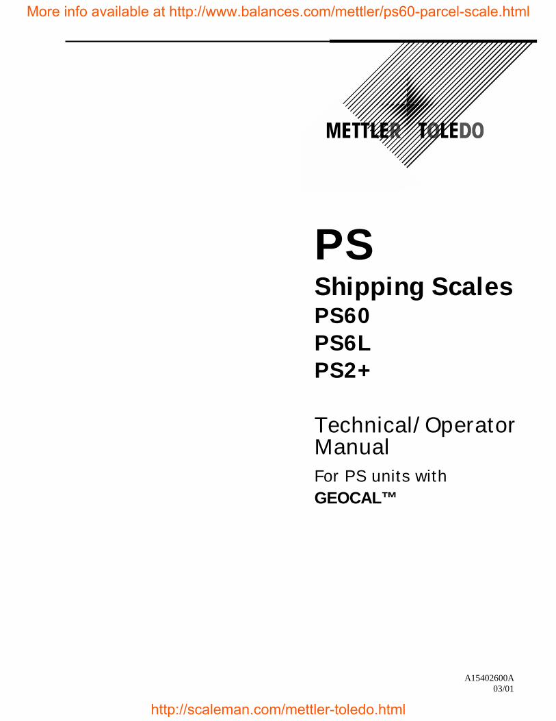
PSShipping ScalesPS60PS6LPS2+
Technical/OperatorManualFor PS units withGEOCAL™
A15402600A03/01
More info available at http://www.balances.com/mettler/ps60-parcel-scale.html
http://scaleman.com/mettler-toledo.html
INTRODUCTION
This publication is provided as a guide for individuals in the operation, use, and care of thisMETTLER TOLEDO product.
Further information or assistance regarding this product may be obtained by writing to:
METTLER TOLEDO1900 Polaris ParkwayColumbus, OH 43240-2020(614) 438-4400
WARNING!This equipment generates, uses, an can radiate radio frequency energy and if not installed andused properly, i.e., in accordance with the instructions manual, may cause harmfulinterference to radio communications. It has been tested and found to comply with the limitsfor a Class A computing device pursuant to Subpart J of Part 15 of FCC Rules, which aredesigned to provide reasonable protection against such interference when operated in acommercial environment. Operation of this equipment in a residential area may causeinterference, in which case the user at his own expense will be required to take whatevermeasures may be required to correct the interference.
METTLER TOLEDO RESERVES THE RIGHT TO MAKEREFINEMENTS OR CHANGES WITHOUT NOTICE.
More info available at http://www.balances.com/mettler/ps60-parcel-scale.html
http://scaleman.com/mettler-toledo.html
PRECAUTIONS
WARNING
DISCONNECT ALL POWER TO THIS UNITBEFORE INSTALLING, SERVICING, CLEANING,OR REMOVING THE FUSE. FAILURE TO DO SOCOULD RESULT IN BODILY HARM AND/ORPROPERTY DAMAGE.
CAUTION
OBSERVE PRECAUTIONS FORHANDLING ELECTROSTATICSENSITIVE DEVICES.
WARNING
ONLY PERMIT QUALIFIED PERSONNEL TOSERVICE THIS EQUIPMENT. EXERCISE CAREWHEN MAKING CHECKS, TESTS ANDADJUSTMENTS THAT MUST BE MADE WITHPOWER ON. FAILING TO OBSERVE THESEPRECAUTIONS CAN RESULT IN BODILY HARM.
WARNING
FOR CONTINUED PROTECTION AGAINSTSHOCK HAZARD, CONNECT TO PROPERLYGROUNDED OUTLET ONLY. DO NOT REMOVETHE GROUND PRONG.
CAUTIONBEFORE CONNECTING OR DISCONNECTING ANY INTERNALELECTRONIC COMPONENTS OR INTERCONNECTING WIRINGBETWEEN ELECTRONIC EQUIPMENT, ALWAYS REMOVE POWERAND WAIT AT LEAST THIRTY (30) SECONDS BEFORE ANYCONNECTIONS OR DISCONNECTION’S ARE MADE. FAILURE TOOBSERVE THESE PRECAUTIONS COULD RESULT IN DAMAGE TOOR DESTRUCTION OF THE EQUIPMENT, OR BODILY HARM.
READ this manual BEFOREoperating or servicing thisequipment.
FOLLOW these instructionscarefully.
SAVE this manual for futurereference.
DO NOT allow untrainedpersonnel to operate, clean,inspect, maintain, service, ortamper with this equipment.
ALWAYS DISCONNECTthis equipment from thepower source beforecleaning or performingmaintenance.
CALL METTLER TOLEDOfor parts, information, andservice.
Note: If the unit has been stored ortransported in below freezingtemperatures, allow the unit to warmup to room temperature before turningon AC power.
More info available at http://www.balances.com/mettler/ps60-parcel-scale.html
http://scaleman.com/mettler-toledo.html
CONTENTS
1111 IntroductionIntroductionIntroductionIntroduction................................................................................................................................................................................................................................................................................................................................................................................................1-11-11-11-1Standard FeaturesStandard FeaturesStandard FeaturesStandard Features................................................................................................................................................................................................................................................................................................................................................................................................................................................ 1-11-11-11-1Optional AccessoriesOptional AccessoriesOptional AccessoriesOptional Accessories ................................................................................................................................................................................................................................................................................................................................................................................................................................ 1-21-21-21-2SpecificationsSpecificationsSpecificationsSpecifications........................................................................................................................................................................................................................................................................................................................................................................................................................................................................ 1-21-21-21-2
Physical Dimensions .....................................................................................................................1-2Power Requirements .....................................................................................................................1-3Environmental Requirements........................................................................................................1-3
Standards ComplianceStandards ComplianceStandards ComplianceStandards Compliance .................................................................................................................................................................................................................................................................................................................................................................................................................... 1-41-41-41-4Electrical Interfaces ......................................................................................................................1-5
2222 Installation and CalibrationInstallation and CalibrationInstallation and CalibrationInstallation and Calibration............................................................................................................................................................................................................................................................................................................2-12-12-12-1Unpacking and SetupUnpacking and SetupUnpacking and SetupUnpacking and Setup ............................................................................................................................................................................................................................................................................................................................................................................................................................ 2-12-12-12-1
Installation.....................................................................................................................................2-1Basic InformationBasic InformationBasic InformationBasic Information ................................................................................................................................................................................................................................................................................................................................................................................................................................................ 2-42-42-42-4
The Display...................................................................................................................................2-4Keys and Navigation.....................................................................................................................2-5
Initial Calibration using GEOCAL™Initial Calibration using GEOCAL™Initial Calibration using GEOCAL™Initial Calibration using GEOCAL™.................................................................................................................................................................................................................................................................................................................................................... 2-62-62-62-6Power up Sequence .......................................................................................................................2-8
Full CalibrationFull CalibrationFull CalibrationFull Calibration ................................................................................................................................................................................................................................................................................................................................................................................................................................................................ 2-82-82-82-8Metrological Seal InstallationMetrological Seal InstallationMetrological Seal InstallationMetrological Seal Installation............................................................................................................................................................................................................................................................................................................................................................................ 2-102-102-102-10
3333 Configuring the Setup ParametersConfiguring the Setup ParametersConfiguring the Setup ParametersConfiguring the Setup Parameters ....................................................................................................................................................................................................................................................................3-13-13-13-1Basic InformationBasic InformationBasic InformationBasic Information ................................................................................................................................................................................................................................................................................................................................................................................................................................................ 3-13-13-13-1
Program Block Access ..................................................................................................................3-1Exit Setup......................................................................................................................................3-1
Configuring Setup ParametersConfiguring Setup ParametersConfiguring Setup ParametersConfiguring Setup Parameters ............................................................................................................................................................................................................................................................................................................................................................................ 3-23-23-23-2Push Button Zero Program Block .................................................................................................3-2Zero Cursor Program Block..........................................................................................................3-3Power-up Unit Program Block......................................................................................................3-3Build Program Block ....................................................................................................................3-3Alternate Units Program Block.....................................................................................................3-4Mode Program Block ....................................................................................................................3-4Filter Program Block.....................................................................................................................3-5Baud Program Block.....................................................................................................................3-5ASCII Program Block ...................................................................................................................3-5Parity Program Block....................................................................................................................3-6Stop Program Block ......................................................................................................................3-6Protocol Program Block................................................................................................................3-6Sleep Program Block ....................................................................................................................3-7GEOCAL™ Program Block .........................................................................................................3-7Calibration Program Block ...........................................................................................................3-7End Program Block.......................................................................................................................3-8
4444 Operating InstructionsOperating InstructionsOperating InstructionsOperating Instructions........................................................................................................................................................................................................................................................................................................................................4-14-14-14-1Keypad and DisplayKeypad and DisplayKeypad and DisplayKeypad and Display.................................................................................................................................................................................................................................................................................................................................................................................................................................... 4-14-14-14-1Operator FunctionsOperator FunctionsOperator FunctionsOperator Functions............................................................................................................................................................................................................................................................................................................................................................................................................................................ 4-14-14-14-1
Parcel Weighing............................................................................................................................4-2Unit Switching ..............................................................................................................................4-2Zeroing the Scale with an Empty Container .................................................................................4-2
More info available at http://www.balances.com/mettler/ps60-parcel-scale.html
http://scaleman.com/mettler-toledo.html
Repowering from Sleep................................................................................................................ 4-3
5555 Service and MaintenanceService and MaintenanceService and MaintenanceService and Maintenance.................................................................................................................................................................................................................................................................................................................... 5-15-15-15-1Cleaning and Regular MaintenanceCleaning and Regular MaintenanceCleaning and Regular MaintenanceCleaning and Regular Maintenance ................................................................................................................................................................................................................................................................................................................................................ 5-15-15-15-1TroubleshootingTroubleshootingTroubleshootingTroubleshooting............................................................................................................................................................................................................................................................................................................................................................................................................................................................ 5-15-15-15-1
Error Code Section....................................................................................................................... 5-2Wall Transformer ......................................................................................................................... 5-2Main PCB..................................................................................................................................... 5-2Blank or Half Display .................................................................................................................. 5-3No Keypad Interaction ................................................................................................................. 5-3Indicator Locked .......................................................................................................................... 5-3
Load Cell ReplacementLoad Cell ReplacementLoad Cell ReplacementLoad Cell Replacement .................................................................................................................................................................................................................................................................................................................................................................................................................... 5-35-35-35-3Installing the Battery KitInstalling the Battery KitInstalling the Battery KitInstalling the Battery Kit ................................................................................................................................................................................................................................................................................................................................................................................................................ 5-35-35-35-3Installing the Base Mount DisplayInstalling the Base Mount DisplayInstalling the Base Mount DisplayInstalling the Base Mount Display ........................................................................................................................................................................................................................................................................................................................................................ 5-75-75-75-7Installing the Ball Top Transfer PlatterInstalling the Ball Top Transfer PlatterInstalling the Ball Top Transfer PlatterInstalling the Ball Top Transfer Platter .................................................................................................................................................................................................................................................................................................................................... 5-85-85-85-8
6666 Parts and AccessoriesParts and AccessoriesParts and AccessoriesParts and Accessories .................................................................................................................................................................................................................................................................................................................................... 6-16-16-16-1PS60/PS6L Scale PartsPS60/PS6L Scale PartsPS60/PS6L Scale PartsPS60/PS6L Scale Parts ................................................................................................................................................................................................................................................................................................................................................................................................................ 6-26-26-26-2PS6L Parts ListPS6L Parts ListPS6L Parts ListPS6L Parts List ................................................................................................................................................................................................................................................................................................................................................................................................................................................................ 6-36-36-36-3PS2+ Scale PartsPS2+ Scale PartsPS2+ Scale PartsPS2+ Scale Parts.................................................................................................................................................................................................................................................................................................................................................................................................................................................... 6-46-46-46-4PS2+ Parts ListPS2+ Parts ListPS2+ Parts ListPS2+ Parts List ............................................................................................................................................................................................................................................................................................................................................................................................................................................................ 6-56-56-56-5Weight Display PartsWeight Display PartsWeight Display PartsWeight Display Parts ................................................................................................................................................................................................................................................................................................................................................................................................................................ 6-66-66-66-6
Appendix: Host InterfaceAppendix: Host InterfaceAppendix: Host InterfaceAppendix: Host Interface ........................................................................................................................................................................................................................................................................................................................................................................ 1111Communication ParametersCommunication ParametersCommunication ParametersCommunication Parameters .................................................................................................................................................................................................................................................................................................................................................................................................... 1111ProtocolsProtocolsProtocolsProtocols ............................................................................................................................................................................................................................................................................................................................................................................................................................................................................................................ 1111
ASCII Characters and Conversions.....................................................................................2Toledo Protocol Host Commands .......................................................................................4
Scale Status Byte FormatScale Status Byte FormatScale Status Byte FormatScale Status Byte Format........................................................................................................................................................................................................................................................................................................................................................................................................................ 5555Scale Confidence Byte FormatScale Confidence Byte FormatScale Confidence Byte FormatScale Confidence Byte Format............................................................................................................................................................................................................................................................................................................................................................................................ 5555Calibrate Using Host InterfaceCalibrate Using Host InterfaceCalibrate Using Host InterfaceCalibrate Using Host Interface ............................................................................................................................................................................................................................................................................................................................................................................................ 6666Configure Scale Parameters Using Host InterfaceConfigure Scale Parameters Using Host InterfaceConfigure Scale Parameters Using Host InterfaceConfigure Scale Parameters Using Host Interface.................................................................................................................................................................................................................................................................................... 7777
More info available at http://www.balances.com/mettler/ps60-parcel-scale.html
http://scaleman.com/mettler-toledo.html
Chapter 1: Chapter 1: Chapter 1: Chapter 1: IntroductionIntroductionIntroductionIntroductionStandard FeaturesStandard FeaturesStandard FeaturesStandard Features
(03/01) (03/01) (03/01) (03/01) 1-11-11-11-1
1111 IntroductionIntroductionIntroductionIntroductionThank you for purchasing a PS shipping scale from METTLER TOLEDO.
The legal-for-trade model of the PS60 shipping scale is a low-profile, 150 ×0.05 lb (60 × 0.02 kg) capacity scale designed to meet the needs of the legal-for- trade parcel/manifest markets. The PS60 also features an auto-rangingand/or weight classifying version with a capacity of 0 - 60 lb × .02 lb / 60 -150 lb × .05 lb. Both are NTEP approved. (See Chapter 3 for a complete listof builds.)
The legal-for-trade model of the PS6L shipping scale is similar to the PS60but has a higher resolution for letter weighing. It has a weight classifying,auto-ranging capacity of 0-7 lb x 0.1oz / 7-70 lb x 0.2 oz / 70–149 lb x 0.5 oz.
The PS2+ model is a large roller top scale with a capacity of 250 x 0.1 lb(100kg x 0.05kg). It is designed for parcel weighing in conveyor systems.
The PS, like all METTLER TOLEDO products is designed for maximumdurability and reliability in even the most demanding applicationenvironments. The PS is manufactured in one of METTLER TOLEDO’s tenISO 9000 certified facilities so you are assured to receive a high-qualityproduct.
The scale is designed for use in parcel shipping and other light industrialenvironments. This unit is not intended for wash-down or hazardous areaoperation, or for operation in environments of extreme dust, heat, cold, orhumidity.
In the unlikely event you experience difficulties operating your scale, pleasecontact your local distributor or METTLER TOLEDO representative fromwhom you purchased the scale.
Standard FeaturesStandard FeaturesStandard FeaturesStandard FeaturesThe following are standard features built into each PS shipping scale.
• 150 lb or 250 lb capacity “Eagle+” load cell• Die-cast aluminum base and sub-platter• Stainless steel or plastic platter• RS-232 serial interface to the scale base• Automatic power down mode for energy conservation
• 12 VDC, 60mA power supply unit (wall-mount transformer)
• 2-key weight indicator
More info available at http://www.balances.com/mettler/ps60-parcel-scale.html
http://scaleman.com/mettler-toledo.html
METTLER TOLEDO PS Shipping Scale Technical/Operators ManualMETTLER TOLEDO PS Shipping Scale Technical/Operators ManualMETTLER TOLEDO PS Shipping Scale Technical/Operators ManualMETTLER TOLEDO PS Shipping Scale Technical/Operators Manual
1-21-21-21-2 (03/01) (03/01) (03/01) (03/01)
Optional AccessoriesOptional AccessoriesOptional AccessoriesOptional Accessories• 0270, 2-key weight indicator base mount display with 12 in. cable• D-cell alkaline battery kit (for some models)• Tower display with 14 ft cable• Ball transfer top platter (standard on PS2+)• Car lighter jack• Wall mount display with 14 ft cable• Dual wall mount displays with 6 ft cable
SpecificationsSpecificationsSpecificationsSpecificationsThe PS shipping scale conforms to and operates best within the specificationsdescribed in this section.
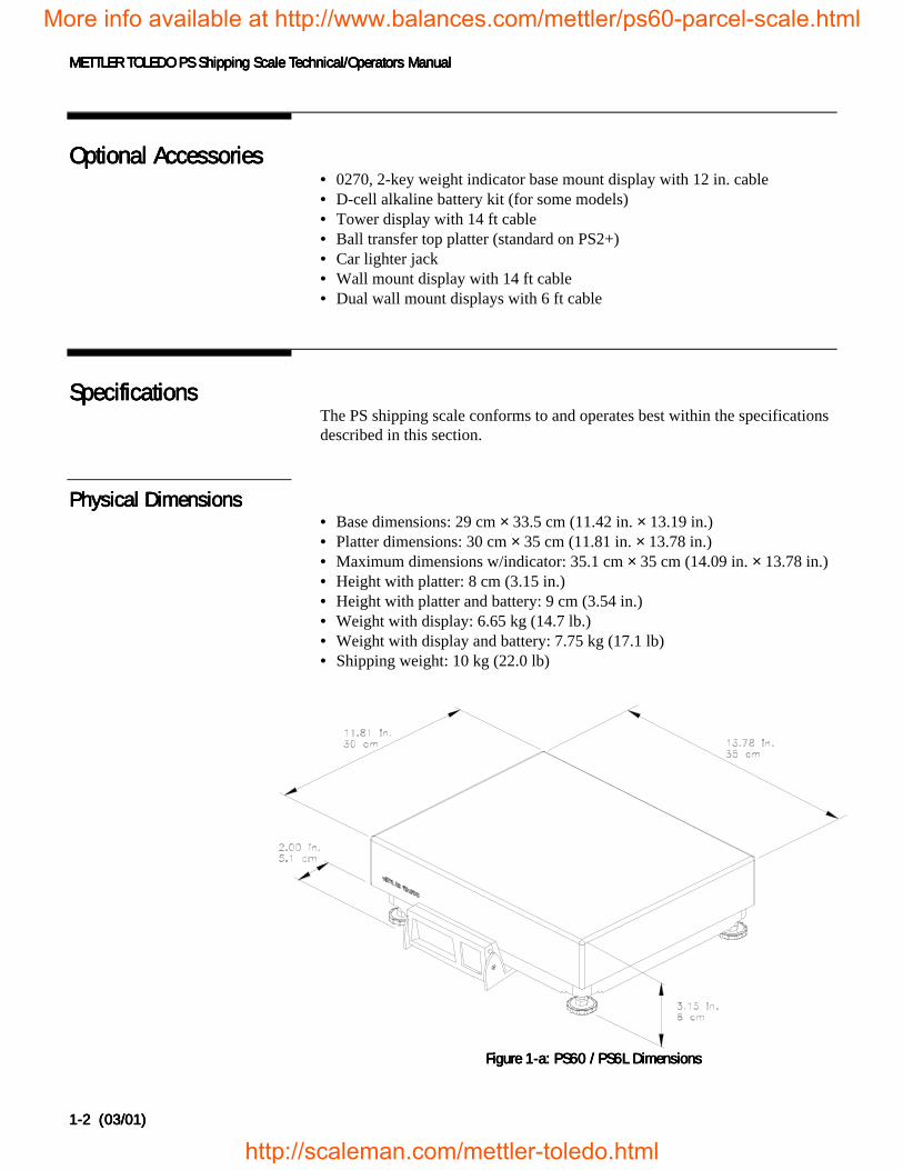
Physical DimensionsPhysical DimensionsPhysical DimensionsPhysical Dimensions• Base dimensions: 29 cm × 33.5 cm (11.42 in. × 13.19 in.)• Platter dimensions: 30 cm × 35 cm (11.81 in. × 13.78 in.)• Maximum dimensions w/indicator: 35.1 cm × 35 cm (14.09 in. × 13.78 in.)• Height with platter: 8 cm (3.15 in.)• Height with platter and battery: 9 cm (3.54 in.)• Weight with display: 6.65 kg (14.7 lb.)• Weight with display and battery: 7.75 kg (17.1 lb)• Shipping weight: 10 kg (22.0 lb)
Figure Figure Figure Figure 1111----aaaa: PS60 / PS6L Dimensions: PS60 / PS6L Dimensions: PS60 / PS6L Dimensions: PS60 / PS6L Dimensions
More info available at http://www.balances.com/mettler/ps60-parcel-scale.html
http://scaleman.com/mettler-toledo.html
Chapter 1: Chapter 1: Chapter 1: Chapter 1: IntroductionIntroductionIntroductionIntroductionSpecificationsSpecificationsSpecificationsSpecifications
(03/01) (03/01) (03/01) (03/01) 1-31-31-31-3
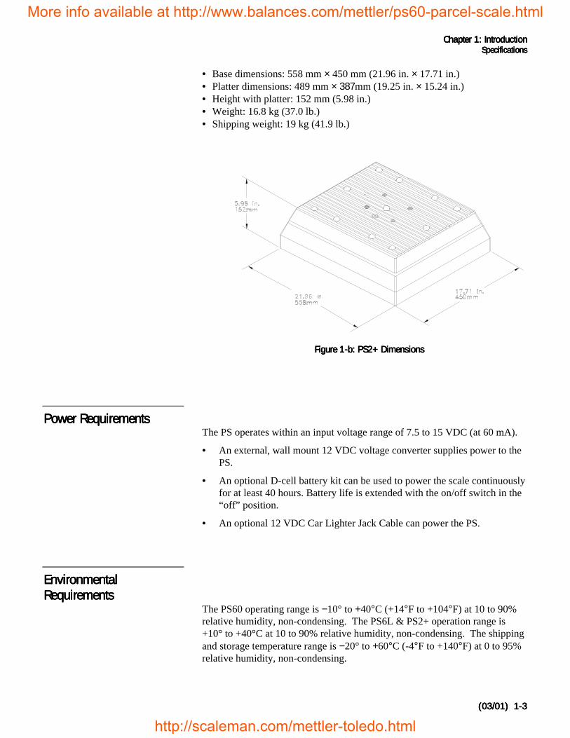
• Base dimensions: 558 mm × 450 mm (21.96 in. × 17.71 in.)• Platter dimensions: 489 mm × 387mm (19.25 in. × 15.24 in.)• Height with platter: 152 mm (5.98 in.)• Weight: 16.8 kg (37.0 lb.)• Shipping weight: 19 kg (41.9 lb.)
Figure Figure Figure Figure 1111-b: PS2+ Dimensions-b: PS2+ Dimensions-b: PS2+ Dimensions-b: PS2+ Dimensions
Power RequirementsPower RequirementsPower RequirementsPower RequirementsThe PS operates within an input voltage range of 7.5 to 15 VDC (at 60 mA).
• An external, wall mount 12 VDC voltage converter supplies power to thePS.
• An optional D-cell battery kit can be used to power the scale continuouslyfor at least 40 hours. Battery life is extended with the on/off switch in the“off” position.
• An optional 12 VDC Car Lighter Jack Cable can power the PS.
EnvironmentalEnvironmentalEnvironmentalEnvironmentalRequirementsRequirementsRequirementsRequirements
The PS60 operating range is −10° to +40°C (+14°F to +104°F) at 10 to 90%relative humidity, non-condensing. The PS6L & PS2+ operation range is+10° to +40°C at 10 to 90% relative humidity, non-condensing. The shippingand storage temperature range is −20° to +60°C (-4°F to +140°F) at 0 to 95%relative humidity, non-condensing.
More info available at http://www.balances.com/mettler/ps60-parcel-scale.html
http://scaleman.com/mettler-toledo.html
METTLER TOLEDO PS Shipping Scale Technical/Operators ManualMETTLER TOLEDO PS Shipping Scale Technical/Operators ManualMETTLER TOLEDO PS Shipping Scale Technical/Operators ManualMETTLER TOLEDO PS Shipping Scale Technical/Operators Manual
1-41-41-41-4 (03/01) (03/01) (03/01) (03/01)
The scale is designed for use in parcel shipping and other light industrialenvironments. This unit is not intended for wash-down or hazardous areaoperation, or for operation in environments of extreme dust, heat, cold, orhumidity.
Standards ComplianceStandards ComplianceStandards ComplianceStandards ComplianceThe PS60 meets or exceeds USA NIST HB-44, Australian NSC Document100, Canadian MC, European Community EN 45501, and OIML R76 for a3000 divison, Class III parcel scale. The Product also conforms to relevantCE product requirements.
The PS6L meets or exceeds USA NIST HB-44 requirements for a 4800division, Class III parcel scale.
Both the PS60 and PS6L have been tested and found to comply with the limitsfor a Class A computing device pursuant to Subpart J of Part 15 of FCCRules.
More info available at http://www.balances.com/mettler/ps60-parcel-scale.html
http://scaleman.com/mettler-toledo.html
Chapter 1: Chapter 1: Chapter 1: Chapter 1: IntroductionIntroductionIntroductionIntroductionStandards ComplianceStandards ComplianceStandards ComplianceStandards Compliance
(03/01) (03/01) (03/01) (03/01) 1-51-51-51-5
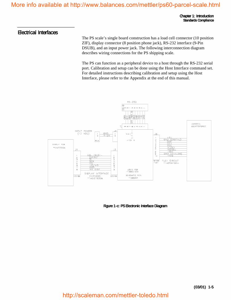
Electrical InterfacesElectrical InterfacesElectrical InterfacesElectrical InterfacesThe PS scale’s single board construction has a load cell connector (10 positionZIF), display connector (8 position phone jack), RS-232 interface (9-PinDSUB), and an input power jack. The following interconnection diagramdescribes wiring connections for the PS shipping scale.
The PS can function as a peripheral device to a host through the RS-232 serialport. Calibration and setup can be done using the Host Interface command set.For detailed instructions describing calibration and setup using the HostInterface, please refer to the Appendix at the end of this manual.
Figure Figure Figure Figure 1111-c: PS Electronic Interface Diagram-c: PS Electronic Interface Diagram-c: PS Electronic Interface Diagram-c: PS Electronic Interface Diagram
More info available at http://www.balances.com/mettler/ps60-parcel-scale.html
http://scaleman.com/mettler-toledo.html
Chapter 2Chapter 2Chapter 2Chapter 2: Installation and Calibration: Installation and Calibration: Installation and Calibration: Installation and CalibrationUnpacking and SetupUnpacking and SetupUnpacking and SetupUnpacking and Setup
(03/01) 2-(03/01) 2-(03/01) 2-(03/01) 2-1111
.
2222 Installation and CalibrationInstallation and CalibrationInstallation and CalibrationInstallation and CalibrationThis chapter gives detailed instructions and important information you willneed to install the PS successfully. Please read this chapter thoroughly beforeyou begin installation. This information is also covered in the PS OperatorInstructions.
Unpacking and SetupUnpacking and SetupUnpacking and SetupUnpacking and SetupPlease inspect the package as the carrier delivers it.
• If the shipping container is damaged, check for internal damage and file afreight claim with the carrier if necessary.
• If the container is undamaged, open the box, remove the scale, and place iton a solid, flat surface.
Please keep the packing material and shipping insert in case the scale needs tobe returned to METTLER TOLEDO. The PS is a precision instrument andmay be permanently damaged if not shipped in factory-approved packaging.
Typical package contents for the PS include:
• PS Shipping Scale• Installation Instructions• Power Supply• Optional Accessories
InstallationInstallationInstallationInstallationThe PS shipping scale is fully assembled at the factory, and you should nothave to assemble the unit. To install components other than those installed atthe factory, please refer to Chapter 5 Service and Maintenance.
1.1.1.1. Locate a suitable environment for the scale. Refer to Chapter 1 forenvironmental specifications.
2.2.2.2. Remove the packaging material from each side of the scale. Remove thescale by grasping the bottom sides of the scale. Do not lift the scale bygrasping the sub-platter.
3.3.3.3. Place the scale on a sturdy, level surface and remove any protectiveshipping materials under the platter.
If you choose to dispose of thepackage, please recycle thematerials.
The proper environment enhances theoperation and longevity of the scale.
More info available at http://www.balances.com/mettler/ps60-parcel-scale.html
http://scaleman.com/mettler-toledo.html
METTLER TOLEDO PS Shipping Scale Technical/Operators ManualMETTLER TOLEDO PS Shipping Scale Technical/Operators ManualMETTLER TOLEDO PS Shipping Scale Technical/Operators ManualMETTLER TOLEDO PS Shipping Scale Technical/Operators Manual
(03/01) 2-(03/01) 2-(03/01) 2-(03/01) 2-2222
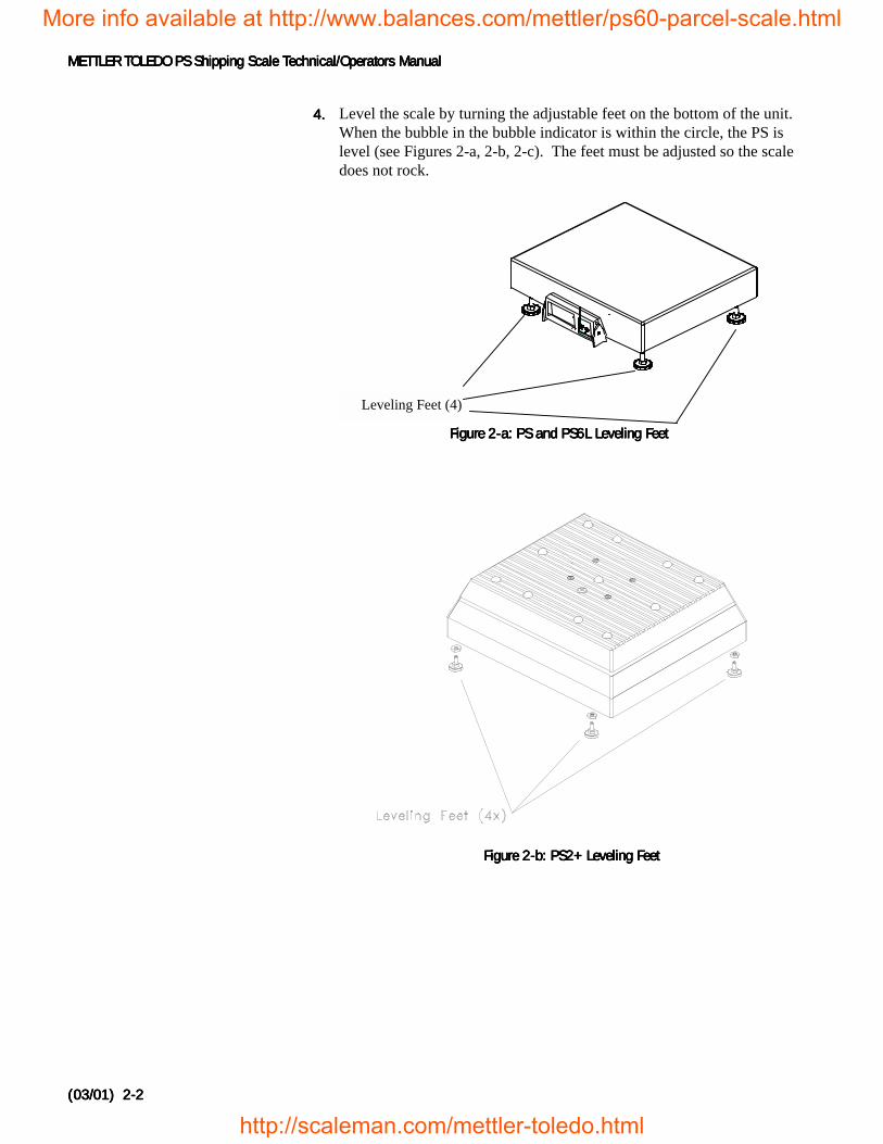
4.4.4.4. Level the scale by turning the adjustable feet on the bottom of the unit. When the bubble in the bubble indicator is within the circle, the PS islevel (see Figures 2-a, 2-b, 2-c). The feet must be adjusted so the scaledoes not rock.
Figure 2-b: PS2+ Leveling FeetFigure 2-b: PS2+ Leveling FeetFigure 2-b: PS2+ Leveling FeetFigure 2-b: PS2+ Leveling Feet
METTLER
TOLEDO
UNITS
ON/OFF
VV
-O-
Leveling Feet (4)
Figure 2-Figure 2-Figure 2-Figure 2-aaaa: PS and PS6L Leveling Feet: PS and PS6L Leveling Feet: PS and PS6L Leveling Feet: PS and PS6L Leveling Feet
More info available at http://www.balances.com/mettler/ps60-parcel-scale.html
http://scaleman.com/mettler-toledo.html
Chapter 2Chapter 2Chapter 2Chapter 2: Installation and Calibration: Installation and Calibration: Installation and Calibration: Installation and CalibrationUnpacking and SetupUnpacking and SetupUnpacking and SetupUnpacking and Setup
(03/01) 2-(03/01) 2-(03/01) 2-(03/01) 2-3333
IncorrectBubble is notwithin circle
CorrectBubble is
within circle
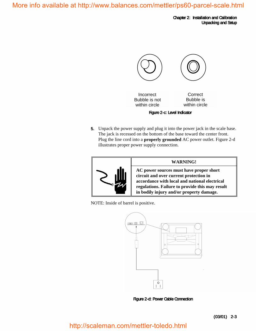
5.5.5.5. Unpack the power supply and plug it into the power jack in the scale base.The jack is recessed on the bottom of the base toward the center front.Plug the line cord into a properly grounded AC power outlet. Figure 2-dillustrates proper power supply connection.
WARNING!
AC power sources must have proper shortcircuit and over current protection inaccordance with local and national electricalregulations. Failure to provide this may resultin bodily injury and/or property damage.
NOTE: Inside of barrel is positive.
Figure 2-c: Level IndicatorFigure 2-c: Level IndicatorFigure 2-c: Level IndicatorFigure 2-c: Level Indicator
Figure 2-d: Power Cable ConnectionFigure 2-d: Power Cable ConnectionFigure 2-d: Power Cable ConnectionFigure 2-d: Power Cable Connection
More info available at http://www.balances.com/mettler/ps60-parcel-scale.html
http://scaleman.com/mettler-toledo.html
METTLER TOLEDO PS Shipping Scale Technical/Operators ManualMETTLER TOLEDO PS Shipping Scale Technical/Operators ManualMETTLER TOLEDO PS Shipping Scale Technical/Operators ManualMETTLER TOLEDO PS Shipping Scale Technical/Operators Manual
(03/01) 2-(03/01) 2-(03/01) 2-(03/01) 2-4444
Basic InformationBasic InformationBasic InformationBasic InformationThe following sections describe some basic information that you will need toknow as you install, calibrate, and use the PS in normal operating mode.
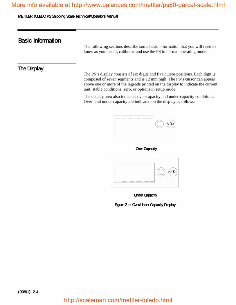
The DisplayThe DisplayThe DisplayThe DisplayThe PS’s display consists of six digits and five cursor positions. Each digit iscomposed of seven segments and is 12 mm high. The PS’s cursor can appearabove one or more of the legends printed on the display to indicate the currentunit, stable conditions, zero, or options in setup mode.
The display area also indicates over-capacity and under-capacity conditions.Over- and under-capacity are indicated on the display as follows:
0><
Over CapacityOver CapacityOver CapacityOver Capacity
0><
Figure 2-e: Over/Under Capacity DisplayFigure 2-e: Over/Under Capacity DisplayFigure 2-e: Over/Under Capacity DisplayFigure 2-e: Over/Under Capacity Display
Under CapacityUnder CapacityUnder CapacityUnder Capacity
More info available at http://www.balances.com/mettler/ps60-parcel-scale.html
http://scaleman.com/mettler-toledo.html
Chapter 2Chapter 2Chapter 2Chapter 2: Installation and Calibration: Installation and Calibration: Installation and Calibration: Installation and CalibrationInitial Calibration using GeoCalInitial Calibration using GeoCalInitial Calibration using GeoCalInitial Calibration using GeoCal
(03/01) 2-(03/01) 2-(03/01) 2-(03/01) 2-5555
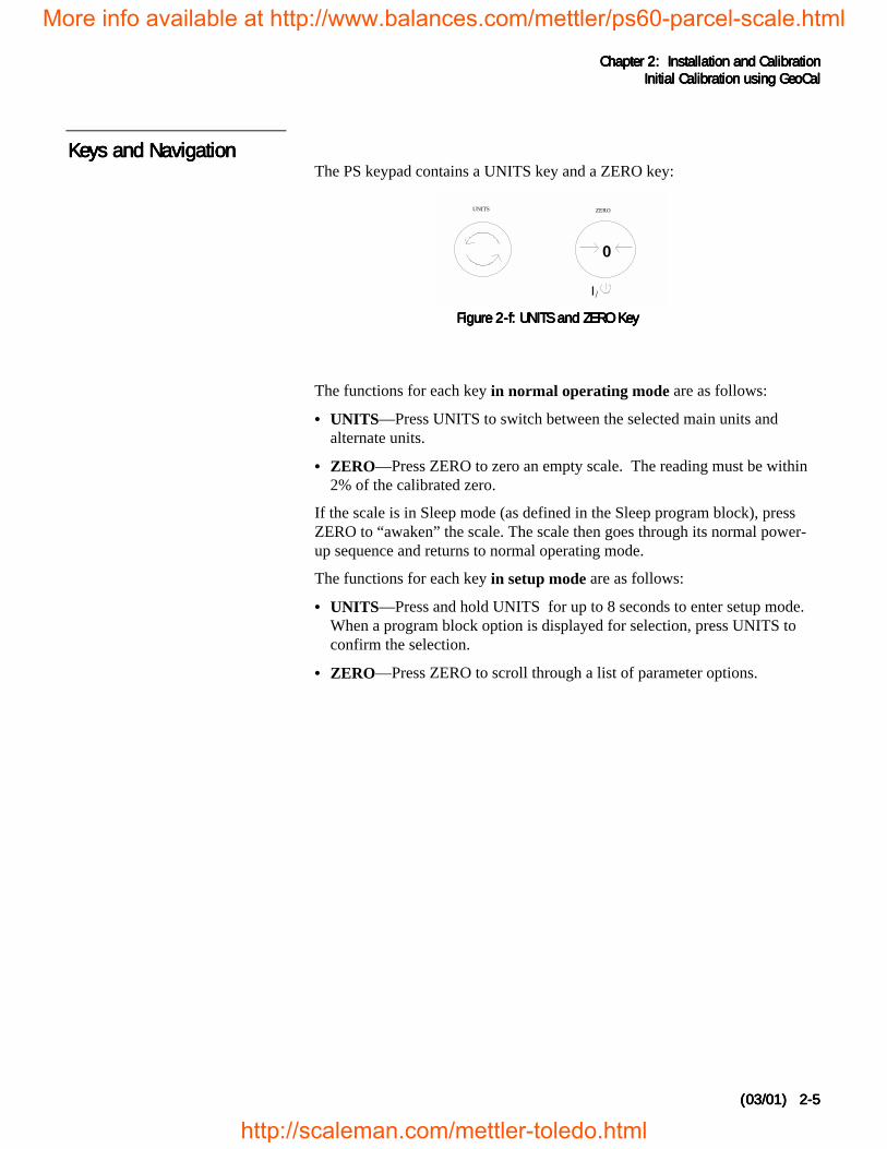
Keys and NavigationKeys and NavigationKeys and NavigationKeys and NavigationThe PS keypad contains a UNITS key and a ZERO key:
The functions for each key in normal operating mode are as follows:
• UNITS—Press UNITS to switch between the selected main units andalternate units.
• ZERO—Press ZERO to zero an empty scale. The reading must be within2% of the calibrated zero.
If the scale is in Sleep mode (as defined in the Sleep program block), pressZERO to “awaken” the scale. The scale then goes through its normal power-up sequence and returns to normal operating mode.
The functions for each key in setup mode are as follows:
• UNITS—Press and hold UNITS for up to 8 seconds to enter setup mode.When a program block option is displayed for selection, press UNITS toconfirm the selection.
• ZERO—Press ZERO to scroll through a list of parameter options.
I/
0
UNITS ZERO
Figure 2-f: UNITS and ZERO Key Figure 2-f: UNITS and ZERO Key Figure 2-f: UNITS and ZERO Key Figure 2-f: UNITS and ZERO Key
More info available at http://www.balances.com/mettler/ps60-parcel-scale.html
http://scaleman.com/mettler-toledo.html
METTLER TOLEDO PS Shipping Scale Technical/Operators ManualMETTLER TOLEDO PS Shipping Scale Technical/Operators ManualMETTLER TOLEDO PS Shipping Scale Technical/Operators ManualMETTLER TOLEDO PS Shipping Scale Technical/Operators Manual
(03/01) 2-(03/01) 2-(03/01) 2-(03/01) 2-6666
Initial CalibrationInitial CalibrationInitial CalibrationInitial Calibrationusing using using using GEOCAL™GEOCAL™GEOCAL™GEOCAL™
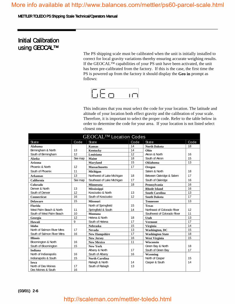
The PS shipping scale must be calibrated when the unit is initially installed tocorrect for local gravity variations thereby ensuring accurate weighing results.If the GEOCAL™ capabilities of your PS unit have been activated, the unithas been pre-calibrated from the factory. If this is the case, the first time thePS is powered up from the factory it should display the Geo in prompt asfollows:
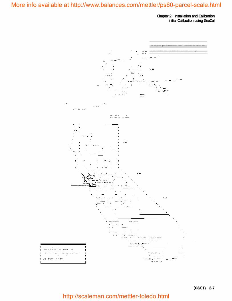
This indicates that you must select the code for your location. The latitude andaltitude of your location both effect gravity and the calibration of your scale.Therefore, it is important to select the proper code. Refer to the table below inorder to determine the code for your area. If your location is not listed selectclosest one.
GEOCAL™ Location CodesState Code State Code State CodeAlabama Kansas 14 North Dakota 18Birmingham & North 13 Kentucky 14 OhioSouth of Birmingham 12 Louisiana 12 Akron & North 16Alaska See map Maine 18 South of Akron 15Arizona Maryland 15 Oklahoma 13Phoenix & North 12 Massachusetts 17 OregonSouth of Phoenix 11 Michigan Salem & North 18
Arkansas 13 Northwest of Lake Michigan 18 Between Oakridge & Salem 17
California See map Southeast of Lake Michigan 17 South of Oakridge 16
Colorado Minnesota 18 Pennsylvania 16Denver & North 13 Mississippi Rhode Island 16South of Denver 12 Kosciusko & North 13 South Carolina 13Connecticut 16 South of Kosciusko 12 South Dakota 17
Delaware 15 Missouri Tennessee 13
Florida North of Springfield 15 TexasWest Palm Beach & North 11 Springfield & South 14 Northeast of Colorado River 12South of West Palm Beach 10 Montana Southwest of Colorado River 11Georgia 12 Helena & North 18 Utah 13Hawaii 9 South of Helena 17 Vermont 17Idaho Nebraska 15 Virginia 14North of Salmon River Mtns 17 Nevada 13 Washington, DC 15South of Salmon River Mtns 16 New Hampshire 17 Washington State 18Illinois New Jersey 16 West Virginia 15Bloomington & North 16 New Mexico 11 WisconsinSouth of Bloomington 15 New York Green Bay & North 18Indiana Albany & North 17 South of Green Bay 17North of Indianapolis 16 South of Albany 16 WyomingIndianapolis & South 15 North Carolina North of Casper 15Iowa Raliegh & North 14 Casper & South 14North of Des Moines 17 South of Raliegh 13Des Moines & South 16
More info available at http://www.balances.com/mettler/ps60-parcel-scale.html
http://scaleman.com/mettler-toledo.html
Chapter 2Chapter 2Chapter 2Chapter 2: Installation and Calibration: Installation and Calibration: Installation and Calibration: Installation and CalibrationInitial Calibration using GeoCalInitial Calibration using GeoCalInitial Calibration using GeoCalInitial Calibration using GeoCal
(03/01) 2-(03/01) 2-(03/01) 2-(03/01) 2-7777
More info available at http://www.balances.com/mettler/ps60-parcel-scale.html
http://scaleman.com/mettler-toledo.html
METTLER TOLEDO PS Shipping Scale Technical/Operators ManualMETTLER TOLEDO PS Shipping Scale Technical/Operators ManualMETTLER TOLEDO PS Shipping Scale Technical/Operators ManualMETTLER TOLEDO PS Shipping Scale Technical/Operators Manual
(03/01) 2-(03/01) 2-(03/01) 2-(03/01) 2-8888
The sequence for selecting your GEOCAL™ code is as follows:
1.1.1.1. Press the ZERO key to display the first code option and continue pressingit to scroll through all of the available codes.
2.2.2.2. Press the UNITS key to select the code for your location. The display willthen prompt done. Press the UNITS key again to restart the scale.
Power-up SequencePower-up SequencePower-up SequencePower-up SequenceThe PS goes through a power-up sequence each time power is applied or thescale is brought from its power-down ("sleep") state. The scale performs adiagnostic test on its ROM and RAM, then proceeds to normal operatingmode. The power-up sequence is as follows:
1.1.1.1. All segments of the display characters are activated. This verifiesoperation of all segments.
2.2.2.2. The scale displays the software part number followed by the softwarerevision status.
3.3.3.3. The scale then captures zero (if the zero reading is within ± 10%calibrated capacity on power-up) and is ready for normal operation.
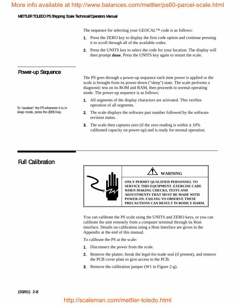
Full CalibrationFull CalibrationFull CalibrationFull Calibration
WARNING
ONLY PERMIT QUALIFIED PERSONNEL TOSERVICE THIS EQUIPMENT. EXERCISE CAREWHEN MAKING CHECKS, TESTS ANDADJUSTMENTS THAT MUST BE MADE WITHPOWER ON. FAILING TO OBSERVE THESEPRECAUTIONS CAN RESULT IN BODILY HARM.
You can calibrate the PS scale using the UNITS and ZERO keys, or you cancalibrate the unit remotely from a computer terminal through its Hostinterface. Details on calibration using a Host Interface are given in theAppendix at the end of this manual.
To calibrate the PS at the scale:
1.1.1.1. Disconnect the power from the scale.
2.2.2.2. Remove the platter, break the legal-for-trade seal (if present), and removethe PCB cover plate to give access to the PCB.
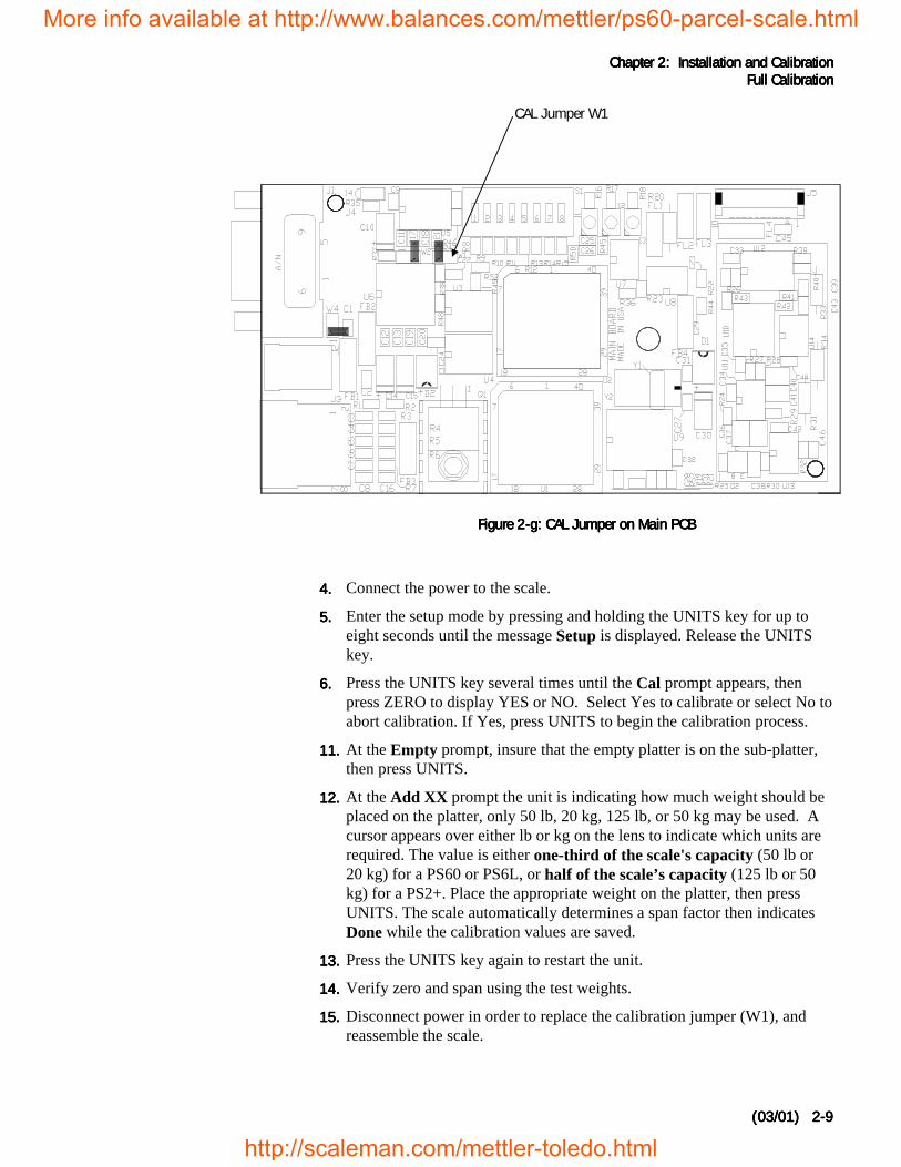
3.3.3.3. Remove the calibration jumper (W1 in Figure 2-g).
To “awaken” the PS whenever it is insleep mode, press the ZERO key.
More info available at http://www.balances.com/mettler/ps60-parcel-scale.html
http://scaleman.com/mettler-toledo.html
Chapter 2Chapter 2Chapter 2Chapter 2: Installation and Calibration: Installation and Calibration: Installation and Calibration: Installation and CalibrationFull CalibrationFull CalibrationFull CalibrationFull Calibration
(03/01) 2-(03/01) 2-(03/01) 2-(03/01) 2-9999
4.4.4.4. Connect the power to the scale.
5.5.5.5. Enter the setup mode by pressing and holding the UNITS key for up toeight seconds until the message Setup is displayed. Release the UNITSkey.
6.6.6.6. Press the UNITS key several times until the Cal prompt appears, thenpress ZERO to display YES or NO. Select Yes to calibrate or select No toabort calibration. If Yes, press UNITS to begin the calibration process.
11.11.11.11. At the Empty prompt, insure that the empty platter is on the sub-platter,then press UNITS.
12.12.12.12. At the Add XX prompt the unit is indicating how much weight should beplaced on the platter, only 50 lb, 20 kg, 125 lb, or 50 kg may be used. Acursor appears over either lb or kg on the lens to indicate which units arerequired. The value is either one-third of the scale's capacity (50 lb or20 kg) for a PS60 or PS6L, or half of the scale’s capacity (125 lb or 50kg) for a PS2+. Place the appropriate weight on the platter, then pressUNITS. The scale automatically determines a span factor then indicatesDone while the calibration values are saved.
13.13.13.13. Press the UNITS key again to restart the unit.
14.14.14.14. Verify zero and span using the test weights.
15.15.15.15. Disconnect power in order to replace the calibration jumper (W1), andreassemble the scale.
Figure 2-g: CAL Jumper on Main PCBFigure 2-g: CAL Jumper on Main PCBFigure 2-g: CAL Jumper on Main PCBFigure 2-g: CAL Jumper on Main PCB
CAL Jumper W1
More info available at http://www.balances.com/mettler/ps60-parcel-scale.html
http://scaleman.com/mettler-toledo.html
METTLER TOLEDO PS Shipping Scale Technical/Operators ManualMETTLER TOLEDO PS Shipping Scale Technical/Operators ManualMETTLER TOLEDO PS Shipping Scale Technical/Operators ManualMETTLER TOLEDO PS Shipping Scale Technical/Operators Manual
(03/01) 2-(03/01) 2-(03/01) 2-(03/01) 2-10101010
The PS is now calibrated and ready to configure to your needs. Chapter 3 ofthis manual gives setup and configuration details.
Metrological SealMetrological SealMetrological SealMetrological SealInstallationInstallationInstallationInstallation
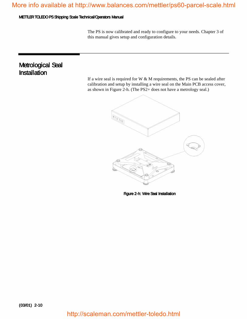
If a wire seal is required for W & M requirements, the PS can be sealed aftercalibration and setup by installing a wire seal on the Main PCB access cover,as shown in Figure 2-h. (The PS2+ does not have a metrology seal.)
Figure 2-h: Wire Seal InstallationFigure 2-h: Wire Seal InstallationFigure 2-h: Wire Seal InstallationFigure 2-h: Wire Seal Installation
More info available at http://www.balances.com/mettler/ps60-parcel-scale.html
http://scaleman.com/mettler-toledo.html
Chapter 3: Configuring the Setup ParametersChapter 3: Configuring the Setup ParametersChapter 3: Configuring the Setup ParametersChapter 3: Configuring the Setup ParametersConfiguring Setup ParametersConfiguring Setup ParametersConfiguring Setup ParametersConfiguring Setup Parameters
(03/01) 3-(03/01) 3-(03/01) 3-(03/01) 3-1111
3333 Configuring the Setup ParametersConfiguring the Setup ParametersConfiguring the Setup ParametersConfiguring the Setup ParametersThis chapter discusses basic information related to PS configuration andspecific instructions on configuring each program block and operatingparameter.
Basic SetupBasic SetupBasic SetupBasic SetupInformationInformationInformationInformation
The following sections describe some basic information that you will need toknow as you configure the setup parameters for the PS.
Program Block AccessProgram Block AccessProgram Block AccessProgram Block AccessThe PS’s operational parameters are configured in setup mode through aseries of program blocks. The program blocks are accessed as follows:
1.1.1.1. Press and hold the UNITS key for up to eight seconds until the messageSetup? is displayed. Release the UNITS key. When released, the PSdisplays either the Pb 0 or Alt prompt indicating the first program block.
Exit SetupExit SetupExit SetupExit SetupExit setup mode as follows:
1.1.1.1. Press UNITS to display the End prompt.
2.2.2.2. Press ZERO to display the desired exit option. Exit options include:
• No—Do not exit setup mode at this time.
• Save—Save all changes program block parameters then exit setupmode.
• Abort—Exit setup mode but do not save any changes made in thissession.
• Various Defaults—Reset all program block parameters to a pre-specified set of values, then exit setup mode. For details, refer to theEnd Program Block section.
3.3.3.3. Press UNITS to carry out the displayed option. The PS automatically exitssetup mode and returns to normal operating mode unless No is selected.
There are two alternate ways to exit the setup mode:
More info available at http://www.balances.com/mettler/ps60-parcel-scale.html
http://scaleman.com/mettler-toledo.html
METTLER TOLEDO PS Shipping Scale Technical/Operators ManualMETTLER TOLEDO PS Shipping Scale Technical/Operators ManualMETTLER TOLEDO PS Shipping Scale Technical/Operators ManualMETTLER TOLEDO PS Shipping Scale Technical/Operators Manual
(03/01) 3-(03/01) 3-(03/01) 3-(03/01) 3-2222
• The scale automatically leaves the setup mode after it has beencalibrated.
• Disconnect the power from the scale. Changes will not be saved.
Configuring SetupConfiguring SetupConfiguring SetupConfiguring SetupParametersParametersParametersParameters
This section describes the program blocks that govern normal operationincluding:
• Push Button Zero * • ASCII• Zero Cursor * • Parity• Power-up Units * • Stop Bits• Build * • Protocol• Alternate Units • Sleep• Mode * • GEOCAL™*• Filter • Calibration *• Baud • End
This is the order that they appear in the prompts.
* The Push Button Zero, Zero Cursor, Power-up Units, Capacity/Increment(Build), Display Mode, GEOCAL™ Activation, and Calibrate program blocksare hidden in setup mode when the Metrology PCB jumper (W1) is in place.These program blocks are used only when the jumper is removed and thescale is being calibrated. Please refer to Chapter 2 for calibration details.
The PS can also be configured remotely through the METTLER TOLEDOHost Interface. Details for configuring the scale using the Host Interface aregiven in the Appendix at the end of this manual.
To configure the PS at the scale, enter the setup mode by pressing and holdingthe UNITS key for up to eight seconds until the message Setup is displayed.Release the UNITS key, then configure the PS program block parameters.
Push Button ZeroPush Button ZeroPush Button ZeroPush Button ZeroProgram BlockProgram BlockProgram BlockProgram Block
The Push Button Zero program block lets you configure the range withinwhich the PS can capture zero. The only push button zero capture rangecurrently supported is ± 2%. (Metrology PCB jumper must be removed.)
To configure the program block:
1.1.1.1. Press UNITS to display the Pb 0 prompt, then press ZERO.
2.2.2.2. Press UNITS again to accept the 2 pct option. The PS continues to theZero Cursor program block.
More info available at http://www.balances.com/mettler/ps60-parcel-scale.html
http://scaleman.com/mettler-toledo.html
Chapter 3: Configuring the Setup ParametersChapter 3: Configuring the Setup ParametersChapter 3: Configuring the Setup ParametersChapter 3: Configuring the Setup ParametersConfiguring Setup ParametersConfiguring Setup ParametersConfiguring Setup ParametersConfiguring Setup Parameters
(03/01) 3-(03/01) 3-(03/01) 3-(03/01) 3-3333
Zero Cursor ProgramZero Cursor ProgramZero Cursor ProgramZero Cursor ProgramBlockBlockBlockBlock
The Zero Cursor program block lets you enable or disable the center of zeroindicator on the PS. (Metrology PCB jumper must be removed.)
To configure the program block:
1.1.1.1. Press UNITS to display the 0 CurS prompt, then press ZERO.
2.2.2.2. Press ZERO to display the desired approval setting, enable or disable.
3.3.3.3. Press UNITS to accept the displayed option. The PS continues to thePower-up Unit program block.
Power-up Unit ProgramPower-up Unit ProgramPower-up Unit ProgramPower-up Unit ProgramBlockBlockBlockBlock
The Power up Unit program block lets you select which units will be active onthe PS upon startup. This program block will effect the build options that areseen in the Build program block.
To configure the program block:
1.1.1.1. Press UNITS to display the unitS prompt, then press ZERO.
2.2.2.2. Press ZERO to display the desired approval setting, pounds or metric.
3.3.3.3. Press UNITS to accept the displayed option. The PS continues to theBuild / Alternate Units program block.
Build Program BlockBuild Program BlockBuild Program BlockBuild Program BlockThe build program block lets you chose a capacity and increment size settingfor the product based on the model you have purchased and the power-upunits selection. (Metrology PCB jumper must be removed.)
To configure the program block:
1.1.1.1. Press UNITS to display the buiLd prompt, then press ZERO.
2.2.2.2. Press ZERO to display the desired approval setting. Option may vary asfollows:
Standard PS60, 3000dPower-up units = Pounds Power-up units = Metric150-02 150 x 0.02 lb. 60-01 60 x 0.01 kg150-05 150 x 0.05 lb. * 60-02 60 x 0.02 kg100-02 100 x 0.02 lb. 50-01 50 x 0.01 kg
70-ni 0-50 x 0.01 kg, 50-70 x 0.05 kg
More info available at http://www.balances.com/mettler/ps60-parcel-scale.html
http://scaleman.com/mettler-toledo.html
METTLER TOLEDO PS Shipping Scale Technical/Operators ManualMETTLER TOLEDO PS Shipping Scale Technical/Operators ManualMETTLER TOLEDO PS Shipping Scale Technical/Operators ManualMETTLER TOLEDO PS Shipping Scale Technical/Operators Manual
(03/01) 3-(03/01) 3-(03/01) 3-(03/01) 3-4444
Multi-interval PS60, 2x3000dPower-up units = Pounds Power-up units = Metric150-02 150 x 0.02 lb. 60-01 60 x 0.01 kg150-05 150 x 0.05 lb. 60-02 60 x 0.02 kg100-02 100 x 0.02 lb. 50-01 50 x 0.01 kg150-ni 0-60 x 0.02 lb., 60-150 x 0.05 lb. * 60-ni 0-30 x 0.01 kg, 30-60 x 0.02 kg
70-ni 0-50 x 0.01 kg, 50-70 x 0.05 kg
PS6LPower-up units = Pounds149-ni 0-10 lb. x 0.1 oz, 10-70 lb. x 0.2 oz, 70-150 lb. x 0.5 oz *150-n5 0-5 x 0.005 lb., 5-25 x 0.05, 25-150 x 0.1 lb.
PS2+Power-up units = Pounds Power-up units = Metric250-1 250 x 0.1 lb. * 100-05 100 x 0.05 kg
* Default for that model.
‘ni’ on the display represents Multi-Interval‘n5’ on the display represents Multi-Interval with 0.005 lb. increment size
3.3.3.3. Press UNITS to accept the displayed option. The PS continues to theAlternate Units program block.
Note: the scale can only be sealed in the build that is listed on the data label.
Alternate Units ProgramAlternate Units ProgramAlternate Units ProgramAlternate Units ProgramBlockBlockBlockBlock
This program block lets you enable or disable unit switching during normaloperation.
To configure the program block:
1.1.1.1. Press UNITS to display the ALt prompt, then press ZERO.
2.2.2.2. Press ZERO to display the desired approval setting, enable or disable.
3.3.3.3. Press UNITS to accept the displayed option. The PS continues to theMode / Filter program block.
Mode Program BlockMode Program BlockMode Program BlockMode Program BlockThe Mode program block lets you configure which mode is used to displayweight. (Metrology PCB jumper must be removed.)
To configure the program block:
1.1.1.1. Press UNITS to display the nodE prompt, then press ZERO.
2.2.2.2. Press ZERO to display the desired mode. Options include:
More info available at http://www.balances.com/mettler/ps60-parcel-scale.html
http://scaleman.com/mettler-toledo.html
Chapter 3: Configuring the Setup ParametersChapter 3: Configuring the Setup ParametersChapter 3: Configuring the Setup ParametersChapter 3: Configuring the Setup ParametersConfiguring Setup ParametersConfiguring Setup ParametersConfiguring Setup ParametersConfiguring Setup Parameters
(03/01) 3-(03/01) 3-(03/01) 3-(03/01) 3-5555
• Normal• Expanded – typically x10• Classifier – weight classifier rounding
3.3.3.3. Press UNITS to accept the displayed mode option. The PS continues tothe Filter program block.
Filter Program BlockFilter Program BlockFilter Program BlockFilter Program BlockThe Filter program block lets you configure the noise filter that is used indetermining weight stability on the scale. The PS disregards environmentalnoise such as vibrations that affect the weighing accuracy according to thefilter setting.
To configure the program block:
1.1.1.1. Press UNITS to display the FiLtEr prompt, then press ZERO.
2.2.2.2. Press ZERO to display the desired noise filter. Options include:
• Light• Heavy• Medium
3.3.3.3. Press UNITS to accept the displayed filter option. The PS continues to theBaud program block.
Baud Program BlockBaud Program BlockBaud Program BlockBaud Program BlockThis program block lets you set the baud rate (the speed at which data istransmitted in bits-per-second).
To configure the program block:
1.1.1.1. Press UNITS to display the bAud prompt, then press ZERO.
2.2.2.2. Press ZERO to display the desired baud rate. Options include:
• 300 • 4800• 1200 • 9600• 2400 • 19200
3.3.3.3. Press UNITS to accept the displayed baud rate option. The PS continuesto the ASCII program block.
ASCII Program BlockASCII Program BlockASCII Program BlockASCII Program BlockThe ASCII program block lets you select the number of bits that make up anASCII character. Most METTLER TOLEDO equipment communicates usingseven data bits.
To configure the program block:
1.1.1.1. Press UNITS to display the ASCii prompt, then press ZERO.
Settling time increases with heavierfilter setting.
More info available at http://www.balances.com/mettler/ps60-parcel-scale.html
http://scaleman.com/mettler-toledo.html
METTLER TOLEDO PS Shipping Scale Technical/Operators ManualMETTLER TOLEDO PS Shipping Scale Technical/Operators ManualMETTLER TOLEDO PS Shipping Scale Technical/Operators ManualMETTLER TOLEDO PS Shipping Scale Technical/Operators Manual
(03/01) 3-(03/01) 3-(03/01) 3-(03/01) 3-6666
2.2.2.2. Press ZERO to display the desired bit selection. Options include:
• Seven (7)• Eight (8)
3.3.3.3. Press UNITS to accept the displayed option. The PS continues to theParity program block.
Parity Program BlockParity Program BlockParity Program BlockParity Program BlockThe Parity program block lets you select the parity option for datatransmission. Parity is an error checking mechanism. To configure theprogram block:
1.1.1.1. Press UNITS to display the PAr prompt, then press ZERO.
2.2.2.2. Press ZERO to display the desired parity option. Options include:
• Space • Even• Mark • None• Odd
3.3.3.3. Press UNITS to accept the parity option. The PS continues to the Stopprogram block.
Note: options will depend on the ASCII bits selection.
Stop Program BlockStop Program BlockStop Program BlockStop Program BlockThe Stop program block lets you select the number of stop bits to betransmitted for each ASCII character. Most METTLER TOLEDO productswill work with either 1 or 2 stop bits.
To configure the program block:
1.1.1.1. Press UNITS to display the StoP prompt, then press ZERO.
2.2.2.2. Press ZERO to display 1 or 2 stop bits, then press UNITS to accept thedisplayed selection. The PS continues to the Protocol program block.
Protocol Program BlockProtocol Program BlockProtocol Program BlockProtocol Program BlockThe Protocol program block lets you select a pre-configured set of scalecommands. Protocols are configured in the factory according to your orderinginformation. This section gives instructions on how to select a protocol only.
To select a protocol:
1.1.1.1. Press UNITS to display the Proto prompt, then press ZERO.
2.2.2.2. Press ZERO to display the desired protocol. Options include:
• Toledo (MT command set) • Proto 4 (UPS command set)• Proto 1 (Fed Ex command set) • Proto 5 (Purolator command set)
Toledo protocol contained in thePS is identical to the Toledoprotocol within the industrial buildsof the 8213. The PS replaces theindustrial versions of the 8213.
More info available at http://www.balances.com/mettler/ps60-parcel-scale.html
http://scaleman.com/mettler-toledo.html
Chapter 3: Configuring the Setup ParametersChapter 3: Configuring the Setup ParametersChapter 3: Configuring the Setup ParametersChapter 3: Configuring the Setup ParametersConfiguring Setup ParametersConfiguring Setup ParametersConfiguring Setup ParametersConfiguring Setup Parameters
(03/01) 3-(03/01) 3-(03/01) 3-(03/01) 3-7777
• Proto 2 (Weightronix SC-320 com. set) • Proto 6 (Airbornecommand set)
• Proto 3 (Weightronix 3870 com. set) • Disable(turns off communications)
3.3.3.3. Press UNITS to accept the protocol option. The PS continues to the Sleepprogram block.
Note: Protocols 1-6 are not available on the PS6L.
Sleep Program BlockSleep Program BlockSleep Program BlockSleep Program BlockThe Sleep program block lets you configure the sleep timer. Powerconsumption is reduced by approximately 60% while in Sleep mode. IMPORTANT: For battery powered units, it is important to turn batterypower off (using the rocker switch underneath the scale) when the scale isnot in use.
To configure the Sleep program block:
1.1.1.1. Press UNITS to display the SLEEP prompt, then press ZERO.
2.2.2.2. Press ZERO to display the desired sleep timer option. Options include:
• Disable—the PS will not power-down regardless of time betweentransactions (inactivity)
• 5 min—the PS will enter Sleep mode after 5 minutes with no activity
3.3.3.3. Press UNITS to accept the sleep timer option. The PS continues to theGEOCAL™ / End program block.
GeoCal Program BlockGeoCal Program BlockGeoCal Program BlockGeoCal Program BlockThis program block lets you enable the GEOCAL™ prompt at power-up. Ifthis setting is enabled, the unit will prompt for the entry of a GEOCAL™code after setup is exited.
To configure the program block:
1.1.1.1. Press UNITS to display the GEo in prompt, then press ZERO.
2.2.2.2. Press ZERO to display the desired approval setting, enable or disable.
3.3.3.3. Press UNITS to accept the displayed option. The PS continues to the Calprogram block.
Calibration ProgramCalibration ProgramCalibration ProgramCalibration ProgramBlockBlockBlockBlock
See Chapter 2 for detailed information about activating GEOCAL™ andcalibrating the PS. (Metrology PCB jumper must be removed.)
Power is saved if RS-232 interface isnot used.
In normal operating mode the scaleis powered-up by pressing the ZERO(ON/OFF) key.
More info available at http://www.balances.com/mettler/ps60-parcel-scale.html
http://scaleman.com/mettler-toledo.html
METTLER TOLEDO PS Shipping Scale Technical/Operators ManualMETTLER TOLEDO PS Shipping Scale Technical/Operators ManualMETTLER TOLEDO PS Shipping Scale Technical/Operators ManualMETTLER TOLEDO PS Shipping Scale Technical/Operators Manual
(03/01) 3-(03/01) 3-(03/01) 3-(03/01) 3-8888
End Program BlockEnd Program BlockEnd Program BlockEnd Program BlockThe End program block lets you save the configuration and exit setup mode.This program block does not have parameters to configure.
To use the End program block:
1.1.1.1. Press UNITS to display the End prompt.
2.2.2.2. Press ZERO to display the desired exit option. Exit options include:
• Default—Reset all program block parameters to standard MT values,then exit setup mode.
• Abort—Exit setup mode but do not save any changes made in thissession.
• Save—Do not exit setup mode at this time. PS returns to the firstprogram block.
• Def x—Company specific.
If you are using software from one of the following carriers your PS scalecan be completely configured for use by selecting one of the optionsbelow (not available on PS6L):Carrier End prompt selection• RPS Default• DHL Default• Fed Ex Def 1• UPS Def 4• Purolator Def 5• Airborne Def 6
Choosing a default, rather the selecting SAVE, will automatically set thefollowing program blocks:
• Zero Cursor • PARITY• Power-up Units • STOP BITS• Units Switching • Sleep Mode• Filter • Protocol• BAUD • Display Mode• ASCII BIT String
The PS6L only has the Default option. This is the standard MTcommunications parameters and command set.If your carrier is not listed try the default option, otherwise contact yourcarrier.
3.3.3.3. Press UNITS to carry out the displayed option.
More info available at http://www.balances.com/mettler/ps60-parcel-scale.html
http://scaleman.com/mettler-toledo.html
Chapter 4: Chapter 4: Chapter 4: Chapter 4: Operating InstructionsOperating InstructionsOperating InstructionsOperating InstructionsKeypad and DisplayKeypad and DisplayKeypad and DisplayKeypad and Display
(03/01)(03/01)(03/01)(03/01) 4-14-14-14-1
4444 Operating InstructionsOperating InstructionsOperating InstructionsOperating InstructionsThis chapter gives information that an operator will need to become familiarwith the scale and perform its functions in normal operating mode. The scaleoperates based on the current program block configuration. Please refer toChapter 3 for more information on configuring the PS.
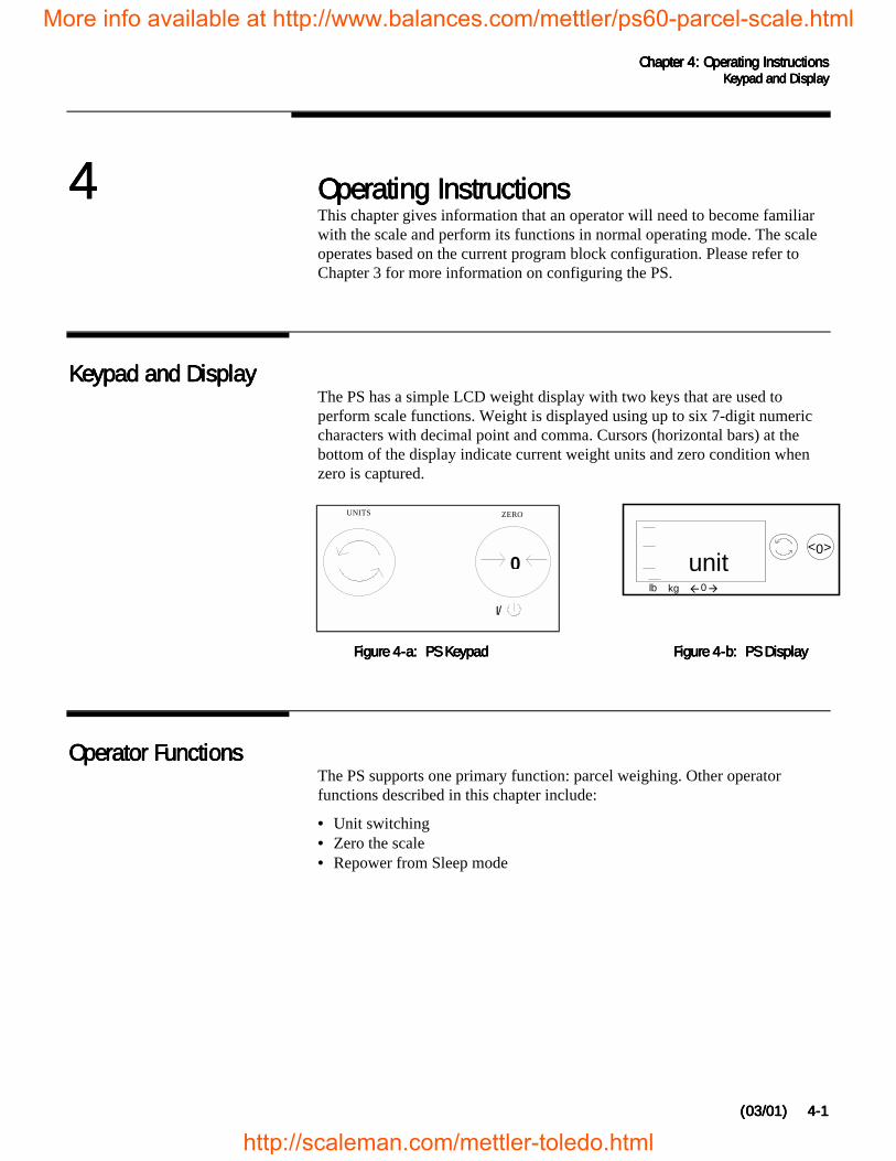
Keypad and DisplayKeypad and DisplayKeypad and DisplayKeypad and DisplayThe PS has a simple LCD weight display with two keys that are used toperform scale functions. Weight is displayed using up to six 7-digit numericcharacters with decimal point and comma. Cursors (horizontal bars) at thebottom of the display indicate current weight units and zero condition whenzero is captured.
Operator FunctionsOperator FunctionsOperator FunctionsOperator FunctionsThe PS supports one primary function: parcel weighing. Other operatorfunctions described in this chapter include:
• Unit switching• Zero the scale• Repower from Sleep mode
I/
0
UNITS ZERO
0><
unitlb kg !0"
Figure 4-a: PS KeypadFigure 4-a: PS KeypadFigure 4-a: PS KeypadFigure 4-a: PS Keypad Figure 4-b: PS DisplayFigure 4-b: PS DisplayFigure 4-b: PS DisplayFigure 4-b: PS Display
More info available at http://www.balances.com/mettler/ps60-parcel-scale.html
http://scaleman.com/mettler-toledo.html
METTLER TOLEDO PS Shipping Scale Technical/Operators ManualMETTLER TOLEDO PS Shipping Scale Technical/Operators ManualMETTLER TOLEDO PS Shipping Scale Technical/Operators ManualMETTLER TOLEDO PS Shipping Scale Technical/Operators Manual
(03/01)(03/01)(03/01)(03/01)4-24-24-24-2
Parcel WeighingParcel WeighingParcel WeighingParcel WeighingBefore weighing parcels on the PS, please be sure the scale is configured asdesired (Chapter 3) and power is applied as instructed in Chapter 2 of thismanual.
To weigh a package:
1.1.1.1. Press ZERO to capture zero. The display reads 0.00 and a cursor appearsabove the zero indicator in the legend.
2.2.2.2. Place the parcel to be weighed on the platter. The display reads the parcelweight with a cursor above the current weight units legend.
3.3.3.3. Record the parcel weight, then remove the parcel from the platter.
Unit SwitchingUnit SwitchingUnit SwitchingUnit SwitchingThe PS lets you view the displayed scale weight in primary and secondaryunits. Alternate units must be configured (in setup mode) to convert anddisplay in alternate units.
To switch units:
1.1.1.1. With scale weight displayed, press the UNITS key. The PS automaticallyconverts the displayed weight to weight in the alternate unit as indicatedby the cursor.
2.2.2.2. Press UNITS again to reconvert alternate units back to primary units andreturn weight display to the primary unit.
Zeroing the ScaleZeroing the ScaleZeroing the ScaleZeroing the ScalePeriodically the PS scale may need to be re-zeroed. Press ZERO to capturezero. The scale will re-zero provided the weight is within 2% of the scalecapacity. The PS display will read 0.00
If primary and alternate units are thesame (as configured in the AlternateUnits program block), unit switchingis effectively disabled. The UNITS keydisplays the same weight and unitwhen the UNITS key is pressed.
If zero change exceeds the 2% limit,the scale will not capture zero. In thiscase, cycle power or recalibrate.
You may wish to recapture zeroperiodically when the scale is incontinuous use. It is not necessary topress ZERO before each transaction.
More info available at http://www.balances.com/mettler/ps60-parcel-scale.html
http://scaleman.com/mettler-toledo.html

Chapter 4: Chapter 4: Chapter 4: Chapter 4: Operating InstructionsOperating InstructionsOperating InstructionsOperating InstructionsOperator FunctionsOperator FunctionsOperator FunctionsOperator Functions
(03/01)(03/01)(03/01)(03/01) 4-34-34-34-3
Repowering from SleepRepowering from SleepRepowering from SleepRepowering from SleepIf the PS display is blank after a period of inactivity, the ZERO key“awakens” the unit from its power-saving (sleep) mode.
When the ZERO key is pressed, the PS goes through its power-up sequenceand returns to normal operating mode.
More info available at http://www.balances.com/mettler/ps60-parcel-scale.html
http://scaleman.com/mettler-toledo.html
Chapter 5: Chapter 5: Chapter 5: Chapter 5: Service and MaintenanceService and MaintenanceService and MaintenanceService and MaintenanceCleaning and Regular MaintenanceCleaning and Regular MaintenanceCleaning and Regular MaintenanceCleaning and Regular Maintenance
(03/01) (03/01) (03/01) (03/01) 5-15-15-15-1
5555 Service and MaintenanceService and MaintenanceService and MaintenanceService and MaintenanceThis chapter gives information on servicing, upgrading, and maintaining thePS including cleaning and regular maintenance, troubleshooting, andinstalling optional equipment kits.
Cleaning and RegularCleaning and RegularCleaning and RegularCleaning and RegularMaintenanceMaintenanceMaintenanceMaintenance
You may need to wipe the keypad and platter with a clean, soft cloth that hasbeen dampened with a mild cleaner. Do not use any type of industrial solventsuch as toluene or isopropanol (IPA). These may damage the display finish.Do not spray cleaner directly onto the terminal.
TroubleshootingTroubleshootingTroubleshootingTroubleshootingThe PS shipping scale is designed to be virtually error free and reliable. Ifproblems do occur, do not attempt to repair the scale before you havedetermined the source of the problem. Record as much information aspossible about what has happened including any messages and physicalresponses. The following troubleshooting information may help to determinethe cause of the problem.
WARNING
DISCONNECT ALL POWER TO THIS UNITBEFORE INSTALLING, SERVICING, CLEANING,OR REMOVING THE FUSE. FAILURE TO DO SOCOULD RESULT IN BODILY HARM AND/ORPROPERTY DAMAGE.
CAUTION
OBSERVE PRECAUTIONS FORHANDLING ELECTROSTATICSENSITIVE DEVICES.
More info available at http://www.balances.com/mettler/ps60-parcel-scale.html
http://scaleman.com/mettler-toledo.html
METTLER TOLEDO PS Shipping Scale Technical/Operators ManualMETTLER TOLEDO PS Shipping Scale Technical/Operators ManualMETTLER TOLEDO PS Shipping Scale Technical/Operators ManualMETTLER TOLEDO PS Shipping Scale Technical/Operators Manual
(03/01) 03/01) 03/01) 03/01) 5-25-25-25-2
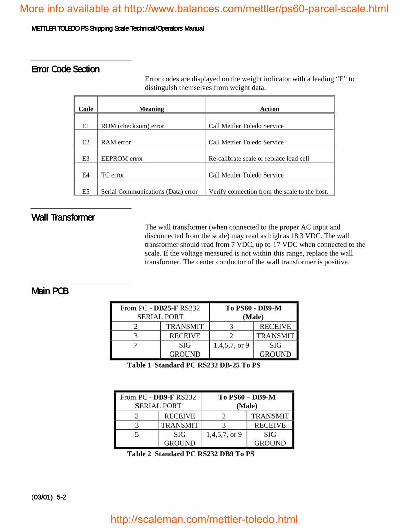
Error Code SectionError Code SectionError Code SectionError Code SectionError codes are displayed on the weight indicator with a leading “E” todistinguish themselves from weight data.
Code Meaning Action
E1 ROM (checksum) error Call Mettler Toledo Service
E2 RAM error Call Mettler Toledo Service
E3 EEPROM error Re-calibrate scale or replace load cell
E4 TC error Call Mettler Toledo Service
E5 Serial Communications (Data) error Verify connection from the scale to the host.
Wall TransformerWall TransformerWall TransformerWall TransformerThe wall transformer (when connected to the proper AC input anddisconnected from the scale) may read as high as 18.3 VDC. The walltransformer should read from 7 VDC, up to 17 VDC when connected to thescale. If the voltage measured is not within this range, replace the walltransformer. The center conductor of the wall transformer is positive.
Main PCBMain PCBMain PCBMain PCB
From PC - DB25-F RS232SERIAL PORT
To PS60 - DB9-M(Male)
2 TRANSMIT 3 RECEIVE3 RECEIVE 2 TRANSMIT7 SIG
GROUND1,4,5,7, or 9 SIG
GROUND
Table 1 Standard PC RS232 DB-25 To PS
From PC - DB9-F RS232SERIAL PORT
To PS60 – DB9-M(Male)
2 RECEIVE 2 TRANSMIT3 TRANSMIT 3 RECEIVE5 SIG
GROUND1,4,5,7, or 9 SIG
GROUND
Table 2 Standard PC RS232 DB9 To PS
More info available at http://www.balances.com/mettler/ps60-parcel-scale.html
http://scaleman.com/mettler-toledo.html
Chapter 5: Chapter 5: Chapter 5: Chapter 5: Service and MaintenanceService and MaintenanceService and MaintenanceService and Maintenance Load Cell ReplacementLoad Cell ReplacementLoad Cell ReplacementLoad Cell Replacement
(03/01) (03/01) (03/01) (03/01) 5-35-35-35-3
To test the Main PCB: (Unit must be setup for standard MT communications(Default)):
1.1.1.1. Start your communications software such as ComTool (Part NumberKN000000K64).
2.2.2.2. Setup your software for:
• 7 data bits• Even parity• 1 stop bit• Baud rate that matches the computer’s baud rate
Blank or Half DisplayBlank or Half DisplayBlank or Half DisplayBlank or Half DisplayRemove power then check the display interface harness from the scale to thedisplay. Apply power the unit. If the blank display continues, replace the0270 Display.
No Keypad InteractionNo Keypad InteractionNo Keypad InteractionNo Keypad InteractionTo test operation of the keypad, remove power, then reapply. With power tothe unit, attempt to enter setup mode by pressing and holding the UNITS key.If the display does not indicate setup mode, replace the 0270 Diplay.
Indicator LockedIndicator LockedIndicator LockedIndicator LockedTo test operation of the indicator, remove power, then reapply. With power tothe unit, add weight. If no motion is displayed, replace either the load cell orthe Logic PCB.
Load CellLoad CellLoad CellLoad CellReplacementReplacementReplacementReplacement
For load cell replacement, please use current revision of 15302300A for PS60(3000d) and PS6L, use 15828000A for PS60 multi-interval versions(2x3000d), and 15834400A for PS2+ models.
Installing the Battery KitInstalling the Battery KitInstalling the Battery KitInstalling the Battery KitThe following instructions describe battery installation (alkaline cell) for thePS shipping scale (PS60 model only). Under normal operation, battery life isapproximately 40 hours. Sleep mode reduces power consumption by 60% and
More info available at http://www.balances.com/mettler/ps60-parcel-scale.html
http://scaleman.com/mettler-toledo.html
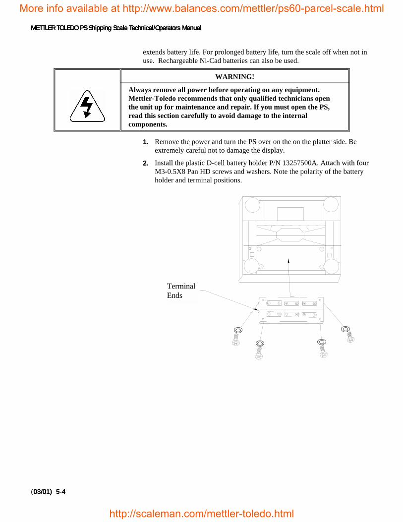
METTLER TOLEDO PS Shipping Scale Technical/Operators ManualMETTLER TOLEDO PS Shipping Scale Technical/Operators ManualMETTLER TOLEDO PS Shipping Scale Technical/Operators ManualMETTLER TOLEDO PS Shipping Scale Technical/Operators Manual
(03/01) 03/01) 03/01) 03/01) 5-45-45-45-4
extends battery life. For prolonged battery life, turn the scale off when not inuse. Rechargeable Ni-Cad batteries can also be used.
WARNING!
Always remove all power before operating on any equipment.Mettler-Toledo recommends that only qualified technicians openthe unit up for maintenance and repair. If you must open the PS,read this section carefully to avoid damage to the internalcomponents.
1.1.1.1. Remove the power and turn the PS over on the on the platter side. Beextremely careful not to damage the display.
2.2.2.2. Install the plastic D-cell battery holder P/N 13257500A. Attach with fourM3-0.5X8 Pan HD screws and washers. Note the polarity of the batteryholder and terminal positions.
TerminalEnds
More info available at http://www.balances.com/mettler/ps60-parcel-scale.html
http://scaleman.com/mettler-toledo.html
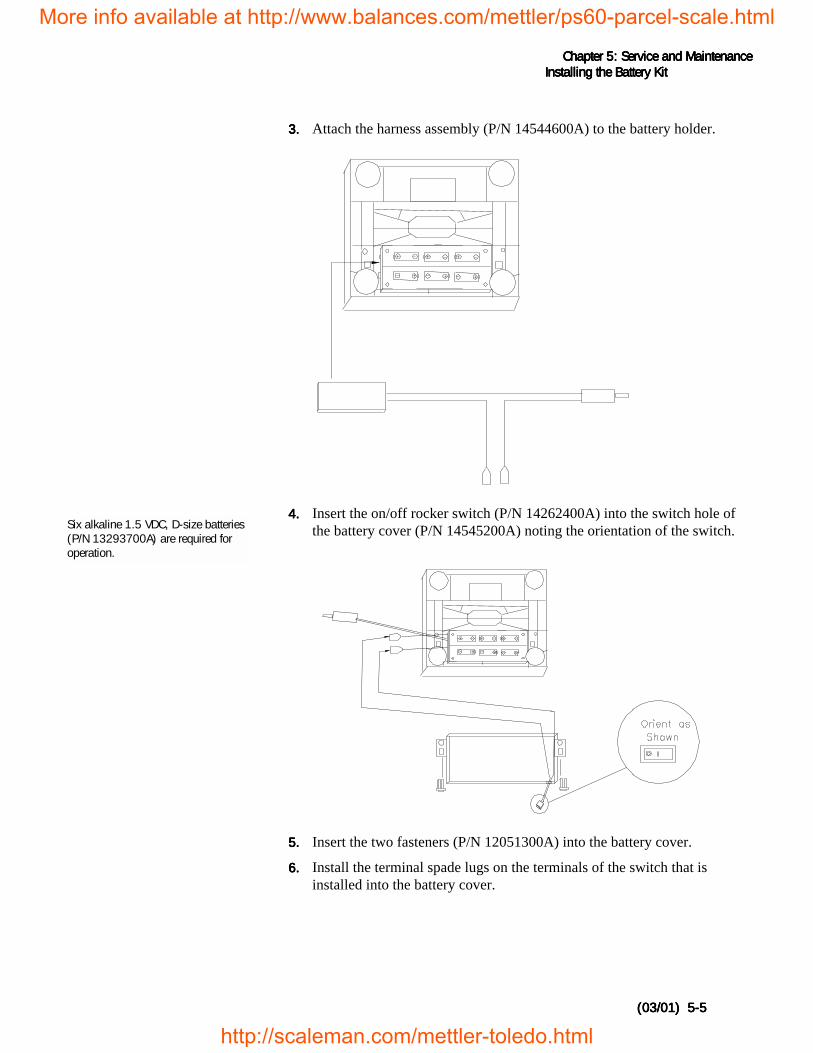
Chapter 5: Chapter 5: Chapter 5: Chapter 5: Service and MaintenanceService and MaintenanceService and MaintenanceService and Maintenance Installing the Battery KitInstalling the Battery KitInstalling the Battery KitInstalling the Battery Kit
(03/01) (03/01) (03/01) (03/01) 5-55-55-55-5
3.3.3.3. Attach the harness assembly (P/N 14544600A) to the battery holder.
4.4.4.4. Insert the on/off rocker switch (P/N 14262400A) into the switch hole ofthe battery cover (P/N 14545200A) noting the orientation of the switch.
5.5.5.5. Insert the two fasteners (P/N 12051300A) into the battery cover.
6.6.6.6. Install the terminal spade lugs on the terminals of the switch that isinstalled into the battery cover.
Six alkaline 1.5 VDC, D-size batteries(P/N 13293700A) are required foroperation.
More info available at http://www.balances.com/mettler/ps60-parcel-scale.html
http://scaleman.com/mettler-toledo.html
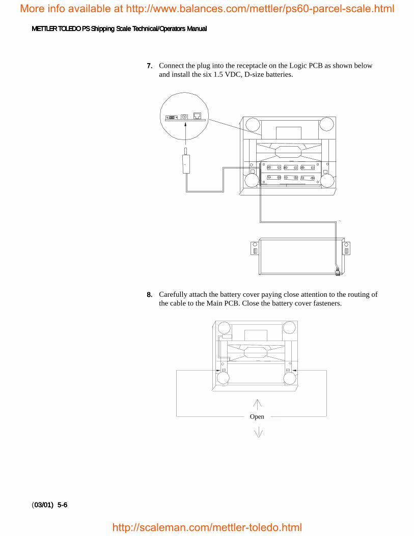
METTLER TOLEDO PS Shipping Scale Technical/Operators ManualMETTLER TOLEDO PS Shipping Scale Technical/Operators ManualMETTLER TOLEDO PS Shipping Scale Technical/Operators ManualMETTLER TOLEDO PS Shipping Scale Technical/Operators Manual
(03/01) 03/01) 03/01) 03/01) 5-65-65-65-6
7.7.7.7. Connect the plug into the receptacle on the Logic PCB as shown belowand install the six 1.5 VDC, D-size batteries.
8.8.8.8. Carefully attach the battery cover paying close attention to the routing ofthe cable to the Main PCB. Close the battery cover fasteners.
Open
More info available at http://www.balances.com/mettler/ps60-parcel-scale.html
http://scaleman.com/mettler-toledo.html
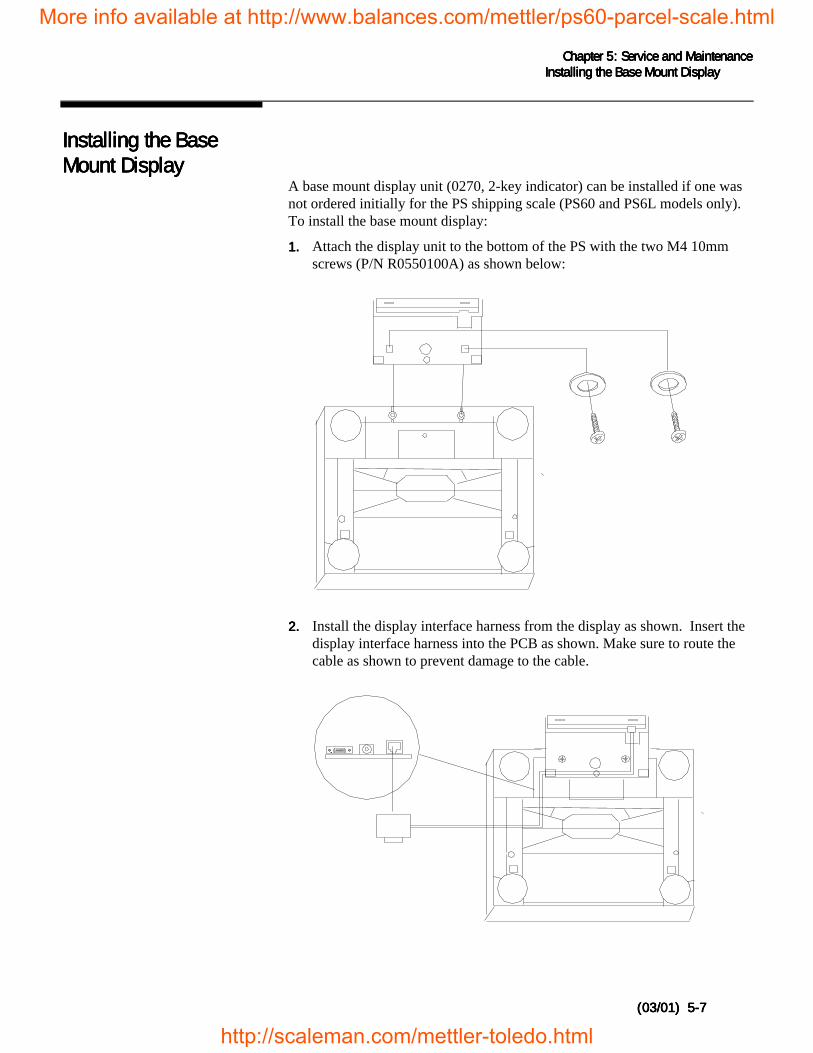
Chapter 5: Chapter 5: Chapter 5: Chapter 5: Service and MaintenanceService and MaintenanceService and MaintenanceService and Maintenance Installing the Base Mount DisplayInstalling the Base Mount DisplayInstalling the Base Mount DisplayInstalling the Base Mount Display
(03/01) (03/01) (03/01) (03/01) 5-75-75-75-7
Installing the BaseInstalling the BaseInstalling the BaseInstalling the BaseMount DisplayMount DisplayMount DisplayMount Display
A base mount display unit (0270, 2-key indicator) can be installed if one wasnot ordered initially for the PS shipping scale (PS60 and PS6L models only).To install the base mount display:
1.1.1.1. Attach the display unit to the bottom of the PS with the two M4 10mmscrews (P/N R0550100A) as shown below:
2.2.2.2. Install the display interface harness from the display as shown. Insert thedisplay interface harness into the PCB as shown. Make sure to route thecable as shown to prevent damage to the cable.
More info available at http://www.balances.com/mettler/ps60-parcel-scale.html
http://scaleman.com/mettler-toledo.html
METTLER TOLEDO PS Shipping Scale Technical/Operators ManualMETTLER TOLEDO PS Shipping Scale Technical/Operators ManualMETTLER TOLEDO PS Shipping Scale Technical/Operators ManualMETTLER TOLEDO PS Shipping Scale Technical/Operators Manual
(03/01) 03/01) 03/01) 03/01) 5-85-85-85-8
Installing the Ball TopInstalling the Ball TopInstalling the Ball TopInstalling the Ball TopTransfer PlatterTransfer PlatterTransfer PlatterTransfer Platter
A ball top transfer platter is available for the PS. (Ball top transfer platters arestandard on the PS2+ model.) To install the ball transfer platter:
1.1.1.1. Remove the platter supplied with the PS.
2.2.2.2. Place the ball top transfer platter on the PS.
3.3.3.3. Ensure that the ball top transfer platter drops into place withoutmechanical interference.
Note: If the unit fails to capture zero after power-up, re-calibration willbe required.
More info available at http://www.balances.com/mettler/ps60-parcel-scale.html
http://scaleman.com/mettler-toledo.html

Chapter 6: Chapter 6: Chapter 6: Chapter 6: Parts and AccessoriesParts and AccessoriesParts and AccessoriesParts and AccessoriesPS60/PS6LPS60/PS6LPS60/PS6LPS60/PS6L
(03/01) (03/01) (03/01) (03/01) 6-16-16-16-1
6666 Parts and AccessoriesParts and AccessoriesParts and AccessoriesParts and AccessoriesPlease refer to the following diagrams and parts lists when ordering parts andaccessories for the PS shipping scale.
More info available at http://www.balances.com/mettler/ps60-parcel-scale.html
http://scaleman.com/mettler-toledo.html
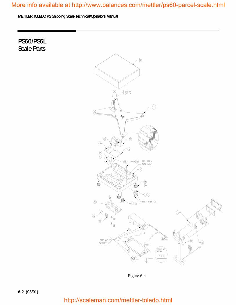
METTLER TOLEDO PS Shipping Scale Technical/Operators ManualMETTLER TOLEDO PS Shipping Scale Technical/Operators ManualMETTLER TOLEDO PS Shipping Scale Technical/Operators ManualMETTLER TOLEDO PS Shipping Scale Technical/Operators Manual
6-26-26-26-2 (03/01) (03/01) (03/01) (03/01)
PS60/PS6LPS60/PS6LPS60/PS6LPS60/PS6LScale PartsScale PartsScale PartsScale Parts
More info available at http://www.balances.com/mettler/ps60-parcel-scale.html
http://scaleman.com/m
Figure 6-a
ettler-toledo.html
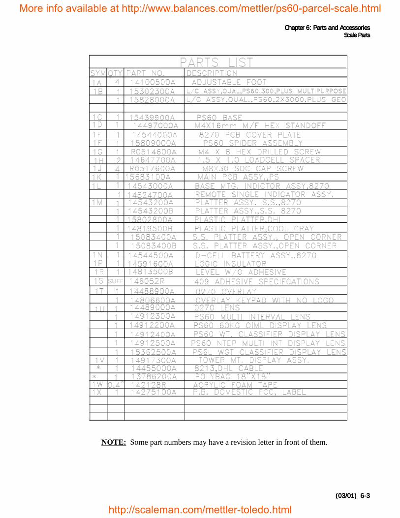
Chapter 6: Chapter 6: Chapter 6: Chapter 6: Parts and AccessoriesParts and AccessoriesParts and AccessoriesParts and AccessoriesScale PartsScale PartsScale PartsScale Parts
(03/01) (03/01) (03/01) (03/01) 6-36-36-36-3
NOTE: Some part numbers may have a revision letter in front of them.
More info available at http://www.balances.com/mettler/ps60-parcel-scale.html
http://scaleman.com/mettler-toledo.html
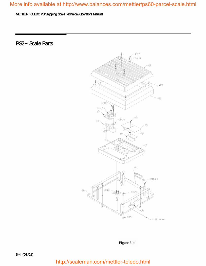
METTLER TOLEDO PS Shipping Scale Technical/Operators ManualMETTLER TOLEDO PS Shipping Scale Technical/Operators ManualMETTLER TOLEDO PS Shipping Scale Technical/Operators ManualMETTLER TOLEDO PS Shipping Scale Technical/Operators Manual
6-46-46-46-4 (03/01) (03/01) (03/01) (03/01)
PS2+ Scale PartsPS2+ Scale PartsPS2+ Scale PartsPS2+ Scale Parts
Figure 6-b
More info available at http://www.balances.com/mettler/ps60-parcel-scale.html
http://scaleman.com/mettler-toledo.html
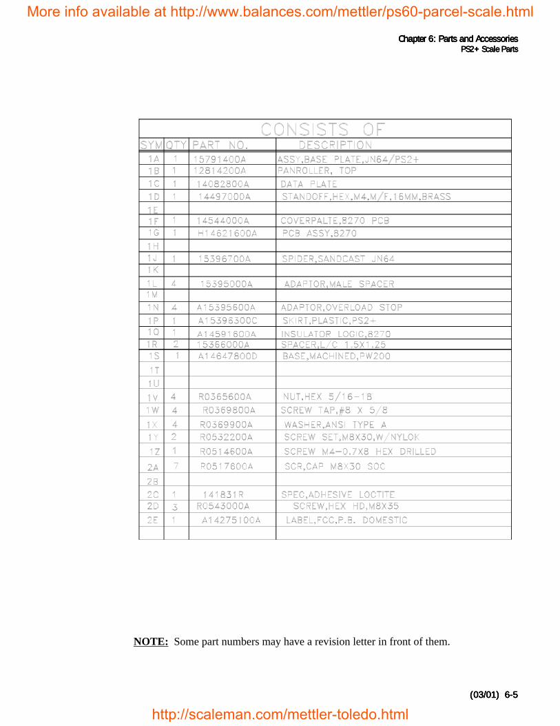
Chapter 6: Chapter 6: Chapter 6: Chapter 6: Parts and AccessoriesParts and AccessoriesParts and AccessoriesParts and AccessoriesPS2+ Scale PartsPS2+ Scale PartsPS2+ Scale PartsPS2+ Scale Parts
(03/01) (03/01) (03/01) (03/01) 6-56-56-56-5
NOTE: Some part numbers may have a revision letter in front of them.
More info available at http://www.balances.com/mettler/ps60-parcel-scale.html
http://scaleman.com/mettler-toledo.html
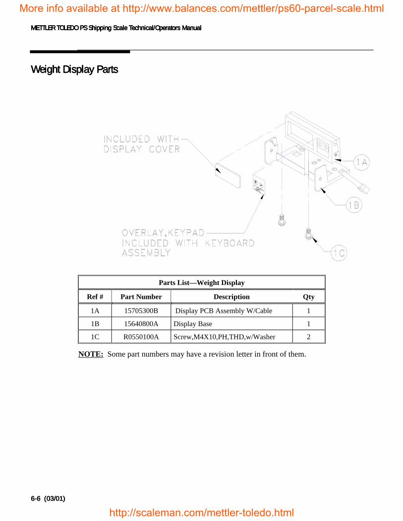
METTLER TOLEDO PS Shipping Scale Technical/Operators ManualMETTLER TOLEDO PS Shipping Scale Technical/Operators ManualMETTLER TOLEDO PS Shipping Scale Technical/Operators ManualMETTLER TOLEDO PS Shipping Scale Technical/Operators Manual
6-66-66-66-6 (03/01) (03/01) (03/01) (03/01)
Weight Display PartsWeight Display PartsWeight Display PartsWeight Display Parts
Parts List—Weight Display
Ref # Part Number Description Qty
1A 15705300B Display PCB Assembly W/Cable 1
1B 15640800A Display Base 1
1C R0550100A Screw,M4X10,PH,THD,w/Washer 2
NOTE: Some part numbers may have a revision letter in front of them.
More info available at http://www.balances.com/mettler/ps60-parcel-scale.html
http://scaleman.com/mettler-toledo.html
Appendix: Host InterfaceAppendix: Host InterfaceAppendix: Host InterfaceAppendix: Host InterfaceCommunication ParametersCommunication ParametersCommunication ParametersCommunication Parameters
(03/01) Appendix-(03/01) Appendix-(03/01) Appendix-(03/01) Appendix-1111
Appendix: Host InterfaceAppendix: Host InterfaceAppendix: Host InterfaceAppendix: Host Interface
The METTLER TOLEDO PS shipping scale can function as a peripheraldevice to a host computer. In host mode you can:
• Calibrate the scale
• Configure setup parameters
• Request and receive weight data when the scale is in a stable state
• Request and receive the scale’s status when the scale is in an unstable orinvalid state
• Zero the scale and/or switch units (depending on setup)
This section presents information and instructions on how to use the PS inhost mode.
CommunicationCommunicationCommunicationCommunicationParametersParametersParametersParameters
Data is transmitted and received by the scale through an RS-232 serial portconnection. The following communication parameters are supported:
• Baud Rate (300, 1200, 2400, 4800, 9600, 19200)• Parity (no, even, odd, mark, space)• ASCII bit string (7 or 8)• Stop bits (1, 2)• The scale only responds to commands, continuous data output is not
available.
ProtocolsProtocolsProtocolsProtocolsThe scale can be programmed to respond to a selected “menu” of definedprotocols. The host sends requests to the scale in the form of ASCII data andcontrol characters as determined by the selected protocol. The scale respondsto the host with a string of ASCII characters. ASCII characters and theirbinary conversions are listed in the following table:
The scale does not reply to hostweight commands if it is in setupmode or if the scale cannot capturezero on power-up.
More info available at http://www.balances.com/mettler/ps60-parcel-scale.html
http://scaleman.com/mettler-toledo.html
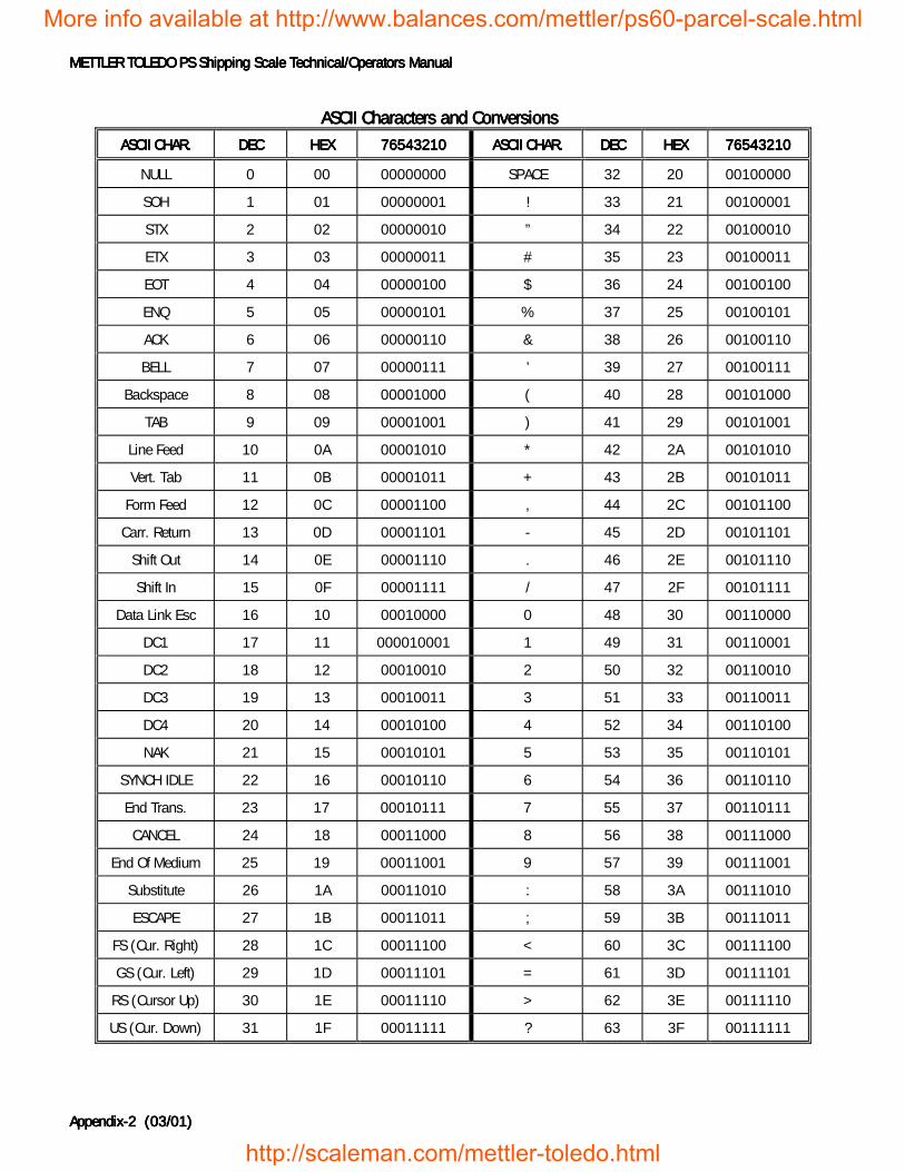
METTLER TOLEDO PS Shipping Scale Technical/Operators ManualMETTLER TOLEDO PS Shipping Scale Technical/Operators ManualMETTLER TOLEDO PS Shipping Scale Technical/Operators ManualMETTLER TOLEDO PS Shipping Scale Technical/Operators Manual
Appendix-Appendix-Appendix-Appendix-2222 (03/01) (03/01) (03/01) (03/01)
ASCII Characters and ConversionsASCII Characters and ConversionsASCII Characters and ConversionsASCII Characters and ConversionsASCII CHAR.ASCII CHAR.ASCII CHAR.ASCII CHAR. DECDECDECDEC HEXHEXHEXHEX 76543210765432107654321076543210 ASCII CHAR.ASCII CHAR.ASCII CHAR.ASCII CHAR. DECDECDECDEC HEXHEXHEXHEX 76543210765432107654321076543210
NULL 0 00 00000000 SPACE 32 20 00100000
SOH 1 01 00000001 ! 33 21 00100001
STX 2 02 00000010 ” 34 22 00100010
ETX 3 03 00000011 # 35 23 00100011
EOT 4 04 00000100 $ 36 24 00100100
ENQ 5 05 00000101 % 37 25 00100101
ACK 6 06 00000110 & 38 26 00100110
BELL 7 07 00000111 ’ 39 27 00100111
Backspace 8 08 00001000 ( 40 28 00101000
TAB 9 09 00001001 ) 41 29 00101001
Line Feed 10 0A 00001010 * 42 2A 00101010
Vert. Tab 11 0B 00001011 + 43 2B 00101011
Form Feed 12 0C 00001100 , 44 2C 00101100
Carr. Return 13 0D 00001101 - 45 2D 00101101
Shift Out 14 0E 00001110 . 46 2E 00101110
Shift In 15 0F 00001111 / 47 2F 00101111
Data Link Esc 16 10 00010000 0 48 30 00110000
DC1 17 11 000010001 1 49 31 00110001
DC2 18 12 00010010 2 50 32 00110010
DC3 19 13 00010011 3 51 33 00110011
DC4 20 14 00010100 4 52 34 00110100
NAK 21 15 00010101 5 53 35 00110101
SYNCH IDLE 22 16 00010110 6 54 36 00110110
End Trans. 23 17 00010111 7 55 37 00110111
CANCEL 24 18 00011000 8 56 38 00111000
End Of Medium 25 19 00011001 9 57 39 00111001
Substitute 26 1A 00011010 : 58 3A 00111010
ESCAPE 27 1B 00011011 ; 59 3B 00111011
FS (Cur. Right) 28 1C 00011100 < 60 3C 00111100
GS (Cur. Left) 29 1D 00011101 = 61 3D 00111101
RS (Cursor Up) 30 1E 00011110 > 62 3E 00111110
US (Cur. Down) 31 1F 00011111 ? 63 3F 00111111
More info available at http://www.balances.com/mettler/ps60-parcel-scale.html
http://scaleman.com/mettler-toledo.html
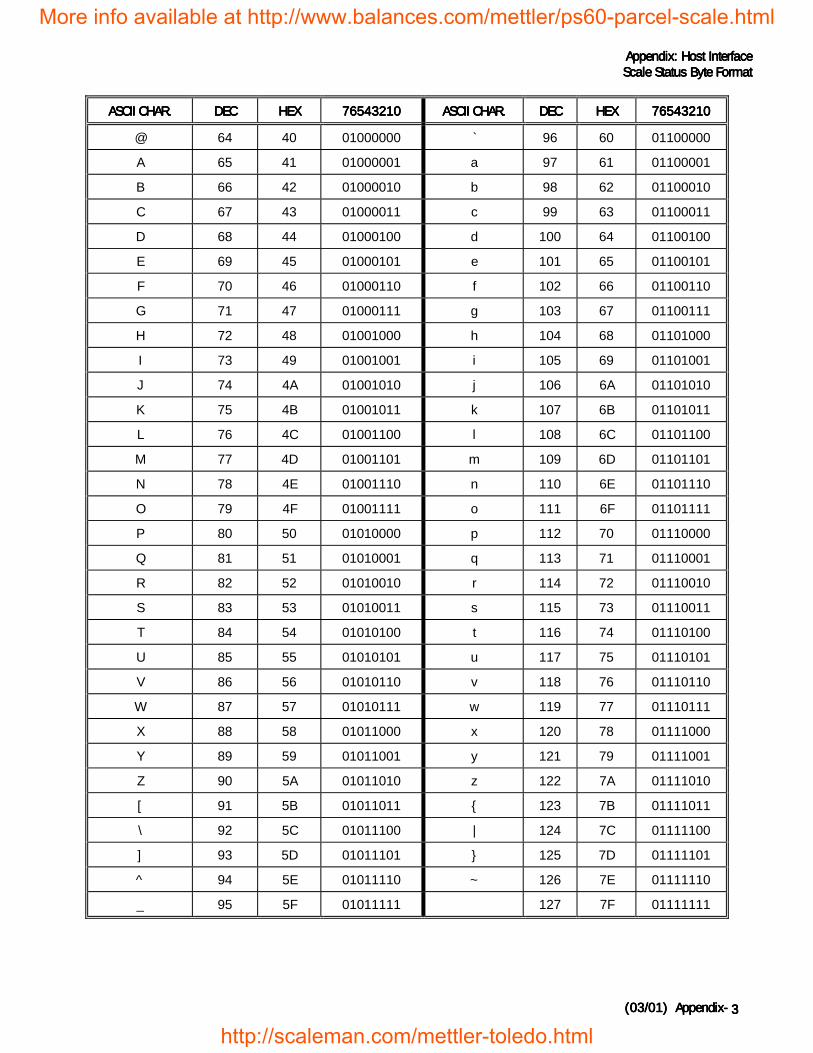
Appendix: Host InterfaceAppendix: Host InterfaceAppendix: Host InterfaceAppendix: Host InterfaceScale Status Byte FormatScale Status Byte FormatScale Status Byte FormatScale Status Byte Format
(03/01) Appendix-(03/01) Appendix-(03/01) Appendix-(03/01) Appendix- 3333
ASCII CHAR.ASCII CHAR.ASCII CHAR.ASCII CHAR. DECDECDECDEC HEXHEXHEXHEX 76543210765432107654321076543210 ASCII CHAR.ASCII CHAR.ASCII CHAR.ASCII CHAR. DECDECDECDEC HEXHEXHEXHEX 76543210765432107654321076543210
@ 64 40 01000000 ` 96 60 01100000
A 65 41 01000001 a 97 61 01100001
B 66 42 01000010 b 98 62 01100010
C 67 43 01000011 c 99 63 01100011
D 68 44 01000100 d 100 64 01100100
E 69 45 01000101 e 101 65 01100101
F 70 46 01000110 f 102 66 01100110
G 71 47 01000111 g 103 67 01100111
H 72 48 01001000 h 104 68 01101000
I 73 49 01001001 i 105 69 01101001
J 74 4A 01001010 j 106 6A 01101010
K 75 4B 01001011 k 107 6B 01101011
L 76 4C 01001100 l 108 6C 01101100
M 77 4D 01001101 m 109 6D 01101101
N 78 4E 01001110 n 110 6E 01101110
O 79 4F 01001111 o 111 6F 01101111
P 80 50 01010000 p 112 70 01110000
Q 81 51 01010001 q 113 71 01110001
R 82 52 01010010 r 114 72 01110010
S 83 53 01010011 s 115 73 01110011
T 84 54 01010100 t 116 74 01110100
U 85 55 01010101 u 117 75 01110101
V 86 56 01010110 v 118 76 01110110
W 87 57 01010111 w 119 77 01110111
X 88 58 01011000 x 120 78 01111000
Y 89 59 01011001 y 121 79 01111001
Z 90 5A 01011010 z 122 7A 01111010
[ 91 5B 01011011 { 123 7B 01111011
\ 92 5C 01011100 | 124 7C 01111100
] 93 5D 01011101 } 125 7D 01111101
^ 94 5E 01011110 ~ 126 7E 01111110
_ 95 5F 01011111 127 7F 01111111
More info available at http://www.balances.com/mettler/ps60-parcel-scale.html
http://scaleman.com/mettler-toledo.html
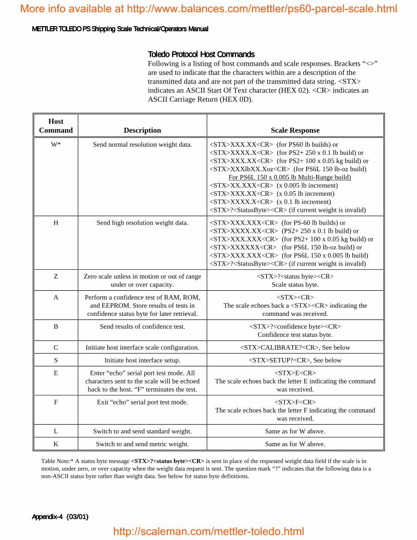
METTLER TOLEDO PS Shipping Scale Technical/Operators ManualMETTLER TOLEDO PS Shipping Scale Technical/Operators ManualMETTLER TOLEDO PS Shipping Scale Technical/Operators ManualMETTLER TOLEDO PS Shipping Scale Technical/Operators Manual
Appendix-Appendix-Appendix-Appendix-4444 (03/01) (03/01) (03/01) (03/01)
Toledo Protocol Host CommandsToledo Protocol Host CommandsToledo Protocol Host CommandsToledo Protocol Host CommandsFollowing is a listing of host commands and scale responses. Brackets “<>”are used to indicate that the characters within are a description of thetransmitted data and are not part of the transmitted data string. <STX>indicates an ASCII Start Of Text character (HEX 02). <CR> indicates anASCII Carriage Return (HEX 0D).
HostCommand Description Scale Response
W* Send normal resolution weight data. <STX>XXX.XX<CR> (for PS60 lb builds) or<STX>XXXX.X<CR> (for PS2+ 250 x 0.1 lb build) or<STX>XXX.XX<CR> (for PS2+ 100 x 0.05 kg build) or<STX>XXXlbXX.Xoz<CR> (for PS6L 150 lb-oz build) For PS6L 150 x 0.005 lb Multi-Range build)<STX>XX.XXX<CR> (x 0.005 lb increment)<STX>XXX.XX<CR> (x 0.05 lb increment)<STX>XXXX.X<CR> (x 0.1 lb increment)<STX>?<StatusByte><CR> (if current weight is invalid)
H Send high resolution weight data. <STX>XXX.XXX<CR> (for PS-60 lb builds) or<STX>XXXX.XX<CR> (PS2+ 250 x 0.1 lb build) or<STX>XXX.XXX<CR> (for PS2+ 100 x 0.05 kg build) or<STX>XXXXXX<CR> (for PS6L 150 lb-oz build) or<STX>XXX.XXX<CR> (for PS6L 150 x 0.005 lb build)<STX>?<StatusByte><CR> (if current weight is invalid)
Z Zero scale unless in motion or out of rangeunder or over capacity.
<STX>?<status byte><CR>Scale status byte.
A Perform a confidence test of RAM, ROM,and EEPROM. Store results of tests in
confidence status byte for later retrieval.
<STX><CR>The scale echoes back a <STX><CR> indicating the
command was received.
B Send results of confidence test. <STX>?<confidence byte><CR>Confidence test status byte.
C Initiate host interface scale configuration. <STX>CALIBRATE?<CR>, See below
S Initiate host interface setup. <STX>SETUP?<CR>, See below
E Enter “echo” serial port test mode. Allcharacters sent to the scale will be echoedback to the host. “F” terminates the test.
<STX>E<CR>The scale echoes back the letter E indicating the command
was received.
F Exit “echo” serial port test mode. <STX>F<CR>The scale echoes back the letter F indicating the command
was received.
L Switch to and send standard weight. Same as for W above.
K Switch to and send metric weight. Same as for W above.
Table Note:* A status byte message <STX>?<status byte><CR> is sent in place of the requested weight data field if the scale is inmotion, under zero, or over capacity when the weight data request is sent. The question mark “?” indicates that the following data is anon-ASCII status byte rather than weight data. See below for status byte definitions.
More info available at http://www.balances.com/mettler/ps60-parcel-scale.html
http://scaleman.com/mettler-toledo.html
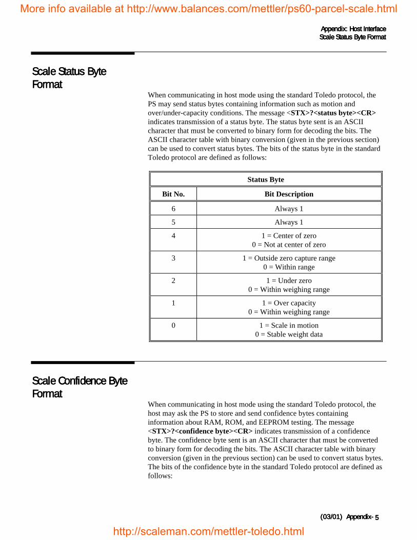
Appendix: Host InterfaceAppendix: Host InterfaceAppendix: Host InterfaceAppendix: Host InterfaceScale Status Byte FormatScale Status Byte FormatScale Status Byte FormatScale Status Byte Format
(03/01) Appendix-(03/01) Appendix-(03/01) Appendix-(03/01) Appendix- 5555
Scale Status ByteScale Status ByteScale Status ByteScale Status ByteFormatFormatFormatFormat
When communicating in host mode using the standard Toledo protocol, thePS may send status bytes containing information such as motion andover/under-capacity conditions. The message <STX>?<status byte><CR>indicates transmission of a status byte. The status byte sent is an ASCIIcharacter that must be converted to binary form for decoding the bits. TheASCII character table with binary conversion (given in the previous section)can be used to convert status bytes. The bits of the status byte in the standardToledo protocol are defined as follows:
Status Byte
Bit No. Bit Description
6 Always 1
5 Always 1
4 1 = Center of zero0 = Not at center of zero
3 1 = Outside zero capture range0 = Within range
2 1 = Under zero0 = Within weighing range
1 1 = Over capacity0 = Within weighing range
0 1 = Scale in motion0 = Stable weight data
Scale Confidence ByteScale Confidence ByteScale Confidence ByteScale Confidence ByteFormatFormatFormatFormat
When communicating in host mode using the standard Toledo protocol, thehost may ask the PS to store and send confidence bytes containinginformation about RAM, ROM, and EEPROM testing. The message<STX>?<confidence byte><CR> indicates transmission of a confidencebyte. The confidence byte sent is an ASCII character that must be convertedto binary form for decoding the bits. The ASCII character table with binaryconversion (given in the previous section) can be used to convert status bytes.The bits of the confidence byte in the standard Toledo protocol are defined asfollows:
More info available at http://www.balances.com/mettler/ps60-parcel-scale.html
http://scaleman.com/mettler-toledo.html
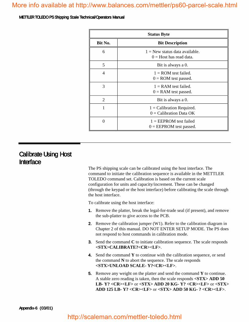
METTLER TOLEDO PS Shipping Scale Technical/Operators ManualMETTLER TOLEDO PS Shipping Scale Technical/Operators ManualMETTLER TOLEDO PS Shipping Scale Technical/Operators ManualMETTLER TOLEDO PS Shipping Scale Technical/Operators Manual
Appendix-Appendix-Appendix-Appendix-6666 (03/01) (03/01) (03/01) (03/01)
Status Byte
Bit No. Bit Description
6 1 = New status data available.0 = Host has read data.
5 Bit is always a 0.
4 1 = ROM test failed.0 = ROM test passed.
3 1 = RAM test failed.0 = RAM test passed.
2 Bit is always a 0.
1 1 = Calibration Required.0 = Calibration Data OK
0 1 = EEPROM test failed0 = EEPROM test passed.
Calibrate Using HostCalibrate Using HostCalibrate Using HostCalibrate Using HostInterfaceInterfaceInterfaceInterface
The PS shipping scale can be calibrated using the host interface. Thecommand to initiate the calibration sequence is available in the METTLERTOLEDO command set. Calibration is based on the current scaleconfiguration for units and capacity/increment. These can be changed(through the keypad or the host interface) before calibrating the scale throughthe host interface.
To calibrate using the host interface:
1.1.1.1. Remove the platter, break the legal-for-trade seal (if present), and removethe sub-platter to give access to the PCB.
2.2.2.2. Remove the calibration jumper (W1). Refer to the calibration diagram inChapter 2 of this manual. DO NOT ENTER SETUP MODE. The PS doesnot respond to host commands in calibration mode.
3.3.3.3. Send the command C to initiate calibration sequence. The scale responds<STX>CALIBRATE?<CR><LF>.
4.4.4.4. Send the command Y to continue with the calibration sequence, or sendthe command N to abort the sequence. The scale responds<STX>UNLOAD SCALE- Y?<CR><LF>.
5.5.5.5. Remove any weight on the platter and send the command Y to continue.A stable zero reading is taken, then the scale responds <STX> ADD 50LB- Y? <CR><LF> or <STX> ADD 20 KG- Y? <CR><LF> or <STX>ADD 125 LB- Y? <CR><LF> or <STX> ADD 50 KG- ? <CR><LF>.
More info available at http://www.balances.com/mettler/ps60-parcel-scale.html
http://scaleman.com/mettler-toledo.html
Appendix: Host InterfaceAppendix: Host InterfaceAppendix: Host InterfaceAppendix: Host InterfaceScale Status Byte FormatScale Status Byte FormatScale Status Byte FormatScale Status Byte Format
(03/01) Appendix-(03/01) Appendix-(03/01) Appendix-(03/01) Appendix- 7777
6.6.6.6. Add the requested calibration weight to the scale, then send the commandY to continue. The scale responds <STX> CAL DONE <CR><LF> or<STX> INCORRECT AMOUNT OF WEIGHT <CR><LF>.
Configure ScaleConfigure ScaleConfigure ScaleConfigure ScaleParameters Using HostParameters Using HostParameters Using HostParameters Using HostInterfaceInterfaceInterfaceInterface
Configuration parameters can also be sent using the host interface. Acommand to send a new scale configuration over the host interface isavailable in the METTLER TOLEDO command set.
To configure using the host interface:
1.1.1.1. From the host computer, send the host command S to initiate theconfiguration setup sequence. The scale responds with the current setbytes:
<STX>X1X2X3X4X5X6X7X8X9X10X11X12X13X14X15X16X17X18X19X20<CR>
2.2.2.2. Determine the command string representing the configuration parametersthat are desired. The command string consists of 22 characters beginningwith an ASCII <STX> and terminated with an ASCII <CR>. Thecommand string represents a 10-byte bit-mapped setup array stored inEEPROM. The 10-byte array is expanded for serial transmission so thatthe high-order four bits of each byte are zeroes and the low-order four bitsare numbers representing the desired option for each program block. Seethe table below for definitions of each byte.
More info available at http://www.balances.com/mettler/ps60-parcel-scale.html
http://scaleman.com/mettler-toledo.html
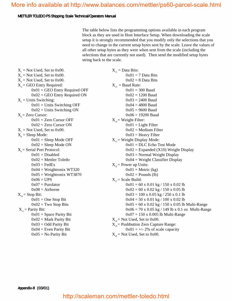
METTLER TOLEDO PS Shipping Scale Technical/Operators ManualMETTLER TOLEDO PS Shipping Scale Technical/Operators ManualMETTLER TOLEDO PS Shipping Scale Technical/Operators ManualMETTLER TOLEDO PS Shipping Scale Technical/Operators Manual
Appendix-Appendix-Appendix-Appendix-8888 (03/01) (03/01) (03/01) (03/01)
The table below lists the programming options available in each programblock as they are used in Host Interface Setup. When downloading the scalesetup it is strongly recommended that you modify only the selections that youneed to change in the current setup bytes sent by the scale. Leave the values ofall other setup bytes as they were when sent from the scale (including theselections that are currently not used). Then send the modified setup bytesstring back to the scale.
X1 = Not Used, Set to 0x00.X2 = Not Used, Set to 0x00.X3 = Not Used, Set to 0x00.X4 = GEO Entry Required:
0x01 = GEO Entry Required OFF0x02 = GEO Entry Required ON
X5 = Units Switching:0x01 = Units Switching OFF0x02 = Units Switching ON
X6 = Zero Cursor:0x01 = Zero Cursor OFF0x02 = Zero Cursor ON
X7 = Not Used, Set to 0x00.X8 = Sleep Mode:
0x01 = Sleep Mode OFF0x02 = Sleep Mode ON
X9 = Serial Port Protocol:0x01 = Disabled0x02 = Mettler Toledo0x03 = FedEx0x04 = Weightronix WT3200x05 = Weightronix WT38700x06 = UPS0x07 = Purolator0x08 = Airborne
X10 = Stop Bit: 0x01 = One Stop Bit
0x02 = Two Stop Bits X11 = Parity Bit:
0x01 = Space Parity Bit0x02 = Mark Parity Bit0x03 = Odd Parity Bit0x04 = Even Parity Bit
0x05 = No Parity Bit
X12 = Data Bits:0x01 = 7 Data Bits0x02 = 8 Data Bits
X13 = Baud Rate:0x01 = 300 Baud0x02 = 1200 Baud0x03 = 2400 Baud0x04 = 4800 Baud0x05 = 9600 Baud0x06 = 19200 Baud
X14 = Weight Filter:0x01 = Light Filter0x02 = Medium Filter0x03 = Heavy Filter
X15 = Weight Display Mode:0x01 = DLC Echo Test Mode0x02 = Expanded (X10) Weight Display0x03 = Normal Weight Display0x04 = Weight Classifier Display
X16 = Power up Units:0x01 = Metric (kg)0x02 = Pounds (lb)
X17 = Scale Build:0x01 = 60 x 0.01 kg / 150 x 0.02 lb0x02 = 60 x 0.02 kg / 150 x 0.05 lb0x03 = 100 x 0.05 kg / 250 x 0.1 lb0x04 = 50 x 0.01 kg / 100 x 0.02 lb0x05 = 60 x 0.02 kg / 150 x 0.05 lb Multi-Range0x06 = 70 x 0.05 kg / 149 lb x 0.1 oz Multi-Range0x07 = 150 x 0.005 lb Multi-Range
X18 = Not Used, Set to 0x00.X19 = Pushbutton Zero Capture Range: 0x01 = +/- 2% of scale capacityX20 = Not Used, Set to 0x00.
More info available at http://www.balances.com/mettler/ps60-parcel-scale.html
http://scaleman.com/mettler-toledo.html

Appendix: Host InterfaceAppendix: Host InterfaceAppendix: Host InterfaceAppendix: Host InterfaceScale Status Byte FormatScale Status Byte FormatScale Status Byte FormatScale Status Byte Format
(03/01) Appendix-(03/01) Appendix-(03/01) Appendix-(03/01) Appendix- 9999
3.3.3.3. Send the command desired new set of bytes to the scale:<STX>Y1Y2 ... Y19Y20<CR>
4.4.4.4. The scale will check to make sure the requested bytes are valid, then willecho the request: <STX>Y1Y2 ... Y19Y20<CR>. Or, if there wereproblems with the request, the scale returns the original, unmodifiedsetup bytes to let the host know there was a problem:
<STX>X1X2 ... X19X20<CR>
5.5.5.5. Send the command Y to continue and store the new setup bytes and thescale will respond with <STX>DONE<CR> when configuration iscomplete or <STX>ABORT<CR> if the modified bytes had problems.
NOTE: At any time the Host can send an N command to abort the SetupDownload mode
Before sending the DONEDONEDONEDONE reply, theconfiguration file is analyzed just as ifit had been constructed using thekeyboard.
You can obtain the currentconfiguration by sending the Scommand. Then you can abortwithout changing by sending the Acommand to abort.
More info available at http://www.balances.com/mettler/ps60-parcel-scale.html
http://scaleman.com/mettler-toledo.html