Embed Size (px)
Citation preview

Prufung Regelungstechnik I (Control Systems I)
Prof. Dr. Lino Guzzella
5. 2. 2011
Ubersetzungshilfe / Translation aid (English)
To be returned at the end of the exam!
Do not mark up this translation aid - The German exam is the only valid version!
All answers must be written on the regular exam sheets (which are in German).
1

Question 1 (Modeling and Linearization) 8 Points
An object of mass m is attached to a spring as shown in the figure below. From the bottom anairflow is blown onto the object. The object’s position is denoted by x(t). The guidances on thesides are frictionless. The air flows with the velocity v(t), which can be adjusted. The liftingforce of the airflow object can be modeled as:
Fa =1
2ca · ρ · A · v2
rel = k · v2rel.
This force depends on the air density ρ, on the coefficient of lift ca, on the object’s cross sectionarea A, and on the relative flow velocity vrel. In this exercise k can be assumed to be constant.The spring is linear (spring stiffness ks) and can be assumed to be massless. The rest positionof the spring is at x = 0. The equilibrium position of the object is denoted by we.All parameters are positive, i.e., k, ks,m,we > 0.
a) (3 Points) Give the differential equations which describe the vertical motion of the ob-ject. Use the air velocity v(t) as input and the object’s position w(t) as output of thesystem. Formulate the equations in standard form, i.e. as a system of nonlinear first order
differential equations
z(t) = f(z(t), v(t)), w(t) = h(z(t), v(t)), z(t) ∈ R2, v(t), w(t) ∈ R.
b) (2 Points) Find the air velocity ve, which keeps the object in equilibrium at position we.Remark: we ≤ m · g/ks.
c) (3 Points) Linearize the system equations around this equilibrium point (normalization isomitted). Give the linearized system equations in the standard form (state space repre-sentation with matrices {A, b, c, d}).
1 / 12

Question 2 (Frequency domain, time domain) 8 Points
The open-loop transfer functions (L1 (s) , L2 (s) , L3 (s) , L4 (s)), the open-loop Nyquist diagrams(Diagram A, Diagram B, Diagram C, Diagram D), and the closed-loop step responses (Stepresponse 1, Step response 2, Step response 3, Step response 4) of 4 systems are given. Identifythe corresponding open-loop Nyquist diagram and the corresponding closed loop step responseof every transfer function. Note your solution in the table below.
Grading:Per correct identification: +1 pointPer false identification: −1 pointMinimum amount of points: 0 points
Table for the solution
L1 (s) = L2 (s) = L3 (s) = L4 (s) =Transfer function
1s2+2s+2 · e−s 3
(s2−s+6)4
(s3+2s2+4s)(−2s+2)
(s2+3s+4)
Nyquist diagram
Step response
Nyquist diagram A
−1 −0.5 0 0.5 1
−1
−0.5
0
0.5
1
Re
Im
Nyquist diagram B
−1 −0.5 0 0.5 1
−1
−0.5
0
0.5
1
Re
Im
2 / 12
Nyquist diagram C
−1 −0.5 0 0.5 1
−1
−0.5
0
0.5
1
Re
Im
Nyquist diagram D
−1 −0.5 0 0.5 1
−1
−0.5
0
0.5
1
ReIm
Step response 1
−1 0 1 2 3 4 5 6 7 8 9 10−5
−4
−3
−2
−1
0
1
2
3
4
5
time [s]
ampl
itude
[−]
Step response 2
−1 0 1 2 3 4 5 6 7 8 9 10
0
0.2
0.4
0.6
0.8
1
1.2
time [s]
ampl
itude
[−]
Step response 3
−1 0 1 2 3 4 5 6 7 8 9 10
0
0.2
0.4
0.6
0.8
1
time [s]
ampl
itude
[−]
Step response 4
−1 0 1 2 3 4 5 6 7 8 9 10
−0.4
−0.2
0
0.2
0.4
0.6
0.8
1
1.2
time [s]
ampl
itude
[−]
3 / 12

Question 3 (Controller Design) 7 Points
The following plant is given
P (s) =10
s · (s + 1)
The plant output is corrupted by high-frequency measurement-noise.
a) (3 points) For the given plant a PD-controller has to be designed.
C(s) = kp · (1 + Td · s)
The control system is required to have a cross-over frequency of√
3 rads
and a phase marginof 60◦. Determine the parameters (kp, Td) of the controller.
b) (3 points) The controller has to be extended by a second order low-pass filter. The transferfunction of the filter is given by:
F (s) =kF
(τ · s + 1)2
It is required that the cross-over frequency of the control systems remains√
3 rads
. Thephase margin has to be 45◦. Determine the parameters of the filter (kF , τ). The controllerparameters (kp, Td) must not be changed.
c) (1 point) What is the reason to extend the controller with a low-pass filter, why is itespecially important in this example? (explain 1 - 2 sentences)
4 / 12
Question 4 (Laplace Transformation) 10 Points
The following two sub-tasks can be solved independently.
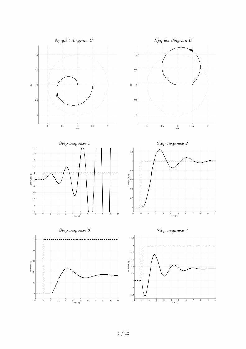
a) (4 Points) The transfer function P (s) is given. Calculate the time-response y(t) of thegiven system. The input signal is u(t), where ω = 2 holds.
P (s) =s + 2
(s + 1) · (s + 3)
u(t) = h(t) · sin(ω · t)
b) (6 Points) The output of a system Σ(s) is measured using a sensor that can be describedby the transfer function Σs(s). The block diagram of the whole system looks as follows1:
The following additional information for the system Σ(s) (for a step response) is available:
• The rise time t90 is 2.5 seconds
• The maximum overshoot ǫ is 25%
i) What is the transfer function of the system Σ(s) (approximately)?
ii) The response of the system on a unit step function was measured. The followingtime-function was fitted to the measured data:
u(t) = h(t)
y(t) = h(t − T ) ·[
1 + a1 · eb1·(t−T ) + eb2·(t−T ) ·(
a2 · cos(ω · (t − T )) + a3 · sin(ω · (t − T )))
]
The corresponding numerical values are as follows:
a1 a2 a3 b1 b2 ω T
-0.1714 -0.8286 -0.86 -2 -0.3059 0.6932 0.01
Determine the time-constant τs and the time-delay T of the sensor.
1Note: The system does not contain any finite zeros.
5 / 12
Question 5 (Stabilizing) 10 Points
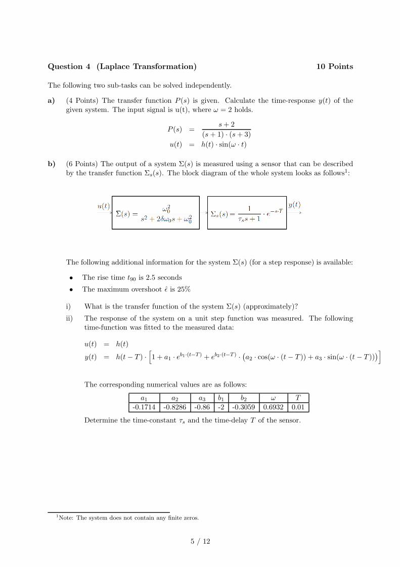
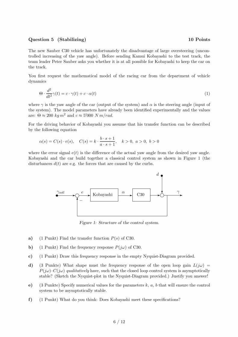
The new Sauber C30 vehicle has unfortunately the disadvantage of large oversteering (uncon-trolled increasing of the yaw angle). Before sending Kamui Kobayashi to the test track, theteam leader Peter Sauber asks you whether it is at all possible for Kobayashi to keep the car onthe track.
You first request the mathematical model of the racing car from the department of vehicledynamics
Θ · d2
dt2γ(t) = c · γ(t) + c · α(t) (1)
where γ is the yaw angle of the car (output of the system) and α is the steering angle (input ofthe system). The model parameters have already been identified experimentally and the valuesare: Θ ≈ 200 kg m2 and c ≈ 5′000 N m/rad.
For the driving behavior of Kobayashi you assume that his transfer function can be describedby the following equation
α(s) = C(s) · e(s), C(s) = k · b · s + 1
a · s + 1, k > 0, a > 0, b > 0
where the error signal e(t) is the difference of the actual yaw angle from the desired yaw angle.Kobayashi and the car build together a classical control system as shown in Figure 1 (thedisturbances d(t) are e.g. the forces that are caused by the curbs.
γsollKobayashi C30
−
γ
d
αe
Figure 1: Structure of the control system.
a) (1 Punkt) Find the transfer function P (s) of C30.
b) (1 Punkt) Find the frequency response P (jω) of C30.
c) (1 Punkt) Draw this frequency response in the empty Nyquist-Diagram provided.
d) (3 Punkte) What shape must the frequency response of the open loop gain L(jω) =P (jω) ·C(jω) qualitatively have, such that the closed loop control system is asymptoticallystable? (Sketch the Nyquist-plot in the Nyquist-Diagram provided.) Justify you answer!
e) (3 Punkte) Specify numerical values for the parameters k, a, b that will ensure the controlsystem to be asymptotically stable.
f) (1 Punkt) What do you think: Does Kobayashi meet these specifications?
6 / 12

Re
Im
−1
−1
+1
+1
Figure 2: Nyquist-Diagram.
7 / 12
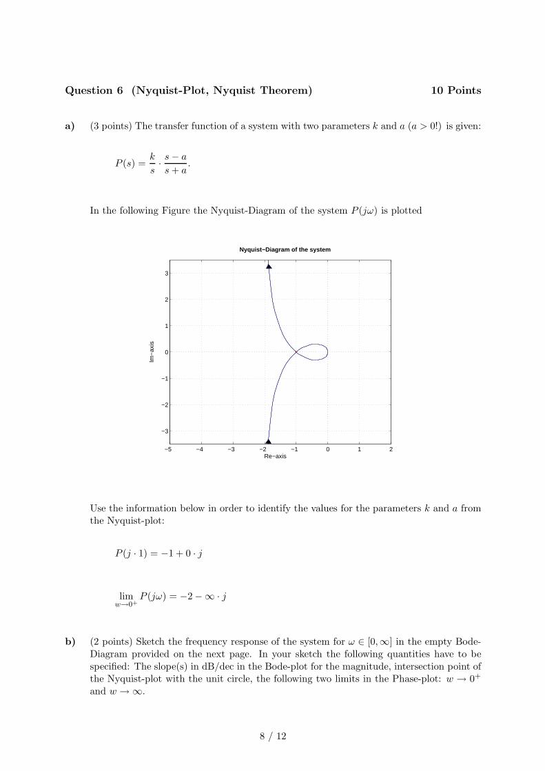
Question 6 (Nyquist-Plot, Nyquist Theorem) 10 Points
a) (3 points) The transfer function of a system with two parameters k and a (a > 0!) is given:
P (s) =k
s· s − a
s + a.
In the following Figure the Nyquist-Diagram of the system P (jω) is plotted
−5 −4 −3 −2 −1 0 1 2
−3
−2
−1
0
1
2
3
Nyquist−Diagram of the system
Re−axis
Im−
axis
Use the information below in order to identify the values for the parameters k and a fromthe Nyquist-plot:
P (j · 1) = −1 + 0 · j
limw→0+
P (jω) = −2 −∞ · j
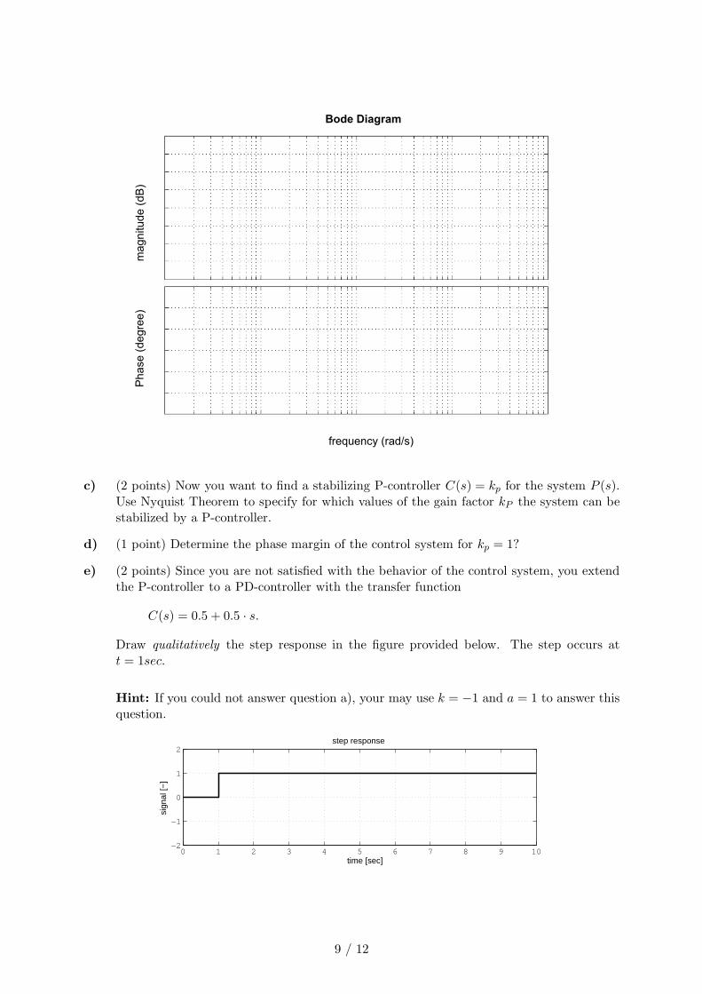
b) (2 points) Sketch the frequency response of the system for ω ∈ [0,∞] in the empty Bode-Diagram provided on the next page. In your sketch the following quantities have to bespecified: The slope(s) in dB/dec in the Bode-plot for the magnitude, intersection point ofthe Nyquist-plot with the unit circle, the following two limits in the Phase-plot: w → 0+
and w → ∞.
8 / 12
Bode Diagram
ma
gn
itu
de
(d
B)
Ph
ase
(d
eg
ree
)
frequency (rad/s)
c) (2 points) Now you want to find a stabilizing P-controller C(s) = kp for the system P (s).Use Nyquist Theorem to specify for which values of the gain factor kP the system can bestabilized by a P-controller.
d) (1 point) Determine the phase margin of the control system for kp = 1?
e) (2 points) Since you are not satisfied with the behavior of the control system, you extendthe P-controller to a PD-controller with the transfer function
C(s) = 0.5 + 0.5 · s.
Draw qualitatively the step response in the figure provided below. The step occurs att = 1sec.
Hint: If you could not answer question a), your may use k = −1 and a = 1 to answer thisquestion.
0 1 2 3 4 5 6 7 8 9 10−2
−1
0
1
2
time [sec]
sign
al [−
]
step response
9 / 12

Question 7 (System Analysis) 8 Points
In biology, the difference in voltage between the interior and exterior of a cell is known as themembrane potential. Its nonlinear dynamics are approximated by the FitzHugh-Nagumo model.Linearized around its equilibrium this is given by
[
x1(t)x2(t)
]
=
[
−0.45 −10.08 −0.05
] [
x1(t)x2(t)
]
+
[
10
]
u(t)
y(t) =[
1 0]
[
x1(t)x2(t)
]
,
where y(t) denotes the difference of the membrane potential to its equilibrium and u(t) anexternal input current, e.g. applied via an electrode.
a) (1 Point) In terms of Lyapunov, is the system stable, asymptotically stable, or unstable?
b) (2 Points)
i) Determine the transfer function of the system. Simplify your result as much aspossible.
ii) Is the system minimum-phase?
c) (1 Point) Is the system completely controllable?
d) (1 Point) Is the system completely observable?
e) (3 Points) Discuss following questions based on the given model and your results from theprevious questions.
i) The membrane potential is slightly deflected from its equilibrium by short-time ap-plication of a small external current. Will it return to its equilibrium?
ii) An external current in form of a step is applied to the system. Will there be a pointin time where the difference of the membrane potential to its equilibrium changessign?
iii) Can the relationship of external current to the difference of membrane potential toits equilibrium be described by a first-order system?
10 / 12

Question 8 (Problem 8) 6 Points
Decide whether the following statements are true or false and check the corresponding check boxwith an X (�×).
You are not required to justify your answers. All questions are equally weighted (1 point).There will be a reduction of one point for a wrong answer 2. Unanswered questions will get 0points. The minimum sum for all questions is 0 points.
a) The differential equation δx = −30 · δx+6 · δu is the linearization of the non-linear systemx = −x3 − 3x + u2 around the equilibrium point {xe = 3, ue = 6}.
� True � False
b) A constant signal u(t) = 1 at the input of a system with the transfer function Σ(s) =s+30
s2−7s+6
produces for t → ∞ a constant output signal of 5.
� True � False
c) The poles of the system with the transfer function Σ(s) = s+1(s+2)(s2+4s+3)
coincide with its
eigenvalues.
� True � False
d) An unstable system with the transfer function 1(s−1)2
can be stabilized by a PD-controller
C(s) = kp + kd · s with the parameters kp and kd.
� True � False
e) A plant with the transfer function P (s) = 1s−5 is stabilized by a P-controller. There is a
disturbance signal w at the input of the plant (see figure below!).
kP1
s 5–-----------
w
–
r y+
+
With a gain factor kP = 5 it can be achieved that the maximum of the impulse response(for zero initial condition and r = 0) will not not become greater that 1 (i.e.y(t) ≤ 1,∀t ≥ 0).
� True � False
2Be aware of this fact!
11 / 12
f) A PI-controller is used to control an asymptotic stable system. For the adjusted controllerparameters kp (gain of the proportional part) and Ti (time constant of the integral part),the output signal of the control system shows a harmonic oscillation (control system iscritically stable). By increasing the time constant of the integral part Ti, the controlsystem will become asymptotically stable .
� True � False
g) An asymptotically stable control system has at least a guaranteed gain margin of k < 2 ifits sensitivity function fulfills the condition max
ω|S(jω)| < 2.
� True � False
h) The open loop gain of a control system L(s) = C(s) · P (s) has two unstable poles. Thecontrol system is asymptotically stable because the Nyquist-plot L(jω) encircles the point−1 twice in the clockwise direction.
� True � False
12 / 12